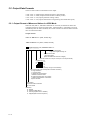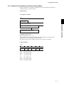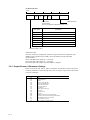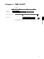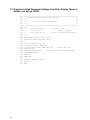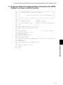
1
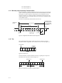
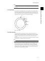
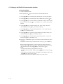
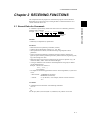
User’s Guide
http://www.omega.com
e-mail: [email protected]
VR200/RS-422A
Communications
Instruction Manual
OMEGAne t ® On-Line Service
http://www
.omega.com
Internet e-mail
[email protected]
Servicing North America:
USA:
ISO 9001 Certified
Canada:
One Omega Drive, Box 4047
Stamford, CT 06907-0047
Tel: (203) 359-1660
e-mail: [email protected]
976 Bergar
Laval (Quebec) H7L 5A1
Tel: (514) 856-6928
e-mail: [email protected]
FAX: (203) 359-7700
FAX: (514) 856-6886
For immediate technical or application assistance:
USA and Canada: Sales Service: 1-800-826-6342 / 1-800-TC-OMEGASM
Customer Service: 1-800-622-2378 / 1-800-622-BESTSM
Engineering Service: 1-800-872-9436 / 1-800-USA-WHENSM
TELEX: 996404 EASYLINK: 62968934 CABLE: OMEGA
Mexico and
Latin America:
Tel: (001) 800-826-6342
En Espan˜ol: (001) 203-359-7803
FAX: (001) 203-359-7807
e-mail: [email protected]
Servicing Europe:
Benelux:
Postbus 8034, 1180 LAAmstelveen, The Netherlands
Tel: (31) 20 6418405
FAX: (31) 20 6434643
Toll Free in Benelux: 0800 0993344
e-mail: [email protected]
Czech Republic:
ul. Rude armady 1868, 733 01 Karvina-Hranice
Tel: 420 (69) 6311899
FAX: 420 (69) 6311114
Toll Free: 0800-1-66342
e-mail: [email protected]
France:
9, rue Denis Papin, 78190 Trappes
Tel: (33) 130-621-400
Toll Free in France: 0800-4-06342
e-mail: [email protected]
FAX: (33) 130-699-120
Germany/Austria: Daimlerstrasse 26, D-75392 Deckenpfronn, Germany
Tel: 49 (07056) 3017
Toll Free in Germany: 0130 11 21 66
e-mail: [email protected]
United Kingdom:
ISO 9002 Certified
FAX: 49 (07056) 8540
One Omega Drive, River Bend Technology Centre
Northbank, Irlam, Manchester
M44 5EX, United Kingdom
Tel: +44 (0) 161 777-6611
FAX: +44 (0) 161 777-6622
Toll Free in United Kingdom: 0800-488-488
e-mail: [email protected]
It is the policy of OMEGA to comply with all worldwide safety and EMC/EMI regulations that
apply. OMEGA is constantly pursuing certification of its products to the European New Approach
Directives. OMEGA will add the CE mark to every appropriate device upon certification.
The information contained in this document is believed to be correct, but OMEGA Engineering, Inc. accepts
no liability for any errors it contains, and reserves the right to alter specifications without notice.
WARNING: These products are not designed for use in, and should not be used for, patient-connected applications.
PREFACE
This instruction manual describes the optional RS-422-A communication function for
the VR200 view recorder. For details concerning the operations of the recorder, refer to
the instruction manual for the VR200.
Trademarks
• “IBM” is a trademark of International Business Machines Corporation.
• “MS-DOS” and “Windows” are trademarks of Microsoft Corporation.
1
CONTENTS
PREFACE
Chapter 1 INSTALLING THE RS-422-A INTERFACE
1.1 Interface Specifications ................................................................................................................ 1-1
1.2 Interface Terminal ........................................................................................................................ 1-2
1.2.1 Terminal Assignment ...................................................................................................... 1-2
1.2.2 Cable Termination .......................................................................................................... 1-2
1.3 Communication Wiring ................................................................................................................ 1-3
1.4 Data Configuration ....................................................................................................................... 1-4
1.4.1 Start-stop (Asynchronous) Communication ................................................................... 1-4
1.4.2 Text ................................................................................................................................. 1-4
1.4.3 Input Buffer ..................................................................................................................... 1-5
1.4.4 Buffer Overflow .............................................................................................................. 1-5
1.5 Setting up the RS-422-A Communication Interface ..................................................................... 1-6
Chapter 2 RECEIVING FUNCTIONS
2.1 General Rules for Commands ....................................................................................................... 2-1
2.2 Program Set Commands ............................................................................................................... 2-2
2.2.1 List of Program Set Commands ...................................................................................... 2-2
2.2.2 Setting the Range and Scale ............................................................................................ 2-2
2.2.3 Setting Alarms ................................................................................................................ 2-4
2.2.4 Setting the Unit ............................................................................................................... 2-5
2.2.5 Setting the Waveform Span Rate (TIME/DIV) .............................................................. 2-5
2.2.6 Setting the Clock ............................................................................................................. 2-5
2.2.7 Copying the Channel Settings ......................................................................................... 2-5
2.2.8 Setting the Discrete (ZONE) Display ............................................................................. 2-6
2.2.9 Setting the Partial Expanded Display ............................................................................. 2-6
2.2.10 Setting the Scale Value Indication On/Off (DISP_SCALE, only for VR200
with style number 1 or lower) ......................................................................................... 2-6
2.2.11 Setting the Tag .................................................................................................................. 2-6
2.2.12 Setting the Trip Level ....................................................................................................... 2-7
2.2.13 Setting the Floppy Disk Format Type (FD, only for VR202/VR204) .............................. 2-7
2.2.14 Setting the Data File Name (FILE) ................................................................................... 2-7
2.2.15 Setting the LCD Brightness and LCD Saver (LCD) ........................................................ 2-8
2.2.16 Setting the Summer/ Winter Time (DST) ......................................................................... 2-8
2.2.17 Message setting (MESSAGE, only for the VR 200 with style number 2 or higher) ...... 2-8
2.2.18 Setting of the Number of Divisions of the Bar Graph Scale
(BAR_SCALE_DIV, for the VR 200 with style number 2 or higher) .......................... 2-8
2.2.19 ON/OFF Setting of the Waveform Span Rate Display, ON/OFF Setting of the Message
Menu (SPECIAL, for the VR 200 with style number 2 or higher) ................................ 2-8
2.2.20 Waveform Display and Scale Display Setting
(DISP_WAVE, for the VR 200 with style number 2 or higher) ..................................... 2-9
2.3 Program Control Commands ...................................................................................................... 2-10
2.3.1 List of Program Control Commands ............................................................................. 2-10
2.3.2 Standard Screen Call ..................................................................................................... 2-10
2.3.3 Alarm Acknowledge ..................................................................................................... 2-10
2.3.4 Initializing the Data Memory ........................................................................................ 2-10
2.3.5 Writing a Time-axis Mark and Raising an Event Trigger ............................................ 2-10
2.3.6 Designating the Sequence of Byte Output (for Binary Output) .................................... 2-10
2.3.7 Selecting the Output Data ............................................................................................. 2-11
2.3.8 Selecting the Output Format for Measured Data .......................................................... 2-11
2.3.9 Selecting Channels for Request for Setting Parameters,
Unit/Decimal Point Information ................................................................................... 2-11
2.3.10 Loading the SET Configuration File ............................................................................. 2-11
2.3.11 Saving the SET Configuration File ............................................................................... 2-11
2.3.12 Message Writing (for the VR 200 with style number 2 or higher) ............................... 2-12
2.3.13 Display Switching (for the VR 200 with style number 2 or higher) ............................. 2-12
2
CONTENTS
Chapter 2
Chapter 3
Chapter 3 TRANSMITTING FUNCTIONS
3.1 Introduction to Output Data Formats ............................................................................................ 3-1
3.1.1 TS0 .................................................................................................................................. 3-1
3.1.2 TS1 and TS2 ................................................................................................................... 3-1
3.2 Output Data Formats .................................................................................................................... 3-2
3.2.1 Output Format of Measured Values in ASCII Mode ...................................................... 3-2
3.2.2 Output Format of Measured Values in Binary Mode ..................................................... 3-3
3.2.3 Output Format of Parameter Settings ............................................................................. 3-4
3.2.4 Output Format of Unit and Decimal Point Information .................................................. 3-5
Chapter 1
2.4 Escape Sequence ......................................................................................................................... 2-13
2.4.1 Execution of Trigger ..................................................................................................... 2-13
2.4.2 Status Output ................................................................................................................. 2-13
2.4.3 Open Command ............................................................................................................ 2-14
2.4.4 Close Command ............................................................................................................ 2-14
Chapter 4
Chapter 4 TIME CHART
Chapter 5 INITIAL STATUS
3
INDEX
INDEX
APPENDIX
Appendix 1 ASCII Code Table ..................................................................................................... App-1
Appendix 2 File Naming Rules ..................................................................................................... App-2
Chapter 7
APPENDIX
Chapter 6
Chapter 7 PROGRAM EXAMPLES
7.1 Program to Read Parameter Settings from VR200, Display Them
on Screen and Write Them to Disk .............................................................................................. 7-1
7.2 Program to Read Parameter Setting from Disk, Display Them
on Screen, and Set up VR200 ....................................................................................................... 7-2
7.3 Program to Read Unit and Decimal Point Information from R200,
Display It on Screen, and Write It to Disk ................................................................................... 7-3
7.4 Program to Output Measured Data (in ASCII Code) from VR200 and
Write to Disk ................................................................................................................................ 7-4
7.5 Program to Output Measured Data (in Binary Code) from VR200 and
Write to Disk ................................................................................................................................ 7-5
Chapter 5
Chapter 6 ERRORS DURING RS-422-A OUTPUT
6.1 Preventing Errors .......................................................................................................................... 6-1
6.2 How to Request Error Message Output ........................................................................................ 6-2
6.3 Timing of Resetting the Error Status ............................................................................................ 6-3
1.1 Interface Specifications
Chapter 1 INSTALLING THE RS-422-A
INTERFACE
1.1 Interface Specifications
Communication System:
4-wire, half-duplex, multi-drop connection
1:n (1 = host computer and n = VR200 view recorders,
n = 1 to 16)
Start-stop (asynchronous) system
Transmission speed:
1200, 2400, 4800, or 9600 bits/s
Start bit:
1 bit
Stop bit:
1 or 2 bits
Parity:
Even, odd, or none
Word length:
7 or 8 bits
Electrical signal characteristics: EIA standard electrical characteristics for the
interchange signals and associated circuitry.
Functional isolation.
Communication distance:
Up to 500 meters (between an isolated line converter
or an isolated-output computer and a VR200 recorder)
1-1
1 INSTALLING THE RS-422-A INTERFACE
The option /C3 provides the VR200 view recorder with the EIA (Electronic Industries
Association) RS-422-A communication interface to allow a host computer to do the
following:
• read measured values,
• read parameters, and
• set parameters.
However, this interface does not allow the host computer to operate the power switch of
the VR100VR200 nor control the parameters which can only be set in the SETUP mode
on the VR100VR200.
1.2 Interface Terminal
1.2.1
Terminal Assignment
SD A
SD B
SG G (signal ground)
RD A
RD B
FG G (frame ground)
MEMORY
Connect RD to TD of the host computer.
Connect SD to RD of the host computer.
Option terminal
Indication of RS-422-A terminals
Figure 1.1 Terminal Assignment
1.2.2 Cable Termination
Shield potential
RS-422-A terminals
Terminal screws: ISO M4, 6 mm long
Use crimp-on lugs (for 4 mm screws) with
insulation sleeves for the leadwire ends.
Figure 1.2 Cable Termination
To prevent an electric shock, ensure that the main power supply is turned off.
1-2
1.3 Communication Wiring
1.3 Communication Wiring
Shown below are two wiring examples, which are the same except for the case
shielding. If there will be a connection between different panels, wiring method b
should be used.
Personal
computer
Converter
Z-101HE
(SHARP)
R*
a
R*
Personal
computer
Converter
Z-101HE
(SHARP)
R*
b
R*
* R in the figure denotes the terminal resistance.
R: 100W, 1/2 W or greater (adjust according to the impedance. The converter shown above is
the inverter type. The + and - polarity depends on the type of converter.)
Figure 1.3 Communication Wiring
In case a, use two pairs of 24 AWG (minimum) twisted shielded cables or the
equivalent. In case b, use three pairs of 24 AWG (minimum) twisted shielded cables or
the equivalent. The extra pair is used for SG in case b. (Characteristic impedance: 100
Ω, capacitance: 50 pF/m)
Keep the terminated unshielded section to a minimum and clear of the VR200 recorder
ground line.
To prevent an electric shock, ensure that the main power supply is turned off.
1.4 Data Configuration
The signal is determined by the potentials of RS-422-A terminals A and B, as follows:
1-3
1 INSTALLING THE RS-422-A INTERFACE
If the host PC is equipped with an RS-422-A interface, the VR200 can be connected
directly. If the host PC is equipped with only an RS-232-C interface, the VR200 can be
connected using a converter (SHARP model Z-101HE or equivalent).
If A < B, then signal = 1
If A > B, then signal = 0
1.4.1 Start-stop (Asynchronous) Communication
The built-in RS-422-A interface communicates based on the start-stop (asynchronous)
system. The start-stop system first adds the start bit to the head and then in turn adds
the data bits (7 or 8 bits), parity bit, and stop bit(s) to every transmission of each
character (see Figure 1.4). Define the address of the RS-422-A interface built in the
VR200 recorder, baud rate, data length, parity bit, and stop bit(s) in the SETUP mode
on the VR200 recorder.
The start bit is automatically added and thus need not be set.
Idle status of
the line
Line released due to
the idle status (broken
line) or continued by
the start bit of the next
data (solid line).
One character
Data bits
(7 or 8 bits)
1
Stop bit
0
1
Parity bit: odd,
even or none
Start bit
1 or 2
Figure 1.4 Configuration of Each Character in Start-stop System
1.4.2 Text
Each communication data usually contains more than one character, to which a
terminator character is appended. This is referred to as a text. See also Figure 1.5.
One character
Terminator
A
B
C
D
E
CR
LF
One text
Figure 1.5 Structure of Text
The built-in RS-422-A interface identifies each text by regarding the reception of a
terminator as the end of the text. See also Figure 1.6.
Identifies text 1.
A
B
C
Text 1
CR
LF
D
Identifies text 2.
E
F
G
Text 2
Figure 1.6 Example of Two Texts Where Terminator Is CR/LF
1-4
CR
LF
1.4 Data Configuration
Note
The VR200 identifies an LF as the end of a text when receiving data (and sends a CR and LF as the terminator when sending
data). As shown in the example in Figure 1.6, when a CR and LF are used as the terminator, the CR is ignored. Take care when
communicating with a PC, since some PCs may not send the LF character depending on the mode when the PRINT command,
etc. is invoked.
The input buffer of the VR200 recorder is a rotary buffer. The rotary buffer outputs a
text on a first-in, first-out basis while storing the data in turn. The user must be aware
of this when programming, and take care to prevent the buffer from overflowing. One
merit of the rotary buffer is that it can flexibly cope with more than one text being sent
contiguously because of the low loss in case of variable text length.
Start 1
End 1
Text
1
Start 2
xt
Te
End 2
2
Start 3
Text 3
End 3
Figure 1.7 Rotary Buffer
1.4.4 Buffer Overflow
As described already, the input buffer is necessary for data communication. The
capacity, however, is limited (256 bytes for a 4-channel model). Thus, in the receiver,
the buffer capacity may not be sufficient if a lot of data is sent in a short time, causing
some data to be dropped and adversely affecting the data communications (buffer
overflow).
To prevent buffer overflow, confirm the status of the VR200 using the ESC S command
immediately after a command has been sent (from the PC).
Note
A PC may not be able to send the ESC S command after having sent the LF or FM command.
After receiving the ESC S command, the VR200 outputs its status to the PC. This is
done in the following sequence. The VR200 first stores the ESC S command in the
input buffer, then this command is read from the buffer. Consequently, the VR200
outputs its status to the PC. If the PC does not send the next command until it receives
the VR200 status, the next command will be always received without fail, since there
must be a space in the input buffer of the VR200.
1-5
1 INSTALLING THE RS-422-A INTERFACE
1.4.3 Input Buffer
1.5 Setting up the RS-422-A Communication Interface
SETUP PROCEDURE:
1 Unpack the VR200 recorder.
2 While pressing the [ ] key, turn on the power to enter the SETUP mode.
3 Use the [▲]/[▼] keys to select the display ‘SETUP=OPT,’ then press the [ ] key.
4 Use the [▲]/[▼] keys to select the display ‘OPT=COMM,’ then press the [ ] key.
5 Use the [▲]/[▼] keys to select the address of the RS-422-A interface of the recorder
from 01 to 16, then press the [ ] key. The default is ‘01.’ Note that ‘00’ cannot be
selected.
6 Use the [▲]/[▼] keys to select the baud rate from ‘1200,’ ‘2400,’ ‘4800,’ and
‘9600’ bps, then press the [ ] key. The default is 9600 bps.
7 Use the [▲]/[▼] keys to select the data length between ‘7’ and ‘8’ bits, then press
the [ ] key. The default is 8 bits.
8 Use the [▲]/[▼] keys to select the parity specification from ‘ODD,’ ‘EVEN,’ and
‘NONE,’ then press the [ ] key. The default is ‘EVEN.’
9 Use the [▲]/[▼] keys to select the stop bit specification between ‘1’ and ‘2’ bits,
then press the [ ] key. The default is 1 bit.
10 The display ‘*COMM SET*’ appears, which shows that the communication setup is
completed.
To proceed to another setting in the SETUP mode if necessary, press the ESC key.
Before leaving the SETUP mode, you must store the new setting in the internal
memory. Press the ESC key to return to the ‘SETUP=OPT’ display, then select the
‘SETUP=END’ display using the [▲]/[▼] keys, then press the [ ] key.
Finally,
• to store and make the new settings take effect, select the
‘END&INIT.DATA=STORE’ display using the [▲]/[▼] keys, then press the [ ]
key; or
• to discard the new settings, select the ‘END&INIT.DATA=ABORT’ display using
the [▲]/[▼] keys, then press the [ ] key.
The mode is then released from SETUP to operation in several seconds.
1-6
2.1 General Rules for Commands
Chapter 2 RECEIVING FUNCTIONS
This chapter describes the program set commands and program control commands.
Remember first to open a device by invoking the ESC O command before the set or
control commands can be sent.
A command is represented by ASCII codes and consists of an identifier, parameters,
delimiters and a terminator.
Example: SR01, VOLT, 20 mV, 0, 10000 terminator
Parameters
Identifier
Identifier
• Defined by two alphabetical, capital letters.
Parameters
• Parameters must be separated by a delimiter (comma).
• Numeric data are displayed as integers (e.g., +20, -240).
• When parameters are numeric, the effective setting ranges depend on these
parameters.
• Spaces preceding and following a parameter and spaces within a parameter are
ignored. Spaces within a parameter specified by ASCII characters (engineering units,
tags, and messages) are valid.
• Parameters which do not need to be changed do not need to be specified. (E.g., the
command “SR01,, 20mV” leaves the mode unchanged.)
• A string of delimiters at the end of the command/parameter string may be omitted
(see the example below).
Example: The last four commas of
SR01, VOLT,,,,
can be omitted.
• The lengths of the following parameters are fixed. If the length differs, a syntax error
occurs.
- Date and time: YY/MM/DD (8 characters)
HH:MM:SS (8 characters)
- Channel:
CC (2 characters). For example, channel 1 must be entered as
“01.”
Terminator
A command must end with either of the following terminators:
CR + LF
or,
LF
For the open (ESC O) and close (ESC C) commands, only CR+LF can be used.
2-1
2 RECEIVING FUNCTIONS
2.1 General Rules for Commands
2.2 Program Set Commands
2.2.1 List of Program Set Commands
Command Type
Command
SR
SA
SN
SW
SD
SY
SZ
SP
SK
ST
SL
SF
SG
SC
SM
SH
SX
MD
Set
Function
Sets the input range and display scale.
Sets the alarms.
Sets the engineering unit.
Sets the waveform span rate.
Sets the date and time.
Copies the channel settings.
Sets the discrete (zone) display.
Sets the partial expanded display.
Sets whether to display the scale values.
Sets the tag number.
Sets the trip level.
Sets the floppy disk format.
Sets the data file names.
Sets the LCD brightness and saver function.
Sets the messages.
Sets the number of division of the bar graph scale.
Sets wether to display the span rate and message menu.
Sets the waveform display and scale display.
Note
For restrictions concerning settings, refer to the instruction manual for the VR200.
2.2.2 Setting the Range and Scale
(See Section 4.1 of the instruction manual for the VR200.)
SKIP
Skips scanning the specified channel, i.e., prevents that channel from being measured,
recorded and displayed.
Format: SRp1,mode
p1:
mode:
Channel number (CC)
SKIP
Example: SR01,SKIP
VOLT, TC, RTD, and DELT
Format: SRp1,mode, p2, p3, p4
p1:
mode:
p2:
p3:
p4:
2-2
Channel number (CC)
VOLT, TC, RTD, or DELT (difference computation between the
specified channel and the reference channel)
Specification of the range
For mode VOLT: 20mV, 60mV, 200mV, 2V, 6V, or 20V
For mode TC: R, S, B, K, E, J, T, N, W, L, or U
For mode RTD: JPT or PT (or, optionally CU1, CU2, CU3, CU4,
CU5, CU6, or CU25)
For mode DELT: the reference channel number. Note that the
reference channel number must be lower than the channel number
specified in p1.
Enter the low limit value of the display span within 5 digits
excluding the decimal point and the + or - sign.
Enter the high limit value of the display span within 5 digits
excluding the decimal point and the + or - sign.
2.2 Program Set Commands
Input range table
Input type
DC Voltage
TC
RTD
Input
Measurement range
Unit
20 mV
-20.00 to 20.00 mV
mV
60 mV
60 mV
-60.00 to 60.00 mV
mV
200 mV
200 mV
-200.0 to 200.0 mV
mV
2V
2V
-2.000 to 2.000 V
V
6V
6V
-6.000 to 6.000 V
V
20 V
20 V
-20.00 to 20.00 V
V
Range
Measurement range
˚C
Measurement range
˚F
R
0.0 to 1760.0 ˚C
32 to 3200°F
S
0.0 to 1760.0˚C
32 to 3200°F
B
0.0 to 1820.0˚C
32 to 3308°F
K
-200.0 to 1370.0˚C
–328.0 to 2498.0°F
E
-200.0 to 800.0˚C
–328.0 to 1472.0°F
J
-200.0 to 1100.0˚C
–328.0 to 2012.0°F
T
-200.0 to 400.0˚C
–328.0 to 752.0°F
L
-200.0 to 900.0˚C
–328.0 to 1652.0°F
U
-200.0 to 400.0˚C
–328.0 to 752.0°F
N
0.0 to 1300.0˚C
32 to 2372°F
W
0.0 to 2315.0˚C
–328.0 to 752.0°F
JPT
-200.0 to 550.0˚C
–328.0 to 1112.0°F
PT
-200.0 to 600.0˚C
–328.0 to 1022.0°F
CU1 to CU6*
-200.0 to 300.0˚C
–328.0 to 1112.0°F
CU25*
-200.0 to 300.0˚C
–328.0 to 1022.0°F
2 RECEIVING FUNCTIONS
Input type
Range
20 mV
* Allowed when the /N1 option (Cu10, Cu25) is equipped.
DI (Digital Input)
Format: SRp1, mode, p2
p1:
Channel number (CC)
mode:
DI (digital input)
p2:
Select the signal type from LEVL (level) or CONT (contact).
Example: SR01, DI, CONT
SCL (Scaling)
Format: SRp1, mode, p2, p3, p4, p5, p6, p7, p8
p1:
mode:
p2:
p3:
p4:
p5:
p6:
p7:
p8:
Channel number (CC)
SCL
Input type. VOLT, TC or RTD
Range
Low limit value of the display span (LOWER SPAN). Enter 5
digits, excluding the decimal point and the + or – sign.
High limit value of the display span (UPPER SPAN). Enter 5
digits, excluding the decimal point and the + or – sign.
Lower scale limit (SCL LOWER). Enter 6 digits, excluding the
decimal point and the + or – sign.
Upper scale limit (SCL UPPER). Enter 6 digits, excluding the
decimal point and the + or – sign.
Decimal point position of scaling value (0 to 4, which stands for
the number of digits after the decimal point)
2-3
Example: SR01, SCL, VOLT, 20mV, 0, 1000, –1000, 1000, 1
This example performs 0 to 10 mV input in channel 01 and is scaled from –
100.0 to 100.0.
Note
An error will occur if one or two of p5, p6, and p7 are omitted. However, it is possible to omit all three values if you do not want
to change them.
SQRT (Square Root)
Format: SRp1, mode, p2, p3, p4, p5, p6, p7
p1:
Channel number (CC)
mode:
SQRT
p2:
Range designation
Selectable from 20mV, 60mV, 200mV, 2V, 6V, and 20V.
p3:
Low limit value of the display span (LOWER SPAN). Enter 5
digits, excluding the decimal point and the + or – sign.
p4:
High limit value of the display span (UPPER SPAN). Enter 5
digits, excluding the decimal point and the + or – sign.
p5:
Lower scale limit (SCL LOWER). Enter 6 digits, excluding the
decimal point and the + or – sign.
p6:
Upper scale limit (SCL UPPER). Enter 6 digits, excluding the
decimal point and the + or – sign.
p7:
Decimal point position of the scaling value (0 to 4, which stands
for the number of digits after the decimal point)
Example: SR01, SQRT, 20mV, 0, 1000, –1000, 1000, 1
This example performs 0 to 10 mV input in channel 01. From this value the
square root is taken and the value is scaled from –100.0 to 100.0.
Note
An error will occur if one or two of p5, p6, and p7 are omitted. However, it is possible to omit all three values if you do not want
to change them.
2.2.3 Setting Alarms
(See Section 4.2 of the instruction manual for the VR200.)
Format: SAp1, p2, ON/OFF, p3, p4, p5, p6
p1:
p2:
ON/OFF:
p3:
p4:
p5:
p6:
Channel number (CC)
Alarm level number (1 to 4)
Set alarm ON or OFF.
Type of alarm, selectable from:
H: High limit alarm
L: Low limit alarm
R: Rate-of-change limit on increasing signal
r: Rate-of-change limit on decreasing signal
h: Difference high limit alarm
l: Difference low limit alarm
Alarm set point. Enter within 5 digits, excluding the decimal point
and the + or – sign. The decimal point position depends on the
range (or scaling) setting. See also the input range table on Page
2-3.
Enter ON or OFF to specify whether to activate the alarm output
relay.
Alarm output relay number. Selectable from I01 to I06, depending
on your option installed.
Example: SA02, 1, ON, L, 1000, ON, I04
This example defines the low limit alarm in alarm level 1 of channel 2, sets
the alarm setpoint to 1.000 V, and specifies output relay No. 4 to be activated
by this alarm.
2-4
2.2 Program Set Commands
2.2.4 Setting the Unit
(See Section 4.3 of the instruction manual for the VR200.)
Format: SNp1, p2
p1:
Channel number (CC)
p2:
Engineering unit (up to six characters)
2.2.5 Setting the Waveform Span Rate (TIME/DIV)
(See Section 4.4 of the instruction manual for the VR200.)
Format: SWp1
p1:
Select the waveform span rate from 1, 5, 10, 20, 30, and 60
(minutes).
Example: SW1
This example sets the waveform span rate to 1 minute.
2.2.6 Setting the Clock
(See Section 4.5 of the instruction manual for the VR200.)
Format: SDp1, p2
p1:
Date (YY/MM/DD)
YY: The last two digits of the Western year
MM: 01 to 12
DD: 01 to 31
p2:
Time (HH:MM:SS)
HH: 00 to 23
MM: 00 to 59
SS: 00 to 59
Example: SD96/03/13, 15:02:00
2.2.7 Copying the Channel Settings
(See Section 4.6 of the instruction manual for the VR200.)
Format: SYp1, p2
p1:
Channel number (CC) from which you want to copy the settings
(origin)
p2:
Channel number (CC) to which you want to copy the settings
(destination)
Example: SY01, 03
This example copies all settings from channel 1 to channel 3.
Note
You can only copy from a lower channel number to a higher channel number.
2-5
2 RECEIVING FUNCTIONS
Example: SN02, kg
This example assigns the unit “kg” to channel 2. Note that a unit can only be
assigned to channels of the SCL or SQRT input.
2.2.8 Setting the Discrete (ZONE) Display
(See Section 4.7.1 of the instruction manual for the VR200.)
Format: SZp1, p2, p3
p1:
p2:
p3:
Channel number (CC)
Lower display boundary value (0 to 95)
Upper display boundary value (5 to 100)
Example: SZ02, 30,50
This example results in the display for 0 to 100% of channel 2 in the band
from 30 to 50% of the scale.
Note
• The display bandwidth cannot be set to 5% or less.
• The lower display boundary must be less than the upper boundary.
2.2.9 Setting the Partial Expanded Display
(See Section 4.7.2 of the instruction manual for the VR200.)
Format: SPp1, p2, p3, p4
p1:
p2:
p3:
p4:
Channel number (CC)
Partial expanded display ON/OFF
Percentage of the full display span which will be compressed (1 to
99%)
Boundary value (lower display span + 1 to upper display span – 1).
Enter a numeric value excluding the decimal point.
Note
The decimal point position depends on the range (or scaling) setting. See also the input range table on Page 2-3.
Example: SP01, ON, 25, 0000
This example results in partial expanded display for channel 1 where the
value at 25% of the display scale corresponds with 0.000V.
2.2.10 Setting the Scale Value Indication On/Off (DISP_SCALE, only for VR200
with style number 1 or lower)
(See Section 4.7.3 of the instruction manual for the VR200.)
Format: SKp1, p2
p1:
Channel number (CC)
p2:
Whether to display the scale values.
Enter “ON” or “OFF”.
2.2.11 Setting the Tag
(See Section 4.7.4 of the instruction manual for the VR200.)
Format: STp1, p2
p1:
Channel number (CC) for which you want to set a tag number
p2:
Tag number (up to 7 characters)
Example: ST01, TAG1
This example sets the tag of channel 1 to “TAG1.”
2-6
2.2 Program Set Commands
2.2.12 Setting the Trip Level
(See Section 4.7.5 of the instruction manual for the VR200.)
Format: SLp1, p2, p3
p1:
2 RECEIVING FUNCTIONS
p2:
p3:
p4:
Trip level number
VR100 and VR200 with style number 1 or lower
1 for level 1 (red line)
2 for level 2 (yellow line)
VR200 with style number 2 higher
1 to 6
Whether to display. Enter “ON” or “OFF.”
Level. 0 to 100 (%).
Color (RED, GRN, BLU, BRN, PRP, L.BLU, ORG, GRY,
W.RED, only for VR200 with style number 2 or higher)
Example: SL1, ON, 70, RED
This example sets the red trip-level line to be displayed at 70%.
2.2.13 Setting the Floppy Disk Format Type (FD, only for VR104/VR202/VR204)
(See Section 5.1 of the instruction manual for the VR200.)
Format: SFp1
p1:
“1.44M” for 1.44 MB 2HD
(or “1.2M” for 1.2 MB 2HD only if you use the Japanese version
software with an NEC PC-9801 series PC)
Example: SF1.44M
This example defines that floppy disks will be formatted as 1.44 MB (2HD).
If your model has -3M optioin, the format type of the flopyy disk must be fixed to
1.44MB.
2.2.14 Setting the Data File Name (FILE)
(See Section 5.2 of the instruction manual for the VR200.)
Format: SGp1, p2, p3, p4
p1:
p2:
p3:
p4:
Enter the file comment (in up to 32 characters).
Specify the method of setting the file names:
“DATE” for using the names set automatically
“SET” for using the user-defined names
“AUTO” for automatically incrementing the file number.
Name of the event file(s) (up to seven characters). The entry is
invalid when p2 is set to “DATE.”
When p2 is set to “AUTO,” enter the desired three characters for
the second to fourth characters of each file name.
Name of the display data file(s) (up to seven characters). The
entry is invalid when p2 is set to “DATE.”
When p2 is set to “AUTO,” enter the three-digit serial number,
which will be set to the fifth to seventh characters of each file
name.
Example: SG, SET, TANK01, TWAVE01
This example defines “TANK01” and “TWAVE01” as the names of the
event file and display data file, respectively.
For the rules when specifying file names, see Appendix 2.
2-7
2.2.15 Setting the LCD Brightness and LCD Saver (LCD)
(See Section 4.8 of the instruction manual for the VR200.)
Format: SCp1, p2, p3
p1:
p2:
p3:
LCD brightness level. 0 to 15
Sets the LCD saver function “ON” or “OFF.”
Timer setting to activate the LCD saver. Select from 1, 2, 5, 10,
30, and 60 (minutes).
Example: SC8, ON, 10
This example sets the brightness level to 8 and the LCD saver to be activated
in 10 minutes after the last key operation.
2.2.16 Setting the Summer/ Winter Time (DST)
(See Section 5.6 of the instruction manual for the VR200.)
Format: SSp1, p2
p1:
“SUMMER” or “WINTER”
p2:
Date and time (YY/MM/DD HH)
Example: SSWINTER, 96/10/10 01
2.2.17 Message setting (MESSAGE, only for the VR 200 with style number 2 or
higher)
(See Section 4.8 of the instruction manual for the VR200.)
Format: SMp1, p2
p1:
Message number (1 to 5)
p2:
Message string (16 characters or less)
Example: SM3, MOTOR ON
Assign the message "MOTOR ON" to message 3.
2.2.18 Setting of the Number of Divisions of the Bar Graph Scale
(BAR_SCALE_DIV, for the VR 200 with style number 2 or higher)
(See Section 4.9 of the instruction manual for the VR200.)
Format: SHp1, p2
p1:
Channel number (CC)
p2:
Number of divisions (4 to 12)
Example: SH03, 7
2.2.19 ON/OFF Setting of the Waveform Span Rate Display, ON/OFF Setting of the
Message Menu (SPECIAL, for the VR 200 with style number 2 or higher)
(for VR200 only, see section 4.10 in the instruction manual)
Format: SXp1, p2
p1:
Turn ON/OFF the waveform span rate display on the trend
display screen
p2:
Turn ON/OFF the message writing menu in the operation mode
Example: SXON, OFF
2-8
2.2 Program Set Commands
If your model has -3M option, add the parameter p3.
p3:
Select the methods when saving measurement data to the floppy disk:
ALL (default) save all measurement data from the VR200 internal memory.
UNSAVED: Save only the meansurement data newly loaded to the VR200
internal memory, after the last time you saved to the floppy disk.
2 RECEIVING FUNCTIONS
2.20 Waveform Display and Scale Display Setting (DISP_WAVE, for the VR 200
with style number 2 or higher)
(see section 4.7.3 in the instruction manual)
Format: MDp1, p2, p3
p1:
Channel number (CC)
p2:
Turn ON/OFF the waveform display
p3:
Turn ON/OFF the scale display
Example: MD02, ON, ON
2-9
2.3 Program Control Commands
2.3.1 List of Program Control Commands
Command Type
Command
Function
UD
AK
MI
EV
BO
TS
FM
LF
Returns the screen to the standard screen.
Acknowledges the alarm(s).
Initializes the data memory.
Writes a time-axis mark or raises a manual trigger.
Specifies the bit sequence in bytes (for binary output).
Specifies which data value is to be output.
Specifies the data format of the measured value to be output.
Specifies the channel for the request for the set value (TS1 command) or the
unit and decimal point (TS2 command).
Loads the specified SET configuration file.
Saves the settings (made in SET mode) with the specified file name.
Write the messages.
Switch the display
Control
LO
LI
ME
UM
2.3.2 Standard Screen Call
(For the standard screen, see Section 1.6.1 of the instruction manual for the VR100 or
the VR200.)
Command
UD0
UD1
UD2
UD3
Function
Returns the screen to the standard screen.
Returns the digital values for channels 1 to 3.
Returns the digital values for channels 4 to 6.
Returns the digital values for channels 1 to 6.
2.3.3 Alarm Acknowledge
(See Section 3.3 of the instruction manual for the VR100 or the VR200.)
Command
AK0
Function
Starts the alarm acknowledge function.
2.3.4 Initializing the Data Memory
(See Section 5.3 of the instruction manual for the VR100 or the VR200.)
Command
MIYES
Function
Initializes the data memory.
2.3.5 Writing a Time-axis Mark and Raising an Event Trigger
(See Sections 3.5 and 3.7 of the instruction manual for the VR100 or the VR200.)
Command
EV0
EV1
Function
VR100 and VR200 with style number 1 or lower: Writes a timeaxis mark.
VR200 with style number 2 or higher: Writes a message 1.
Raises a manual trigger.
The manual trigger is effective only when the sample mode is set
to trigger-on or trigger-rotation and the key trigger is set to ON.
2.3.6 Designating the Sequence of Byte Output (for Binary Output)
Command
BO0
BO1
2 - 10
Function
Designates that the measured values are to be output from the most
significant byte (see Page 3-4).
Designates that the measured values are to be output from the least
significant byte (see Page 3-4).
2.3 Program Control Commands
2.3.7 Selecting the Output Data
Command
TS0
TS1
TS2
Function
Requests the measured values.
Requests the parameter set values.
Requests unit and decimal point information.
2.3.8 Selecting the Output Format for Measured Data
Command
FM0, p1, p2
Where p1 is the channel number (CC) from which the output should start, and p2 is the
channel number (CC) at which the output should end
Note
If you designate the output to be measured values (invoking the TS0 command), specify the data format by this FM command.
2.3.9 Selecting Channels for Request for Setting Parameters, Unit/Decimal Point
Information
Command
LF, p1, p2
Function
Selects channels for which parameter set values (after the invoking
the TS1 command) or for which engineering unit and decimal
point information is to be output (after invoking the TS2
command).
Where p1 is the channel number (CC) from which the output should start, and p2 is the
channel number (CC) at which the output should end
Note
If you designate the output data type by the TS1 or TS2 command, specify the format by this LF command.
2.3.10 Loading the SET Configuration File
(See Section 5.5.2 of the instruction manual for the VR200.)
Command
LOp1
Function
Loads the SET configuration file (suffix .PNL) specified by p1
into the internal memory.
Where p1 is the name of the file to be loaded (maximum of eight characters)
2.3.11 Saving the SET Configuration File
(See Section 5.5.1 of the instruction manual for the VR200.)
Command
LIp1
Function
Saves the settings (made in SET mode) as a SET configuration file
with the specified name.
Where p1 is the name of the save file (maximum of eight characters)
2 - 11
2 RECEIVING FUNCTIONS
FM1, p1, p2
Function
Selects the channels for which measured values are to be output in
ASCII format.
Selects the channels for which measured values are to be output in
binary format.
2.3.12 Message Writing(for the VR 200 with style number 2 or higher)
Command
MEp1
Function
Selects message number for which parameter set values to be
displayed and the information file is saved.
2.3.13 Display Switching(for the VR 200 with style number 2 or higher)
Command
UM0
UM1
UM2
UM3
UM4
2 - 12
Function
Trend display
Bar graph display
Digital value display
Information display
List display
2.4 Escape Sequence
2.4 Escape Sequence
The following escape sequence commands are used to control the communications.
2.4.1 Execution of Trigger
ESC T CRLF
Requests for the data to be prepared in the buffer.
To invoke the ESC T command, send the character “T” following 1B (1-byte
hexadecimal).
The trigger is effective for a device which has not yet been opened.
Make sure to send the terminator (CR and LF) following “ESC T.”
2.4.2 Status Output
ESC S CRLF
Outputs status.
If the ESC S command is received, the statuses of the commands which have been sent
so far are output.
Output statuses range from ER00 to ER10. The respective contents are shown in the
figure and table below.
7
6
5
4
0
0
0
0
3
2
1
0
0
0
Syntax error
Memory end
Cause of the ENABLE status
Status Output
Syntax Error
Memory End
ER 00 CRLF
ER 02 CRLF
●
●
ER 08 CRLF
ER 10 CRLF
●
●
Transmission of any of the following commands while saving the data to a floppy disk
causes a syntax error:
• Set commands (SR, SA, SN, SD, SY, SW, SZ, SP, ST, SF, SL, SG, and SC)
• Some control commands (MI, LO, and LI)
2 - 13
2 RECEIVING FUNCTIONS
If an ESC T (CR LF) command is received, then
• measured data (when TS0 is specified) sampled at the most recent scan,
• parameter settings (when TS1 is specified), or
• units and decimal point information (when TS2 is specified)
are stored in the buffer.
Data output will start only after the output format has been designated (using the FM or
LF command).
For details on actual use and the command output sequence, see Section 3.1,
“Introduction to Output Data Formats” and Section 3.2, “Output Data Formats.”
Note
A syntax error status is set when detected and reset when read by the host PC. On the contrary, the Memory End status still
reflects the current status even after being read.
Example:
ESC S
1
Status of the
syntax error
0
Syntax error status
in output buffer
For instance, sending “ER02” resets the syntax error status even though the error still exists.
The ESC S command may not be returned correctly if it is sent immediately after
sending the FM or LF command. After receiving the FM or LF command, the VR100
/VR200 recorder starts sending the data and thus cannot respond to the ESC S
command. The ESC S command can be returned correctly if it is sent after reading all
the data sent from the VR100/VR200 recorder.
To invoke the ESC S command, send the character “S” following 1B (1-byte
hexadecimal).
Make sure to send the terminator (CR and LF) following “ESC S.”
2.4.3 Open Command
(ESC O)
where
CR L F
is the address (ASCII code “01” to “16”)
The open command addresses a communication destination when a host (PC) is
connected to more than one (up to 15) VR200 recorders.
This command always controls non-addressed devices.
Before issuing an open command, make sure that the previous address device is closed
by a close command.
All commands except for the execution of the trigger are valid for the addressed (after
ESC O) device (VR200) only.
The terminator must be CR + LF.
2.4.4 Close Command
(ESC C)
where
CRLF
is the address (ASCII code “01” to “16”)
The close command closes the addressed state of a device. Only the addressed device
will respond to this command.
The terminator must be CR + LF.
2 - 14
3.1 Introduction to Output Data Formats
Chapter 3 TRANSMITTING FUNCTIONS
This chapter describes the different output formats.
3.1 Introduction to Output Data Formats
The type of data to be sent from the VR200 recorder is specified by the TS command
(TS0, TS1, or TS2: see Section 2.3.7), and the output data format is specified by the
FM command (see Section 2.3.8).
Note
The specification of the data type by the TS command is effective only when the ESC T command is sent afterwards. Hence,
changing the specification of the data type by the TS command after the ESC T command is sent will not take effect until the ESC
T command is sent again.
After sending the TS0 and the ESC T command, you must specify the output format
using the FM command. Data cannot be output if the FM command is omitted.
However, after the FM command has been sent and the data has been read, the data
within the same sample can be read again by specifying the output format once more
using the FM command.
If the next FM command is sent before the specified data have been output completely,
the newly requested data will be output.
Sequence (see also Sections 2.3.7 and 2.3.8)
TS0
ESC T
FMx, xx, xx
(Read all data specified, until the end.)
FMx, xx, xx
(Read all data specified, until the end.)
Note
• Do not send the LF command until the reply data have been read completely after sending the FM command.
• After sending the ESC T command, data will be stored in a buffer and the system will wait for FM or LF commands (regardless
of whether the ESC T command is sent without executing an FM or LF command after the last invocation of the ESC T
command, or whether data have not yet been sent completely.)
• The ASCII code for “ESC” is 1B in hexadecimal notation.
3.1.2 TS1 and TS2
After sending the TS1 (or TS2) and the ESC T command, to read the data you must
specify the output channel using the LF command. It is possible after reading the data
completely to read data for other channels by sending another LF command.
Sequence (see also Sections 2.3.7 and 2.3.9)
TS1
ESC T
LFxx, xx
(Read all data specified, until the end.)
LFxx, xx
(Read all data specified, until the end.)
Note
• Do not send the LF command until the reply data have been read completely after sending the FM command.
• After sending the ESC T command, data will be stored in the buffer and the system will wait for FM or LF commands (regardless of whether the ESC T command is sent without executing an FM or LF command after the last invocation of the ESC T
command, or whether data have not yet been sent completely.)
3-1
3 TRANSMITTING FUNCTIONS
3.1.1 TS0
3.2 Output Data Formats
There are four formats in which data can be output.
• TS0 + ESC T + FM0 (outputs measured values in ASCII mode)
• TS0 + ESC T + FM1 (outputs measured values in Binary mode)
• TS1 + ESC T + LF (outputs parameter setting values)
• TS2 + ESC T + LF (outputs information on engineering unit and decimal point)
3.2.1 Output Format of Measured Values in ASCII Mode
When the TS0, ESC T, and FM0 commands are received, the measured values and
computed results are output as ASCII codes. When the ESC T command is received
immediately after the TS0 command, the recorder transfers the internal data to the RS422-A transmission buffer.
Output format:
DATE YY MM DD CRLF (Year, month, day)
TIME HH MM SS CRLF (Hour, minute, second)
AAAA UUUUUU CC,±DDDDD E±EE CRLF
1 2 3 4
1 2 3 4 5 6
Exponent of the data
± sign and 2 digits following "E"
Mantissa of the data
± sign and 5 digits
(Zeros are filled when less than 5 digits.)
Channel number 01 to 04 (for VR104) or 01 to 06 (for VR106)
Engineering unit
: mV
mV
:V
V
: °C
C
: °F
F
UUU U U U : Arbitrary unit (up to 6 characters)
Alarm status (the order corresponds to the level numbers.)
H: High limit alarm
L: Low limit alarm
h: Difference high limit alarm
l: Difference low limit alarm
R: Rate-of-change alarm on increase
r: Rate-of-change alarm on decrease
Space: No alarm
Data status
Space: Not the end of data
E: End of data
Data status
N : Normal
D : Difference data (DELT)
O : Overrange (data value is ±99999.)
S : Skipped (data value is all spaces.)
3-2
3.2 Output Data Formats
3.2.2 Output Format of Measured Values in Binary Mode
When the TS0, ESC T and FM1 commands are received, the measured values and
computed results are output in binary.
Output format:
(1) Sequence of transfer
Byte
1
2
3
4
5
6
Number of bytes
sent (2 bytes)
3 TRANSMITTING FUNCTIONS
Date and time (6 bytes)
Measured data 1 (5 bytes)
Measured data n (last) (5 bytes)
(2) Number of bytes sent
Number of bytes sent = 5 × n + 6
This parameter can be sent either from the most significant byte or from the least
significant byte, as specified by the BO command.
Note that the 2 bytes of the “number of bytes sent” itself are not included.
(3) Date and time
Byte
1
2
3
4
5
6
Year
Month
Day
Hour
Minute
Second
Year :
0 to 99 (00H to 63H)
Month : 1 to 12 (01H to 0CH)
Day :
1 to 31 (01H to 1FH)
Hour :
0 to 23 (00H to 17H)
Minute : 0 to 59 (00H to 3BH)
Second : 0 to 59 (00H to 3BH)
3-3
(4) Measured data
Byte
1
2
A2
3
A1
A4
4
5
A3
Alarm status
Measured value *
(for each level)
A1 to An correspond to statuses for levels 1 to 4.
Description
Alarm status
1
H (occurrence of high limit alarm)
2
L (occurrence of low limit alarm)
3
h (occurrence of difference high limit alarm)
4
l
5
R (occurrence of rate-of-change alarm on increase)
6
r (occurrence of rate-of-change alarm on decrease)
0
No alarm or the alarm function is set to OFF
(occurrence of difference low limit alarm)
Channel number (1 to 4)
*Measured value
The order of the byte arrangement, whether to begin with the most significant byte
(MSB) or least significant byte (LSB), can be specified by the BO command.
Abnormal data:
7E7E is the data value output for + overrange.
8181 is the data value output for – overrange.
8080 is the data value output when the channel is skipped.
3.2.3 Output Format of Parameter Settings
When receiving the TS1, ESC T, and LF commands, the VR200 recorder sends the set
values of parameters in the following order (each set value is output in the same format
as the set command):
Communication
SR
SN
SA
SZ
SP
SK
SW
ST
SF
SL
SG
SM
SH
SX
SC
SS
EN
3-4
Set Value(s) to Be Output
Range
Engineering unit
Alarms
Discrete (zone) display
Partial expanded display
Scale value indication
Waveform span rate
Tag numbers
Floppy disk format type
Trip levels
Data file names
Messages
Number of division of bar graph display
Waveform span rate and message menu display
LCD brightness and saver function
Summer/Winter setting
End of parameter settings output
3.2 Output Data Formats
3.2.4 Output Format of Unit and Decimal Point Information
When receiving the TS2, ESC T, and LF commands, the VR200 recorder sends the
information on the unit and decimal point in the following format. The channel
numbers can be specified with the LF command.
,
,
CR LF
Decimal point position
This number indicates the number of
digits after the decimal point (0 to 4).
Engineering unit (6 characters)
Channel number (2 characters)
Data status Space: Not the last data
E: End of data
3 TRANSMITTING FUNCTIONS
N: Normal
D: Difference computation channel
S: Skipped channel
3-5
Chapter 4 TIME CHART
;;
;;;;
;;;;
One sampling
(125 ms)
A/D and primary
computation
ESC T command from host
When outputting binary data *
Output of data
4-1
4 TIME CHART
* If the ESC T command is received to output data before the data is updated, the previous
sample data will be output.
Chapter 5 INITIAL STATUS
The initial status after power on is as follows.
TS0
Output data type is the measured values.
FM0, 01, 04
Measured values are output as ASCII codes.
From channel 01
To channel 04
(All channels are specified.)
LF 01, 04
The channels for which the set values are output are:
From channel 01
To channel 04
(All channels are specified.)
BO1
Beginning with the least significant byte (LSB).
5 INITIAL STATUS
5-1
6.1 Preventing Errors
Chapter 6
ERRORS DURING RS-422A OUTPUT
6.1 Preventing Errors
Do not send an FM or LF command from the host PC until the measured data or set
point data in all the channels specified by the last command have been output. If an FM
or LF command is sent while the VR200 recorder is outputting data, a communication
error may occur.
An LF command sent after the TS0 command, or an FM command sent after the TS1 or
TS2 command may also cause a communication error.
If an ESC T command was already sent after the last time TS0 was set, data (even in
other formats) in any channel at any time interval can be read by the host PC using FM
commands as many times as required. At this time (when the FM command is
repeatedly sent), the VR200 recorder also sends the data acquired last time ESC T was
received.
Also, if an ESC T command was already sent after the last time TS1 or TS2 was set, the
settings (even in other formats) in any channel at any time interval can be read by the
host PC using LF commands as many times as required.
Note
When sending data from the host PC to a recorder, use the ESC S command to avoid buffer overflow:
When the VR200 recorder receives an ESC S request, it saves it in the buffer memory. This request is retrieved from the buffer
memory and, after acknowledging the command, the recorder sends the status to the PC. Make sure not to send any other
commands between sending the ESC S command to the recorder and reading the status from the recorder. This ensures that
commands can be received by the recorder since its input buffer is empty.
Example:
10
20
30
40
50
60
70
80
90
100
110
120
130
140
150
OPEN ”COM1:N81N” AS #1
‘
PRINT #1,CHR$(&H1B)+”O 01"
PRINT #1,”SR01,VOLT,20mV,-2000,2000"
GOSUB *HANDSHAKE
PRINT #1,”PS0"
GOSUB *HANDSHAKE
PRINT #1,”UD0"
PRINT #1,CHR$(&H1B)+”C 01"
CLOSE
END
*HANDSHAKE
PRINT #1,CHR$(&H1B)+”S”; (sending ESC S)
LINE INPUT #1,STS$
(reading status)
RETURN
The command length of the input buffer of the VR200 is 256 bytes for a 4-channel model.
6-1
6 ERRORS DURING RS-422-A OUTPUT
Thus, once the ESC T command has been sent, the measured values and set values can
be read any number of times, which is a very useful function.
6.2 How to Request Error Message Output
If an error occurs when the host sends a setting or control command to a VR200
recorder via the RS-422-A communication interface, the host can request the VR200 to
output an error message.
(1) Error message (error number) request command
ESC S (CR) (LF)
(1B)H (53)H
(2) Error message sent from VR200 in reply to ESC S command
Output format: ERxx (CR) (LF) (xx = 00 to 10. See Section 2.4.2 for details.)
Note
An error message is output only when the ESC S command is sent.
If the ESC S command (request for error message) is sent to a VR200 while data is being output due to the receipt of a TS0, TS1
or TS2 command, a communication error may occur.
When data is exchanged between the host and a VR200 via RS-422-A communication, it is possible to monitor the errors during
each transmission and reception by assembling the ESC S commands in the communication program in the host computer.
6-2
6.3 Timing of Resetting the Error Status
6.3 Timing of Resetting the Error Status
When the VR200 receives an ESC S command after an error occurred, the recorder
outputs the corresponding error message and the error status is reset at the same time.
Error occurred.
Error message request
(ESC S)
Error status is reset.
Error message is output.
6 ERRORS DURING RS-422-A OUTPUT
6-3
7.1 Program to Read Parameter Setting from VR200, Display Them on Screen and Write Them to Disk
Chapter 7 PROGRAM EXAMPLES
Examples of application programs for an IBM PC are shown below.
Environment
Computer used: IBM PC
Mode:
Character length = 8 bits, parity = none, stop bit = 1, baud rate =
1200 bps
Handshake:
None
The file name used for writing to and reading from the floppy disk is TEST.DAT.
7.1 Program to Read Parameter Settings from VR200, Display Them
on Screen and Write Them to Disk
‘************************************************************
‘** RS422A Example Program for IBM PC
**
‘**
**
‘**
To input and save parameter settings
**
‘**
**
‘************************************************************
‘**
‘**
Baud rate: 1200
Stop bit: 1 bit
‘**
Parity: none
Control: OFF/OFF
‘**
Data length: 8 bits
Others: LF is sent automatically.
‘**
‘
OPEN “COM1:1200,N,8,1,LF” AS #1
OPEN “TEST.DAT” FOR OUTPUT AS #2
‘
LF$=CHR$(&HA)
:’ Line feed = 0AH
PRINT #1,CHR$(27)+”O 01"
PRINT #1,”TS1"
PRINT #1,CHR$(27)+”T”;
PRINT #1,”LF01,04"
LINE INPUT #1,D$
IF LEFT$(D$,1)=LF$ THEN D$=MID$(D$,2) :’ Remove “LF” of head string
PRINT D$
PRINT #2,D$
IF LEFT$(D$,2)<>”EN” THEN GOTO 300
‘
PRINT #1,CHR$(27)+”C 01"
CLOSE
END
7-1
7 PROGRAM EXAMPLES
100
110
120
130
140
150
160
170
180
190
200
210
220
230
240
250
260
270
280
290
300
310
320
330
340
350
360
370
380
7.2 Program to Read Parameter Settings from Disk, Display Them on
Screen, and Set up VR200
100
110
120
130
140
150
160
170
180
190
200
210
220
230
240
250
260
270
280
290
300
310
320
330
340
350
360
7-2
‘************************************************************
‘** RS422A Example Program for IBM PC
**
‘**
**
‘**
To read setting information
**
‘**
**
‘************************************************************
‘**
‘**
Baud rate: 1200
Stop bit: 1 bit
‘**
Parity: none
Control: OFF/OFF
‘**
Data length: 8 bits
Others: LF is sent automatically.
‘**
‘
OPEN “COM1:1200,N,8,1,LF” AS #1
OPEN “TEST.DAT” FOR INPUT AS #2
‘
PRINT #1,CHR$(27)+”O 01"
LINE INPUT #2,D$: PRINT D$
IF LEFT$(D$,2)=”EN” THEN GOTO 340
:’ Watch data end
PRINT #1,D$
PRINT #1,CHR$(27)+”S”; :’ For protect receive buffer overflow
LINE INPUT #1,D$
PRINT D$
GOTO 260
‘
PRINT #1,CHR$(27)+”C 01"
CLOSE
END
7.3 Program to Read Unit and Decimal point Information from VR200, Display It on Screen, and Write It to Disk
7.3 Program to Read Unit and Decimal Point Information from VR200,
Display It on Screen, and Write It to Disk
‘**********************************************************
‘** RS422A Example Program for IBM PC
**
‘**
**
‘**
To input and save point and unit information **
‘**
**
‘**********************************************************
‘**
‘** Baud rate: 1200
Stop bit: 1 bit
‘** Parity: none
Control: OFF/OFF
‘** Data length: 8 bits
Others: LF is sent automatically.
‘**
‘
OPEN “COM1:1200,N,8,1,LF” AS #1
OPEN “TEST.DAT” FOR OUTPUT AS #2
‘
LF$=CHR$(&HA)
:’ Line feed = 0AH
PRINT #1,CHR$(27)+”O 01"
PRINT #1,”TS2"
PRINT #1,CHR$(27)+”T”;
PRINT #1,”LF01,04"
LINE INPUT #1,D$
IF LEFT$(D$,1)=LF$ THEN D$=MID$(D$,2) :’ Remove “LF” of head string
PRINT D$
PRINT #2,D$
IF MID$(D$,2,1)<>”E” THEN GOTO 300
‘
PRINT #1,CHR$(27)+”C 01"
CLOSE
END
7-3
7 PROGRAM EXAMPLES
100
110
120
130
140
150
160
170
180
190
200
210
220
230
240
250
260
270
280
290
300
310
320
330
340
350
360
370
380
7.4 Program to Output Measured Data (in ASCII Code) from VR200
and Write to Disk
100
110
120
130
140
150
160
170
180
190
200
210
220
230
240
250
260
270
280
290
300
310
320
330
340
350
360
370
380
390
7-4
‘************************************************************
‘** RS422A Example Program for IBM PC
**
‘**
**
‘**
To input and save measured data
**
‘**
(ASCII code)
**
‘**
**
‘************************************************************
‘**
‘** Baud rate: 1200
Stop bit: 1 bit
‘** Parity: none
Control: OFF/OFF
‘** Data length: 8 bits
Others: LF is sent automatically.
‘**
‘
OPEN “COM1:1200,N,8,1,LF” AS #1
OPEN “TEST.DAT” FOR OUTPUT AS #2
‘
LF$=CHR$(&HA)
:’ Line feed = 0AH
PRINT #1,CHR$(27)+”O 01"
PRINT #1,”TS0"
PRINT #1,CHR$(27)+”T”;
PRINT #1,”FM0,01,04"
LINE INPUT #1,D$
IF LEFT$(D$,1)=LF$ THEN D$=MID$(D$,2) :’ Remove “LF” of head string
PRINT D$
PRINT #2,D$
IF MID$(D$,2,1)<>”E” THEN GOTO 310
‘
PRINT #1,CHR$(27)+”C 01"
CLOSE
END
7.5 Program to Output Measured Data (in Bainary Code) from VR200 and Write to Disk
7.5 Program to Output Measured Data (in Binary Code) from VR200
and Write to Disk
‘************************************************************
‘** RS422A Example Program for IBM PC
**
‘**
**
‘**
To input and save measured data
**
‘**
(ASCII code)
**
‘**
**
‘************************************************************
‘**
‘** Baud rate: 1200
Stop bit: 1 bit
‘** Parity: none
Control: OFF/OFF
‘** Data length: 8 bits
Others: LF is sent automatically.
‘**
‘
OPEN “COM1:1200,N,8,1,LF” AS #1
OPEN “TEST.DAT” FOR OUTPUT AS #2
‘
PRINT #1,CHR$(27)+”O 01"
PRINT #1,”TS0"
PRINT #1,”BO1"
‘
PRINT #1,CHR$(27)+”T”;
PRINT #1,”FM1,01,04"
D$=INPUT$(2,#1)
PRINT #2,D$
A=CVI(MID$(D$,1,2))
PRINT A
D$=INPUT$(A,#1)
PRINT #2,D$
PRINT ASC(MID$(D$,1,1));:PRINT “/”;
PRINT ASC(MID$(D$,2,1));:PRINT “/”;
PRINT ASC(MID$(D$,3,1));:PRINT
PRINT ASC(MID$(D$,4,1));:PRINT “:”;
PRINT ASC(MID$(D$,5,1));:PRINT “:”;
PRINT ASC(MID$(D$,6,1))
‘
L=0
FOR I=7 TO A
PRINT RIGHT$(“0”+HEX$(ASC(MID$(D$,I,1))),2)+” “;
L=L+1
IF L=5 THEN L=0 : PRINT
NEXT I
‘
PRINT #1,CHR$(27)+”C 01"
CLOSE
END
7-5
7 PROGRAM EXAMPLES
100
110
120
130
140
150
160
170
180
190
200
210
220
230
240
250
260
270
280
290
300
310
320
330
340
350
360
370
380
390
400
410
420
430
440
450
460
470
480
490
500
510
520
530
540
Appendix 1 ASCII Code Table
APPENDIX
Appendix 1 ASCII Code Table
APPENDIX
Note
• Select the degree symbol (°) of °C or °F as follows:
(a) In case of measured values output (TS0), and unit and decimal point output (TS2):
° = space (20H)
(b) In case of setting parameter output (TS1):
° = E1H
(c) In case of recorder setting:
° = E1H
• Do not use any code whose corresponding character is not shown in the table (blanks). Use 20H for a space.
IM 4N1A1-11E
App. - 1
Appendix 2 File Naming Rules
File Name Length
Data file:
Up to seven alphanumeric characters
Configuration (parameter settings) file: Up to eight alphanumeric characters
Lowercase/Uppercase Letters
All lowercase letters are processed as uppercase letters for file names, based on the rules
of MS-DOS.
System-reserved File Names
The following system-reserved file names cannot be used for a user-defined file name:
CON, PRN, AUX, AUX1, AUX2, NUL, CLOCK.
Prohibited Characters
The following characters cannot be used:
• Any character not included in the 7-bit ASCII codes
• \ (back slash), ? (question mark), * (asterisk), . (period), <, > (inequality signs), “
(quotation mark), = (equals sign), [, ] (bracket), : (colon), ; (semicolon), + (plus sign),
/ (slash), | (vertical bar), ¥ (yen mark), space
App. - 2
IM 4N1A1-11E
INDEX
A
alarms
acknowledgment ............................................. 2-10
setting ................................................................ 2-4
ASCII codes ....................................................... App-1
C
channel selection .................................................. 2-11
clock setting ............................................................ 2-5
close command ..................................................... 2-14
commands
control ............................................................. 2-10
description ......................................................... 2-1
escape sequence .............................................. 2-13
parameter set ..................................................... 2-2
copy settings ........................................................... 2-5
D
data file names ........................................................ 2-7
data type selection ................................................ 2-11
decimal points
channel selection ............................................. 2-11
output format ..................................................... 3-5
request for output ..................................... 2-10, 3-1
default settings ........................................................ 5-1
delimiters ................................................................ 2-2
discrete (ZONE) display ......................................... 2-6
display switching .................................................. 2-12
E
F
file naming rules ................................................ App-2
floppy disk formats ................................................. 2-7
I
identifiers ................................................................ 2-2
initializing data memory ....................................... 2-10
L
LCD settings ........................................................... 2-8
M
measurements
mode selection ................................................ 2-11
output format (in ASCII mode) ........................ 3-2
O
open command ...................................................... 2-14
output data format ................................................... 3-2
output data selection ............................................. 2-10
P
parameters ............................................................... 2-2
parameter set values
channel selection ............................................. 2-11
output format ..................................................... 3-4
request for output .................................... 2-10 , 3-1
partial expanded display ......................................... 2-6
program examples .................................................. 7-1
R
range settings .......................................................... 2-2
resetting the error status .......................................... 6-3
RS-422-A interface
specifications .................................................... 1-1
communication terminal ................................... 1-2
data configuration ............................................. 1-4
setting ................................................................ 1-6
wiring ................................................................ 1-3
S
Scale
on/off setting of indication, whether to display
........................................................... 2-2, 2-6, 3-4
setting ................................................................ 2-2
sequence of byte output ........................................ 2-10
SET configuration file
saving .............................................................. 2-11
loading ............................................................ 2-11
set commands ......................................................... 2-2
settings
alarms ................................................................ 2-4
clock .................................................................. 2-5
copy ................................................................... 2-5
data file names .................................................. 2-7
discrete display (ZONE) ................................... 2-6
display span ....................................................... 2-2
floppy disk formats ........................................... 2-7
input ranges ....................................................... 4-1
LCD brightness ................................................. 2-8
LCD saver ......................................................... 2-8
message ............................................................. 2-9
message menu ................................................... 2-9
numbers of divisions ......................................... 2-9
partial expanded display ................................... 2-6
Index - 1
INDEX
error message request command ............................ 6-2
error prevention ...................................................... 6-1
escape sequences .................................................. 2-13
event triggers ........................................................ 2-10
execution of trigger ............................................... 2-13
output format (in binary mode) ......................... 3-3
request for output ..................................... 2-10, 3-1
message writing .................................................... 2-12
range settings
DELT ........................................................... 2-2
DI (Digital Input) ........................................ 2-3
RTD ............................................................. 2-2
SCL (Scaling) .............................................. 2-3
SKIP ............................................................ 2-2
SQRT (Square Root) ................................... 2-4
TC ................................................................ 2-2
VOLT .......................................................... 2-2
tags .................................................................... 2-6
trip level ............................................................ 2-7
units ................................................................... 2-5
waveform span rate (TIME/DIV) ..................... 2-5
standard screen call ............................................... 2-10
status output .......................................................... 2-13
summer time ........................................................... 2-8
Index for Command Reference
T
FM ........................................................................ 2-11
tag settings .............................................................. 2-6
terminators .............................................................. 2-2
time-axis markings ............................................... 2-10
time charts .............................................................. 4-1
trip level settings ..................................................... 2-7
L
U
MD .......................................................................... 2-9
ME ........................................................................ 2-12
MI ......................................................................... 2-10
unit information
channel selection ............................................. 2-11
output format ..................................................... 3-5
request for output ..................................... 2-10, 3-1
unit settings ............................................................. 2-5
W
waveform display ................................................... 2-9
waveform span rate ................................................. 2-9
winter time .............................................................. 2-8
writing time-axis markings ................................... 2-10
A
AK ........................................................................ 2-10
B
BO ......................................................................... 2-10
E
ESC C ................................................................... 2-14
ESC O ................................................................... 2-14
ESC S .................................................................... 2-13
ESC T ................................................................... 2-13
EV ......................................................................... 2-10
F
LF ......................................................................... 2-11
LI .......................................................................... 2-11
LO ......................................................................... 2-11
M
S
SA ........................................................................... 2-4
SC ........................................................................... 2-8
SD ........................................................................... 2-5
SF ............................................................................ 2-7
SG ........................................................................... 2-7
SH ........................................................................... 2-8
SK ........................................................................... 2-6
SL ........................................................................... 2-7
SM .......................................................................... 2-8
SN ........................................................................... 2-5
SP ............................................................................ 2-6
SR ........................................................................... 2-2
SS ............................................................................ 2-8
ST ........................................................................... 2-6
SW .......................................................................... 2-5
SX ........................................................................... 2-8
SY ........................................................................... 2-5
SZ ........................................................................... 2-6
T
TS ......................................................................... 2-10
U
UD ........................................................................ 2-10
UM ........................................................................ 2-12
Index - 2
WARRANT Y/ DISCLAIMER
OMEGA ENGINEERING, INC. warrants this unit to be free of defects in materials and workmanship for a
period of 25 months from date of purchase. OMEGA Warranty adds an additional one (1) month grace
period to the normal two (2) year product war
ranty to cover handling and shipping time. This
ensures that OMEGA’s customers receive maximum coverage on each product.
If the unit malfunctions, it must be returned to the factory for evaluation. OMEGA’s Customer Service
Department will issue an Authorized Return (AR) number immediately upon phone or written request.
Upon examination by OMEGA, if the unit is found to be defective, it will be repaired or replaced at no
charge. OMEGA’s WARRANTY does not apply to defects resulting from any action of the purchaser, including but not limited to mishandling, improper interfacing, operation outside of design limits,
improper repair, or unauthorized modification. This WARRANTY is VOID if the unit shows evidence of
having been tampered with or shows evidence of having been damaged as a result of excessive corrosion;
or current, heat, moisture or vibration; improper specification; misapplication; misuse or other operating
conditions outside of OMEGA’s control. Components which wear are not warranted, including but not
limited to contact points, fuses, and triacs.
OMEGA is pleased to offer suggestions on the use of its various products. However,
OMEGA neither assumes responsibility for any omissions or errors nor assumes liability for any
damages that result from the use of its products in accordance with information provided by
OMEGA, either verbal or written. OMEGA warrants only that the parts manufactured by it will be
as specified and free of defects. OMEGA MAKES NO OTHER WARRANTIES OR
REPRESENT ATIONS OF ANY KIND WHATSOEVER, EXPRESS OR IMPLIED, EXCEPT THAT OF TITLE,
AND ALL IMPLIED WARRANTIES INCLUDING ANY WARRANTY OF MERCHANTABILITY AND FITNESS FOR A P AR TICULAR PURPOSE ARE HEREBY DISCLAIMED. LIMITATION OF
LIABILITY : The remedies of purchaser set forth herein are exclusive, and the total liability of
OMEGA with respect to this or
der , whether based on contract, war
ranty , negligence,
indemnification, strict liability or otherwise, shall not exceed the purchase price of the
component upon which liability is based. In no event shall OMEGA be liable for
consequential, incidental or special damages.
CONDITIONS: Equipment sold by OMEGA is not intended to be used, nor shall it be used: (1) as a “Basic
Component” under 10 CFR 21 (NRC), used in or with any nuclear installation or activity; or (2) in medical
applications or used on humans. Should any Product(s) be used in or with any nuclear installation or
activity, medical application, used on humans, or misused in any way, OMEGA assumes no responsibility
as set forth in our basic WARRANTY/ DISCLAIMER language, and, additionally, purchaser will indemnify
OMEGA and hold OMEGA harmless from any liability or damage whatsoever arising out of the use of the
Product(s) in such a manner.
RETURN REQUEST S / INQUIRIES
Direct all warranty and repair requests/inquiries to the OMEGA Customer Service Department. BEFORE
RETURNING ANY PRODUCT(S) TO OMEGA, PURCHASER MUST OBTAIN AN AUTHORIZED RETURN
(AR) NUMBER FROM OMEGA’S CUSTOMER SERVICE DEPA RTMENT (IN ORDER TO AV O I D
PROCESSING DELAYS). The assigned AR number should then be marked on the outside of the return
package and on any correspondence.
The purchaser is responsible for shipping charges, freight, insurance and proper packaging to prevent
breakage in transit.
FOR WARRANTY RETURNS, please have the
following information available BEFORE
contacting OMEGA:
1. Purchase Order number under which the product was PURCHASED,
2. Model and serial number of the product under
warranty, and
3. Repair instructions and/or specific problems
relative to the product.
FOR NON-W ARRANTY REPAIRS, consult OMEGA
for current repair charges. Have the following
information available BEFORE contacting OMEGA:
1. Purchase Order number to cover the COST
of the repair,
2. Model and serial number of the product, and
3. Repair instructions and/or specific problems
relative to the product.
OMEGA’s policy is to make running changes, not model changes, whenever an improvement is possible. This affords our
customers the latest in technology and engineering.
OMEGA is a registered trademark of OMEGA ENGINEERING, INC.
© Copyright 1998 OMEGA ENGINEERING, INC. All rights reserved. This document may not be copied, photocopied, reproduced, translated, or reduced to any electronic medium or machine-readable form, in whole or in part, without the prior
written consent of OMEGA ENGINEERING, INC.
Where Do I Find Everything I Need for
Process Measurement and Control?
OMEGA…Of Course!
TEMPERATURE
Thermocouple, RTD & Thermistor Probes, Connectors, Panels & Assemblies
Wire: Thermocouple, RTD & Thermistor
Calibrators & Ice Point References
Recorders, Controllers & Process Monitors
Infrared Pyrometers
PRESSURE, STRAIN AND FORCE
Transducers & Strain Gauges
Load Cells & Pressure Gauges
Displacement Transducers
Instrumentation & Accessories
FLOW/LEVEL
Rotameters, Gas Mass Flowmeters & Flow Computers
Air Velocity Indicators
Turbine/Paddlewheel Systems
Totalizers & Batch Controllers
pH/CONDUCTIVITY
pH Electrodes, Testers & Accessories
Benchtop/Laboratory Meters
Controllers, Calibrators, Simulators & Pumps
Industrial pH & Conductivity Equipment
DATA ACQUISITION
Data Acquisition & Engineering Software
Communications-Based Acquisition Systems
Plug-in Cards for Apple, IBM & Compatibles
Datalogging Systems
Recorders, Printers & Plotters
HEATERS
Heating Cable
Cartridge & Strip Heaters
Immersion & Band Heaters
Flexible Heaters
Laboratory Heaters
ENVIRONMENTAL
MONITORING AND CONTROL
Metering & Control Instrumentation
Refractometers
Pumps & Tubing
Air, Soil & Water Monitors
Industrial Water & Wastewater Treatment
pH, Conductivity & Dissolved Oxygen Instruments
M3285/0299