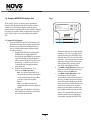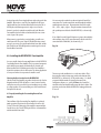
1
Renovia System
Installation Guide
ANTENNA
LEAD-IN
WIRE
GROUND
CLAMPS
ELECTRIC
SERVICE
ENTRANCE
NEC NATIONAL ELECTRICAL CODE
ANTENNA
DISCHARGE UNIT
NEC SECTION
810-20
GROUNDING
CONDUCTORS
GROUND CLAMPS
POWER SERVICE
GROUPING ELECTRODE
SYSTEM NEC ART 250
PART H
SAFETY NOTE:
Where the MAINS plug or appliance coupler is
used as the disconnect device shall remain
readily operalbe.
IMPORTANT SAFETY INSTRUCTIONS
1.
ENGLISH
2.
Danger
Exposure to extremely high noise levels may cause a permanent
hearing loss. Individuals vary considerably to noise induced hearing
loss but nearly everyone will lose some hearing if exposed to sufficiently
intense noise for a sufficient time. The U.S. Government's
Occupational Safety and Health Administration (OSHA) has specified
the following permissible noise level exposures:
3.
4.
5.
DURATION PER DAY (HOURS) 8 6 4 3 2 1
SOUND LEVEL (dB)
90 93 95 97 100 103
According to OSHA, any exposure in the above permissible limits could
result in some hearing loss. Ear plugs or protectors in the ear canal or over
the ears must be worn when operating this amplification system in order to
prevent a permanent hearing loss. If exposure in excess of the limits as
put forth above, to insure against potentially harmful exposure to high
sound pressure levels, it is recommended that all persons exposed to
equipment capable of inducing high sound pressure levels, such as this
amplification system, be protected by hearing protectors while this unit is in
operation.
CAUTION
RISK OF ELECTRIC SHOCK
DO NOT OPEN
5.
6.
7.
8.
9.
10.
CAUTION: TO REDUCE THE RISK OF ELECTRIC SHOCK, DO
NOT REMOVE CHASSIS. NO USER-SERVICEABLE
PARTS INSIDE. REFER SERVICING TO QUALIFIED
SERVICE PERSONNEL.
11 .
12.
AVIS: RISQUE DE CHOC ELECTRIQUE-NE PAS OUVRIR.
THIS SYMBOL IS INTENDED TO ALERT THE USER TO THE PRESENCE
OF NON-INSULATED "DANGEROUS VOLTAGE" WITHIN THE
PRODUCT'S ENCLOSURE THAT MAY BE OF SUFFICIENT MAGNITUDE
TO CONSTITUTE A RISK OF ELECTRIC SHOCK TO PERSONS.
THIS SYMBOL IS INTENDED TO ALERT THE USER TO THE PRESENCE
OF IMPORTANT OPERATING AND MAINTENANCE (SERVICING)
INSTRUCTIONS IN THE LITERATURE ACCOMPANYING THE UNIT.
APPARATUS SHALL NOT BE EXPOSED TO DRIPPING OR SPLASHING
AND THAT NO OBJECTS FILLED WITH LIQUIDS, SUCH AS VASES,
SHALL BE PLACED ON THE APPARATUS.
13.
14.
15.
16.
Read all safety and operating instructions before using this
product.
All safety and operating instructions should be kept for future
reference.
Read and understand all warnings listed on the operating
instructions.
Follow all operating instructions to operate this product.
Renovia Zone Amplifier components are only UL-certified when
connected to three-wire (safety grounded) electrical circuits.
Installation on two-wire circuits (no safety ground) should never be
performed as this introduces a risk of electric shock to installers
and users. Installation must be performed in accordance with all
national and local electrical codes, and should only be performed
by a properly licensed electrician.
This product should not be used near water, i.e. bathtub, sink,
swimming pool, wet basement, etc.
Only use dry cloth to clean this product.
Do not block any ventilation openings, It should not be placed flat
against a wall or placed in a built-in enclosure that will impede the
flow of cooling air.
Do not install this product near any heat sources ; such as,
radiators, heat registers, stove or other apparatus (including heat
producing amplifiers) that produce heat.
Do not defeat the safety purpose of the polarized or grounding-type
plug. A polarized plug has two blades with one wider than the
other. A grounding-type plug has two blades and a third grounding
prong. The wide blade or the third prong are provided for your
safety. If the provided plug does not fit into your outlet, consult an
electrician for replacement of the obsolete outlet.
Protect the power cord being walked on or pinched, particularly at
plugs, convenience receptacles and the point where they exit from
the apparatus. Do not break the ground pin of the power supply
cord.
Only use attachments specified by the manufacturer.
Use only with the cart, stand, tripod, bracket, or table specified by
the manufacturer or sold with the apparatus. When a cart is used,
use caution when moving cart/apparatus combination to avoid
injury from tip-over.
Unplug this apparatus during lightning storms or when unused for
long periods of time.
Care should be taken so that objects do not fall and liquids are not
spilled into the unit through the ventilation ports or any other
openings.
Refer all servicing to qualified service personnel. Servicing is
required when the apparatus has been damaged in any way; such
as, power-supply cord or plug is damaged, liquid has been spilled
or objects have fallen into the apparatus, the apparatus has been
exposed to rain or moisture, does not operate normally or has
been dropped.
WARNING: To reduce the risk of fire or electric shock, do not
expose this apparatus to rain or moisture.
FRENCH
Danger
L‘exposition a des niveaux eleves de bruit peut provoquer une perte
permanente de l’audition, Chaque organisme humain reagit
differemment quant a la perte de l’audition, mais quasiment tout le
monde subit une diminution de I’acuite auditive lors d’une exposition
suffisamment longue au bruit intense. Les autorites competentes en
reglementation de bruit ont defini les expositions tolerees aux niveaux
de bruits:
DURE EN HEURES PAR JOUR
8 6 4 3 2 1
INIVEAU SONORE CONTINU EN dB
90 93 95 97 100 103
Selon les autorites, toute exposition dans les limites citees ci-dessus,
peuvent provoquer certaines pertes d’audition. Des bouchons ou
protections dans l’appareil auditif ou sur l’oreille doivent etre portes lors
de l’utilisation de ce systeme d’amplification afin de prevenir le risque
de perte permanente de l’audition, Dans le cas d’expositions
superieures aux limites precitees il est recommande, afin de se
premunir contre les expositions aux pressions acoustiquese I evees
potentielIement dangeure u ses, aux personnes exposees aux
equipements capables de delivrer de telles puissances, tels ce
systeme d’amplification en fonctionnement, de proteger l’appareil
auditif.
ATTENTION
RISQUE DE CHOC ELECTRIQUE
NE PAS OUVRIR.
ATTENTION: AFIN DE LlMlTER LE RISQUE DE CHO ELECTR/QUE, NE
PAS ENLEVER LE CHASSIS. NE CONTIENT PAS DE
PIECES POUVANT ETRE REPAREE PAR L’UTILISATEUR.
CONFER LE SERVICE APRES-VENTE AUX
REPARATEURS
CE SYMBOLE A POUR BUT D'AVERTIR L'UTILISATEUR DE LA PRESENCE
DE VOLTAGE DANGEREUX NON-ISOLE A L'INTERIEUR DE CE PRODUIT
QUI PEUT ETRE DE PUISSANCE SUFFISAMMENT IMPORTANTE POUR
PROVOQUER UN CHOC ELECTRIQUE AUX PERSONNES.
CE SYMBOLE A POUR BUT D'AVERTIR L'UTILISATEUR DE LA PRESENCE
D'INSTRUCTIONS D'UTILISATION ET DE MAINTENANCE DANS LES
DOCUMENTS FOURNIS AVEC CE PRODUIT.
AFIN DE REDUIRE LES RISQUÉ D'INCENDIE ET DE DECHARGE
ELECTRIQUE, NE PAS EXPOSER CET APPAREIL A LA PLUIE OU A
L'HUMIDITE.
IMPORTANTES INSTRUCTIONS DE SECURITE
1. Lire avec attention toutes les recommandations et précautions
d'emploi avant d'utiliser ce produit.
2. Toutes les recommandations et précautions d'emploi doivent être
conservées afin de pouvoir s'y reporter si nécessaire.
3. Lire et comprendre tous les avertissements énumérés dans les
précautions d'emploi.
4. Suivre toutes les précautions d'emploi pour utiliser ce produit.
5. Amplificateur de Zone Renovia composants est uniquement lorsque
certifiés UL connecté à trois fils (sécurité fondée) des circuits
électriques. Installation sur deux fils circuits (aucun motif de sécurité)
ne doit être effectuée comme cela introduit un risque de choc
électrique aux installateurs et aux utilisateurs. Installation doit être
effectuée conformément aux dispositions de tous les codes
électriques nationaux et locaux et ne doit être effectuée par un
électricien correctement sous licence.
6. Ce produit ne doit pas être utilisé près d'eau, comme par exemple
baignoires, éviers, piscine, sous-sol humides ... Etc.7. Utiliser
exclusivement un chiffon sec pour nettoyer ce produit.
7. Ne bloquér aucune ouverture de ventilation. Ne pas placer le produit
tout contre un mur ou dans une enceinte fernée, cela gênerait le flux
d'air nécessaire au refroidissement.
8. Ne pas placer le produit près de toute source de chaeur telle que
radiateurs, arrivées d'air chaud, fourneaux ou autres appareils
générant de la chaleur (incluant les amplificateurs producteurs de
chaleur) .
9. Ne pas négliger la sécurité que procure un branchement polarisé ou
avec raccordement à la terre, Un branchement polarisé comprend
deux fiches dont l'une est plus large que l'autre. Un branchement à
la terre comprend deux fiches plus une troisième reliée à la terre. Si
la fiche secteur fournie ne s'insert pas dans votre prise de courant.
consulter un 'électricien afin de remplacer votre prise obsolète.
10. Protéger le cordon d'alimentation de tout écrasement ou pincement,
particulièrement au niveau des fiches, des réceptacles utilisés et à
l'endroit de sortie de l'appareil. Ne pas casser la fiche de terre du
cordon d'alimentation.
11. Utiliser uniquement les accessoires spécifiés par le constructeur.
12. Utiliser uniquement avec le chariot de transport, le support, le
trépied, la console ou la table spécifiés par le constructeur ou
vendus avec l'appareil. Lors de l'utilisation d'un chariot, bouger avec
précaution l'ensemble chariotlappareil afin d'éviter les dommages
d'un renversement.
13 Débrancher cet appareil lors d'orages ou s'il n'est pas utilisé
pendant une longue période.
14. Des précautions doivent être prises afin qu'aucun objet ne tombe et
qu'aucun liquide ne se répande à l'intérieur de l'appareil par les
orifics de ventilation ou n'importe quelle autre ouverture.
15. Pour toutes interventions techniques s'adresser à un technicien
qualifié.L'intervention technique est nécessaire lorsque l'appareil a
été endommagé de n'importe quelle façon, comme par exemple si le
cordon secteur ou sa fiche sont détériorés,si du liquide a coulé ou si
des objets sont tombés à l'intérieur de l'apparei1,si l'appareil a été
exposé à la pluie ou à l'humidité, s'il ne fonctionne pas normalement
ou s'il est tombé.
16. ATTENTI0N:Pour réduire le risque d'incendie ou de choc electrique
ne pas exposer l'appareil à la pluie ou à l'humidité.
Renovia Quick Start Guide
1. Test site with the SAT tool.
a. Determine desired location for Renovia Hub.
b. Connect filters to known Renovia enemies. (I.E. surge strips, cell phone chargers etc. Do not place filters on
the SAT! See page 11)
c. Test desired Zone locations with SAT. (See pages 10-13)
d. Use zones that test marginal or preferably use only “good” locations!
e. If all zones test marginal or less, try testing a different hub location, or look for electronics plugged into the same
outlet or adjacent outlets to the hub. These devices should be filtered.
2. Install Renovia Source Hub and Source devices.
a. Install the NV-RVM Renovia Source Hub in the pre-tested outlet; plug the power cable in to accomplish this. (Note: the
hub cannot be plugged into a surge strip as it interferes with Renovia, Renovia has built-in surge suppression)
b. Install all source components using the appropriate inputs on the Source Hub. (See pages 14-16)
3. Program Renovia Hub.
a. Program the Renovia Source Hub using the Renovia configuration software and a USB cable. (See pages 20-31)
b. Source devices programmed into the Source Hub will not appear on the system Control Pads until the source device
audio connection has been plugged in.
4. Install speakers and control options.
a. Run speaker wire and Cat5 to double gang wall receptacle located next to a tested electrical outlet.
b. CAT5 is not required if you are using a wireless control pad or a third party control option.
c. A single Zone amp can power 2 pairs of 8-ohm speakers. For this feature you must program the zone to be 4 ohm
stable. (See page 28- 29)
5. Install the Renovia NV-RVZA50PS power supplies and NV-RVZA50 zone amplifiers.
a. Connect the NV-RVZA50PS to the tested outlet. A certified electrician will be required to perform this task. A dual
gang cutout should be made in the same stud space as the zones associated outlet. A combination high/low voltage
box will also be required, and installed into the cutout. (See page 17)
b. Pull the CAT5 and speaker wire out of the low voltage portion of the combination box and connect them to the NVRVZA50 zone amp. (See page 18)
c. Install the NV-RVZA50 zone amp over the installed power supply and secure it with the four provided installation
screws.
d. Select the appropriate zone number on the rotary switch for the zone. (See page 18)
6. Install the Renovia NV-RVZAF50S Freestanding Zone Amplifiers.
a. Plug the NVRVZAF50S into its desired outlet and look for the Power LED.
b. Pull the CAT5 and speaker wire to the amplifier location and make the appropriate terminations. (See page 19)
d. Select the appropriate zone number on the rotary switch for the zone. (See page 19)
Table of Contents
Introduction
NV-RVM Main Source Hub Front Panel Features
NV-RVM Main Source Hub Back Panel Features
NV-I8GCP Dual Gang Control Pad Features
NV-E6GCP Single Gang Control Pad Features
NV-CTP36 Color Touch Pad Features
NV-WCP Wireless Control Pad Features
1.0. Using the NV-RVSAT Site Survey Tool
1.1 Suggested Test Sequence
1.2 Maximize the Probability Success
1.3 Identify Rooms for Each Zone and Outlets
1.4 Test the Candidate Outlets in Each Room
1.5 Optional Test Cleanup
1.6 Final SAT.log File
1.7 The NV-HPNF HomePlug Noise Filter
2.0. Installing the NV-RVM Renovia Main Source Hub and Audio Sources
2.1 Connecting IR Controlled Sources
2.2 Installing NuVoNet Sources with the Renovia Main Source Hub
3.0. Installing the NV-RVZA50S Zone Amplifier and Power Supply
3.1 Properly Installing the Renovia Power Supply
3.2 Properly Installing the NV-RVZA50 In-wall Zone Amplifier
4.0 Installing the NV-RVZAF50S Zone Amplifier
4.1 Properly Installing the Freestanding Renovia Zone Amplifier
5.0 Setting the Zone HomePlug Channel
5.1 Final Installed System Performance Check
6.0. Using the Configurator Software
6.1. Main Startup
6.2. IR Library
6.3. Sources
6.4. Macros
6.5. Zones
6.6. System Settings
6.7. Update System
7.0. Control Pad Setup
7.1 Factory-new Installation
7.2 Reprogramming the Zone Address
7.3 Installing the Wireless Control Pad
7.4 Renovia Tuner Control
8.0. Using the Control Pad’s MENU Button
8.1 Favorites
8.2 Sources
8.3 Tuner Options
8.4 Advanced Zone Control
8.5 Zone Settings
8.6 Advanced Zone Settings
8.7 Source Settings
8.8 System Settings
9.0 . Renovia Accessories
9.1 NV-I8DLS IR Learning Station Interface
9.2 NV-MI1 Mute Interrupt Adapter
9.3 NV-GRC1 Remote control
Page 3
Page 4
Page 5
Page 6
Page 7
Page 8
Page 9
Page 47
Page 49
Page 50
Renovia Specifications
Troubleshooting
Page 51
Page 52
Page 10
Page 11
Page 11
Page 11
Page 13
Page 13
Page 13
Page 14
Page 14
Page 17
Page 17
Page 19
Page 20
Page 21
Page 22
Page 22
Page 26
Page 27
Page 29
Page 31
Page 33
Page 34
Page 34
Page 35
Page 36
Page 37
Page 37
Page 38
Page 41
Page 42
Page 43
Page 44
Page 44
Introduction
About Home Plug Technology
The Renovia System brings the best of NuVoNet audio control to the existing home market in a dramatic way. At the heart of the Renovia System's
operation is HomePlug® 1.0 Plus technology. A consortium of large CE Industry companies known as the HomePlug Alliance created the HomePlug
Powerline communication standard EIA/TIA 1113. This initially enabled Ethernet communication over existing AC powerline wiring. The
breakthrough of this development is the ability to extend serial digital data communication without the labor-intensive task of running additional
network wiring through an existing structure.
The basis of HomePlug's success is its utilization of a relatively high signal frequency spectrum (2 – 30 MHZ for Renovia’s HomePlug version 1.0 Plus
transmission scheme) enabling communication in the presence of strong lower frequency noise disturbances created by electrical appliances fed by
AC power from the same cable. By isolating high frequency signal transmission from low frequency electrical power and load disturbances, a
standard residential electrical supply cable can be used in the same way as multi-conductor network wiring. Thus, the daunting task of routing
multiple wires through an existing multi-zone installation is no longer an issue.
Since 2002, this technology has grown into a robust communication technology that enables reliable transmission of NuVo's source metadata and
audio signals to multiple zones. After all, it is the use of an always-present wire, whether it is CAT5 and speaker wire or the AC power line, that
ensures a pleasant, uninterrupted user experience. Through the use of HomePlug, it is complete audio source control and quality sound
reproduction throughout the home that defines the lifestyle - enhancing Renovia experience.
NV-RVZAF50S Freestanding
Zone Amplifier
TOP
Model NV-RVZA50
RENOVIA Zone Amp 50 Watt
PWR RST
4567
112
12 3
ZONE
AUDIO STREAM
CONTROL
89101
NV-RVZA50S In-wall
Zone Amplifier
Diagram shown with the NuVo Music Port and Renovia
NuVoDock for iPod as sources.
B
A
USB
USB
ETHERNET
Passthrough
RS232
To NuVo
RS232
NuVoNet
C
R
R
AUDIO
SYSTEM
30 33 118
CO NF OR MS TO UL
ST D. 60 06 5 CE RTIF IE D
TO CAN /C SA ST D.
C2 2. 2 No .6 00 65 :0 6
3
D
L
L
MODEL NV-MPS4
Music Port Server
STANDBY
NV-RVM
AUDIO
STREAM
CTL
TX
NuVoNet
CTL
RX
USB
RENOVIA Main Main Source Hub
RADIO DATA SYSTEM
POWER
1
2
3
4
5
6
7
NV-RVM Main Main Source Hub Front Panel Features
1. Power Button: This button activates the internal circuitry of the Main Main Source Hub. The NV-RVM is designed to be left in the On position.
It will remain in standby when not in use. Switch off when leaving the system unused for long periods of time, such as vacation periods, in
order to avoid unnecessary power drain.
Features behind the hideaway hinged maintenance cover:
2. Standby LED: This red LED (light emitting diode), will remain lit when the NV-RVM is powered on and no zones are in use.
3. Audio Stream LED: This blue LED is a diagnostic tool. It will light while audio is streaming from the NV-RVM to any active zones.
4. Control TX LED: This green LED is a diagnostic tool indicating the transmission of control messaging from the NV-RVM to any active
zones.
5. Control RX LED: Like the Control TX LED, this yellow LED is intended as a diagnostic that will light when control messaging is being received
from an active zone.
6. NuVoNet Port: This RJ45 port supports bidirectional communication between the NuVo source components, optional Hub-connected zone
Control Pad(s,) and the NV-RVM . The front panel connection is intended to be used for temporary connection of NuVoNet devices during
installation and maintenance operations. Permanent connections are located on the back panel.
7. USB: The NV-RVM completed system configuration is downloaded from a computer running the Renovia Configurator software to the Main
Source Hub using a USB cable and this jack. In this same operation, firmware updates for all NuVo system components, including connected
NuVo source components, are also delivered via this USB port.
4
30 33 118
CO NF OR MS TO UL
ST D. 60 06 5 CE RTIF IE D
TO CAN /C SA ST D.
C2 2. 2 No .6 00 65 :0 6
/PAGE
1
2
3
4
5
6
7
8
9 10
11
NV-RVM Main Source Hub Back Panel Features
1. System On: This mono 3.5 mm voltage output is designed to emit 5 volts (no-load) when a zone is turned on.
2. IR Outputs: This IR (infrared) section is used to output IR commands sent by the Hub processor in response to button push events on zone Control
Pads. The command signals drive IR emitters connected to these outputs, which output IR commands to non-NuVoNet components. The Renovia
Configurator software can be used to design specific macro preset choices available from the Control Pad menu, see Section 6.4 Using the
Configurator Software, Macros. The Renovia System will not repeat manufacturer's remote commands from a Zone location to the Hub across
the Powerline.
3. Mute/Page: The Mute input is a trigger that will respond to the MI1 Mute Interrupt accessory to mute the system for the phone or doorbell, or it
can be set to respond to a phone paging system to trigger and amplify an externally-sourced whole house page or doorbell chime signal.
4. RS232: This port allows an optional DB9 connection for bidirectional system control from a third party home automation system.
5. NuVoNet: Three RJ45 connections are provided to allow communication with the NuVoNet source components via a CAT5 wire.
6. Antenna: The NV-RVM Main Source Hub has two built-in AM/FM tuners. These default as sources 1 and 2. This coaxial connection is designed to
receive both the AM and FM signals remotely from the included NV-T2FAA active AM/FM antenna.
7. Source Inputs: These six stereo 3.5 mm inputs will receive the audio signal from any attached source. All six can be either NuVoNet or third party
IR controlled components. Sources plugged into the 1 & 2 audio inputs will automatically override the internal AM/FM tuners. A connection to
source inputs 3 and 4 will be overridden if a Renovia NuVoDock for iPod is connected to the corresponding inputs (see item 9). Any of the sources 36 for which no connection is made (3.5 mm inputs or iPod input) will automatically be disabled for user selection.
8. SIRIUS Inputs: The source 1 and 2 AM/FM tuners can also receive SIRIUS Satellite Radio when a SIRIUS tuner device such as the NV-SCH1
SiriusConnectTM Module is plugged into this jack with the included 8 pin cable. Note that SIRIUS reception requires an appropriate antenna, see
Section 2.2.2, Adding the NV-SCHS or other Sirius Connect tuner devices.
9. iPod Inputs: iPod inputs 3 and 4 are designed to interface with the Renovia NuVoDock for iPod. A single 9-pin connection automatically provides
full metadata and audio to each of the Renovia zones when an iPod is seated in the NuVoDock.
10. Aux. Out: Renovia has an optional Zone 16 preamp lineout with fixed output level. This 3.5 mm stereo output serves as an additional zone output
for a home theater receiver, or a zone specific stereo receiver. Source selection to this output is accomplished with a Control Pad programmed to
address 16 (a “virtual” zone address assignment). Volume adjustments on this Control Pad will have no effect on the output volume, making this
output ideally suited to drive an external stereo receiver.
11. AC Power: The NV-RVM AC power cord serves a dual purpose. As with any audio component, it provides power for operation, but it also supports
the powerline network connection to each of the audio zones for both the audio signal and source metadata.
5
1
13
2
3:09 PM
SVR
1 of 9
Follow the Day
12
drift
Edge of Tomorr
3
1:28
3:48
11
4
MENU
OK
5
10
6
7
8
9
NV-I8GCP Dual Gang Control Pad Features
1. Source Indicator: This indicates the current audio source playing in that zone. Source names can be customized in the Configurator Software
with a three character designation.
2. Cover Plate: Each Control Pad comes with white, ivory, almond, and black trim plates that attach magnetically to the face of the Control Pad.
Additional styles of trim plates are available from NuVo.
3. OLED Display: The Organic Light Emitting Diode display is a highly functional eight line display.
4. Now Playing/Menu Display: This portion of the display serves two functions. In normal operation, it indicates the artist, station, metadata,
and other source information. In Menu mode it uses a smaller font to display multiple lines of information for control or browsing purposes.
5. Playback Status/Volume Level Indicator: This bar graph indicates the playback status of digital music files from music playback source
devices such as the Music Port, or NuVoDocks for iPod. The same bar graph display temporarily supports volume level display whenever a
volume adjustment is being made.
6. Menu: Menu serves as access to music browsing, presets, and favorites, as well as specific zone and system control operations.
7. Power: This button turns the local zone on and off, or turns all zones off simultaneously.
8. Play/ Pause: This IR programmable button toggles between the play and pause functions of the chosen source. When using the internal
Renovia Tuners, this button toggles through the receive modes. A third “press and hold” IR function can also be assigned to this button.
9. OK: The OK button also serves a dual function. In normal play mode, it sequences through the available audio sources. In menu mode, it is
used to select the highlighted menu item.
10. Arrow Up and Down: These arrows have dual functions. In normal play mode, they control volume level up and down. In menu mode, they
scroll up and down through menu selections.
11. IR Receiver: The Control Pad’s IR receiver will receive commands from the NuVo NV-GRC1 handheld remote control, but it will not repeat
commands from a third party IR remote control.
12. Forward/Reverse: This is an IR programmable button for simple source transport. Typically it would track forward and back or tune up and
down. A third “press and hold” function can also be assigned to this button.
13. Current Time: A feature of the Renovia System is the ability to display the current time on each of the Control Pads.
6
1
2
M3A
2 OF 2-Follow th...
drift-Edge of Tom
3
3:48
1:19
12
4
11
5
10
6
9
7
8
NV-E6GCP Single Gang Control Pad Features
1. Source Indicator: This indicates the current audio source playing in that zone. Source names can be customized in the Configurator Software
with a three-character designation.
2. Wall Plate: Each Control Pad comes with white, ivory, almond, and black trim plates that offer a screwless and elegant, finished installation.
3. OLED Display: The Organic Light Emitting Diode display is a highly functional and vivid multi-line display.
4. Now Playing/Menu Display: This portion of the display serves two functions. In normal operation, it indicates the artist, station, metadata,
and other source information. In Menu mode, it displays multiple lines of information for control or browsing purposes.
5. Playback Status/Volume Level Indicator: This bar graph indicates the playback status of digital music files from music playback source
devices such as the Music Port, or NuVoDocks for iPod. The same bar graph display temporarily supports volume level display whenever a
volume adjustment is being made.
6. Power: This button turns the local zone on and off, or turns all zones off simultaneously.
7. Menu: Menu serves as access to music browsing, presets, and favorites, as well as allowing access to specific zone and system control
operations.
8. Play/Pause: This IR - programmable button toggles between the play and pause functions of the chosen source. When using the internal
Tuners, this button toggles through the Tuner's receive modes. A third “press and hold” function can also be assigned to this button for additional
functionality.
9. OK: The OK button serves a dual function. In normal play mode, it sequences through the available audio sources. In Menu mode, it is used to
select the highlighted menu item.
10. Forward/Reverse: This is an IR - programmable button for simple source transport functions. Typically, it would track forward and back or
tune up and down. A third “press and hold” function can also be assigned to this button for additional functionality.
11. Arrow Up and Down: These arrows have dual functions. In normal play mode, they control the volume level up and down. In Menu mode,
they scroll up and down through menu selections.
12. IR Receiver: The Control Pad’s IR receiver will receive commands from the NuVo NV-GRC1 handheld remote control, but it will not repeat
commands from a third party IR remote control.
7
5
4
6
7
8
9
10
3
2
1
11
12
15
14
13
NV-CTP36 Color Touch Pad Features
1. Source Display: This full color touch pad provides crucial information about the selected source, such as artist, album, track, title, frequency
or station, and metadata for AM/FM and Satellite radio. Album art is also displayed when used with the MPS4 Music Port source. When in
menu mode, the menu control choices are displayed.
2. Current Time: A time display is distributed to all the zones in the System by NuVoNet. This is set when a configuration is downloaded to the
System or it can be set in the System Menu.
3. Party Mode: This indicator will light when the system is in party mode (all zones turned on and operated from one Control Pad).
4. Exclusive Source: When this icon is lit, Exclusive Source is turned on. Exclusive Source locks out source control from other zones of the
chosen source.
5. Mute: This icon will light when the zone is temporarily muted.
6. Sleep: This icon indicates that the zone is in “Sleep” mode, which is the ability to set an audio source to play for a specified amount of time.
7. Lock: This indicates that the zone is locked. In this state, a four-digit security code is required to unlock the zone's control features.
8. Do Not Disturb: This icon indicates that the zone is set for “Do Not Disturb”. There are three Do Not Disturb choices; exclude the zone from
Party Mode, Page Mode, and/or System Mute.
9. Page: This icon will light when the system is triggered to go into “Page Mode”.
10. Menu Button: Menu serves as access to music browsing, presets, and favorites, as well as allowing access to specific zone and system
control operations.
11. Transport Functions: These function buttons represent basic source control. They change in functionality with the chosen audio source.
12. Playback Status/Volume Level Indicator: This bar graph indicates the playback status of digital music files from music playback source
devices such as the, Music Port, or NuVoDocks for iPod. The same bar graph display temporarily supports volume level display whenever a
volume adjustment is being made.
13. Volume Up and Down Buttons: These buttons increase or decreases the zone's volume.
14. Home Button: This button returns the user to the Home screen (the view shown here).
15. Power Button: This button turns power to the zone on and off. When pushed and held it will turn off all of the zones in the system.
8
7
1
2
3:09 PM
M3A
1 of 9
Follow the Day
drift
Edge of Tomorr
1:28
3:48
3
4
8
MENU
ZONE
9
5
OK
10
6
11
NV-WCPS Wireless Control Pad Features
1. Selected Source: A three-character abbreviation of the selected source appears in this portion of the Wireless Control Pad display.
2. OLED Display: The display is multi-line OLED (Organic Light Emitting Diode). It shows album, artist and track for personal music, and channel and
frequency information for broadcast music. In menu mode, the display goes to eight lines of text.
3. Playback Status/Volume Level Indicator: This bar graph indicates the playback status of digital music files from music playback source
devices such as the Music Port, or NuVoDocks for iPod. The same bar graph display temporarily supports volume level display whenever a volume
adjustment is being made.
4. Menu: Menu serves as access to music browsing, presets, and favorites, as well as allowing access to specific zone and system control operations.
5. Up and Down Arrows: These are used to scroll up and down through the menus and control volume Up and Down in normal play mode.
6. Power: This button turns the local zone on and off, or turns all zones off simultaneously.
7. Current Time and Battery Display: This reflects the current time as set up in the NuVo Renovia System. Note that it is a Renovia-only function.
It also indicates the current battery charge level.
8. Zone Button: When this button is pushed, a list of available listening zones is listed on the display. The user can change zone control by moving
the highlight to the desired zone and pressing the OK button.
9. OK: The OK button serves a dual function. In normal play mode, it sequences through the available audio sources. In Menu mode, it is used to
select the highlighted menu item.
10. Forward and Back Arrows: In NuVoNet communication, these buttons will track forward and back or tune up and down. For third-party
sources, these are IR–programmable buttons for simple source transport functions. An additional “press and hold” command can also be assigned
to this button for additional functionality (IR commands can only be assigned to buttons in the Renovia Configurator software).
11. Play/Pause: This IR–programmable button toggles between the play and pause functions of the chosen source. When using the internal Tuners,
this button toggles through the Tuner's receive modes. A third “press and hold” function can also be assigned to this button for additional
functionality.
9
Fig. 1
1.0. Using the NV-RVSAT Site Analysis Tool
The Site Analysis Tool is an essential test prior to installing the
Renovia System. All outlets and the related circuits for each zone
should be tested. This will insure that the system will operate
properly and that existing wiring will not cause signal loss. Although
PLC technology is generally effective in isolating noise and activity
on the AC wire, a proper test of each candidate outlet should be
done.
Site 1
Hub: Other
Zone: Other #1
8:56 PM
Searching. . .
Waiting for NV-RVSAT-Z
MENU
OK
RENOVIA
Site Analysis Tool, HUB
1.1. Suggested Test Sequence
1. Set up the NV-RVSAT-H Hub Test Tool (black unit) in your
first choice hub location. In choosing the room and outlet
location, pay special attention to avoiding interference
sources, or isolating them using the techniques that are
described in section 1.2.
a. Plug the NV-RVSAT-H into the oulet where the
NV-RVM will reside. Plug the NV-RVSAT-H
directly into the outlet (DO NOT use an extension
cord). When the Hub Test Tool is plugged in, it
will search for the NV-RVSAT-Z Zone Test Tool, as
shown in Fig. 1. It will discover the Zone Test
Tool when that unit is plugged into another
outlet in the home.
b. Check the Time in the top banner. If it is
incorrect, press MENU – Date/Time
Date – use up/down arrow buttons to set
the month, then press OK to go the day and
use the up/down buttons, then press OK to
go to the year and use the up/down
buttons.
Time – use a similar technique to go
through and adjust the four time digits and
AM/PM.
c. Check the rooms list in the Menu. Consider the
name for Hub room, and all zone room locations
to be included in the installation.
If additional room names are needed, attach the
USB cable to a PC, and in a text editor, edit the
rooms.dat file in the top level NV-RVSAT device
folder and add a text line for each of the added
room names. Each room name must not exceed
24 characters in length. The new room names
will be available after you write the edited
room.dat file, and unplug the USB cable.
d. Select MENU – Change Hub Room, use the arrow
buttons to select the desired room for the first
Hub choice, and press the OK button.
e. Select MENU – Change Hub Outlet, use the
arrow buttons to select the number
corresponding to your first Hub outlet choice in
this room. For numbering outlets in this choice,
and for all Zone outlet numbering, use the first
outlet to your left as you walk in the main room
entrance as #1, and increase the designated
number as you count outlets around the room,
going clockwise around to the right side of this
entrance. This system will allow you to easily
remember outlet locations corresponding to
outlet numbers logged by the NV-RVSAT tool.
10
f.
Select MENU – Increment SITE #, then select YES
and press OK. This will start a fresh analysis log
for this installation’s site analysis test.
2. Turn on possible interference sources which are
hard-wired (not connected to outlets):
a. Low voltage lighting
b. Any lighting on a dimmer
c. Check the Renovia FAQ page for other
potential interference sources
1.2. Maximize the Probability of Success
It is a good idea to identify potential interference sources before
starting the test. This will streamline the process.
1. Before any test, look at the entire house for potential
interference and treat the interference with NV-HPNF
filters. See section 1.7 The NV-HPNF HomePlug Noise
Filter. The following are good candidates to be treated
with an NV-HPNF.
a. As stated earlier in this section, electronics plugged
into high quality surge suppressors often used with
audio/video suites probably do not need filters, but
should be noted for checking with a filter if
problems are encountered later.
b. Low cost surge suppressor power strips SHOULD
have filters added.
c. Cable boxes and consumer electronics devices with
external power supplies will somtimes need filters,
if they are not already connected through high
quality surge suppressors.
d. Here is a short list of other possible plug-in
interfering items:
i. Wall power supplies
ii. Battery chargers
iii. Inexpensive clock radios and
alarm clocks
iv. Lamps with electronic dimmers,
such as touch lamps
v. Items with small, low dutycycle motors such as paper
shredders, inexpensive vacuum
cleaners,coffee grinders, electric mixers,
or electric can openers are common
interferers, but the interference is
usually confined to the zone(s) they are
close to. If it is important to hear music
while these infrequently used items are
running, filter them.
vi. Check the Renovia FAQ webpage at
nuvotechnologies.com for
an update on other potential
interference sources
1.3. Identify Rooms for Each Zone and Outlets
The key to a successful installation with minimal invasion into the
home is carefully considering the location of each outlet to be used
for Zone Amplifiers.
1. Take into account both speaker and Control Pad (if
applicable) locations. Locating them in the same stud
bay is the easiest approach.
2. The outlet used for a Zone Amp connection does not
need to be inside the room. Outlets on the other side of
a shared wall can be used while keeping the Zone Amp
inside the target room.
3. It is possible to use some light switches as an AC source
for a Zone Amp, but it is not recommended.
a. It is not possible to determine which light
switches can be used without having an electrician
examine the wiring.
b. The Site Analysis Tool cannot directly test the
performance of a Zone Amp connected to a light
switch.
4. Alternate locations should also be identified for each
Zone Amp location. Don't forget to use the
standardized outlet-numbering scheme described in
step 1(e) on page 10.
1.4. Test the candidate outlets in each zone
1. Once the NV-RVSAT-Z Zone Test Tool is plugged into a
prospective zone outlet, it will establish
communication with the Hub Test Tool, as shown in
Figure 2. If the display continues to show “Searching
…”, this means there is no signal path between your
Hub location and the outlet under test. An outlet
yielding this result should not be used.
11
Fig. 2
Fig. 3
Site 1
8:56 PM
Hub: Entertainment room #3
Zone: Other #1
Untested
Site 1
8:56 PM
Hub: Entertainment room #3
Zone: Living room #1
MENU
MENU
Stage 1
Testing. . .
OK
STR 65%
OK
100%
Press OK to Test
RE NOV IA
Si te An alysis Too l, Zo ne
RENOVIA
Site Analysis Tool, ZONE
Site 1
8:56 PM
Hub: Entertainment #1
Zone: Living room #1
Stage 2
Testing. . .
2. Select Menu – Change Room and select the zone name
for the first outlet you test in a room. Using the
standardized outlet numbering scheme described in
step 1(e) on page 10, select Menu – Change Outlet and
select the outlet number. To sequence outlet numbers
from here in the zone, simply press the Up Arrow
button to increment.
QCM 75%
MENU
OK
100%
RE NOV IA
Si te An al ys is Too l, Zo ne
3. To perform a test, make sure to complete the previous
step first, and then simply press the OK button on the
Zone Test Tool. You will see two separate tests being
performed, as shown in Fig. 3. First, in Stage 1, the
tester will perform an STR (signal streaming) test. At
the 75% complete point, this will be followed by Stage
2, CQM (channel quality matrix) test. The entire Stage
1 – Stage 2 sequence will last approximately 1 minute.
A group of several measurements will be gathered from
these tests and evaluated together to produce a
displayed result – Good, Marginal, or Poor along with a
percentage score ranging from 0 to 100%, as shown in
Fig. 4. Any grade below 60% is Poor. 60 to 69% is
Marginal and 70 to 100% is Good. Any outlet that
shows a Good rating is an excellent choice for the
installation of a Renovia Zone Amplifier.
Fig. 4
Site 1
8: 5 6 P M
Hub: Entertainment room #3
Zone: Living room #1
Good
Grade: 80%
MENU
OK
Press OK to Test
RENOVIA
Site Analysis Tool, HUB
Site 1
8:56 PM
Hub: Entertainment room #3
Zone: Living room #1
Good
Grade: 80%
OK
Press OK to Test
If at all possible, avoid Poor outlets and
minimize the use of those that test Marginal.
RENOVIA
Site Analysis Tool, ZONE
12
MENU
3. Finally, check every Zone Amp location outlet NOT
covered in step 1.4.5 one more time to make sure
subtracting filters has not adversely affected your
previous results.
4. If a highly desirable outlet tests Poor or Marginal, look
again for possible unfiltered Interference sources. They
are normally on the same circuit, but may be in other
rooms. Unplug the suspect device, run the test, and if
the test result improves, add an NV-HPNF filter and test
again.
1.6 Final SAT.log File
Try turning off interference sources identified in step 3
which are hard-wired, and run the test. If the test
passes, check with the manufacturer of the device(s).
Some interference sources can be eliminated by
replacing or upgrading power supplies. Manufacturers
may provide free replacement.
When the NV-RVSAT-H Hub Test Tool is connected to a computer
using a USB-B cable, it will provide a log file with the test results.
Store the final SAT.log file in a job folder on the PC – it may come in
handy should you need NuVo technical support at some point. You
will want to edit the previous sites stored in this log file, so that only
the information associated with the Site Number you set for this job
is stored in that file. The Hub Test Tool will continue to append
multiple sites in the stored file until you delete it. If you delete it,
you may begin numbering sites at Site 1 again, if you like, or
continue with sequential numbers.
5. If many outlets are testing Poor or Marginal, search for
interference sources near the Hub, or reconsider an
alternate Hub location, returning to step 1. The Site
Number can remain the same to do this, as the log will
capture data for the new Hub location while keeping
storage for all results for the first Hub location intact.
1.7 The NV-HPNF HomePlug Noise Filter (120V only)
The NV-HPNF Noise Filter, as shown in Fig. 5 is a useful accessory for
isolating electrical interference from the HomePlug signal. This is
often necessary with an external MOV type power surge device
plugged into the same outlet as the Main Source Hub. Although it is
unlikely, you may encounter a particularly noisy appliance who’s
interference is easily corrected by simply plugging into the Noise
Filter and then into the desired outlet.
1.5 Optional Test Cleanup
Once the selection process has been completed for all zones, if
desired, you may want to consider a “cleanup process” to eliminate
filters you may have preemptively placed in step 1.2.
1. Connect the Hub Test Tool to a PC using the USB cable,
and open the SAT.log file in the top level NV-RVSAT
device folder using Notepad or any text editor. Print it
for reference in the next step.
Fig. 5
NV-HPNF Front
2. Go to outlets with a filter placed in step 1.2. , and run
the test again using the Zone Test Tool. Don't forget to
use the Menu to re-select the previous room name
you used, and the same outlet number. Compare the
new reading on the display to the previous reading in
the printed log. If you see no degradation in the
result, you can eliminate the filter at this point.
13
NV-HPNF Back
2.0. Installing the In-wall NV-RVM Renovia Main
Source Hub and Audio Sources
Four NV-VEC1 IR Emitters are included with the Main Source Hub.
These are intended to supply IR commands to the attached sources.
Plug the emitter into the appropriate numbered IR output in the IR
Output section of the NV-RVM. The number of the output
corresponds with the numbered input of the source being controlled.
The head of the emitter should then be attached over the IR receiver
on the source component, as shown in Fig. 6. The SUM output will
duplicate simultaneously, any and all of the IR commands active for
any of the source 1 - 6 IR outputs, each of which can be activated one
at a time.
The Renovia Main Source Hub is the central source input for all
sources associated with the Renovia System. This should be located
in an audio closet, rack or entertainment center, where the system
sources can be easily attached.
Place the Main Source Hub component in the desired location and
plug it into the AC outlet. Remember, the AC outlet from the hub
location is the audio and source metadata connection to each of the
zones.
It is important to note that the Renovia System is not
capable of receiving and sending IR commands from the
zones to the Main Source Hub through the IR receiver on the
Control Pads. IR commands can only be issued as pre-programmed
macros in the Renovia Configurator software (see Section 6.4 - Using
the Configurator Software, Macros). An IR connection is not
necessary if you are using NuVoNet Sources. Those sources will be
covered in the next section.
You should never plug the Main Source Hub into an external
surge protector device. These often inhibit HomePlug signal.
The fix for such a condition is the NV-HPNF, a Homeplug
isolator/filter device that is available from NuVo. The NV-RVM Hub has
specific MOV surge protection built in to allow it to plug directly in the
desired outlet. In addition, if you plug the Main Source Hub into an
outlet that is shared with an inexpensive surge protector device, it may
absorb Hub signals to the point that the signals are compromised. Such
a case will be made evident by testing this outlet with the NV-RVSAT-H
Hub Tester plugged in alongside the surge protector. You should never
use an extension cord with the Main Source Hub. It can degrade
your system's performance.
Fig. 6
AUDIO
OUT
COMPACT
L
R
dISC
Some higher end surge protectors, may offer very effective filtering
against Homeplug interference from certain audio/video
components found in a home entertainment center. It may not be
necessary to isolate such a surge protector with an NV-HPNF
isolator/filter device.
2.1 Connecting IR Controlled Sources
The Source Input section on the Hub's back panel has six stereo mini
3.5 mm connections for distribution of up to six IR controlled
sources. The connections do not become active on the sytem
Control Pads until a source is physically plugged in. This allows the
System to automatically reflect the available sources for the user.
2.2 Installing NuVoNet Sources with the Renovia Main
Source Hub
Although the Main Source Hub has two AM/FM/SIRIUS Ready tuners
internally as sources 1 and 2, any source plugged into the 1 and 2
inputs will override the internal tuners.
2.2.1 Source 1 and 2 Dual AM/FM/SiriusConnect Tuners
The NV-RVM features two independent AM/FM tuners with
associated SIRIUS Ready inputs for incorporating SIRIUS Satellite
Radio. These act as a default Source 1 and 2. These may be easily
disabled by plugging another line level audio source into the Source
1 and 2 stereo inputs.
14
These are easily used as sources by attaching the included NV-T2FAA
AM/FM antenna to the coaxial antenna connection using a standard
RG6 Coaxial cable, as shown in Fig. 7 If you are using a third-party
FM antenna for signal reception, you must turn off the voltage
provided by the Renovia System for AM reception. This is done from
the Advanced T2 Settings menu on the Control Pad.
Your SIRIUS Tuners must be activated through SIRIUS. This
can be done online at www.SIRIUS.com.
Receiving the satellite radio signal depends on a satellite radio
antenna. NuVo's accessory NV-T2ANT-DK is the perfect solution. It is
designed to provide a signal for up to two NV-SCH1 modules, as
shown in Fig. 9.
Fig. 8
Fig. 7
The NuVo active
antenna can be located up to
200 feet from the Main Source
Hub.
Fig. 9
TM
2.2.2 Adding the NV-SCH1 or other Sirius Connect tuner
devices
NuVo offers a SIRIUS Satellite Radio receiver module, NV-SCH1,
produced by a third-party manufacturer for SIRIUS Radio use. This
module comes with a standard 8-pin cable that supplies both the
audio and metadata associated with satellite radio broadcast. One
module is required for each tuner that you want to enable with
SIRIUS capability. This is easily added to the Renovia System by
plugging the 8-pin cable into one or both of the SIRIUS inputs on the
Main Source Hub, as shown in Fig. 8. Once the SIRIUS receiver is
activated and receiving a signal, the Renovia Main Source Hub will
recognize SIRIUS as an additional band available through Sources 1
and 2.
NV-T2SXA SIRIUS/XM outdoor
antenna.
15
NV-SCH1 SIRIUS Tuner is not
included in the NV-T2ANT-DK
package.
Fig. 10
2.2.3 Including the NV-RVIPD NuVoDock
Renovia features Source 3 and 4 inputs for the Renovia NuVoDock for
iPod. This is an easy way to incorporate iPod as a source for the
Renovia System. Plugging the included
9-pin cable into the NuVoDock and into the desired source input 3 or
4, as shown in Fig. 10, is the only setup that is required. Once
connected, any docked iPod or iPod touch music content will become
available on the system's Control Pads.
2.2.4 Using the other NuVoNet Sources with Renovia
The Remote, Wireless and Wall Mount NuVoDocks for iPod, and the
Music Port are all NuVoNet source components. When they are
connected by CAT5 cable to the Renovia System, and are capable of
providing full music library browsing and control through the
NuVoNet platform. The Control Pads configured for the Renovia
System will all display the full metadata for each source.
Fig. 11
To allow the metadata and control for the Renovia System Control
Pads, the source must have a NuVoNet CAT5 connection from its
“NuVoNet” output to one of the three “NuVoNet” inputs on the back
of the Renovia Main Source Hub. An audio connection using the
included stereo mini to RCA cables is then made to the appropriate
source inputs on the Renovia Main Source Hub. The connections do
B
A
USB
USB
ETHERNET
Passthrough
RS232
To NuVo
RS232
NuVoNet
C
R
R
SYSTEM
not become active on the sytem Control Pads until a source is
physically plugged in. This allows the System to automatically
reflect the available sources for the user. Remember, sources 1 and
2 are typically left at the default internal AM/FM tuners. This
example shows the NuVo NV-MPS4 connected to source 4, as shown
in Fig. 11. You can however, plug any source into Source 1 or 2 inputs
to override the internal tuners.
Note that each NuVoNet Source has its own method for
setting a NuVoNet Source Address for its audio outputs. It is
important for proper communication that each audio output
has an appropriate source address for the source inputs
being used. Refer to the installation instructions for the
source for more detailed instruction.
16
D
L
L
AUDIO
3.0. Installing the NV-RVZA50 Zone Amplifier and
the NV-RVZA50PS Power Supply
Fig. 12
Hot Ground Neutral
The Renovia Power Supply is to be installed by a certified
electrician only.
Choosing the Best Location for the NV-RVZA50
Any room outlet can be used as a location for the Zone Amplifier and
Power Supply. For the best performance, only use outlets that have
tested with the SAT Site Analysis Tool as Good or Marginal.
3.1 Properly Installing the Renovia Power Supply (Certified
Electrician only)
When you have decided on the outlet in the zone, cut the power to
that circuit and cut a hole for a standard dual gang-mounting box.
This needs to be a combination high voltage/low voltage box. NuVo
recommends the Arlington Industries LDVR2 box shown in Fig. 12, or
the Carlon BH234R box paired with the Carlon SCDIV divider (note
that per building code, there must be a divider between the low
voltage and high voltage components). These are both “old work”
boxes designed for drywall.
Fig. 13
Model NV-RVZA50PS
RENOVIA Zone Power Supply 50 Watt
Remove the outlet from its electrical box. Terminate a length of
three conductor electrical wire into the outlet. Keep in mind that the
outlet location does not have to physically be in the zone that the
NV-RVZA50 is serving, and that more than one NV-RVZA50 can
operate on a single outlet.
3.2 Properly Installing the NV-RVZA50 In-wall Zone Amplifier
Thread the length of electrical wire through the hole for the NVRVZA50 and into the high voltage side of the mounting box to be
installed. Install the mounting box in the wall. Use wire nuts to
connect the black (hot), white (neutral) and ground wire leads from
the Renovia Power Supply to the corresponding leads from the
electrical wire, as shown in Fig. 12. Install the Power Supply into the
high voltage side of the mounting box, as shown in Fig 13.
Connect the NV-RVM’s AC power cord at its chosen location, and
power it up. This will assist with installation of the Zone Amplifiers.
Before you install the Zone Amplifier, terminate the audio wire to
the zone speakers into the modular “Euro” connector. The proper
termination is Left -, Left +, Right -, Right +, as shown in Fig. 14.
The speakers are now ready to plug into the Zone Amplifier. There
are three choices for a wired in-wall Control Pad for zone control.
These are the single and dual gang OLED display Control Pads and
the Color Touch Pad. You will need a length of CAT5 wire from the
Zone Amplifier location to the Control Pad location with an RJ45
termination on each end. The necessary termination is the EIA/TIA
standard network 568A or 568B wiring, as shown in Fig. 15. Either
wiring will work as long as both ends of the CAT5 termination are
consistent.
Although the use of an outlet is the suggested location,
others are possible. You can use a light switch as the source
of power if the electric service is run to the switch and then
to the light fixture or anywhere there is the presence of the
hot and neutral for communication and the ground for
proper operation of the Renovia Power Supply.
17
Fig. 14
Gro
un
IR d
Ac
Gro tive
un d
Con
tr
Con ol Da
ta
tr
IR ol Da BusDa
ta B
us+
Gro ta
un d
+24
VP
ow
er
Fig. 15: EIA 568A wiring scheme for CAT5 Cable
Pin #
1. Green Stripe
2. Green
3. Orange Stripe
4. Blue
5. Blue Stripe
6. Orange
7. Brown Stripe
8. Brown
-
Note: Colors listed as “stripe” are a white wire
with a colored stripe.
LEFT RIGHT RIGHT
+
+
1 2 3 4 5 6 7 8
Pair 2
When the Power Supply is installed, installing the Zone Amplifier
section is very straightforward. A twelve position rotary switch on
the face of the Zone Amplifier component is necessary for setting a
zone address. This is done with a small screwdriver. Simply set a
number that corresponds with the zone's position in the system, as
shown in Fig. 16. Each zone must have a unique number address
setting. Install the Zone Amplifier over the existing Power Supply.
Pair 1
Pair 3
Pair 4
Wires insert from
this end.
Fig. 16
PWR RST
ZONE
A BC
Fig. 17
If an address setting conflicts with another already installed Zone
Amplifier's address, an error message will be displayed, and both
LEDs on the Zone Amplifier will flash in groups of threes. If speakers
are connected to the Zone Amplifier, groups of three warning tone
bursts will be heard simultaneously. The same Control Pad message,
and audio/flashing LED cues will occur with the previously installed
Zone Amp that has the address conflict. Simply use a screwdriver to
select a different, unused address between 1 and 8 on one of the
two Zone Amplifiers in conflict. This will clear the address fault and
the warning cues.
18
5
34 6
D12
If you are using an in-wall single, or dual gang Control Pad or the
Color Touch Pad, plug the associated CAT5 wire into the “NuVoNet”
CAT5 connection on the back of the Zone Amplifier and plug the
terminated speaker connector into the speaker output, as shown in
Fig. 17. The unused “Audio IN/OUT” RJ45 jack is for future use. It is
okay to make futher address setting adjustments after the Zone
Amplifier has been mated to the Power Supply and powered up. The
device will reset about three seconds after the switch has been set.
78
-
LEFT
Top view with
tab down.
AUDIO STREAM
CONTROL
An inset plug on the Power Supply will mate with a plug on the Zone
Amplifier. Once in place, secure the Zone Amplifier to the Power
Supply with four screws and install the finished cover plate. This is
held in place with four magnets and a single set screw on the
bottom. It can also be painted to match the wall color. When the
Zone amplifier has been addressed and installed, the zone is now
active as part of the system.
You are now ready to make the speaker and optional Control Pad
connections. The speaker connection is made through the included
modular phoenix connector. The termination is from left to right,
left – , left +, right –, right + . Plug the terminated connector into
the speaker input on the back of the NV-RVZAF50S, as shown in fig.
18.
If one of NuVo’s in-wall Control Pad options is going to be included in
the installation, then a CAT5 connection must be made at the RJ-45
connection labeled “NuVoNet”, also shown in fig. 18.
When power is restored to the associated outlet, you will see an
amber power LED. The green “Control” LED will flash when control
messages are sent to or received from the Main Source Hub, and the
blue “Audio Stream” LED will light when an audio signal is received
from the Main Source Hub.
Fig. 18
4.0. Installing the NV-RVZAF50S Zone Amplifier
An easy to install solution for zone amplification is the NV-RVZAF50S
Freestanding Renovia Zone Amplifier. This is an external component
with a built-in power supply and detachable AC electrical cord.
When installed, the Freestanding version of the Zone Amplifier is
identical in operation to the In-wall version. The obvious application
is for any zone where it is not practical to install in a wall.
Choosing the Best Location for the NV-RVZAF50S
Like the in-wall Zone Amplifier, any outlet that has tested as Good or
Marginal with the SAT Tool will suffice as a zone location. Consider
outlets that are easily accessible if you are intending to use In-wall or
in-ceiling speakers or if you are installing one of the in-wall Control
Pad options for the zone.
The next step in the installation is to set the zone address. This is
done using the multi-position rotary switch on the bottom of the
NV-RVZAF50S, as shown in fig. 19. This switch setting, 1 - 8 should
correspond with the number assigned for that zone in the
Configurator software, see section 6.5 Zones. Any Control Pad
attached to that Zone Amplifier will assume that zone’s address. This
procedure can be done with the NV-RVZAF50S unplugged from the
AC as well.
4.1 Properly Installing the Freestanding Renovia Zone
Amplifier
Fig. 19
The installation of the Freestanding Zone Amplifier is a relatively
simple operation. Plug it into the desired outlet. You will see the
“Power” LED on the leading edge of the amplifier component light.
You will also see the “Control” LED begin to flash as it communicates
with the installed Source Hub.
ZONE
A BC
78
19
5
34 6
D12
Line Input
The NV-RVFZA50S has a built-in “Line Input” on the back panel. This
is a very useful feature for allowing the internal 50W zone amplifier
to amplify any local source to the attached zone speakers, as shown
in fig. 20. This is a “smart” input and will recognize a 3.5mm mini
stereo input plug and automatically display a “Local Source”
selection on the zone controller. This enables the local source to be
selected and volume controlled from the NuVo Control Pad. The local
audio input can be set at variable as an either variable iPod, Mp3,
computer or other devices with headphone outputs. It can also be
fixed for many TV lineouts. Individual audio selections for the local
source must be made at the source. Those will not be available
through NuVoNet.
5.0 Setting the Zone HomePlug Channel
If the HomePlug Channel on the Main Source Hub has been changed
to one other than A, see section 6.6. Using the Configurator
Software, System Settings, then you must make sure that each
Zone Amplifier is set to match.
Before setting the HomePlug Channel, the desired Zone Number
must be set, (see Section 3.2 Properly installing the Renovia Zone
Amplifier or 4.1 Properly Installing the Freestanding Renovia
Zone Amplifier).
To set the HomePlug Channel, use a small screwdriver to turn the
zone address rotary switch, either clockwise or counterclockwise, to
the appropriate channel letter, A, B, C, or D as shown in Fig. 21,
showing the zone set on HomePlug channel B. Wait for the green
“Control” LED to light; then within three seconds of the green LED
turning on, turn the switch back to the desired zone number
previously set, as shown in Fig 22, showing the zone set on number
6. The Zone Amplifier will reboot. You will see the green Control LED
flash once for channel A, twice for channel B, three times for channel
C and four times for channel D. The Zone Amplifier should then
connect with the Main Source Hub and the attached Control Pad will
reinitialize.
Line/HP Output
A second 3.5mm mini stereo output is also available. This is useful as
a headphone jack particularity with tabletop or desktop
installations, as shown in fig. 21. By default, this is a variable output
for most headphone applications, or it can be switched to a fixed a
fixed output in the “Advanced Zone Settings” menu or in the “Zones”
tab of the Configurator software. The most common use for this
connection is as a lineout to an additional amplifier or receiver that
has its own volume control.
Warning: Excessive volume through a headphone device can
cause permanent damage or loss of hearing.
Note the process is the same for the NV-RVZAF50S Freestanding
Zone Amplifier using the rotary switch located on the bottom of the
amplifier. The easiest way to see the response of the Control LED is to
turn it upside-down and view it through the adjacent ventilation
holes.
Fig. 20
SPEAKER OUTPUT
LINE
INTPUT
LINE/HP
OUTPUT
You can always verify the set HomePlug Channel by using a small
screwdriver or paper clip to press the RST, Reset button located on
the NV-RVZA50 or by turning the “Power” button off and back on, on
the NV-RVZAF50S. The Control LED will flash indicating the current
channel setting, as shown in Fig. 23.
NuVoNet
100-240V~50-60Hz 50W
The Line input requires
a stereo mini connection
from the local source output
The Line/HP Output requires
a stereo mini connection for
headphones or additional
amplification.
20
5.1 Final Installed System Performance Check
Fig. 21
ZONE
D12
CONTROL
The easiest way to confirm that you have a robust installed Renovia
system is to go to the zone of your choice, and engage Party Mode
from the control device in use for that zone. First, turn on your Host
Zone, and select the music source of your choice. If you just press the
Power button and switch the zone on, Tuner 1 will come up by
default, and you may use the Play/Pause button to switch bands,
and use the << or >> buttons to tune to the station of choice.
Once this zone is playing, select Menu – Adv. Zone Control –
Party Mode. All zones will be turned on and their volume will
follow the Party Host Zone. Then, walk around and listen to music
for a few minutes in each zone to verify that the audio is playing
without gaps or stutters.
ZONE
A BC
A BC
PWR RST
AUDIO STREAM
5
34 6
5
34 6
D12
78
PWR RST
Fig. 22
AUDIO STREAM
CONTROL
78
NV-RVZA50
78
5
34 6
A BC
D12
78
A BC
ZONE
D12
5
34 6
ZONE
At this point, we strongly recommend you run a baseline test on the
system signal performance parameters. This is an easy test step that
records technical signal quality parameters that may be very
necessary for troubleshooting should your homeowner's electrical
system change significantly in the future and create problems with
audio performance in part of the system. To run this test, select
Menu – Setup – System Settings – Advanced (requires a press and
hold for six seconds) – Diagnostics – PLC Test. Any current audio
play will stop, and the system will display “Testing - Please Wait” on
all Control Pads. The test will take up to four minutes. When the test
finishes, all zones will be turned off, and the control displays will go
blank, leaving the system ready for use. The baseline performance
test results are permanently stored as a file in non-volatile memory.
If these are ever needed to assist with troubleshooting, NuVo
technical support will instruct you as to how to retrieve the file to
assist with assessing electrical system changes.
NV-RVZAF50S
Fig. 23
ZONE
PWR RST
CONTROL
78
NV-RVZA50
AUDIO STREAM
5
34 6
A BC
D12
Look for the Control LED to
flash indicating the set
HomePlug Channel.
NV-RVZAF50S
SPEAKER OUTPUT
100-240V~50-60Hz 50W
Cycle the Power button and
Look for the Control LED to
flash indicating the set
HomePlug Channel.
21
6.0. Using the Configurator Software
6.2. IR Library
6.1 Main Startup
The Start tab is the beginning point for any configuration, whether
you are starting from scratch or reusing a previously built
configuration.
6.1.1. Open or Create Renovia Configurator File (as shown in
Fig. 24)
The IR Library tab is where all source control functions are stored as
individual IR libraries. This section covers adding new components,
testing codes and assigning function buttons on the Control Pads.
When you click on this button, the program goes to a Config. File.
There you can either open one of the existing configurations or
specify the name of a new file. Configurations are saved with a .cfg
extension.
6.1.2 Retrieve Configuration from Renovia
6.2.1 IR Libraries (as shown in Fig. 25)
The IR Library is a list of available components and their IR function
codes. The Configurator Software stores captured IR codes in a single
directory. Once captured or downloaded, the Configurator Software
will permanently store it as an .irc file.
Fig. 25
To retrieve a configuration from an existing Renovia installation,
launch the Configurator Software. Make sure your computer is
connected to the USB port on the front panel of the Renovia Main
Source Hub. The Startup screen has two buttons. The first is used to
open an existing configuration or to create a new one. The second
asks to “Retrieve Existing Configuration From Renovia.” When you
click on the “Retrieve” button, a progress window will appear.
If you have this configuration already stored on your computer's hard
drive, you will see a dialog box asking if you wish to overwrite the
existing file. If this file is not stored in your computer, this box will
not appear.
Fig. 24
22
6.2.2 Adding a New Component to the IR Library (as shown
in Fig. 26)
The back panel of the Interface box has two IR outputs for testing
purposes. You can use the included IR emitter and attach it to the IR
window on the face of the source component or to the built-in IR
blaster, which, when aimed at the source equipment, will fire the IR
command.
New component IR files are easily added by clicking on the “Add
New” button. This brings up a new window titled “Add New
Component”. In this window, you must first enter the manufacturer
name and model. The “Make” field defines the manufacturer of the
equipment. A drop-down menu allows you to choose a
manufacturer from the IR Library. Type the model number in the
“Model” field. The Type drop-down menu contains a large list of
components. Each is a template of common functions for that type of
equipment. Clicking on the type that matches the component will
add the type name in that field. If desired, you can add a type name
that is not listed in the drop-down menu.
Fig. 27
+
-
POWER
12VDC/0.4A
Clicking on OK will automatically add the selected component and
associated functions to the IR Library.
CONNECT TO
CONCERTO D
CONNECT TO
PC
IR
EMITTER
IR
BLASTER
Concerto Learning Station
Model NV-I8DLS
PASSTHRU
READY
IR SENSOR
TEST ACTIVE
POWER
Fig. 26
6.2.4 Recording IR codes (as shown in Fig. 28)
When a new component is added to the IR Library, it is necessary to
record the IR codes associated with each function. To do this, connect
the Learning Station Interface as described above. Double-click on
the desired component from the IR Library page. This will open the
IR Library Editor. This window lists the complete set of functions for
that type of device.
6.2.3 Using the NV-I8DLS IR Learning Station Interface (as
shown in Fig. 27)
To initiate the IR recording process, you can either double-click on a
function to be recorded or highlight the function and click on the
Record button. This will open the IR Library Record window. The
window will indicate that the Configurator is “Waiting for IR
Communications.” To record a new code, simply point the
component's remote control at the IR receiver on the NuVo IR
Learning Station Interface. The first time you enter a code, the
Configurator determines if it is a “toggling function,” which means
that the remote sends two commands back-to-back. This requires
that the function button be pressed four times in succession.
To record new IR codes, you will need the IR Learning Station
Interface. This is a powerful tool for setting up new IR Libraries for
use with the Configurator Software, and is part of the IR Learning
Station package. Capturing function codes and adding them to the
component IR Library is an easy process.
The Interface box is connected to your computer using one of the
RS232 connection cables, provided with the IR Learning Station
package. Note that in many cases, personal notebook computers do
not have a Db9 serial cable. In this case an RS232 to USB dongle
cable will be necessary.
23
Fig. 28
To assign default IR functions to the Control Pad buttons, right-click
on each code and select “Keys.” This opens a drop-down menu of the
possible key selections for the Control Pad. Select the appropriate
key for that command and the Configurator will add it to the Default
Key field for that command. The Play/Pause, Prev. and Next
functions have an additional (Held) function. This allows any code to
be added as an additional function assignment that is activated
when the button is held. The Control Pad automatically displays the
function being sent to the source component.
Once this sequence is completed, proceed to the next function
command and repeat the above steps. When you have assigned a
default key for each IR, click “Done” and that component's IR Library
is complete.
When the remote code is entered, the IR Library Record window will
go from yellow to green and indicate that the capture was
successful, then return to yellow. Repeat this procedure three more
times until the desired code is added to the IR Library Edit window.
You will now see the number of code repeats and the duration of the
code. A normal non-toggling remote will require two button pushes
to successfully record a command, while a toggling remote will
require four button pushes for each command.
You can also assign discrete Power On and Off commands. The
Renovia System will initiate the On command when a zone is turned
on and the Off command when the zone All Off function (holding
the Power button for three seconds) is performed from any of the
Control Pads.
Fig. 29
If there is an error in recording the code, the display in the Record
window will indicate that there was a communication error. If this
occurs, click on the Record button and reenter the code.
6.2.5 IR Library Default Key Assignment (as shown in Fig. 29)
Once the desired codes are added, assign them to the appropriate
key on the Control Pad. Note that by design, the Control Pad has only
3 IR programmable function keys and Power On/Power Off. Access to
multiple preset choices will be covered later in the Macros section
(see Section 6.4, Macros).
24
6.2.6 IR Library Test (as shown in Fig. 30)
6.2.7 Adding a Function Code (as shown in Fig. 31)
An important feature of the Renovia Configurator is the ability to
test each IR code as it is added to the IR Library. This insures that
every code will work reliably.
If a required IR function is not in the list of those provided in the
library template, it is possible to add a code to the list by clicking the
“Create New” button. The pull-down menu contains a list of all
standard IR codes. A name not found in the list can be typed in, but
it is recommended that you use the names provided in the list. This
conserves memory. Clicking on the “OK” button proceeds directly to
the IR recording process.
When a new code is added, while it is still highlighted, click on the
test button, or double-click on the highlighted code. This will open
the IR Library Test window. Make sure the IR Learning Station
Interface box's IR emitter is either facing the IR receiver window of
the source equipment (check the box labeled “Use Blaster Output”),
or an IR emitter is plugged into one of the two IR emitter outputs
and affixed to the IR receiver window of the source equipment.
Clicking on the test button will cause the IR Learning Station
Interface to emit the code. The source equipment should respond
appropriately to the command if it has been stored correctly. A test
result box will open where you can record yes or no to the test. Three
successful test results are required before the “Passed” count turns
green. Clicking the “OK” button will save the results in the IR Library.
The “Tested” column for that command will show the number of
successful tests performed.
Fig. 31
Although not required, testing each code is
highly recommended.
Fig. 30
6.2.8 Cleaning Up an IR Library
Unused IR codes can be deleted from the list by highlighting the
code and either clicking the ”Delete” button or right-clicking and
selecting “Delete.”
When you are finished editing the library, select “Done.”
25
6.3. Sources Tab (as shown in Fig. 32)
The “Sources” tab allows you to define the source component
attached to each of the six source inputs. All six sources are not
needed. If none are defined in the configuration, the configuration
will initialize and the Hub firmware will default to two activated
sources, the internal AM/FM/SIRIUS–Ready Tuners on on the Source
1 and 2 inputs. It should be noted that the Hub will not activate any
of the sources 3 - 6 for selection that do not have audio cables
connected, even if they are defined in the configuration that is
loaded.
6.3.1 Select or Edit Source (as shown in Fig. 33)
Double-clicking on a blank source will open the “Select Source”
window. This window assigns the appropriate source number input.
The “Display Name” is the text that will be read on the Control Pad
when that source is selected in any zone. The display name can
contain only capital letters, numbers, and some punctuation. If an
invalid key is typed, it will be ignored. The “Short Name” field is for a
three character abbreviation that will be used to identify the source
on the Control Pad display.
All that is necessary for tuner reception is to attach the included NVT2FAA active antenna to the Antenna input on the Main Source Hub.
These however, can be used for other sources connected to the
stereo mini 3.5mm jacks on the back panel, if you choose. Highlight
either of the sources and delete them by clicking on the Clear
button. This will allow you to add any other source you choose from
your IR Library (See Section 6.3.1 Select or Edit Source).
An important feature of the “Select Source” window is the “Gain”
level control. Different pieces of source equipment tend to have
different levels of audio output signal. This slider control allows you
to compensate for equipment that has an inherently lower volume
level. By using this adjustment, when switching between sources,
relative volume levels remain constant.
Source 3 and 4 default to the 9-pin inputs for the NV-RVIPD Renovia
NuVoDock for iPod. These however, can be used for other sources if
you choose.
When the appropriate information have been completed, click “OK.”
This will add the updated source information to the “Source”
window. When all the desired sources have been defined, go to
“Next” and proceed to the “Macros” setup.
Fig. 32
Fig. 33
26
Click on the source drop-down menu at the top of the “Macros” tab to
open up the functionality of the tab.
6.3.2 Adding a NuVoNet Source (as shown in Fig. 34)
NuVoNet sources can be placed in the Configuration with the same
procedure as third party IR controllable equipment. The Configurator
program contains IR libraries for each of the NuVoNet components
which have the appropriate button functions preassigned. Choosing
the correct NuVo SKU from the IR Library is important. This allows
the Main Source Hub to update the associated sources with the
necessary firmware when the Configuration is downloaded.
A good feature for customizing the name of the source for the
customer is the “Always use display name” check box. This overrides
the SKU designation automatically sent to the Control Pads by
NuVoNet. You should note, however, that the NuVoDocks for iPod
will automatically send the name associated with the iPod owner if
this check box remains unchecked.
The Renovia System does not have the ability to repeat IR
commands from the IR receivers built into the Control Pads,
so Macros for specific channel or disc selection are important.
Fig. 35
Fig. 34
6.4.1 Creating a Preset Macro String (as shown in Fig. 36)
An important function of the Macro tab is to create a menu of preset
choices for third party components, such as satellite, cable and CD
changers. When a non-NuVoNet source is selected, a Preset Macro
window appears on the right side of the screen with open spaces for
storing preset station choices. Up to 250 macros can be defined in
this window. When a preset is added to a source, an additional
Preset menu item will be added to that source browsing capability
on the Control Pads. The preset menu is preceded by the three
character source designation established in the Source tab.
6.4. Macros (as shown in Fig. 35)
An important feature of the Configurator program is the ability to
define source specific macro definitions for third party IR control.
Renovia has a unique ability to store specific IR commands as preset
names. The best example is cable or satellite. Using the Macro tab
you can establish a preset name and set the appropriate IR
commands to select a specific station (see Section 6.4.1 Creating a
Preset Macro String). Macro definition only applies to third party
non-NuVoNet sources.
27
To create a preset macro, double click on the first available preset
macro selection. This will open the Edit Macro Definition window.
Once in that window, type a name for the preset in the Display Name
window. That will establish the preset name as it will appear in the
preset menu. Note that the Display drop down menu directly below
the Display Name window defaults to Forever. This is the desired
choice for a preset and will keep the preset name on the Control Pad
while listening to that selection.
The number of repeats for each command can also be changed. This
is equivalent to pushing and holding the button on the source
remote control.
Fig. 37
The available IR codes for that source will be expanded in green on
the left side of the Edit Macro Definition window. As you double click
on a code, it will automatically be added to the macro string on the
right. Up to 255 codes can be added to a single macro and the codes
will fire in the order in which they are added to the string. Once the
desired macro string is complete, click Done and return to the main
macro tab. The completed macro will appear in the Preset Macro
window. To create a second preset, double click on the next space
and repeat the Macro Definition steps.
Fig. 36
Reordering Macro Codes
After a code is added to a macro, highlighting a code and clicking on
the or button will reorder the codes.
6.4.3 Updating Macros
After editing a macro, the macro list is updated to show the number
of IR codes and the display names.
Note that the Macro tab has an additional button at the bottom that
says “Update Macros From Library.” If codes were edited in any way in
an IR library after a source has been defined in the Source tab, this
button will automatically pull those changes into the “Macro
Definition” window.
6.4.2 Editing Codes in a Macro (as shown in Fig. 37)
In the Edit Macro Definition window, double-clicking on a macro
step on the right side will open an “Edit Macro Code Settings”
window. This allows you to change the delay time before the
command is issued. The default delay is .25 seconds. This can be
increased by .25-second increments up to 30.5 seconds. Often, a
command requires mechanical movement in the source equipment,
and therefore the delay is important before initiating the next
command.
28
6.4.3 Control Macros
6.5.1 Edit Zone Properties (as shown in Fig. 39)
An additional option within the Macro tab is the ability to establish
multiple control macros. These macros are intended for instant
access to control functions, and are an optional feature. If a control
macro is created, an additional source menu item is also created,
titled “Control”, preceded by the three character “short name”
assigned in the Source tab.
Double-clicking on a zone number opens the “Edit Zone Properties”
window. Specific properties defining that zone are set here.
Initial Volume: This setting controls the initial volume the zone
will be automatically set to when the zone is powered on if the
“Volume Reset at Zone ON” box is checked.
Creating a control macro is the same process outlined in Section
Max Volume: This allows the volume in a zone to be limited. This
can be done either to avoid damage to low-power speakers, or
simply to prevent a certain room from being turned up too high
(e.g., a teenager's bedroom). The range is -70dB to 0dB with a
default setting of 0. These are increments which follow a volume
control taper that produces courser adjustment at the lowest
settings, and finer adjustment at higher settings (in order to best
match human hearing perceptions).
6.4.1 Creating a Preset Macro String.
6.5. Zones (as shown in Fig. 38)
Renovia can drive up to 8 zones. The zone 1-8 rows in the tab’s
spreadsheet are specifically for establishing individual characteristics
for each zone amplifier in the system. Keep in mind that any settings
made in the Zones tab can be changed from the each of the zone
Control Pads via their Menu button.
Party Volume: This controls the reset volume level for each zone
when the All On/Party Mode is initiated from any of the Control
Pads. The range is –70dB to –0dB with a default setting of -50.
You will notice that the zone tab contains 20 entries for zone Control
Pads. The system can accommodate a total of 20 Control Pads by
using the slave function in the “Edit Zone Properties” window. A slave
Control Pad must ultimately be home run to the Main Source Hub to
one of NuVoNet RJ45 ports (a Grand Concerto NV-I8GEZP EZ Port is a
viable option for increasing the number of available ports). This
Control Pad will automatically share the same functions and works in
tandem with the main zone Control Pad.
Page Volume: If you are using the paging feature of the Renovia
System, you can also set the specific volume level of the page zone
by zone, by using this volume control. The range is –70dB to –0dB,
with a default of –40.
Balance: The level of output to the left and right speakers is
adjusted here. The default is center, but depending on the location of
the speakers and the optimal listening area of the room, it may be
advantageous to adjust the balance to either the left or the right.
Fig. 38
Bass and Treble: Both bass and treble can be adjusted
individually on a zone by zone basis. The EQ range of adjustment is 12dB to +12dB in 1dB increments. Keep in mind that these levels
can also be set at the zone Control Pads with music playing. This will
be covered later in the Control Pad menus, see Section 7.0. Using
the Control Pad’s Menu Button.
Volume Reset at Zone ON: A zone-specific feature is the ability to
have a zone automatically reset to a low volume level when the zone
is turned on. This check box initiates that feature and is tied to the
Zone Reset Volume level set above it. If this box is not checked, the
zone will turn on at the last volume level.
29
Exclusive Source Control: Checking this box gives this zone
exclusive “do not disturb” control of any chosen source. Other zones
will have the ability to listen to that source, but they will not have
any specific function control.
Do-Not-Disturb: This Section is used to lock out system-wide
commands from a specific zone.
No Mute: The Renovia System has a small accessory
called the MI1, Mute Interrupt (see section 9.2. NVMI1 Mute Interrupt Adaptor) which is
designed to mute all zones when the phone or
doorbell rings. This is defeated on a zone by zone basis
by checking the “No Mute” box.
No Page: The Renovia System is capable of paging
through audio source input 6. This involves a phone
system that has a paging audio output and a means to
provide a voltage, or contact closure as a trigger. This
control is set in the System Settings tab (see section
6. 6.2 External Mute: Paging Trigger).
No Party: Master and Party Mode refer to the ability
to turn all zones on simultaneously. In some zones
you may not want this function.
Disable IR: This choice disables IR communication with the Main
Source Hub. It is important to remember that IR passthrough from a
third party remote control is not possible across the electrical wiring.
“Disable IR” eliminates all IR functionality from the Control Pad. This
is intended for systems where only NuVoNet components control is
desired. In this case, IR control is not necessary.
Source Grouping: This allows for one zone to automatically listen
to the same source as all other zones in the group. This is a very
useful feature for a large open area where it is not practical for more
than one source to be playing at one time. The advantage of the zone
group is that each Control Pad within the group has the ability to
turn on or off, mute, and control volume independently. This dropdown menu allows any zone to be assigned to a group, or as an
individual zone with no group affiliation. Up to four distinct groups
can be created.
Enabled Zone Sources: This section allows individual sources to be
turned off for specific zones. A source that is turned off will not
display in that zone. This is particularly useful in preventing child
access to a source dedicated to adult listening.
Lock Zone By Default: This check box turns on a function that
automatically prevents any functionality from the zone until the
assigned security code is entered. Primarily, the function prevents an
outside zone from being turned on except when the homeowner
really wants to listen to it. The default code is 5555.
Display Settings: The overall brightness and AutoDim feature for
each Control Pad are set using these drop-down menus. The first
menu is the display brightness. The choices are Dimmest, Dim, Not
So Bright, Normal, Bright, Brighter, Brightest. The second
menu sets the duration for the AutoDim feature. These range from
AutoDim Disabled, to AutoDim Enabled (15 Sec up to 1 Hour).
The next menu sets a specific AutoDim level. AutoDim
Brightness Off removes all display and backlighting. Using
AutoDim Brightness Low, AutoDim Brightness Medium, or
AutoDim Brightness High reduces the level of brightness, but
does not make the Control Pad completely dark.
Display Time While Zone Off: Checking this box causes the
Control Pad to automatically display the current time when the zone
is turned off. In normal operation, the time is always displayed in
the upper right corner. The time is automatically set according to the
computer’s setting when the configuration is downloaded to the
Renovia Main Source Hub.
Loudness Compensation ON: This box defaults to checked and
enables an automatic bass and treble boost when the zone is at a
low listening level. This EQ gradually flattens out as the zone volume
is increased. Unchecking the box turns this function off.
4 Ohm speakers (NV-RVZA50 Only): This check box should be set
to change the zone amplifier output from 50 watts at 8 ohms to 50
watts at 4 ohms, depending on the choice of speakers installed in
the zone.
30
Slave To: This drop-down menu is used to assign additional “slave”
Control Pads to a zone. Up to 20 Control Pads can be used in an
installation. Any Control Pads that are slaved must be plugged into a
NuVoNet input on the Main Source Hub. This feature can be used to
slave more than one Zone Amplifier together to operate as one zone.
If you do this, you still need to assign the two zones to their own
zone number when they are installed.
Zone 16: The 16th zone is used for a special output on the Main
Source Hub. It is intended as an additional source line out for an
existing home theater or stereo receiver. This allows you to take
advantage of the receiver’s amplification and speakers. The zone 16
settings are either for an installed Control Pad or the Wireless Control
Pad for control of the system.
Wireless Control Pad: A zone assignment is required for each
Wireless Control Pad (up to five) being used in the system. It is best
to use one of the shaded zones for this purpose. If you are planning
on setting up the Wireless Control Pad to have control of any zone in
the system, you need to choose zone numbers that will not have
speakers attached. The assignment is as simple as opening the Zone
Edit window and assigning it WCP. No other settings are necessary.
Slave EQ Settings: Selecting this checkbox will disable local zone
Bass and Treble EQ Settings of the zone set in the “Slave To:” setting.
Leaving the box unchecked will apply the Bass and Treble Settings
set on the Zone Property controls. If “Slave To” is set to “(None)”, this
checkbox will “gray out” and not be available.
Fig. 39
Fig. 40
6.5.2 Zones (updated) (as shown in Fig. 40)
When the desired properties for each zone are set, click on OK. This
will return you to the Zones tab. There you will see an updated list of
the zones by the number they are assigned, as well as the specific
parameters defined in the Zone Edit window.
6.6. System Settings (as shown in Fig. 41)
This tab has specific settings that effect the functionality of the
entire system.
Double-clicking on the zones will reopen the edit window, where
any of the definition properties can be modified.
6.6.1 External Mute: System Mute Trigger
The Renovia System has an accessory, the NV-MI1 Mute Interrupt,
which is designed to mute any music playing through the system
when a doorbell or phone rings, see Section 9.2, NV-MI1 Mute
Interrupt Adaptor. The default setting should not be changed if
you choose to use the NV-MI1.
31
6.6.2 External Mute: Paging Trigger
6.6.5 Security Code
The Renovia System has a built-in solution for whole-house paging,
typically through a phone system. The Paging Trigger setting causes
the system to mute across all the zones, and in turn, amplifies the
page across all zones. Each Zone Edit utility in the Configurator
Software or the menu at each Control Pad offers the capability of
setting the page volume in each zone. If you choose to use the
paging feature, click on the Paging Trigger radio button. This sets
the mute input on the Main Source Hub to respond to a trigger from
the paging device. The trigger can be left at Active Low (0-1V) if the
trigger is a contact closure, or Active High (3-30V) if the trigger is a
voltage.
A feature with the zone setup of the Renovia System is the ability to
lock the zone. This can be done as a default that will require a fourdigit security code to unlock the zone Control Pad when the zone is
turned on. It can also be done as a temporary setting from the
Control Pad menu to lock the zone on its current listening choice. In
either scenario, the security code must be set to unlock the zone. The
security code can be any four digits or left at the default, 5555.
6.6.6 HomePlug Channel
This drop-down menu has four choices, A, B, C, and D. This is only
necessary if you are installing two Renovia systems on the same
electrical service, or on separate electrical services that have wiring
routed closely enough that coupling of the HomePlug signals
between them becomes possible. This may occur in a situation in
which multiple units in a Multiple Dwelling Unit property have a
Renovia installation. By setting the two systems on two different
channels, they can operate independently of each other. This setting
only affects the channel of communication for the Main Source Hub.
6.6.3 24 Hour Time Display and Power Off Mode
24 Hour Time Display: By checking the 24 Hour Time Display box,
the system will automatically go to a 24 hour clock on each of the
zone Control Pads.
Power Off Mode: The Renovia Configurator allows the option for
three power off modes.
Tap Mute/Hold for Zone-Off w/ All-Off
Menu: This mode causes a temporary zone mute
when the Control Pad power button is tapped. When it
is held, a second menu will appear with the options to
turn the zone off or turn all the zones off.
Tap Zone-Off/Hold for Group/All-Off Menu:
In this mode, a single tap of the power button turns
the zone off, and holding the power button activates a
second menu that gives the option to turn off that
zone’s group or turn off all zones.
Tap Zone-Off/Hold for All-Off (no menu):
This is the default choice. In this mode, a tap turns the
zone off and holding the power button turns all the
zones off.
The Zone Amplifiers are set for the HomePlug Channel separately
(see Section 5.0. Homeplug Channel).
If you are not intending to set a HomePlug Channel, leave
the default setting at A.
Fig. 41
6.6.4 Serial Delay
This drop down menu provides a choice of delays measured in
milliseconds. This is rarely used and is only necessary when you are
using the RS232 communication for third party control of the
Renovia System. This utility slows the rate at which information is
delivered to the home automation system from Renovia. This is
sometimes necessary to allow the home automation’s processor
time to buffer the incoming information.
32
6.7. Update System
The finished configuration is now ready to be downloaded to the
Renovia Main Source Hub. Connect your computer to the USB input
on the face of the Main Source Hub and click on the Update Renovia
button. While downloading, a progress box will show the download
process. Once complete, the configuration is permanently stored in
flash memory. In addition to loading the configuration data, the
Configurator will also download and initiate system firmware
updates if the PC version has been updated from the NuVo website
Resource Center since the last configuration load. Configurations can
always be retrieved and edited at a future date.
Fig. 43
Print Zone/Source Summary (as shown in Fig. 42)
A useful function is to click on “File” and select “Zone/Source
Summary”. This will allow you to print a single page that shows the
sources and their number inputs along with a list of configured
zones. This is helpful in setting the correct zone number at each of
the zone amplifiers in the system.
Fig. 42
Language (as shown in Fig. 43)
The Configurator offers five language choices, English, Spanish,
French, German, and Russian. These change the Menu language
displayed on each of the System’s Control Pads for the user. This does
not, however, change the language of the Configurator software.
33
Fig. 44
7.0. Control Pad Setup
7.1 Factory New Installation
The installed Control Pads, NV-E6GCP, NV-I8GCP, NV-CTP36 are
designed to automatically recognize the number address, 1- 8 from
the rotary switch setting on the Renovia Zone Amplifier when they
are plugged in the zone NuVoNet RJ45 connection.
Firmware Upgrade
Please Wait. . .
Updating device 1 0f 2
When first plugged in, the current firmware version will display, and
go dark. Press the Power Button to turn it on and begin controlling
the zone. When it is turned on it will display the first configured
source in the system. This is typically the built-in AM/FM Tuners as
source 1. At this point the system is fully controllable from that zone.
Repeat this procedure for each of the remaining zones in the system.
MENU
OK
If the Control Pad beeps and indicates a conflicting zone address,
reset the zone number on the NV-RVZA50 zone amplifier. Each
amplifier must have a unique number setting.
If you have chosen to “Slave” additional Control Pads to other zones,
they must be plugged directly into the Main Source Hub. When you
have loaded a configuration into the Main Source Hub, the
configured zone names will appear starting with the first. The used
zone numbers and associated names will be grayed out. To set the
zone, scroll the highlight using the arrow keys to the desired zone
name and press the OK button. The Control Pad will flash the
version-number screen one more time and immediately turn off.
When powered on, the addressed Control Pad will then go to the first
established source.
Control Pad Firmware Upgrade (as shown in Fig. 44)
When first plugged in and addressed, the Control Pads will poll the
main unit for the correct firmware version. If they are at a lesser
version number, an upgrade notice will appear on the display. It is
important to allow this process to complete. When the Control Pad is
finished upgrading itself it will turn off. At that point, it is ready for
zone control use.
At this point, the zone may be operated by the parameters set in the
configuration. Zone settings may be modified using the MENU key.
7.2 Reprogramming the Zone Address
This procedure allows an addressed Control Pad to be moved to a
new location. Within the main menu of each zone, go to Setup.
Within the Setup options, scroll to Advanced Settings and to Zone
Number. All the used addresses will be grayed out. Any available
addresses will be accessible. Scrolling to None will erase the current
address. Once a zone address is erased the Control Pad can be
installed in any other zone.
34
Fig. 45
7.3 Installing the NV-WCPS Wireless Control Pad
A perfect option for the Renovia System is the NV-WCPS Wireless
Control Pad System. This RF based solution eliminates the need for
CAT5 in the zone, and its Zone button allows it to be a whole house
controller.
POWER
SETUP
To install the NV-WCPS with the Renovia System, first plug the
Coordinator for the RF communication into one of the NuVoNet
connections on the back panel of the Main Source Hub, as shown in
Fig. 45. The green SETUP LED will light momentarily and turn off.
The blue POWER LED will remain lit as long as the Coordinator is
plugged into NuVoNet.
Fig. 46
After you have installed the Coordinator, install the battery in the
Wireless Control Pad. This will bring up an initial screen asking if you
would like to Enable or Disable the devices Zone button. If you
choose Enable, you are allowing the Zone control of any zone using
the Zone button. Disable locks the Wireless Control Pad’s function to
the zone to which it is assigned, as shown in Fig. 46
Zone Button
Enabled
Disabled
MENU
Once you have selected the Zone button’s functionality, the Wireless
Control Pad will briefly search for the Coordinator. When it has made
a connection, you will see a display that reads, “Press Setup on
Coordinator and then OK”. Following this prompt, press the Setup
button on the Coordinator. The green Setup LED will light. While it is
lit, press the Wireless Control Pad’s OK button.
The display will quickly show a list of the zone’s configured for the
system in the Configurator software, as shown in Fig. 47.
ZONE
Fig. 47
Press SETUP Button
on Coordinator
Searching for
Coordinator...
Then Press OK
Scroll to one of the zones you labeled for the Wireless Control Pad
(unless you chose Disable for the Zone button, in this case you should
choose the zone you want the Wireless Control Pad to control), as
shown in Fig. 48.
MENU
MENU
ZONE
Fig. 48
At this point, the Wireless Control Pad is fully functional.
Zone Address
Master Bath
Entertainment Room
Kids Room 1
Kids Room 2
WCP 1
WCP 2
MENU
35
ZONE
ZONE
Fig. 49
7.4 Renovia Tuner Control
Control of Renovia’s internal tuners (sources 1 and 2) default to the
buttons of the Control Pads, unless those sources are overridden in the
Configurator software. These functions are consistent with the NVE6GCP, NV-I8GCP, and NV-WCP Control Pads. The NV-CTP36 Color Touch
Pad has a specialized screen for the tuner control, although, the basic
functionality is the same (see the NV-CTP36 User Guide).
SIR
SR 86 (P101)
SIRIUS Pops
3:09 PM
Jozef Kossovit
Hungaria
Tuning Up and Down
MENU
Tuning at the NuVo Control Pad is accomplished by touching arrow
forward >> or arrow back <<. A single touch advances one channel
or station frequency based on the tuning method selected, and a touch
and hold will rapidly change the channel or frequency, as shown in Fig.
49.
OK
Tuning Up and Down
Fig. 50
Pressing and holding the Play/Pause Button will toggle between
Preset and Seek Tune. The display will show an((S)) for Seek Tune and a
((P)) if in Preset Tune. If the band setting is AM or FM, the display will
also indicate signal strength for the selected frequency, as shown in
Fig. 50.
FM
FM 92.9
3:15 PM
Fly 92.9
Changing Bands
S
Touching the Play/Pause button on the Control Pad will also toggle
through the available bands. SIRIUS is only available if an activated
NV-SCH1 SiriusConnect tuner is plugged into the SIRIUS inputs 1 and 2
on the NV-RVM.
ST
MENU
OK
Selecting a Locked Channel (North American SIRIUS only)
Change Tuner Bands and Tuning Mode
If a locked channel is selected, a four-digit security code must be
entered to listen to the audio. The code will appear as 0000 on the
display with the first 0 highlighted. The up and down arrow buttons
are used to scroll to the desired number and touching the OK button
advances the highlight to the next 0. Repeat the steps to enter the
remaining numbers until all four are entered. Touching the OK button
will then allow access to the selected channel, as shown in Fig. 51.
Fig. 51
SIR
Locked
3:15 PM
0000
MENU
OK
36
Fig. 54
8.0. Using the Control Pad's MENU Button
iPod Options
Shuffle
Repeat
Edit Favorites
Menu gives access to specific music selection and control for each
source, as well as zone and system setting capability. The menu
functions defined by NuVoNet change with the selected source. The
selections and control are consistent with all the Control Pad choices
for Renovia. This section outlining the menu functionality uses the
dual gang NV-I8GCP as the representation.
MAIN MENU: There are four Main Menu items that are consistent
to all source selections and pertain to general system and zone
control. They are Favorites, Sources, Advanced Zone Control
and Setup, as shown in Fig. 52.
Fig. 55
Edit Favorites
Rock
Dinner Party
--Add to Favorites...
Fig. 52
Main Menu
Favorites
Sources
Adv. Zone Control
Setup
8.2 Sources: This offers quick access to the six sources defined in
the system. Third-party sources are defined with a source name in
the Renovia Configurator Software. The NuVoNet sources have a
predefined system name unless you choose to assign a customized
name in the Configurator Software, as shown in Fig. 56.
8.1 Favorites: Top-line favorites are global. This is a
conglomeration of playlists, and presets depending on the sources
being used with the system. When IR Macro Presets are assigned,
the first twenty are placed in the Favorites menu. Assigning playlists
and presets from the NuVoNet sources is done within the Options
menu, as shown in Fig. 53. This menu item automatically reflects the
source that is chosen. Within the Options menu is Edit Favorites, as
shown in Fig. 54. When Edit Favorites is chosen, Add to Favorites will
allow you to add any playlists or presets, as shown in Fig. 55. When
the desired choice is highlighted, pressing the OK button completes
the task.
Fig. 56
Sources
NV-RVT2SIR (1)
NV-RVT2SIR (2)
Mike K’s iPod
Music Server A
Music Server B
Cable Music
Fig. 53
SIRIUS Info (North American Use Only)
There are two sub-menus within this choice. It is only active if the
SIRIUS input for the selected Tuner is being used.
SIRIUS ID: This displays the ID number associated with the
connected SIRIUS Tuner. This number is referenced when activating
the Tuner through SIRIUS, or for customer service issues.
Now Playing Info: This scrolls the metadata for a selected
SIRIUS Channel.
Main Menu
Albums
Genres
Tracks
Play All
iPod Options
Adv. Zone Control
Setup
37
Fig. 58
8.3 Tuner Options: Tuning parameters for the internal tuners are
easily set from any Control Pad using this menu. There are five submenu choices, Fig, 57.
Edit Presets
My Presets 1
My Presets 2
My Presets 3
My Presets 4
My Presets 5
Fig. 57
Tuner Options
Edit Presets
Tuning Mode
Parental Lock
Skipped Channels
Tuner Settings
Assign Preset
Assign to Current Chan
Edit Presets: This allows the user to establish the current
channel or station frequency as a preset. The menu provides five
banks of 20 presets each. Choosing a preset bank will then give
you the option of saving the current channel. To add a preset to
favorites, highlight and select an existing preset. This will bring
up a second menu with several choices. Delete Preset will
erase the highlighted preset from the list. Add to Favorites
laces the highlighted preset into the Favorites menu available
at each Control Pad. Move Up and Move Down moves the
highlighted preset up or down within the list of presets. Move
to Top and Move to Bottom places the highlighted preset in
the number 1 position or to the last available position, as
shown in Fig. 58.
My Presets 1
1: AM 530
2:
3:
4:
5:
6:
Parental Lock: This is a SIRIUS function that allows a set fourdigit code lock out for channels with questionable material for
children. This menu allows you to highlight and select specific
channels. These will appear with a check mark, as shown in Fig.
59.
Tuning Mode: Tuning Mode changes the tuning between
three tuning modes, when enabled:
a. Step Tune: This mode will advance the tuning by a
fixed frequency step up or down.
Fig. 59
Parental Lock
Set Security Code
Locked Channels
b. Seek Mode (AM/FM only): This mode will tune to the
next strong frequency signal and stop when the arrow
forward button >> or arrow back button << are pushed.
c. Preset Mode: If Preset is chosen, touching the arrow
forward button >>, or arrow back button << scrolls
through the saved presets.
38
Fig. 61
Skipped Channels: Undesired SIRIUS channels can be selected
from this list of channels and removed from tuning. To select a
channel, move the highlight to that channel listing and touch
the OK button. This will place a check mark next to that station.
When checked, it will not appear when browsing or tuning
through channels.
Seek Thresholds
AM Threshold
FM Threshold
Tuner Settings: This menu has six sub-menus designed to set
defaults for the basic user functions of the tuners.
Enabled Bands: Broadcast bands associated with each
Tuner can be turned off here. This is useful especially for
AM where an acceptable AM signal is not possible. If
SIRIUS is disabled, all SIRIUS related menu items will be
removed as opposed to just being grayed out, as shown in
Fig. 60.
AM Threshold
Level 1
Level 2
Level 3
Fig. 60
Enabled Tune Modes: This global function turns the
three tuning modes described previously in the Tuning
Mode paragraph on or off. If a mode is unchecked, that
mode will not appear in the selection list in the Tuning
Mode menu.
Enabled Bands
AM Tuners A and B
FM Tuner A and B
SIRIUS Tuner A
SIRIUS Tuner B
Antenna Power: The choices here are Automatic,
Forced ON and Forced OFF. Automatic is the default and
allows the Tuners to recognize a present SIRIUS receiver. In
Automatic, the Tuners let the attached SIRIUS receiver
supply 5 volt power to both the SIRIUS and NV- T2FAA
antennas. In instances where you intend on using a third
party FM antenna, the Forced OFF choice is necessary to
block DC voltage needed for AM reception. Forced ON
supplies DC voltage for AM reception in the presence of a
SIRIUS receiver which is not sharing an antenna cable with
the NV-T2FAA antenna, as shown in Fig. 62.
Tuning Parameters: There are three sub-menus that set
default tuning:
a. Fine Tuning: This reduces the frequency step to
50 kHz in FM and 1 kHz in AM. With today's digitally
controlled broadcast stations, this feature is rarely
used.
b. Regional Setup: Regional Setup sets the default
tuning standard for four regions of the world. The
choices are US/Canada, Western Europe, Australia,
and New Zealand. Custom is grayed out.
c. Seek Thresholds: The recognized signal level for
AM and FM can be set in this menu. There are three
default levels with 1 being the lowest, requiring a
stronger signal to be recognized and 3 being the
highest, requiring a weak to moderate signal to be
recognized. The default is 2, the middle level, as
shown in Fig. 61.
Fig. 62
Antenna Power
Automatic
Forced On
Forced Off
39
Fig. 65
Diagnostics: Signal strength for AM, FM and SIRIUS
reception and the current firmware version number are
provided in the Diagnostics menu, as shown in Fig. 63.
SIRIUS Strength
SAT: Strong
TERR: None
Combined: Strong
Fig. 63
Diagnostics
Version
Signal Strength
Audio Test
Audio Test: The test tone is intended to verify an audio
signal from an attached SIRIUS receiver. The tone will
continue until you tune up or down, or change broadcast
bands.
Version: This displays the tuner’s current firmware
version. Upgraded versions are posted on the NuVo
website ProZone Resource Center and are loaded onto
the Tuner by downloading a new configuration from the
Tuner Configurator software through the RS232 port.
AM/FM Signal Strength: This displays two levels for
Tuners A and B. RSSI, received signal strength indicator,
is a measurement in dBuV, and SNR, signal to noise is
measured in dB, as shown in Fig. 64.
Reset Memory: This should be used only when it is
advantageous to remove all settings from the Tuner.
Choosing yes to reset memory returns the Tuners to their
factory default, as shown in Fig. 66.
Fig. 66
Are You Sure?
No
Yes
Fig. 64
AM/FM Strenght
RSSI: 60dBuV
SNR: 31 dB
SIRIUS Signal Strength: Three separate
measurements are provided in levels 1-4, None,
Weak, Good, or Strong. The measurements are SAT
(satellite), TERR (terrestrial), and COMBINED, as
shown in Fig. 65.
40
Fig. 68
8.4 Advanced Zone Control: Advanced Zone Control is designed
for user access to temporary zone settings. Each of the zone
parameters set in advanced zone control automatically reset when
an All Off command is issued from a Control Pad, as shown in Fig. 67.
Sleep
Off
15 Minutes
30 Minutes
60 Minutes
90 Minutes
120 Minutes
Fig. 67
Adv. Zone Control
Party Mode
Do-Not-Disturb
Sleep
Lock Zone
Lock Zone & Off
Lock Zone: This temporarily locks the zone on the current
source selection. It requires a four digit security code that must
be set in the Settings Tab of the configurator Software. The
security code is entered on the Control Pad by using the Up and
Down arrows to scroll to the first number and pressing OK. The
display will then highlight the next number. Using the process
described above, set the second, third and fourth numbers.
Once the fourth number is set, the zone will remain locked until
the security code is entered to unlock it, as shown in Fig. 69.
Party Mode: This setting is turned on and off with the OK
button. When selected, all the configured zones in the system
will turn on and that Control Pad becomes the Host for the
entire house. This function is defeated in an individual zone by
initiating a function on that zone’s Control Pad.
Lock Zone & Off: This temporary lock works very much
like Lock Zone, but is used to turn the zone off and requires the
security code to turn the zone back on.
Do-Not-Disturb: This sets a temporary source lock on a
chosen source within that zone. This selection is also turned on
and off by pressing the OK button.
Note that the security code is set in System
Settings tab, Section 6.6.
Sleep Mode: The Sleep Mode, when set, allows music to
play in that Control Pad’s zone for a specified amount of time, as
shown in Fig. 68. Once the time election is made, the system
will gradually ramp down in volume and the zone will turn
itself off at the end of the selected time.
Fig. 69
Lock Code? (5)
4300
41
Fig. 72
Setup: The Setup menu is for specific system setup. It consists of
several subset menus, Fig. 70. These are defined in the next
section.
Zone Settings
Balance
Bass
Treble
Loudness Comp.
Volume Settings
Display Settings
*Advanced
Fig. 70
Setup
Favorites #1-12
Zone Settings
*Source Settings
System Settings
Balance: This controls the level of audio going to the left and right
speakers. In some cases, when the listening area is not absolutely
centered between the speakers, it is useful to adjust the center
listening point left or right. This menu option gives the ability to
adjust the sound left or right up to 18 steps in either direction.
Favorites #1-12: Twelve global favorites can be defined for easy
access from within the Main Menu or from the twelve numeric
favorites accessible through the optional NV-GRC1 remote control.
Any favorites, which include play lists, tuner presets and specific disc
selections can be selected in the Favorites setup and automatically
added to the global list. The optional NV-GRC1 Remote Control has a
12-button numeric Control Pad that provides direct access to the 12
assigned favorites. When a favorite is selected, the zone will
automatically go to the appropriate source and music selection, as
shown in Fig. 71.
Bass: This adjusts the frequency level from 100Hz and below. The
default is flat, and the range is –18dB to +18dB.
Treble: This adjustment works within the same parameters as the
bass and adjusts the frequency level from 10kHz and up.
Loudness Compensation: Loudness can be simply turned on or
off by pressing the OK button.
Volume Settings: There are several default settings available in
this menu. Volume Reset is turned on or off by pressing the OK
button and controls whether the zone turns on at its previous
volume level, or to a preset level, as shown in Fig. 73. If checked, the
volume at zone on reverts to the level set in the next menu item,
Initial Volume. Choosing to set at the current listening level, or
selecting the default –60 dB level, controls this level. Maximum
Volume is an overall zone volume limit and is set in the same
manner as Initial Volume. Page Volume controls the level at which a
page is amplified in each zone, and Party Volume sets the initial
volume level when the party or all-on function is initiated.
Fig. 71
Favorites #1-12
Rock
Jazz
Sports Talk
(Empty)
(Empty)
(Empty)
(Empty)
8.5 Zone Settings: This selection contains several zone specific
controls, as shown in Fig. 72. Note that Advanced is grayed out and is
preceded by an asterisk. To access these menu items, hold the OK
button for six seconds.
42
Fig. 73
Default DND: This prevents the global functions of all-on or
party and whole-house page from acting on the specific zone, as
shown in Fig. 75.
Initial Volume
Set (current volume)
Reset (-60 dB)
Fig. 75
Default DND
No Mute
No Page
No Party
8.6 Advanced Zone Settings: These are parameters for each
zone. They can be easily established in the Configurator Software or
here, at each of the zone Control Pads, Fig 74. The only way to get
into this menu is to hold the Control Pad’s OK button for six seconds.
Default Zone Locked: A locked zone prevents anyone from
turning the zone on and accessing music without first entering
the security code.
Fig. 74
Adv. Zone Settings
Source Lockout
Exclusive Src. Ctrl.
Group
Default DND
Default Zone Locked
Remote Controls
Slaved to Zone
Remote Controls: These settings affect the way the Control
Pad receives commands from a handheld wireless remote. The
NV-GRC1 is an optional remote for control of Renovia. It allows
the same level of control as the Control Pad. At the default
setting, this remote will control any zone through the Control
Pad’s IR receiver. If you choose, you can select “All Remotes
Disabled” and completely disable the IR functionality.
Remember, the Renovia System is unable to repeat
commands received from a third party remote control.
Source Lockout: Any source selected in this menu will be
locked from access within that zone.
Slaved to Zone: A feature of Renovia is the ability to slave
zones together. This is most useful for controlling a zone with
more than one Control Pad, or the converse, which is controlling
more than one zone with one Control Pad. Simply scroll to the
zone you wish to slave to and select it from the list, Fig.76.
Exclusive Src. Ctrl: This sets a default that automatically grabs
control of any source chosen within this zone. Other zones will
be able to listen, but they will have no specific source control.
This is a permanent zone setting.
Group: Source Group is a great NuVo feature for large, openfloor living spaces. In this menu option, any zone can be set to
share sources among a group of zones to prevent the likelihood
of having more than one source playing in the same open space.
The advantage to Source Group is that each zone area maintains
individual on/off and volume capability.
43
Fig. 76
8.7 Source Settings: Two choices reside in this ‘
menu, Fig. 77. This menu can oly be accessed by holding the OK
button for six seconds.
Slaved To Zone
None
Kitchen
Dining Room
Master Bedroom
Master Bath
Guest Room
Nursery
Gain: This lets you increase the audio input levels from the
sources connected to the system. This is not necessary for the
NuVoNet components, but if you use a satellite or cable set-top
box as an audio source for the system, you will find that the
audio level is inherently softer and will benefit by the gain
setting. The default is 0dB, with a range up to 18.75dB.
Zone Number: Each zone must be assigned a number or
specific zone address. This is done by scrolling to the desired
zone and selecting it. All used zone addresses will be grayed
out. If you have defined zones in the Configurator Software, the
actual zone names assigned in the Zone tab of the software will
appear in the list. The zone list appears just as it does in the
previous Slaved Zone menu. Scrolling to a different zone name
and pressing OK will set a new zone address, or selecting NONE
erases the zone address.
NuVoNet Source: If you uncheck this selection, that
source will not be polled by NuVoNet and will only be IR
controllable.
Fig. 77
Cur. Source Settings
Gain
NuVoNet Source
Diag/Self Test: There are two sub-menus here, detailed
below.
Display Test: This performs a short display parameter test
when selected.
8.8 System Settings: This menu option controls system-wide
settings, as shown in Fig 78.
Audio Test: Selecting this item brings up following two audio
test menu options.
Date/Time: Renovia has an internal clock that allows each
Control Pad to display the current time. Within this menu you
can easily set Year, Month, Day, Hour, and Minute.
Sine Wave 1 KHz: This will play a continuous test tone for
zone verification. Adjust the volume with the arrow up and
down buttons. End the test tone by pressing Menu to return to
the Audio Test menu.
24 Hour Time Display: This is a simple on/off. When this
menu item is turned on, the clock display on the Control Pads
switches to 24 hour display.
Log Sweep: This will start a test tone at a very low
frequency, and slowly increase the frequency, logarithmically.
This is a useful integrity test of installed speakers on a zone,
allowing detection of mechanical mounting problems that can
create buzzes and rattles.
4 Ohm Speakers: This refers to the output of the Zone
Amplifier. When this is selected, the amplifier’s output becomes
50 watts at 4 Ohms. This allows two pairs of 8 ohm speakers to
be used on one zone.
44
Fig. 80
Power Off Mode: This refers to three choices for the way in
which each zone turns on and off. They involve a single tap of
the power button and a hold function, as shown in Fig. 79.
Mute/Off/ w/ Menu: This is the first choice. It
means that a tap of the power button mutes the zone, but
does not turn it off. The hold function brings up a second
menu that requests All Off, yes or no. No turns off just that
zone, yes turns off all zones.
Off/All-Off Menu: In this mode, a tap of the power
button turns the zone off, and a second menu appears that
gives the choice to turn off that zones group (if it is
assigned to a source group) or to turn all zones off.
Off/All-Off: This is a tap of the power button to turn the
zone off and a hold of the power button to turn all zones
off.
Advanced
Edit Zone Names
Hub Homeplug Channel
Ext. Mute/Page
Serial Delay
Active Sources
System Diagnostics
Reset System
Edit Zone Names: This will allow fast programming of specific
zone names without using the Configurator, or will allow
revising a Zone Name after a Configuration has been loaded.
When selected, the first menu displayed will be a selection list
all of the existing Zone Names. The default is “Zone N”, where N
is the zone number. Scroll to the one you wish to edit, and press
OK. Now a list of standard zone names will come up. Scroll to
the one you want, and press OK, or scroll to the last selection in
the list, “Spell Name” for a custom name.
Fig. 78
System Settings
Date/Time
24 Hour Time Display
Power-Off Mode
*Advanced
If you select “Spell Name”, a cursor will appear on the left of a
line. The up and down arrows will allow you to sequentially
step through an alpha-numberic character to be placed in the
name position indicated by the cursor. Pressing the button
will toggle the selectable characters between upper and lower
case. When you have selected the first character you want, press
the >> button to advance to the next character position, and
continue to the next letter in the same way. When the name is
complete, press the OK button and proceed to the next zone.
Fig. 79
Zone Power-Off Mode
Tap/Hold Action
Mute/Off w/Menu
Off/All-Off Menu
Off/All-Off
Hub Homeplug Channel: This will allow setting of four
choices: A, B, C, or D. Setting to a value other than the default
value of A is only necessary if you are installing two Renovia
Systems on the same electrical service, or on separate electrical
services that have wiring routed closely enough that coupling of
the HomePlug signals between them becomes possible. This
may occur in a situation in which multiple units in a Multiple
Dwelling Unit property have a Renovia installation. By setting
the systems on two different channels, the systems can operate
independently of each other. This setting only affects the
channel of communication for the Main Source Hub. The Zone
Amplifiers are set for the HomePlug Channel separately, (see
Section 5.0, Setting the Zone HomePlug Channel).
Advanced: Within the System settings menu are advanced
functions intended for installers. The item is preceded by an asterisk
and grayed out which requires that the OK button is held for six
seconds before the advanced functions are accessible, as shown in
Fig. 80.
45
External Mute/Page: The EXT. MUTE input on the back panel
of Renovia has a dual function. In normal mode, it is designed
for the Mute Interface, NV-MI1 (see Section 9.2 NV-MI1 Mute
Interrupt Adaptor). It can also be configured for use with a
paging phone system to enable whole-house paging. This
requires a phone system that provides an audio output for
paging that is plugged into source input 6 on Renovia (note
that this feature eliminates the use of Source 6 as an audio
source for the system). To use the Page function, you must
select Paging Mode. There are two types of voltage triggers
associated with the Page function. If the phone system you are
using sends a voltage to trigger paging, selecting Paging Mode
sets the mute input to react and mute all zones. If it triggers by
creating a closure (dropping down to 0 voltage), you need to
select Active Low (Closed).
Serial Delay: This function is only used in conjunction with
third party home automation systems. This function sets a delay
in milliseconds between each of the function commands being
streamed through the Renovia RS232 port. This allows a slower
home automation processor to buffer multiple commands from
the Renovia System.
Active Sources: This Allows unused source inputs to be turned
off so they do not show up when you scroll through the sources
at the Control Pads.
Reset System: This is a shortcut for resetting the zone
addresses assigned to each Control Pad. Within the menu
selection, Yes restores all Control Pads plugged into the system
to the factory default.
46
9.0. Renovia Accessories
9.1 The NV-I8DLS IR Learning Station Interface
Concerto Learning Station
Model NV-I8DLS
PASSTHRU
1
READY
2
IR SENSOR
POWER
TEST ACTIVE
3
5
4
1. PASSTHRU: This LED (light emitting diode) remains lit when the Interface box is actively passing IR information through the system.
2. READY: When you are inputting IR codes into the Configurator using the Interface box, this LED will light when the system is ready to learn a
new code.
3. IR SENSOR: This is the IR receiver used when capturing codes for new source equipment.
4. TEST ACTIVE: When you are testing an IR code, this LED lights momentarily when the code is actually firing.
5. POWER: This LED remains lit when the interface box is plugged into an AC electrical outlet.
-
+
POWER
12VDC/0.4A
1
CONNECT TO
CONCERTO D
CONNECT TO
PC
IR
EMITTER
3
2
4
IR
BLASTER
5
1. AC Power: A standard 12-volt power supply is included in the Learning Station Package. This will supply the necessary AC power for IR learning
and testing.
2. CONNECT TO PC: Using one of the supplied RS232 cables, connect from the RS232 port on your computer to this input on the Learning Station
Interface.
3. CONNECT TO CONCERTO D: Using the second RS232 cable, connect the Learning Station Interface to the Renovia amplifier's RS232 port.
4. IR EMITTER: An IR mouse emitter is supplied with the Learning Station package. A feature of the Configurator Software is the ability to test
each new code that is learned by the interface. The software will send the IR command to the source equipment via the IR emitter so you can
have visual reference that the source equipment responded appropriately to the command.
5. IR BLASTER: Another built-in IR test method is the use of the blaster. The test process is the same in the Configuration program, but the IR
Blaster allows you to point the back of the Interface box toward the source equipment IR receiver. This fires the IR command and eliminates the
need for the mouse emitter.
47
Capturing IR codes using the IR Learning Station Interface (as shown in Fig. 81)
The Renovia Configurator Software is designed to store IR codes for audio equipment in an IR Library. When the codes are learned for a given piece
of equipment, they are held in the library under that equipment's manufacturer name and model number. Once learned, any of the equipment in
the library can be imported into a new Configuration.
To learn new equipment codes, the Learning Station Interface box must be connected to your computer at the RS232 port. Connect the male end of
the RS232 cable to the back of the Interface box into the “CONNECT TO PC” input. At this point, it is not necessary to have the Interface box
connected to the Renovia amplifier.
When setting up a new source, each type of equipment has a pre-selected set of functions. By double-clicking on a function or clicking on the
“Record” button in the software, you will open the record window. You will see the “READY” LED light on the interface box. Aim the source's remote
control at the “IR SENSOR” on the Interface and press the desired function button on the remote. The IR learning window in the Configurator
Software will indicate that the code has been successfully learned.
Fig. 81
48
9.2 NV-MI1 Mute Interrupt Adaptor (as shown in Fig. 82)
The Mute Interface is used in conjunction with System Mute input on the back of the Renovia Main Source Hub. It acts as relay for a voltage from up
to two phone lines and two doorbell transformers. When a voltage is presented to the MI1, it sends a contact closure to the Renovia System, which
causes the system to mute momentarily. This is useful in allowing the telephone or doorbell to be heard when audio is playing in any of the zones.
The NuVo NV-MI1 Mute Interface Module is designed to automatically mute any audio playing through the System’s speakers when the telephone or
doorbell rings.
Fig. 82
TOP
Model NV-RVZA50
RENOVIA Zone Amp 50 Watt
PWR RST
4567
112
12 3
ZONE
AUDIO STREAM
CONTROL
89101
The MI1 connects to the Main Source Hub using a standard
mono patch cable with a mini-plug on each end. Plug one
end into the EXT. MUTE input on the back of the amplifier
and the other end into the input on the front of the MI1.
The back of the MI1 will accept up to two AC or
DC voltages from two different doorbell chimes.
This connection is done with two conductor wire
from the terminals on the doorbell chime to the
Doorbell A or Doorbell B inputs on the back of the
MI1. Polarity is not important for this connection.
DOORBELL 1
MUTE INTERFACE
ADAPTER
NV-MI1
DOORBELL 2
A
B
A
B
CONNECT TO
MUTE INPUT
Connect to Telephone RJ-11
Line 1: Pins 3,4 Line 2: Pins 2,5
Model NV-MI1
Mute Interface Module
Up to two phone lines can be brought into the
RJ11 connection on the back of the MI1. The
voltage from the phone ringer will trigger the
NuVo System to mute.
49
9.3 NV-GRC1 Remote Control
An optional accessory for Renovia control is the NV-GRC1 handheld remote control. It is a hard button remote that issues digital commands to the
zone Control Pad. It enables the Control Pad IR receiver to act on commands for third party IR commands stored in the System’s configuration.
Remember, the Renovia System is unable to repeat third party IR commands across the powerline, but it will respond to the received commands
from the NV-GRC1. No external programming is required.
1. Power: Each zone can be turned on and off, or all zones can be
turned off with this button.
2. Volume: This serves two functions. In normal operation mode, it
is a volume control, but when you are using the menu features of
the Control Pad, it allows scrolling up and down.
3. Function Buttons: These buttons are currently inactive and
designed for future use.
4. Forward and Reverse: These IR programmable buttons are
designed for forward and reverse functions.
5. Favorites: A function of the Renovia System is the ability to
access user defined favorites for easy access. The first twelve are
directly accessible using the RC1 Favorites buttons.
6. DISP: This button allows access to the Display dim menu available
at each Control Pad.
7. Function LED: This LED (Light Emitting Diode) lights to indicate
a button push.
8. MUTE: The RC1 remote provides a discrete mute function to
quickly silence the zone's output.
9. SOURCE/OK: This is another dual function button. In normal
playback mode it scrolls through the sources, and in menu mode it
selects a highlighted menu choice.
10. Play/Pause: This IR programmable button toggles between the
play and pause functions of the chosen source. When using the T2G
Tuners, this button toggles through the Tuners receive modes.
11. MENU: This button enters the menu features of the Control Pad.
When in Menu mode, the volume up and down buttons scroll
through the menu choices.
12. Sleep: This allows access to the sleep timer mode.
13. G1 and G2: These buttons are currently inactive. They are
designed for future use.
7
1
PWR
MUTE
8
HOLD
ALL OFF
VOLUME
2
9
SOURCE/OK
3
F1
F2
F3
F4
4
10
FAVORITES
5
1
2
3
4
5
6
7
8
9
10
11
12
11
MENU
6
DISP
SLEEP
G1
G2
12
13
NV-GRC1
REMOTE CONTROL
50
Renovia Specifications
Renovia Source Hub
System
System On Output (Active High)
Power Line Carrier Standard
HomePlug 1.0.1
Zone Controls
Maximum Number of Zones
External Mute Input
RS-232
NuVoNet
8
Source Inputs 1-6
Input 1:
*AM/FM with RDS (Radio Data Service)
SIRIUS Ready
#
Analog Audio
Input 2:
AM/FM with RDS
SIRIUS Ready
Analog Audio
Input 3:
Renovia NuVoDock for iPod
Analog Audio
Input 4:
Renovia NuVoDock for iPod
Analog Audio
Input 5:
Analog Audio
Input 6:
Analog Audio
Analog Audio Input Connectors
SIRIUS Connect Module Connectors
Renovia iPod Dock Connectors
Analog Audio Input Impedance
Input Overload @ 0 dB gain setting
Input Gain Adjustment
3.5 mm Stereo Jack
8 pin mini-DIN
9 pin mini-DIN
20K
2.2V RMS
-3 dB to +12 dB
Emitter Outputs
Source Outputs
Sum Outputs
Emitter Connectors
Output Drive Voltage (no-load)
Output Drive Voltage @ 20 mA
Compatible with single and dual emitters
6
1
3.5 mm Mono Jack
5V
2.5V minimum
1
3.5 mm Stereo Jack
2.1 Vrms max
Antenna
NV-T2FAA Antenna
75 ohm F Connector
Power Requirements
Power Supply
Power Consumption Average with 1 iPod Dock
Type B – Programming Port
RJ45 - 1 Port
100-240VAC 50/60Hz
11W
Regulatory Approvals
UL
FCC
CE
Australia C-Tick
Physical Specifications
Unit Size Millimeters
Unit Size Inches
Unit Weight Kilograms
Unit Weight Pounds
44 H x 430 W x 264 D
1 3/4 H x 17 W x 10 3/8 D
2.4
5.3
NuVo reserves the right to change specifications without notice.
Renovia Zone NV-RVZA50PS Power Supply
95-130VAC 60Hz
85VA (85W)
22.5VA (15W)
12VA (6W)
25VDC at 1.4A cont., 2.6A peak
84%
*With no ControlPad device connected. Average is measured at 1/8 max power (3.125W/channel)
Regulatory Approvals
UL
FCC
Physical Specifications
Unit Size Millimeters
Unit Size Inches
Stereo Audio Output
Audio Outputs
Output Connector
Fixed Output Level
Front Panel
USB
NuVoNet
* Default input function is indicated first
#
Use of Analog Audio overrides default configuration for that input
Power Requirements
Power Input
Power Consumption Maximum
Power Consumption Average*
Power Consumption No Signal*
Power Supply Output
Efficiency
5V (no-load)
2.5V minimum @ 20mA
3.3-10V DC
DB9F - Bi-directional Serial Control of Renovia
3 Rear, 1 Front RJ45
114 H x 95 W x 64 D
4 1/2 H x 3 3/4 W x 2 ½ D
NuVo reserves the right to change specifications without notice.
51
Renovia NV-RVZAF50S Freestanding Zone Amplifier
Renovia NV-RVZA50 In-wall Zone Amplifier
Power Requirements
Power Input
Power Consumption Maximum
Power Consumption Average*
Power Consumption No Signal*
Power Supply Output
Efficiency
Local Source Audio Input / Line Output
RJ45 Digital to Line In/Out Accessory
100-240VAC 50/60Hz
85VA (85W)
22.5VA (15W)
14VA (7W)
25VDC at 1.4A cont., 2.6A peak
84%
NuVoNet
Local NuVoNet Control Pad
Speaker Output
Stereo
Impedance
*With no ControlPad device connected. Average is measured at 1/8 max power (3.125W/channel)
NuVoNet
Local NuVoNet Control Pad
Line (local source) Input
Connector
Input level
RJ45
Plug with screw terminals
4 to 8 ohm
Amplifier Output
Power Out (1% THD into 8 ohms)
Frequency Response (20 - 20kHz)
RJ45
3.5 mm stereo jack
2.1 Vrms = 0 dB full scale
2 x 25 W
+/-3dB
Regulatory Approvals
UL
FCC
Line/Headphone Output
Connector
3.5 mm stereo jack
Modes
Fixed or variable, with or without speaker Max headphone output
2 x 40 mW into 32 ohms
Physical Specifications
Unit Size Millimeters
Unit Size Inches
117 H x 120 W x 22 D
4 5/8 H x 4 3/4 W x 7/8 D
NuVo reserves the right to change specifications without notice.
Amplifier Output
Power Out (1% THD into 8 ohms)
Frequency Response (+/- 3 dB)
Speaker Output
Stereo
Impedance
2 x 25 W
27 Hz – 19 KHz
Plug with screw terminals
4 to 8 ohm
Regulatory Approvals
FCC
Canada Safety
CETLUS
CE
Australia C-Tick
Physical Specifications
Unit Size Millimeters
Unit Size Inches
Unit Weight Kilograms
Unit Weight Pounds
Pending
Pending
48 H x 148 W x 148 D
1.89 H x 5.83 W x 5.83 D
0.50
1.1
NuVo reserves the right to change specifications without notice.
52
Troubleshooting
Symptom
Probable Cause
Remedy
When the Control Pad is plugged in there is a loud
pop through the speakers and the Control Pad
does not work.
Improperly wired CAT5 cable.
Check that you are using the 568A or B wiring
standard (see section 3.2 or section 4.1
Properly Installing the Renovia Zone Ampifier).
The best way to know is to use a CAT5 tester.
One of the zone Control Pads displays a “NuVoNet
Not Detected” message.
Zone CAT5 is plugged into the Accessory jack on
the back of the Control Pad instead of the
NuVoNet jack. Improperly wired CAT5 Cable.
Check the CAT5 connection at the back of the
Control Pad. Plug the Control Pad directly into
a CAT5 cable and into a “NuVoNet” input on the
Renovia Main Source Hub.
The amplifier is plugged in and turned on, but the
PWR LED is not lit and none of the system
functions work.
This is most likely caused by poor AC connection
at the Power Supply.
Remove the Power Supply from its box and
verify that the three leads to the AC are good.
The zone Control Pad turns on, but the display
reads “connecting” and will not actually connect
to the system.
The outlet used for power to the zone is
preventing full communication.
Test the outlet with the Site Analysis Tool.
Make sure you are not in the same outlet as a
power surge device. These typically cause
communication issues. If a surge suppression
device or appliance is preventing
communication, try using the NV-HPNF
HomePlug filter.
The zone Control Pad displays “Zone Address” and
does not actually connect with the Main Source
Hub.
The Zone Amplifier and Main Source Hub are set
at two different HomePlug channels.
Retrieve the Configuration from the Main
Source Hub. Check the HomePlug Channel
assignment in the System Settings tab. Make
sure that the Zone Amp is set to match, (see
Section 5.0, Setting the Zone HomePlug
Channel).
The IR output does not properly control the audio
source equipment.
One or more of the IR emitters are not properly
placed over the IR receiver on the audio source
equipment, or the IR output number on the
Renovia does not correspond with the audio
equipment you are controlling.
Reposition the LED end of the emitter on the
face of the source equipment, so it is flashing
directly over that source’s IR receiver. Make
sure the emitter plugged into IR Output #1 is
actually going to source #1 , and so on for
sources 2-6.
53
Troubleshooting
Remedy
Symptom
Probable Cause
The IR repeater does not properly control the
audio source equipment.
The NuVo IR output is not set at the best carrier
frequency.
When downloading a Configuration to the
Renovia Main Source Hub, a “board not found”
error message appears on the computer screen.
This occurs when the Renovia is not plugged
into an AC power source.
A communication error can be as simple as
not plugging the Renovia in prior to the
download. Often the error is also corrected by
closing and reopening the Configurator
Software. If these do not correct the error, it
could be a faulty MCU board in the Renovia
Main Source Hub.
When downloading a Configuration to the
Renovia Main Source Hub, a “board not found”
error message appears on the computer screen.
The computer output communication speed is
not compatible with the Renovia Main Source
Hub
This can be corrected through the
Configurator software by clicking on “File”
and under “Preferences” selecting or
deselecting “Slow Serial Communication”.
The Control Pads display an error message,
“Multiple Source Hubs Found on HomePlug
Channel A”.
This indicates that more than one Main Source
Hub is detected on the same electrical service.
Make sure the Main Source Hubs are on
separate HomePlug channels. This can also be
caused by leaving the NV-RVSAT-H Hub Tester
tool plugged when the Source Hub is
installed. The system will see the Hub Tester
as a second Main Source Hub.
When a Control Pad is installed, an audible beep
is heard and a message, “Zone Conflict” is
displayed.
This indicates that more than one Control Pad is
set at the same zone number.
Check the Zone Address switch settings for
each Zone Amplifier. Control Pads that are
already installed will display the actual zones
affected by the address conflict.
54
Within IR Library tab of the Configurator
Software, each library has a “Properties”
button. This button has a drop down menu
that lets you select different carrier
frequencies from 30kHz to 56kHz. This will
default the library to the selected frequency.
Cable and Satellite typically needs the 56kHz
setting.
NuVo Technologies LLC Hebron, Kentucky USA
www.nuvotechnologies.com
NVRV 1044