1
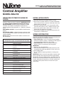
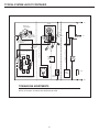
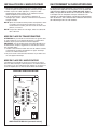
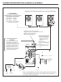
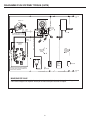
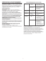
INSTALLATION & OPERATING INSTRUCTIONS
READ & SAVE THESE INSTRUCTIONS!
Central Amplifier
MODEL IMA-516
INTERCOM SYSTEM FOR HOME OR
OFFICE
A typical system will include inside intercom speakers and door
speaker(s) if door answering is required. A MAXIMUM OF TEN
(10) INSIDE REMOTE SPEAKER STATIONS AND TWO (2)
DOOR SPEAKERS. Intercom speakers designed for outside
installation are available. The Amplifier has provisions for
connecting optional input equipment; i.e.: radio/music, electronic
chime.
RADIO/MUSIC SOURCE – A separate NuTone Radio-Intercom
System.
ELECTRONIC CHIME – A NuTone Electronic or Musical Chime
may be connected to the amplifier to provide chime tones in the
intercom speakers.
NOTE: Models IA-28 or IA-29 chime modules cannot be used
with the IMA-516.
SPEAKER REFERENCE CHART
(Use applicable rough-in and specified wire with all models)
MODEL NUMBER
DESCRIPTION
Inside Intercom Speakers
ISB-53 series
Speaker with controls. Recess mounts with Model
IR-3 Rough-In or may be surface-mounted with
Model IA-15.
IS-75
5" Paging Speaker - Roto-groove. Recess mounts with
Model IR-75 Rough-In.
IS-76
8" Paging Speaker - round. Recess mounts with Model
IR-70 Rough-In.
ISA-78 Series
8" Paging Speaker - rectangular. Recess mounts with
Model IR-80 Rough-In.
IC-501
Regulates volume in Inside Paging Speakers IS-75,
IS-76 or ISA-78.
Outside Intercom Speakers
ISB-53LW
Speaker with controls - surface mounted.
ISA-77
8" Paging Speaker - surface-mounted.
IS-79
8" Paging Speaker - recessed. Recess mounts with
Model IR-9 Rough-In.
Door Speakers
IS-67 series
Door Speaker with lighted pushbutton - molded.
Recess mounts with IR-6 Rough-In.
IS-69 series
Door Speaker with lighted pushbutton - Classic Cast
Metal. Recess mounts with IR-6 Rough-In.
ISA-63
Door Speaker - no pushbutton.
Molded - surface-mounted.
ISB-64
Door Speaker with unlighted pushbutton.
Molded - surface-mounted.
IA-70
Surface-mounting frame for recessed door speakers.
INSTALLATION DON'TS
1. Don't locate inside speaker stations on indoor exterior walls.
2. Don't place more than one speaker station in a room.
3. Don't locate two speaker stations in a common wall between
rooms; rooms that share a common wall should not have the
speaker stations on that wall.
4. Don't place a speaker station so it is facing another station,
even if the other station is across a hallway in another room.
5. Don't locate speaker stations where doors or furniture will
interfere with the operation of the speaker.
6. Don't locate the amplifier in an area where temperatures will
exceed 120°F or fall below 32°F.
WIRING INFORMATION
CAUTION: This system is designed to be used with NuTone
wire/cable. No other wire should be used. use of wire other than
NuTone specified will cause improper operation.
* NuTone Model IW-6 – Use for connection between Amplifier
and intercom speakers. IW-6 is a 3-twisted-pair cable (3 pairs of
22 gauge wire with variable twists; color-coded).
* NuTone Model IW-2 – Use for connections specified in
diagrams. IW-2 is one twisted-pair cable (22 gauge).
IMPORTANT
1. Observe local code requirements.
2. Route all system wiring as far as possible (at least 12") from
household power wiring, lamp dimmers, furnace controls, etc.
3. Avoid stapling cables.
4. Be sure amplifier is properly grounded to an earth ground
source.
IMPORTANT: NuTone cannot be responsible for improper radiointercom operation that results from interference generated by
light dimmers, fluorescent lighting fixtures, and similar electrical
products. Such interference must be corrected at the source. As
an aid to help reduce this interference, all remote speaker wires
and cables must be placed at least 12 inches from any A.C.
power wiring.
INSTALLING THE AMPLIFIER
CONNECTION TO RADIO-INTERCOM
1. Determine exact location for all components. Check plans
against the “Installation Don'ts.”
2. Run designated wire to component locations, including power
wiring to transformer and low-voltage wiring between
transformer and amplifier.
3. Make wire connections and mount components. Note that
some components (especially speakers) may require a rough-in
frame.
NOTE: After the first two speaker stations are wired, supply
power to the system and test for proper operation. Wire and
test the remaining speaker stations one at a time.
NOTE: If UL listed wire is required, use IW-6-UL and IW-2-UL.
This is the primary application. By connecting a non-intercom
IMA-516 speaker system to a NuTone Radio-Intercom System
(2000, 3000, 3300, 4000 or 5000 model series), radio/music can
be provided to selected locations where intercom is not needed.
Example: A doctor's office may need radio-intercom in the office
areas and radio/music only in the waiting-reception area.
MOUNTING THE TRANSFORMER
CAUTION: Do not install the transformer in attic, crawl space, or
on lighting fixture. High ambient temperature will cause
transformer to cut out.
IMPORTANT: If replacing an IM-516 with IMA-516, replace
transformer with Model 301-T transformer
1. In keeping with local electrical code, mount 301-T transformer
in one of the following locations: fuse box, circuit breaker box,
or utility box in an accessible area.
2. Do not cover transformer with insulation. Do not use
transformer for other appliances.
MOUNTING THE AMPLIFIER
The amplifier is surface-mounted to a finished wall, or mounted on
a single-gang outlet box. It must be located in an area that is
accessible for making adjustments and for servicing if required.
Two mounting holes are provided in the amplifier base plate.
MOUNTING
HOLES
DECREASE
DECREASE
INCREASE
INTERCOM
VOLUME
CONTROL
INPUT
ORN /WHT
INPUT
ORN
CHIME
CHIME
OUTPUT
HI
RED
INCREASE
RADIO
VOLUME
CONTROL
DOOR
BLK
DOOR
BLK /WHT
AC
AC
OUTPUT
LO
RED WHT
IMA-516 AMPLIFIER (WITH COVER REMOVED)
2
INTERCOM SYSTEM FOR HOME OR OFFICE
MAXIMUM OF 10 REMOTE SPEAKER STATIONS AND 2 DOOR SPEAKERS
ISB-53
ISB-53
ISB-53
SPEAKER/WIRE
SPECIFICATIONS
MAXIMUM OF 3 SPEAKERS MAY BE CONNECTED ON
SAME WIRE RUN. MAXIMUM CABLE LENGTHS.
1 SPEAKER
500 FEET
2 SPEAKERS
250 FEET
3 SPEAKERS
150 FEET
BLK
BLK / WHT
DO NOT EXCEED 4000 FEET OF IW-6 PER SYSTEM
ORN
ORN/ WHT
RED
RED / W
SPECIFICATIONS FOR LOW-LEVEL OUTPUT CONNECTION.
(1) Minimum 5mv for 50mv output (least useable output).
(2) 50mv for 4 watts (full output).
(3) Maximum input voltage: 1 volt.
(4) Input impedence: 100K ohms.
PROCEDURE FOR THIS
CONNECTION:
(1) Turn Radio Volume Control on
IMA-516 Amplifier to minimum
NUTONE IW-2
(extreme counterclockwise
position)
(2) Make wire connections.
(3) Supply power and adjust the
LOW-LEVEL
INPUT WIRES
radio/music volume at the source.
BLUE & BLACK
(4) Finally, increase IMA-516 Radio
Volume Control to desired level.
LOW-LEVEL RADIO/MUSIC OUTPUT
(1) NuTone Radio-Intercom 2000, 3000,
3300, 4000 or 5000 model series. Lowlevel music output provided - black and
blue wires connect with IW-2 (max.
10 ft.) to black and blue input wires on
IMA-516 Amplifier.
(2) Speaker connected to an existing AM/FM
radio music source. Use IW-2 (max. 10
ft.) to connect the IMA-516 low-level
input leads to the speaker terminals.
DECREASE
DECREASE
INCREASE
INTERCOM VOLUME
CONTROL
INPUT
ORN /WHT
INCREASE
RADIO VOLUME
CONTROL
DOOR
BLK
DOOR
BLK /WHT
INPUT
ORN
14 GAUGE
NUTONE IW-2 (MAX. 200 FT)
120vAC, 60Hz HOUSE POWER
OBSERVE LOCAL CODE
NUTONE
ELECTRONIC CHIME
SEE CHIME
INSTALLATION
INSTRUCTIONS
18/2
(NUTONE
S-143)
AC
CHIME
AC
OUTPUT
LO
RED WHT
OUTPUT
HI
RED
IMA-516
CENTRAL AMPLIFIER
NUTONE IW-2
(MAX 400 FT)
FIELD
GROUNDING
WIRE
DOOR SPEAKER MAY
BE CONNECTED TO
BLACK AND BLACK
WHITE TERMINALS
IN AMPLIFIER OR
REMOTE SPEAKER
DOOR
SPEAKER
18 / 2 (NUTONE S-143 150 FT MAX.)
18/2
(NUTONE
S-143)
TO PUSH
BUTTON(S)
CHIME
DOOR SPEAKER
MODELS WITH
CHIME PUSHBUTTON.
RUN 18 /1 (S-143)
TO CHIME LOCATION
MODEL 301T
TRANSFORMER
TO CHIME
TRANSFORMER
NOTE: If desired NuTone Model: ISB-53W (outdoor speaker) may be used.
The ISB-53W has the same features as the ISB-53 except that it is weather-resistant.
3
MUSIC-ONLY SPEAKER SYSTEM
A separate radio/music source may be connected to a nonintercom IMA-516 speaker system to provide a music-only
system.
SPECIFICATIONS FOR LOWLEVEL OUTPUT CONNECTION
(1) Minimum 5mv for 50mw output
(least useable output).
(2) 50 mv for 4 watts (full output).
(3) Maximum input voltage: 1 volt.
(4) Input impedence: 100k ohms.
Procedure for this connection:
(1) Turn Radio Volume Control on
IMA-516 Amplifier to minimum
(extreme counterclockwise
position).
(2) Make wire connections.
(3) Supply power and adjust the
radio-music volume at the
source.
(4) Finally, increase IMA-516
Radio Volume Control to
desired level.
LOW-LEVEL RADIO/MUSIC OUTPUT
(1) NuTone Radio-Intercom. Low-level music output
provided - black and blue wires; connect with IW-2
(max. 10 ft.) to black and blue input wires on IMA-516
Amplifier.
(2) Existing stereo receiver with tape output jacks. Make
connection from black and blue low-level input wires
on IMA-516 Amplifier - to - tape output jacks (use “y”
adaptor to make connection to both channel A and B
jacks). Use IW-2 (max. 10 ft.).
(3) Speaker connected to an existing AM/FM radio music
source. use IW-2 (max. 10 ft.) to connect the
IMA-516 low-level input leads to the speaker
terminals.
NUTONE IW-2
LOW-LEVEL
INPUT WIRES
BLUE & BLACK
MODEL 301T
TRANSFORMER
IMA-516
DECREASE
DECREASE
INCREASE
INCREASE
INTERCOM VOLUME
CONTROL
120vAC,
60Hz HOUSE
POWER
OBSERVE
LOCAL CODE
18 / 2 (NUTONE S-143)
INPUT
ORN /WHT
INPUT
ORN
MODELS IS-75,
IS-76, ISA-77
ISA-78, IS-79
CHIME
CHIME
OUTPUT
HI
RED
IC-501 (OBSOLETE)
VOLUME CONTROL
RADIO VOLUME
CONTROL
DOOR
BLK
DOOR
BLK /WHT
AC
AC
OUTPUT
LO
RED WHT
NUTONE IW-2 (MAX. 500 FT. TO 2 SPKR.)
(MAX 250 FT TO 4 SPKR.)
(MAX 125 FT. TO 8 SPKR.)
4
FIELD
GROUNDING
WIRE
TYPICAL SYSTEM LAYOUT
The IMA-516 system can be used for two types of apartment layouts: (1) low-rise garden apartments that have a single entrance,
(2) townhouse apartments that have separate entrances for each apartment.
(For systems using 481-B or N482-BX speakers with buzzers)
TO 3RD FLOOR
APARTMENTS
TO 3RD FLOOR
APARTMENTS
TRANSFORMER WIRE
481B OR
N482-BX
APARTMENT
SPEAKER
DOOR RELEASE
WIRE
BUZZER WIRE
IW-6
TO APT. SPEAKER
1ST FLOOR
2ND FLOOR
BLK/W
BLACK
ORANGE
ORANGE
RED/W
18 GA. SINGLE CONDUCTOR OR MULTI-CONDUCTOR CABLE
481-B or 482-BX
APARTMENT
SPEAKER
18 GA.
BUZZER
WIRE
RED
TO
TRANSFORMER
TO
DOOR
RELEASE
NUTONE IW-6, 4000 FT. MAX. PER SYSTEM.
500 FT. MAX. ANY ONE RUN
1ST FLOOR
DECREASE
IMA-516
CENTRAL
AMPLIFIER
DECREASE
INCREASE
INTERCOM
VOLUME
CONTROL
INCREASE
RADIO
VOLUME
CONTROL
INPUT
ORN/WHT
NUTONE IW-2
(400 FT. MAX.)
DOOR BLK
DOOR
BLK / WHT
INPUT
ORN
AC
1
AC
2
CHIME
OUTPUT
HI RED
3
OUTPUT
LO
RED WHT
18 GA.
18 GA.
CHIME
MAIN ENTRANCE
DIRECTORY MODEL 498
OR INDIVIDUAL DOOR
SPEAKERS WITH
PUSHBUTTONS
18/2
(NUTONE S-143)
OBSERVE
LOCAL CODE
MODEL 301T
TRANSFORMER
14 GA.
120vAC,
60Hz HOUSE
POWER
2500 FT. MAX. TO
LAST SPEAKER BUZZER
FIELD
GROUNDING
WIRE
DR-1 DOOR
RELEASE
(OPTIONAL) POSTAL LOCK
SWITCH (MODEL 499).
DOTTED LINE WIRING
(18GA.) 2000 FT.
MAX. BETWEEN DOOR RELEASE
AND LAST SPEAKER
LOW-RISE GARDEN APARTMENTS
A typical system includes an entrance directory (with pushbuttons and speaker), apartment
speakers (with built-in door buzzer or a separate door chime), and an electric door release.
5
TYPICAL SYSTEM LAYOUT CONTINUED
18 GA
TO APT.
NO. 3
N482BX
N482BX
MODEL 301T
TRANSFORMER
BLK
ORN
120vAC, 60Hz
HOUSE POWER.
OBSERVE LOCAL
CODE.
AC
FIELD
GROUNDING
WIRE
CHIME
OPTIONAL
DOOR
RELEASE
DOOR SPEAKER
AC
RED
OPTIONAL
DOOR
RELEASE
18 GA
14 GA
NUTONE IW-2 (100 FT. MAX.)
BLK / WHT
18 GA
CHIME
ORN
BLK
TO APT.
NO. 1
NUTONE IW-2 (100 FT. MAX.)
IMA-516
CENTRAL AMPLIFIER
IW-6
RED
18/2
(NUTONE
S-143)
BLK
PAIR
NOT
USED
IW-6
ORN/W
NUTONE IW-6 MAX. 4000 FT.
PER SYSTEM. MAX. 500 FT.
ANY ONE RUN
ORN / WHT
TO APT.
NO. 3
RED/W
BLK/W
DOOR
SPEAKER
RED / WHT
PUSH
BUTTON
PUSH
BUTTON
18 GA 2000 FT. MAX. TO LAST DOOR RELEASE.
2500 FT. MAX. TO LAST SPEAKER BUZZER
APARTMENT NO. 1
APARTMENT NO. 2
TOWNHOUSE APARTMENTS
A typical system includes individual door speakers and apartment speakers with built-in door
buzzer. As an option, an electric door release may be used.
6
TO APT
NO. 3
INSTALLER'S TROUBLESHOOTING GUIDE
OPERATIONAL CHECKOUT
INTERCOM SYSTEM FOR HOME OR OFFICE VOLUME
SETTING – Each remote speaker's volume control should be set
between 3/4 and full volume. The intercom Volume Control in the
Amplifier should be set about 1/3 of its rotation. In general, keep
the remote speaker's volume control high and the amplifier
intercom volume control relatively low.
MODEL ISB-53 SPEAKER –
INTERCOM – Press the INTERCOM button to speak with inside
or patio speakers. To speak with the door speaker, lock in the
DOOR button and press INTERCOM button. To listen, release the
intercom button.
MONITORING – To monitor a specific speaker location, lock in
the TALK LOCK button. The speaker will now transmit sounds to
other speakers. NOTE: Be certain the speaker set for
monitoring has its volume control set to maximum level.
DOOR ANSWERING INTERCOM FOR APARTMENTS
To talk, place the intercom switch to TALK. To listen, place the
button to LISTEN. To activate the door release, press the DOOR
button to OPEN.
MUSIC-ONLY SPEAKER SYSTEM
The maximum volume for the radio/music is set at the source. The
amplifier has a Radio Volume control which can decrease the
volume which is set at the music source.
1. System does
not work.
1a.Improper wire.
1a.NuTone Model IW-6 cable
must be used with this
system. No other wire can
be used.
1b.Power supply.
1b.Check 120vAC, 60Hz
house power supply to
transformer
2. System worked 2. Improper
temporarily.
transformer.
3. No intercom.
3. Intercom gain
control.
4. No radio/music 4a.Radio volume
(optional).
control.
4b.Short in wiring.
2. NuTone Model 301T
transformer must be used.
3. Check setting of intercom
gain control.
4a.Be certain volume control
on radio/music source is
set sufficiently high. Next
check radio volume control
on amplifier.
4a.Be certain volume control
on radio/music source is
set sufficiently high. Next
check radio volume control
on amplifier.
TROUBLESHOOTING HINT: If system does not work, remove
remote speaker and accessory wiring from amplifier, then connect
a pair of test speakers. Connect one test speaker to the orange
pair terminals and connect the other test speaker to the red pair
terminals. If sound is heard, the amplifier is operational. Begin
connecting one remote speaker at a time and testing for proper
operation. If remote speaker does not work, check for wiring error
(improper connection or short).
7
Two Year Limited Warranty
WARRANTY OWNER: NuTone warrants to the original consumer purchaser of its products that such products will be free from defects in materials or workmanship for a period
of two (2) years from the date of original purchase. THERE ARE NO OTHER WARRANTIES, EXPRESS OR IMPLIED, INCLUDING, BUT NOT LIMITED TO, IMPLIED
WARRANTIES OF MERCHANTABILITY OR FITNESS FOR A PARTICULAR PURPOSE.
During this two year period, NuTone will, at its option, repair or replace, without charge, any product or part which is found to be defective under normal use and service.
THIS WARRANTY DOES NOT EXTEND TO FLUORESCENT LAMP STARTERS OR TUBES, FILTERS, DUCT, ROOF CAPS, WALL CAPS AND OTHER ACCESSORIES
FOR DUCTING. This warranty does not cover (a) normal maintenance and service or (b) any products or parts which have been subject to misuse, negligence, accident,
improper maintenance or repair (other than by NuTone), faulty installation or installation contrary to recommended installation instructions.
The duration of any implied warranty is limited to the one year period as specified for the express warranty. Some states do not allow limitation on how long an implied warranty
lasts, so the above limitation may not apply to you.
NUTONE’S OBLIGATION TO REPAIR OR REPLACE, AT NUTONE’S OPTION, SHALL BE THE PURCHASER’S SOLE AND EXCLUSIVE REMEDY UNDER THIS
WARRANTY. NUTONE SHALL NOT BE LIABLE FOR INCIDENTAL, CONSEQUENTIAL OR SPECIAL DAMAGES ARISING OUT OF OR IN CONNECTION WITH
PRODUCT USE OR PERFORMANCE. Some states do not allow the exclusion or limitation of incidental or consequential damages, so the above limitation or exclusion may
not apply to you. This warranty gives you specific legal rights, and you may also have other rights, which vary from state to state. This warranty supersedes all prior warranties.
WARRANTY SERVICE: To qualify for warranty service, you must (a) notify NuTone at the address stated below or telephone 1/800-543-8687, (b) give the model
number and part identification and (c) describe the nature of any defect in the product or part. At the time of requesting warranty service, you must present
evidence of the original purchase date.
Date of Installation
Builder or Installer
Model No. and Product Description
IF YOU NEED ASSISTANCE OR SERVICE:
For the location of your nearest NuTone Independent Authorized Service Center:
Residents of the contiguous United States Dial Free 1-800-543-8687
Please be prepared to provide:
Product model number • Date and Proof of purchase • The nature of the difficulty
Residents of Alaska or Hawaii should write to: NuTone Inc. Attn: Department of National Field Service, 4820 Red Bank Road, Cincinnati Ohio 45227-1599.
Residents of Canada should write to: Broan-NuTone Canada, 1140 Tristar Drive, Mississauga, Ontario, Canada L5T 1H9.
Rev. 03/2001
Product specifications subject to change without notice.
4820 Red Bank Road, Cincinnati, Ohio 45227
Printed in Taiwan, Rev. 4/01, Part No. 48163
DIRECTIVES D’INSTALLATION
LIRE ET CONSERVER CES DIRECTIVES
Amplificateur Central
MODÈLE IMA-516
SYSTÈME D’INTERPHONE POUR LE
MAISON OU LE BUREAU
CHOSES À NE PAS FAIRE LORS DE
L'INSTALLATION
Ce type de système comprend des haut-parleurs pour
l’interphone et un ou des haut-parleurs de porte. UTILISER UN
MAXIMUM DE DIX (10) HAUT-PARLEURS INTERIEURS
DISTANTS ET DE DEUX (2) HAUT-PARLEURS DE PORTE.
Des haut-parleurs d’interphone pour l’extérieur sont également
offerts. Différents appareils optionnels peuvent en outre être
raccordés à l’amplificateur, notamment: source radio/musicale,
carillon électronique.
SOURCE RADIO/MUSICALE – Système radio-interphone
NuTone distinct.
CARILLON ELECTRONIQUE – Carillon électronique ou
musical NuTone raccordé à l’amplificateur pour assurer la
diffusion des tonalités du carillon dans les haut-parleurs de
l’interphone.
NOTE: Les modèles de carillon IA-28 et IA-29 ne peuvent pas
être raccordés au IMA-516.
1. Ne pas placer les haut-parleurs intérieurs sur des murs
extérieurs.
2. Ne pas placer plus d'un haut-parleur dans une pièce
3. Ne pas placer plus d'un haut-parleur sur le mur séparant deux
TABLEAU DE RÉFÉRENCE–HAUT-PARLEUR
(Utiliser bôitiers et fils recommandés pour chaque modèle)
NUMÉRO DE MODÉLE
DESCRIPTION
Haut-parleurs intérieurs pour interphone
Série ISB-53
Haut-parleur avec commandes. Installation encastrée
avec bôitier IR-3 ou affleurante avec boîtier IA-15.
IS-75
Haut-parleurs de recherche de personnes de 5 po, rond
et concave. Installation encastrée avec bôitier IR-75.
IS-76
Haut-parleur de recherche de personnes de 8 po, rond.
Installation affleurante avec boIitier IR-70.
Série ISA-78
Haut-parleur de recherche de personnes de 8 po, rond.
Installation affleurante avec boIitier IR-80.
IC-501
Commande du volume pour haut-parleurs intérieurs de
recherche de personnes IS-75, IS-76 ou ISA-78.
Haut-parleurs extérieurs pour interphone
ISB-53LW
Haut-parleur avec commandes, installation en surface.
ISA-77
Haut-parleur de recherche de personnes de 8 po,
installation en surface.
IS-79
Haut-parleur de recherche de personnes de 8 po.
Installation affleurante avec bôitier IR-9.
Haut-parleurs d’entrée
Série IS-67
Haut-parleur d’entrée avec bouton-poussoir moulé
illuminé. Installation affleurante avec bôitier IR-9.
SérieIS-69
Haut-parleur d’entrée avec bouton-poussoir illuminé;
cadre métallique classique. Installation affleurante avec
bôitier IR-6.
ISA-63
Haut-parleur d’entrée sans bouton-poussoir, moulé.
Installation en surface.
ISB-64
Haut-parleur d’entrée avec bouton-poussoir moulé, non
illuminé. Installation en surface.
IA-70
Cadre installé en surface pour haut-parleur d’entrée
affleurant.
pièces. Les haut-parleurs ne doivent pas êntre installés sur le
mur mitoyen séparant deux pièces.
4. Ne pas placer un aut-parleur de façon qu'il soit face à un
autre haut-parleur, même si ce dernier est situé, par exemple,
dans une piéce donnant sur l'entrée.
5. Ne pas placer les haut-parleurs derriére une porte ou là ou
sera placé un meuble.
6. Ne pas installer l'amplificateur à un endroit où la la
température sera supérieure à 120ºF ou inférieurer à 23ºF.
CÂBLAGE
ATTENTION: Ce système est conçu pour être utilisé avec des
fils et câbles NuTone. Aucun autre type de fil ne doit être utilisé.
Le fait d'utiliser d'autres fils que les fils NuTone pourrait nuire au
fonctionnement de l'appareil.
* NuTone Modèle IW-6 – Sert à raccorder l'amplifacteur et les
huat-parleurs de l'interphone. Le IW-6 est un câble à trois
paires torsadées (trois paires de fils calibre 22, torasadées,
avec code de couleur).
* NuTone Modèle IW-2 – Sert aux connexions indiquees dans
les illustrations. Le IW-2 est un câble à une paire torasadées,
constituée de fils calibre 22.
IMPORTANT
1. Respecter les codes du bâitment en vigueur.
2. Faire passer tous les fils du système le plus loins possible (au
moins à 12 po) des câbles d'alimentation, des rhéostats des
thermostats, etc.
3. S'assurer que l'amplificateur est bein mis à la terre.
IMPORTANT
NuTone n'est pas responsable du mauvais fonctionnement du
radio-interphone attribuable à des interférence produites par les
rhéostats, les dipositifs d'éclairage flourescent et les autres
appareils électriques similaries. De tels interférences doivent
être éliminés à la source. Pour réduire au minimum les risque
d'intereférence, les câbles des haut-parleurs distants doivant
être situés à au moins 12 po de tout câble d'alimentation c.a.
INSTALLATION DE L'AMPLIFICATEUR
RACCORDEMENT AU RADIO-INTERPHONE
1. Déterminer d'abord l'emplacement prévu chaque élément.
Vérifier les plans en tenant compte des "Choses à ne pas faire".
2. Mettre en place les câble appropries, y compris le câble
d'alimentation du transformateur et cle cIable basse tension
reliant l'amplificateur au transformateur.
3. Faire les branchements, puis installer les éléments. À
remarquer que certains éléments, notamment les haut-parleurs,
extigent un bôitier.
NOTE: Après avoir installé les deux premiers haut-parleurs, mettre
le systéme sous tension et procéder à des essais de
fonctionnement. Installer, puis faire l'essai des autres haut
parleurs, un à la fois.
NOTE: Lorsque des câbles UL sont exigés, utiliser les câbles IW6UL et IW-2-UL.
Il s'agit de la principale application. En branchant un systéme
de haut-parleurs IMA-516 sans interphone à une système de
radio-interphone NuTone (modèles 2000,3000,3300, 4000,ou
5000), il est possible de diffuser des un stsèeme de radioou de
la musique là où un interphone n'est pas nécessaire. Par
exemple: un cabinet de médicin a besoin d'un radio-interphne
dans les bureaux, mais seulement d'une diffusion d'emissions
de radio/musique dans la salle d'attente.
MISE EN PLACE DU TRANSFORMATEUR
ATTENTION: Ne pas installer les transformateur au grenier, dans
un vide sanitaire ni sur un appareil d'eclairage. La temperature
ambiante élevée pourant entraîner l'arrét de l'appareil.
IMPORTANT: Lors du remplacement d'un modèle IM-516 par un
modèle IM-516, remplacer également le transformateur existant
par un modéle 301-T.
1. Installer le transformateur 310-T dans l'un des endroits suivants,
conformément aux codes du bâitement en vigeur: électrique
situeè à un endroit facile d'accès.
2. Ne pas recouvrir le transformateur d'isolant; ne pas utliser avec
un autre appareil électrique.
MISE EN PLACE DE L'AMPLIFICATEUR
L'amplificateur est installé en surface sur un mur fini ou encore
dans une bôite électrique. Il doit être placé à un endoit facilement
accessibe au cas où il faudrait faire des réglages ou le réparer. Le
socle de l'amplificateur est muni de deux orifices d'installation.
ORIFICES D'INSTALLATION
DIMINUER
DIMINUER
AUGMENTER
VOLUME DE
L'INTERPHONE
ENTRÉE
ORANGE/BLANC
ENTRÉE
ORANGE
CARILLON
CARILLON
SORTIE
HTROUGE
AUGMENTER
VOLUME
DE LA
RADIO
PORTE
NOIR
PORTE
NOIR/BLANC
AC
AC
SORTIE
BTROUGE/BLANC
AMPLIFICATUR IMA-516 (couvercle enlevé)
2
SYSTÈME D'INTERPHONE POUR LE MAISON OU LE BUREAU
MAXIMUM DE 10 HAUT-PARLEURS DISTANTS ET DE 2 HAUT-PARLEURS DE PORTE
CARACTÉRISTIQUES
DES HAUT-PARLEURS/CÂBLES
UN MAXIMUM DE TROIS HAUT-PARLEURS PEUVENT
ÊTRE RACCORDÉS À L'AIDE D'UN MÊME FIL.
LONGUEUR MAXIMUM DES CÂBLES.
1 HAUT-PARLEUR
500 PIEDS
2 HAUT-PARLEUR
250 PIEDS
3 HAUT-PARLEUR
150 PIEDS
ISB-53
ISB-53
ISB-53
NE PAS UTILISER PLUS DE 4,000 PIEDS
NOIR
NOIR/BLANC
DE CÂBLE IW-6 PAR SYSTÈME.
ORN
ORN/BLANC
ROUGE
ROUGE/BLANC
CONNEXION À LA SORTIE BASSE-TENSION
(1) Minimum 5mV pour une sortie de 50mV (minimum utilsable).
(2) 50mV pour 4 watts (sortie maximum).
(3) Tension d'entrée maximum: 1 Volt.
(4) Impédence d'entrée: 100 Kohms.
SORTIE BASS-TENSION POUR LA
RADIO/MUSIQUE
(1) Radio-interphone NuTone, modéles de
séries 2000, 3000, 3300, 4000 or 5000
Sortie basse tension pour musique brancher les fils noir et bleu avec le câble
IW-2 (maiximum 10 pieds) aux fils noir et
bleu d'entrée de l'amplificateur IMA-516.
(2) Haut-parleur raccordé à une source
radio/musique existante. Utiler du câble
IW-2 (maximum 10 pieds) pour brancher
les fils d'entrée basse tension du IMA516 aux bornes du haut-parleur.
PROCÉDURE DE CONNEXION:
(1) Placer la commande du volume
de la radio sur l'amplificateur
IMA-516 au minimum (tourner
complètement dans le sens
antihoraire).
(2) Connecter les fils.
(3) Mettre sous tension, puis régler
le volume de la radio/musique à
la source.
(4) Enfin, augmenter la volume de
la radio du IM-516 au niveau
désiré.
NUTONE IW-2
FILS D'ENTRÉE
BASSE TENSION
BLEU ET NOIR
DIMINUER
DIMINUER
AUGMENTER
VOLUME DE
L'INTERPHONE
AUGMENTER
VOLUME DE
LA RADIO
ENTRÉE
ORN/BLANC
PORTE
NOIR
PORTE
NOIR/BLANC
ENTRÉE
ORN
CALIBRE 14
CARILLON
AC
NUTONE IW-2
(MAXIMUM 400 PIEDS)
CARILLON
AC
ALIMENTATION DOMESTIQUE
60 Hz, 120 V; RESPECTER LES
CODES EN VIGEUR
TRANSFORMATEUR 301-T
CARILLON
ÉLECTRONIQUE
NUTONE-VOIR LES
DIRECTIVES
D'INSTALLATION DU
CARILLON
VERS LE
BOUTONPOUSSOIR
FIL DE MISE
À LA TERRE
LE HAUT-PARLEUR DE PorTE
PEUT ÊTRE RACCORDER
AUX BORNES NOIRE OU
NOIRES ET BLANCHES DE
L'AMPLIFICATEUR OU À UN
HAUT-PARLEUR DISTANT
HAUT-PARLEUR DE PORTE
AMPLIFICATEUR CENTRAL
IMA-516
HAUT-PARLEUR
DE PORTE
18 / 2 (NUTONE S-143 150 PIEDS MAXIMUM)
18/2
(NUTONE
S-143)
18/2
NUTONE
S-143)
SORTIE
BTROUGE/BLANC
SORTIE
HTROUGE
NUTONE IW-2 (MAX. 200 PIEDS)
VERS LE
TRANSFORMATEUR
DU CARILLON
HAUT-PARLEUR DE PORTE AVEC
BOUTON-POUOIR DE CARILLON.
INSTALLER DU FIL 16/1 (S-143)
JUSQU'AU CARILLON
TRANSFORMATUER
MODEL 301T
NOTE: Le modèle ISB-53W (haut-parleur extérieur) NuTone peut être utilisé si désiré.
Le modèle ISB-53W possède les mêmes caractéristiques que le modèle ISB-53,
mais il résiste en plus aux intempéries.
3
SYSTÈME DE HAUT-PARLEURS POUR MUSIQUE SEULEMENT
Une radio/source musicale distinct peut être raccordèe au système de haut-parleurs sans interphone
IMa-516 pour la diffusion de musique seulement.
CARACTÉRISTIQUES DES
CONNEXIONS À L'ENTRÉE BASSE
TENSION
(1) Minimum de 5mV pour une sortie
de 50mV (minimum utilisable)
(2) 50 mV pour 4 watts (sortie
maximum).
(3) Tension d'entrée maximum: 1 volt.
(4) Impedence d'entrée: 100 Kohms.
Procédure de connexion:
(1) Placer la commande du volume de
la radio sur l'amplificateur IMA--516
au minimum (tourner comlètement
dans le sens antihoraire).
(2) Connecter les fils.
(3) Mettre sous tension, puis régler le
volume de la radio/musique à la
source.
(4) Enfin, augmenter le volume de la
radio du IMA-516 au niveau désiré.
SORTIE BASSE TENSION POUR RADIO/MUSIQUE
(1) Radio-interphone NuTone. Sortie basse tension pour
musique-brancher les fils noir et bleu avec le câble
IW-2 (maximum 10 pieds) aux fils noir et bleu
d'entrée de l'ampficateur ima-516.
(2) Récepteur stéréo existant avec sorties pour lecture
de bande. Placer un câble entre les fils noir et bleu
de l'amplficateur IMA-516 et sorties du lecteur de
bande (utiliser un adaptateur en "Y" pour les voies A
et B). Utiliser du câble IW-2 (maximum 10 pieds).
(3) Haut-parleur raccordé à une radio MA-MF/source
musicale existante. Utiliser du câble IW-2 (maximum
10 pieds) pour brancher les fils d'entrée basse
tension du IMA-516 aux bornes du haut-parleur.
NUTONE IW-2
FILS D'ENTRÉE
BASSE TENSION
BLEU ET NOIR
TRANSFORMATEUR
MODÉLE 301-T
IMA-516
DIMINUER
DIMINUER
AUGMENTER
AUGMENTER
VOLUME DE
L'INTERPHONE
ALIMENTATION
DOMESTIQUE
60Hz,120 V;
RESPECTER LES
CODES EN VIGEUR
ENTRÉE
ORN/BLANC
18 / 2 (NUTONE S-143)
ENTRÉE
ORN
MODÉLES
IS-75,
IS-76, ISA-77
CARILLON
CARILLON
SORTIE
HTROUGE
COMMANDE DU
VOLUME IC-501
(DÉSUÈTE)
VOLUME DE LA
RADIO
PORTE
NOIR
PORTE
NOIR/BLANC
AC
AC
SORTIE
BTROUGE/BLANC
FIL DE MISE
À LA TERRE
NUTONE IW-2 (MAX. 500 PIEDS POUR 2 HAUT-PARLEURS)
(MAX 250 PIEDS POUR 4 HAUT-PARLEURS)
(MAX 125 PIEDS POUR 8 HAUT-PARLEURS)
4
DIAGRAMME D'UN SYSTÈME TYPIQUE
Les systèmes IMA-561 peuvent être installés dans deux types d'édifice: (1) les édifices à appartements comprenant une seule entrée; (2)
les maisons de ville dont chaque appartetment possède une entrée individuelle.
(POUR SYSTÈMES AVEC HAUT-PARLEURS 481-B OU N482-BX AVEC SONNETTE)
VERS LES
APPARTEMENTS
DU 3e ÉTAGE
VERS LES
APPARTEMENTS
DU 3e ÉTAGE
FIL DU TRANSFORMATEUR
HAUTPARLEUR
481B OU
N482-BX
FIL DU DISPOSITIF
D'OUVERTURE DE
LA PORTE
FIL DE LA SONNETTE
IW-6
VERSE LE HAUT-PARLEUR
DEL'APPARTEMENT DU 1er ÉTAGE
2e ÉTAGE
HAUT-PARLEUR
481B OU N482-BX
BLK/W
CÂBLE CALIBRE 18, MONO OU MULTICONDUCTEUR
VERS
LES
TRANSFORMATEUR
18 GA.
BLACK
ORANGE
ORN/W
FIL DE LA
SONNET
RED
RED/W
TO
DOOR
RELEASE
CÂBLE NUTONE IW-6, 4000 PIEDS MAX.
PAR SYSTÈME. 500 PIEDS MAX.
SANS RACCORDEMENTS
1e ÉTAGE
DIMINUER
DIMINUER
AUGMENTER
VOLUME DE
L'INTERPHONE
AMPLIFICATEUR
CENTRAL
IMA-516
AUGMENTER
ENTRÉE
OR/BL
INPUT
ORN
NUTONE IW-2
(400 PIEDS MAX.)
VOLUME DE
LA RADIO
DOOR BLK
PORTE
NOIR
AC
1
CARILLON
AC
2
SORTIE
HT- ROUGE
SORTIE
BTROUGE/BLANC
18 GA.
18 GA.
CARILLON
RÉPERTOIRE CENTRAL,
MODÈLE 498,OU HAUTPARLEUR DE PORTE
INDIVIDUEL AVEC
BOUTON POUSSOIR
18/2
(NUTONE S-143)
RESPECTER
LES CODES
EN VIGEUR
3
TRANSFORMATEUR
MODÉLE 301-T
14 GA.
ALIMENTATION
DOMESTIQUE
6060 Hz 120 V
2500 PIEDS MAX.
JUSQ"UA DERNIER
HAUT-PARLEUR AVEC
SONNETTE
FIELD
GROUNDING
WIRE
DR-1 DOOR
RELEASE
(OPTIONNEL)
COMMUNICATEUR POUR
SERURE DE BÔITE
POSTALE (MOD`ELE 499)
FIL EN POINTELLÉ
2000 PIEDS
MAX.(CALIBRE 18) ENTRE
DISPOSITIF D'OUVERTURE DE LA
PORTE ET LE DERNIER HAUTPARLEUR
ÈDIFICE À APPARTEMENTS
Le système typique comprend un répertoire central (avec boutons-poussoirs et haut-parleur),
des haut-parleurs d'appartement (avec sonnette intégré ou carillon de porte distinct) et un
dispositif électrique d'ouverture de porte.
5
DIAGRAMME D'UN SYSTÈME TYPIQUE (SUITE)
18 GA
N482BX
VERS LE
APPARTEMENT
DU 3e
N482BX
TRANSFORMATEUR
MODÉLE 301T
NOIR
ORN
AIMENTATION
DOMESTIQUE
NOIR/BLANC
60 Hz , 120 V; RESPECTER
ORN/BLN
LES CODES EN VIGUEUR
CARILLON
NOIR/BLN
14 GA
IW-6
DISPOSITIF
D'OUVERTURE DE
PORTE
OPTIONNEL
AC
FILS DE LA
MISE À LA
TERRE
HAUT-PARLEUR DE PORTE
AC
HAUTPARLEUR
DE
PORTE
ROUGE ROUGE/BLANC
2,000 PIEDS (CALIBRE 18) JUSQU'AU DERNIER
DISPOSITIF D'OUVERTURE DE LA PORTE
2,500 PIEDS MAX JUSQU'AU DERNIER HAUTPARLEUR AVEC SONNETTE
DISPOSITIF
D'OUVERTURE
DE PORTE
OPTIONNEL
18 GA
CARILLON
ORN
18 GA
NOIR
PAIRE
NON
UTILISÉE
TO APT.
NO. 1
NUTONE IW-2 (100 FT. MAX.)
AMPLIFICATEUR
CENTRAL
IMA-516
NUTONE IW-2 (100 PIEDS MAX.)
18/2
(NUTONE
S-143)
NOIR
IW-6
ROUGE
NUTONE IW-6 MAX. 4000 PIEDS
PER SYSTEM. MAX. 500 PIEDS
ORN /BLN
ROUGE/BLN
BOUTONPOUSSOIR
BOUTONPOUSSOIR
LE APPARTEMENT DU 1e
LE APPARTEMENT DU 2e
VERS LE
APPARTEMENT
DU 3e
MAISONS DE VILLE
Le système typique comprend des haut-parleurs de porte individuels et des haut-parleurs d'appartement
avec sonnet intégrée. Un dispositif électrique d'ouverture de porte est offert en option.
6
GUIDE DE DÉPANNAGE DE L'INSTALLATEUR
VÉRIFICATION DU FONCTIONNEMENT
RÉGLAGE DU VOLUME DU SYSTÉME D'INTERPHONE POUR
LE FOYER OU LE BUREAU– Le volume du chaque haut-parleur
doit être ouvert au moins aux 3/4. La commande du volume de
l'amplificateur doit être réglée à environ au 1/3. Règlé générale, il
faut garder le volume des haut-parleurs élevé, et celui de
l'amplificateur plutôt bas.
HAUT-PARLEUR ISB-53 –
INTERPHONE – Appuyer sur le bouton INTERCOM pour
communiquer avec les haut-parleurs intérieurs ou du jardin. Pour
communiquer avec le haut-parleur de porte, appuyer
simultanément sur les boutons DOOR et INTERCOM. Pour
entendre la personne à la porte, relâcher le bouiton INTERCOM.
SUVEILLANCE– Pour surveiller un endroit donné, appuyez sur
TALK LOCK.Ce haut-parleur émettra alors à destination de tous
les autres haut-parleurs du système. NOTE: Assurez-vous que
la commande du volume du haut-parleur placé en mode
SURVEILLANCE est réglée au maximum.
INTERPHONE AVEC DISPOSITF D'OUVERTURE DE PORTE
POUR APPARTEMENTS Pour parler, placer le commutateur de l'interphone à TALK. Pour
entendre la personne à la porte, placer le commutateur à LISTEN.
Pour déclencher l'ou verture de la porte, placer le commutateur
DOOR à OPEN.
SYSTÈME DE HAUT-PARLEURS POUR DIFFUSION DE
MUSIQUE SEULEMENT
Le volume de la radio/musique est réglé à la source.
L'amplificateur est muni d'une commande qui permet de diminuer
le volume de la sourc musicale.
1. Le système ne 1a.Câblage non
fonctionne pas.
approprié.
1b.Alimentation
2. Le système a
2. Transformateur
temporairement
non approprié.
fonctionné.
1a.Il faut utiliser du câble
NuTone IW-6 avec ce
système. Aucun autre type
de câble n'est approprié.
1b.Vérifier l'alimentation
120V, 60 Hz du
transformateur.
2. Il faut utiliser un
transformateur NuTone
301-T.
3. Aucun
interphone
3. Commande du
gain de
l'interphone
3. Vérifier le réglage de la
commande du gain de
l'interphone.
4. Aucune
radio/musique
(optionnel
4a.Commande du
volume de la
radio.
4a.S'assurer que le volume
de la source musical/radio
est suffisamment élevé.
Vérifier ensuite la
commande du volume de
la radio de l'amplicateur.
4b.Court-circuit
4b.S'assurer que le volume
de la source
musicale/radio est
suffisamment élevé.
Vérifier ensuite la
commande du volume de
la radio de 'amplificateur.
TRUCS DE DÉPANNAGE: Si le système ne fonctionne pas,
débrancher les haut-parleurs et les accessoires de
l'amplificateur, puis brancher un ensemble de haut-parleurs
d'essai. Brancher un haut-parleur aux bornes oranges et l'autre
aux bornes rouges. Si les haut-parleurs fonctionnent,
l'amplificateur est correct. Brancher alors les haut-parleurs
distants, un à la fois, pour en vérifier le fonctionnement. Si l'un
d'eux ne fonctionne pas, vérifier le câblage (connexion
incorrecte ou court-circuit).
7
Garantie limitée de deux ans
GARANTIE DU PROPRIÉTAIRE: NuTone garantie à l'acheteur original de ses produits que ces derniers seront exempts de tout défaut de matériaux et de fabrication pour une période
de deux (2) ans à compter de la date d'achat. AUCUNE AUTRE GARANTIE, IMPLICITE OU EXPRESSE, N'EST DONNÉE, Y COMPRIS, MAIS SANS S'Y LIMITER, GARANTIE DE
MARCHANDIBILITÉ OU D'ADAPTATION À UN USAGE PARTICULIER.
Pendant cette période de deux ans, NuTone procédera au remplacement ou à la réparation sans aucuns frais, mais à sa propre discrétion, de tout produit ou pièce jugé défectueux
dans le cadre d'une utilisation normale. CETTE GARANTIE NE VISE PAS LES DISPOSITIFS D'AMORÇAGE NI LES TUBES DES LUMINAIRES FLUORESCENTS. Cette garantie ne
couvre pas (a) l'entretien et le service courants ni (b) les produits et les pièces ayant fait l'objet d'un usage abusif, de négligence, d'un accident, d'un entretien ou d'une réparation non
appropriée (par du personnel non autorisé par NuTone), d'une mauvaise installation ou d'une installation non conforme aux directives d'installation fournies.
La durée de toute garantie implicite est limitée à la période de deux ans précisée pour la garantie expresse. Certains états ne reconnaissent pas les restrictions relatives à la durée des
garanties implicites; il se pourrait donc que cette restriction ne s'applique pas dans votre cas.
LE REMPLACEMENT OU LA RÉPARATION PAR NUTONE, À SA PROPRE DISCRÉTION, DE TOUT PRODUIT OU PIÈCE DÉFECTUEUX CONSTITUE LE SEUL REMÈDE DE
L'ACHETEUR EN VERTU DE CETTE GARANTIE. NUTONE NE PEUT ÊTRE TENUE RESPONSABLE DES DOMMAGES INDIRECTS, CONSÉCUTIFS OU SPÉCIAUX
ATTRIBUABLES À L'UTILISATION OU AU RENDEMENT DU PRODUIT. Certains états ne reconnaissent pas les restrictions ni les exclusions relatives aux dommages indirects,
consécutifs ou spéciaux; il se pourrait donc que cette restriction ne s'applique pas dans votre cas. La présente garantie vous accorde des droits spécifiques, mais vous pourriez aussi
avoir d'autres droits en fonction de l'état dans lequel vous résidez. Cette garantie remplace toute autre garantie donnée précédemment.
SERVICE SOUS GARANTIE Pour être admissible au service sous garantie, vous devez (a) aviser NuTone, à l'adresse fournie ci-dessous ou par téléphone au 1 800 5433687, (b) fournir le numéro du modèle et la description de la pièce et (c) décrire la nature du défaut de la pièce ou du produit. Au moment de la demande de service sous
garantie, vous devez fournir une preuve de la date d'achat originale.
Date d’installation
Entrepreneur ou installateur
N° de modèle et description du produit
POUR OBTENIR DE L’ASSISTANCE OU DU SERVICE:
Pour connaître le Centre de service NuTone autorisé indépendant le plus proche:
Résidents des États-Unis continentaux, composez le numéro sans frais: 1 800 543 8687
Garder à protée de la main le numéro du modèle, la date et la preuve d’achat, le type de problème.
Résidents de l’Alaska et d’Hawaii: Écrivez à NuTone Inc. Attn: Department of National Field Service, 4820 Red Bank Road, Cincinnati Ohio USA 45227-1599.
Résidents du Canada: Écrivez à Broan-NuTone Canada, 1140 Tristar Drive, Mississauga, Ontario Canada L5T 1H9.
Rev. 03/2001
Les caractéristiques peuvent être modifiées sans préavis
4820 Red Bank Road, Cincinnati, Ohio 45227
Imprimé aux É.-U., Rev. 4/01, Piéce n° 48163


![Roberts Gorden Combat UHD[X][S][R] 75 Service manual](http://vs1.manualzilla.com/store/data/007422233_1-2ad797071a19a12c5337ec2864a74fd9-150x150.png)