1
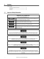
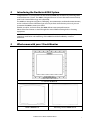
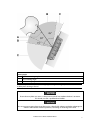
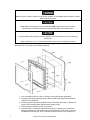
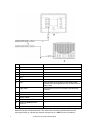
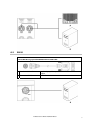
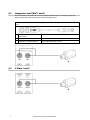
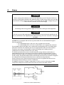
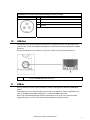
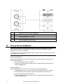
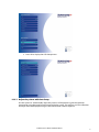
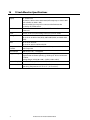
Northstar 8000i 15" Monitor Installation Manual www.northstarnav.com 1 Preface In this chapter Important Safety Information........................................ 2 Disclaimer ............................................................................. 4 Warranty................................................................................ 4 1.1 Important Safety Information IMPORTANT SAFETY INFORMATION Please read carefully before use This is the safety alert symbol. It is used to alert you to potential personal injury hazards. Obey all safety measures that follow this symbol to avoid possible injury or death. WARNING indicates a potentially hazardous situation which, if not avoided, could result in death or serious injury. CAUTION indicates a potentially hazardous situation which, if not avoided, may result in minor or moderate injury. CAUTION used without the safety alert symbol indicates a potentially hazardous situation which, if not avoided, may result in property damage. It is your sole responsibility to use the Northstar 8000i in a manner that will not cause accidents, personal injury or property damage. Always observe safe boating practices. When navigating the vessel, use the Northstar 8000i only as a navigational aid. Proper navigation of the vessel is the sole responsibility of the vessel operator. Depth soundings should be used only for navigation. Never use a depth sounding to gauge depth, range or other conditions for swimming or diving. The Global Positioning System (GPS) is operated by the US Government which is solely responsible for its operation, accuracy, and maintenance. The GPS system is subject to changes which could affect the accuracy and performance of all GPS equipment anywhere in the world. 2 Northstar 8000i 15" Monitor Installation Manual The electronic chart used by the Northstar 8000i is an aid to navigation designed to supplement, not replace, official government charts. Only official government charts supplemented by notices to mariners contain the information required for safe and prudent navigation. Always supplement the electronic information provided by the Northstar 8000i with other plotting sources such as observations, depth soundings, radar and hand compass bearings. Should the information not agree, the discrepancy must be resolved before proceeding any further. Never operate the 8000i in Simulate Mode while you're underway. It is the user's responsibility to ensure that Simulate Mode is used only in safe situations such as when you are moored in a marina. The accuracy of the sonar depth display can be limited by many factors, including the type of transducer, the location of the transducer, and water conditions. Ensure that the transducer is installed and used correctly. The radar must be set up before it is used for the first time. See "Set up the radar before using it" in the Radar Installation manual. Never look directly into the scanner at close range while the radar is operating. Radar scanners emit electromagnetic energy at a frequency that can be harmful at close range. Always keep the recommended safe distance from the scanner as follows: Scanner Model Vertical beam angle of scanner (degrees) Minimum safe distance (100 Watts per m² average power density) Note 1 Minimum safe distance (10 Watts per m² average power density) Note 2 2 kW 30 1.6 ft (0.5 m) 4.6 ft (1.4 m) 4 kW 25 3 ft (0.9 m) 9.3 ft (2.8 m) 6 kW 20 3.6 ft (1.1 m) 11.5 ft (3.5 m) 10 kW 20 9.5 ft (2.9 m) 30 ft (9.0 m) 25 kW 20 18 ft (5.5 m) 57 ft (17.4 m) NOTES: Limits apply to exposure within the vertical beam angle. Note 1: Peak occupational exposure limit pursuant to IEC 60936 Clause 3.27 and IEC 62252 Clause 4.32 Note 2: General public exposure limit pursuant to IEC 60936 Clause 3.27 and IEC 62252 Clause 4.32 Northstar 8000i 15" Monitor Installation Manual 3 Failure to adhere to these warnings may lead to death, serious injury or property damage. Northstar disclaims all liability for installation or use of this product that causes or contributes to death, injury or property damage or that violates any law. You are strongly recommended to scan all removable media (such as USB memory sticks or CDs) for viruses or corrupt data on a separate device BEFORE connecting or using the removable media with the 8000i. 1.2 Disclaimer As Northstar is continuously improving this product we retain the right to make changes to the product at any time which may not be reflected in this version of the manual. Please contact your nearest Northstar distributor if you require any further assistance. It is the owner’s sole responsibility to install and use the instrument and transducers in a manner that will not cause accidents, personal injury or property damage. The user of this product is solely responsible for observing safe boating practices. BRUNSWICK NEW TECHNOLOGIES INC. AND ITS SUBSIDIARIES AND AFFILIATES DISCLAIM ALL LIABILITY FOR ANY USE OF THIS PRODUCT IN A WAY THAT MAY CAUSE ACCIDENTS, DAMAGE OR THAT MAY VIOLATE THE LAW. Governing Language: This statement, any instruction manuals, user guides and other information relating to the product (Documentation) may be translated to, or has been translated from, another language (Translation). In the event of any conflict between any Translation of the Documentation, the English language version of the Documentation will be the official version of the Documentation. This manual represents the product as at the time of printing. Brunswick New Technologies Inc. and its subsidiaries and affiliates reserve the right to make changes to specifications without notice. Copyright © 2006 Brunswick New Technologies Inc. Northstar™ is a registered trademark of Brunswick New Technologies Inc. 1.3 Warranty The Northstar Warranty Statement is supplied as a separate document. It is shipped with the Product Registration Card. In case of any queries, refer to www.northstarnav.com. 4 Northstar 8000i 15" Monitor Installation Manual Contents 1 Preface 2 1.1 1.2 1.3 Important Safety Information....................................................................................... 2 Disclaimer............................................................................................................................. 4 Warranty ............................................................................................................................... 4 2 Introducing the Northstar 8000i System 7 3 What comes with your 15 inch Monitor 7 4 The Northstar 8000i 15 inch Monitor 9 4.1 4.2 Front view and keys.......................................................................................................... 9 Back view and connectors ...........................................................................................11 5 Mounting the Northstar 8000i 15 Inch Monitor 12 6 Utility 15 7 External Wake Up and Remote Power On 15 8 Video Types and Connectors 18 8.1 8.2 8.3 8.4 RGB1 and RGB2 ................................................................................................................18 DVI-D ....................................................................................................................................19 Composite1 and 2 (BNC 1 and 2)...............................................................................20 S-Video 1 and 2.................................................................................................................20 9 Power 21 10 USB Out 23 11 USB In 23 12 Turn on the 15 inch Monitor 24 13 Turn off the 15 inch Monitor 25 6 14 The On Screen Display (OSD) 14.1 14.2 14.3 14.4 14.5 14.5.1 14.5.2 14.5.3 14.5.4 14.5.5 14.5.6 Display the OSD menus ................................................................................................25 Set the video input source...........................................................................................26 Set the brightness ...........................................................................................................27 Set the touch control .....................................................................................................27 Display the OSD Setup menu .....................................................................................28 Adjust the picture with Auto Setup .........................................................................29 Adjust the color................................................................................................................30 Reset to defaults ..............................................................................................................31 Adjust the contrast .........................................................................................................32 Adjust the panel brightness........................................................................................33 Display the system information.................................................................................34 15 Maintenance 15.1 Technical support, service and repairs....................................................................35 16 15 inch Monitor Specifications Northstar 8000i 15" Monitor Installation Manual 25 35 36 2 Introducing the Northstar 8000i System Congratulations on your purchase of the Northstar 8000i, the revolutionary new integrated marine electronics system. The 8000i is designed for ease of use in the marine environment, with Touch Screen technology and online help. The 8000i can integrate navigation, fishfinding, instrumentation, multimedia entertainment, and an onboard camera. Whatever type of boat you have and however you use it, you can customize the 8000i to meet your needs. Flexible, modular, and innovative, the 8000i delivers awesome performance. Please take a few minutes to read through this manual before cutting holes or locating equipment. NOTE: The 8000i has several requirements that must be met to ensure safe and proper operation. Installation and interfacing of the 8000i should be handled by a marine technician. 3 What comes with your 15 inch Monitor 15" Monitor NS004710 Bezel CS000656A-G Mounting Gasket GA000138A-G Northstar 8000i 15" Monitor Installation Manual 7 Sun Cover CV000075A-G Cleaning Cloth MS000619A-G Pack of Protective Caps for unused ports HR000100 Mounting Screws HR000090 Power Cable AS000453-G Utility Cable NS004801 8 Mounting Template LA000601A-G Warranty Registration Card This Manual MN000607C-G Northstar 8000i 15" Monitor Installation Manual 4 The Northstar 8000i 15 inch Monitor The 15" Monitor has a high bright sunlight viewable display. It has a built- in Infrared Touch Control when used with a 8000i Black Box Processor. (The communication for the touch screen is via USB to the processor.) The purpose of 15" Monitor is to display the 8000i software from a Northstar 8000i Black Box Processor (NS004730). The 15" Monitor may also be used to display video fro 3rd party components such as PCs, Cameras and DVD player. This manual describes how to install the 15" Monitor and must be read with Northstar 8000i Black Box Processor and System Installation Manual. 4.1 Front view and keys The keys on the front of the 15" Monitor are physical keys that you can depress. Use these to: • turn the 15" Monitor on or off • quickly show or change the current video input source • adjust the brightness • access the OSD (On Screen Display) options and to change any or all of the OSD settings for the 15" Monitor itself (explained later in this manual) Northstar 8000i 15" Monitor Installation Manual 9 10 Key Function when NOT in OSD mode Function in OSD mode A Power Press once to turn on. Hold down for three seconds to turn off. If correctly wired using the Remote Power On feature this key also controls the power status of the Northstar 8000i Black Box Processor B Up Arrow Press to step up through the other video input source options. C Down Arrow Press to show the current video input source in the top left corner of the screen. Press again to step down through the other video input source options. D MENU Press once to show the OSD options. Press to exit the OSD options. E OK Press to show the current video input source in the top left corner of the screen. Press to select or accept changes to the OSD options and exit the OSD options. F Left Arrow Press once to decrease the brightness one step or hold down to change it rapidly. Press once to change an OSD setting (such as contrast) one step or hold down to change the setting rapidly. G Right Arrow Press once to increase the brightness one step or hold down to change it rapidly. Press once to change an OSD setting (such as contrast) one step or hold down to change the setting rapidly. H Infrared Receiver Not yet implemented I Screen 1024 x 768 resolution touch screen (XGA) J Finger Guides To guide fingers to the onscreen controls when using the 8000i software. K Mounting Bezel Clip-on bezel. Press once to step up through the OSD options. Press once to step down through the OSD options. Northstar 8000i 15" Monitor Installation Manual 4.2 Back view and connectors A BNC1 Video input from a composite video source B BNC2 Video input from a composite video source C SVIDEO1 Video input from a S-Video source D SVIDEO2 Video input from a S-Video source E RGB1 Video connection between the 15" Monitor and an 8000i processor or third party RGB source F RGB2 Video connection between the 15" Monitor and an 8000i processor or third party RGB source G POWER Power source input from vessel H UTILITY Connect the utility cable to enable Remote Power On from a Black Box Processor I DVI-D Receive DVI video input from an external video source (such as a PC) J USB IN Attach a USB peripheral K USB IN Attach a USB peripheral L USB OUT USB to an 8000i processor or other PC M Mount holes Use M4 machine screws to mount the 15" Monitor N VESA® Mount holes Use M4 machine screws (not supplied) to mount the 15" Monitor on a flat panel TV bracket (this method is NOT recommended for external locations). Northstar 8000i 15" Monitor Installation Manual 11 5 Mounting the Northstar 8000i 15 Inch Monitor Choosing the best mounting location Choose the mounting locations carefully before you drill or cut. The display for the 8000i System should be mounted so that the operator can easily use the controls and clearly see the display screen. Be sure to leave a direct path for all of the cables. The display screen is high-contrast and anti-reflective, and is viewable in direct sunlight, but for best results, install the 8000i 15" Monitor out of direct sunlight. The chosen location should have minimal glare from windows or bright objects. NOTE: The LCD itself is the front panel. There is no plastic lens in front of the LCD. It has a special bonded anti-reflective and scratchproof film on the LCD front to assure no fogging and best contrast. DO NOT hit the lens with sharp or heavy objects, since expensive LCD damage may occur. The 8000i system is designed to allow full operation of the unit from a USB mouse or other pointing device. If the mounting location means that the unit is not easily within reach of the user in the helm chair you may wish to also install a 8000i Remote Keypad or third party USB Trackball to the helm chair. Leave sufficient clearance space behind the 8000i 15" Monitor to connect all relevant cables. Good ventilation is required behind the mounting panel. Poor ventilation may cause the 8000i 15" Monitor to overheat, which, in turn, will cause the unit not to run at optimum performance. For overall width and height requirements, please see specifications (see "15 inch Monitor Specifications" page 36) . The 8000i system requires the use of the touch screen or external mouse. If the unit is to be mounted outdoors and may experience conditions that would require the Touch Screen to be disabled (e.g. Hail, Snow) we recommend that a waterproof pointing device (e.g. 8000i Remote Keypad or Waterproof USB mouse) is connected to the system. NOTE: The touch screen will only work with Northstar 8000i processors Viewing Angle The viewing angle can influence the viewability of the 8000i 15" Monitor. The best angle is from the top to slightly below perpendicular. Lower than perpendicular and the screen image will fade slightly. See following diagram. 12 Northstar 8000i 15" Monitor Installation Manual Viewing angle A Optimum viewing angle B Good viewing angle C Poor viewing angle or obstructed view Note: Color palates influence the viewing angle. Change to sunlight palate for increased visibility wen viewing in Zone C Ensure that any holes cut are in a safe position and will not weaken the boat's structure. If in doubt, consult a qualified boat builder. Do not mount any part where it can be used as a hand hold, where it might be submerged or where it will interfere with the operation, launching or retrieving of the boat. Northstar 8000i 15" Monitor Installation Manual 13 Before you cut a hole in a panel, make sure that there are no hidden electrical wires or other parts behind the panel. When flush mounting, be sure to mount the 8000i component on a flat surface. Mounting on a curved surface can result in water leaks around the cutout. To prolong life of this product, use the supplied sun cover when not in use and during washdown. After washdown or use in a wet environment remove excess water from screen Read and follow the Location guidelines and the Wiring guidelines in the Northstar 8000i Black Box Processor and System Installation Manual. 1. Find a suitable location for the 15" Monitor using the location guidelines. 2. Tape the mounting template in place, then cut the mounting hole and drill the screw holes in the panel. 3. Hold the gasket in place on the back of the 15" Monitor. Hold the 15" Monitor in place in the mounting hole and fit the mounting screws. 4. Clip the bezel to the front of the 15" Monitor. 5. Wire the cables as detailed in the following sections, taking care to follow the Wiring guidelines. Form the cables into loops below the 15" Monitor so that any condensation will drip off. The 15" Monitor and all connectors are waterproof. 14 Northstar 8000i 15" Monitor Installation Manual 6. Turn on the 15" Monitor's power supply and the Northstar 8000i System. 7. Finally, set up the 8000i system as described in the Northstar 8000i Black Box Processor and System Installation Manual. 6 Utility The provided Utility cable is mainly for providing wake up power to the 8000i Black Box Processor. The cable can also be used for programing by Northstar service centers 7 Pin Color Signal 1 Purple Reserved. Do not connect 2 Pink Reserved. Do not connect 3 Yellow Reserved. Do not connect 4 Black Ground 5 Black/White Reserved. Do not connect 6 White Reserved. Do not connect 7 Orange No connection 8 Blue No connection 9 Dark Green No connection 10 Brown/White Reserved. Do not connect 11 Gray External wakeup (output) 12 Light Green Remote power on (input) External Wake Up and Remote Power On External Wake Up sends a signal to another device to initiate Power On. Connect External Wake to the Remote Power On of the other device. The External Wake Up feature of the 8000i provides the ability for an 8000i Device to control the power state of another 8000i device that it is attached to. For example when the power button is pressed on the Northstar 15" Monitor it sends a + Volts signal through its Utility Cable (External Wake Up) to the Black Box Processors Utility Cable (Remote Power On). The processor detects the voltage and powers on. When the monitor is turned off, the 8000i Black Box Processor detects zero volts and and after (four) 4 seconds powers down. NOTE: that the processor takes up to 30 Seconds to power down. This will not be visible on the 15" Monitor. Allow time for the processor to shut down before removing power to the system. Northstar 8000i 15" Monitor Installation Manual 15 A Yellow B Black / White C White D Black E Orange F Blue G Dark Green H Grey External Wake Up (Gray Wire) on the Utility Cable. Connect this to the Light Green wire on the Processor Utility Cable I Light Green Remote Power On wire connected to the Black Box Processor J Purple K Pink L Brown / White M Northstar 8000i 15" Monitor N Northstar 8000i Black Box Processor O NS004801 Utility Cable Remote power is a feature of the 12" Display Processor, Black Box Processor, 15" Monitor, Network Sounder and Network Radar. This means that connecting the Remote Power On wire (Light Green) to a device that outputs voltage such as a 8000i Processor, breaker or 16 Northstar 8000i 15" Monitor Installation Manual switch will start the Unit. The voltage required for remote power on needs to be greater than 5 V DC. For example: Connect the Remote Power On wires (Light Green) of the (M)12" Processor (Upper Helm), (N) 12" Lower Helm, (T) Black Box Processor, (S) Sounder and (R) Radar to the External Wake Up of the (P) 15" Monitor. When the monitor is turned on the rest of the system will also turn on. Northstar 8000i 15" Monitor Installation Manual 17 8 Video Types and Connectors The Northstar 15 " Monitor has the following video inputs. 8.1 Video Input Connect to Cable Required Remarks DVI PC DVI or compatible NS004805 Video from a computer DVI or equivalent RBB 1 8000i Processor NS004806 Supplied with the 8000i Black box processor RGB 2 RGB Video NS004807 For third party RGB (VGA) Video sources 1024 x 768 (BNC 1) Composite Video NS004803 Cable has 8000i screw type connector to a 75 Ω BNC (BNC 2) Composite Video NS004803 Cable has 8000i screw type connector to a 75 Ω BNC S-Video 1 S-Video NS004804 Cable has 8000i screw type connector to a female S-Video Connector S-Video 2 S-Video NS004804 Cable has 8000i screw type connector to a female S-Video Connector RGB1 and RGB2 Use the NS004806 cable to connect the 15" Monitor to the 8000i Processor (supplied with the 8000i Black Box Processor) From 18 To Resolution A 12" Display RGB Port Northstar 15" Monitor RGB 1 or 2 800 x 600 A Black Box Processor Northstar 15" Monitor RGB 1 or 2 1024 x 768 B Third Party PC or Northstar 15" Monitor processor RGB 1 or 2 1280 x 1024 Native resolution is 1024 x 768 but will scale from 640 x 480 to 1280 x 1024 Northstar 8000i 15" Monitor Installation Manual 8.2 DVI-D Connect DVI-D using optional NS004805 DVI-D to RGB cable Northstar 8000i 15" Monitor Any third party PC or processor that has DVI -D Video output A Connect to DVI-D DVI-D Connection Northstar 8000i 15" Monitor Installation Manual 19 8.3 Composite1 and 2 (BNC 1 and 2) The 15" Monitor can accept up to two (2) composite video inputs. To display composite video, change the video input in the onscreen display menu. Connect composite video sources using option NS004803 Composite video cable 6.5 ft (2 m) 8.4 20 Northstar 8000i 15" Monitor Connection Video Source A Northstar 15" Monitor BNC 1 Any Composite Video Source A Northstar 15" Monitor BNC 2 Any Composite Video Source S-Video 1 and 2 Northstar 8000i 15" Monitor Installation Manual 9 Power Before starting the installation, be sure to turn electrical power off. If power is left on or turned on during the installation, fire, electrical shock, or other serious injury may occur. Be sure that the voltage of the power supply is compatible with the 8000i’s voltage rating of 12 V DC or 24 V DC. (10 V DC - 35 V DC max range) Connecting to the wrong power supply can cause fire or damage to the equipment. Be sure to ground the equipment to prevent electrical shock and mutual interference. Be sure to use the fuse in the supplied power cable. Not using a fuse can cause fire or damage to the 8000i. All 8000i units are shipped with a 6 ft (2 m) power cable. This can be extended using the following guidelines for a cable length up to 15 ft (5 m), use 14-gauge wire or heavier for a cable length from 15 ft (5 m) to 30 ft (10 m), use 12-gauge wire or heavier If you lengthen the power cable, use an external fuse at the battery end as an added safety precaution. The fuse size should be chosen to be appropriate for the size of the smallest conductor in the circuit. See the NMEA or American Boating and Yachting Counsel specifications to find the correct fuse for your wiring. For the best protection from noise, connect the power wiring directly to the battery or dedicated electronics bus. The brown ground wire should be connected directly to ship’s ground. The power cable has an inline fuse on the positive and negative side to protect the vessel’s wiring, and prevent electrical fires and damage to the unit. If you shorten or lengthen this cable, be sure to keep the inline fuse intact (or provide circuit protection). Spare in-line fuses are standard automotive type and are not supplied with the unit and should be purchased locally to avoid loss of function. The 8000i can operate on voltages ranging from 10 V DC to 35 V DC. All Northstar 8000i components except the use the same 3 Pin power connector and cable as below. NOTE: Make sure the correct fuse is used Northstar 8000i 15" Monitor Installation Manual 21 Supplied NS004800 Power cable A Red Battery positive supply 12 V DC or 24 V DC B Black Battery negative supply C Green / Yellow Stripe (or Brown on older cables Ships ground (optionally connect to battery negative) D Fuse Fuse E Battery Battery 8000i System Power requirements Part No 22 Fuse or breaker Fuse or Max Power size @ 12 V breaker @24 V consumption Description NS004700 Northstar 8000i 12" Display Processor 10 Amp 5 Amp 50W NS004710 Northstar 8000i 15" Monitor 10 Amp 5 Amp 50 W NS004730 Northstar 8000i Black Box Processor 10 Amp 5 Amp 45 W NS004740 Northstar 8000i DVD-CD Player 5 Amp 3 Amp 7W NS004741 Northstar 8000i 1 kW Sounder 5 Amp 3 Amp 7.2 W NS004720 Northstar 8000i 4 Port USB Hub 5 Amp 3 Amp 14 W Northstar 8000i 2 kW Radar Scanner and Processor 10 Amp 5 Amp 25 W Northstar 8000i 4 kW Radar scanner and processor 10 Amp 5 Amp 30 W Northstar 8000i 6 kW Radar scanner and processor 10 Amp 5 Amp 120 W Northstar 8000i 10 kW Radar scanner and processor NA 7 Amp 250 W Northstar 8000i 25 kW Radar scanner and processor NA 7 Amp 180 W Northstar 8000i 15" Monitor Installation Manual NS8000i Processor Power Pinout (view looking at connector on unit) Pin Function 1 Battery - 2 Battery + 3 Ground Note: Drawing is the unit connector, not the cable 10 USB Out The unit has one Type B connector to connect to a system processor. This provides touch control of the screen and enables the USB ports on the monitor when connected to a 8000i processor. Position the Monitor no more than a (16.5 ft) 5 m cable run away from the processor. Northstar 8000i Black Box Processor 11 USB In The 15" Monitor has two Type A connectors, which are designed for Northstar 8000i USB Cables. Each USB port’s 5 V DC power output can provide up to 500 mA. Connect a USB Accessory, such as an 8000i System Remote Keypad, or a Northstar 8000i 4 Port Hub. NOTE: The recommended length for best performance is 2m (6 ft) The maximum cable length allowed is (16.5 ft) 5 m in between the peripheral and the processor. Northstar 8000i 15" Monitor Installation Manual 23 USB Dash mount connector (NS004709) Northstar 8000i Remote Key pad (NS004747) Northstar 8000i DVD / CD player C-Map Chart licence Key Northstar 8000i USB Video Capture 12 Turn on the 15 inch Monitor NOTE: The video input source connected at the rear of the 15" Monitor MUST match the video input source that's specified in the 15" Monitor OSD Menus. If it doesn't match, nothing is shown on the 15" Monitor. For example, if you've connected an RGB1 video source, the video input source must also be set to RGB1 in the OSD menus. Recommended Method: When the Black Box Processor and the 15" Monitor are wired using the remote power on wires of the utility cable 1. Press the Power key on the 15" Monitor. 2. The Northstar Marine Monitor (OSD) screen may appear briefly, followed by the Northstar 8000i screen. Alternative Method: When the Black Box Processor and the 15" Monitor are wired independently. 1. If the Black Box Processor is turned off, press the Power (ON/OFF) key at the rear. 2. The Power LED at the rear will glow red when the Black Box Processor is On. 3. Press the Power key on the 15" Monitor. 4. The Northstar Marine Monitor (OSD) screen may appear briefly, followed by the Northstar 8000i screen. 24 Northstar 8000i 15" Monitor Installation Manual 13 Turn off the 15 inch Monitor When the Black Box Processor and the 15" Monitor are both wired using the External wakeup and Remote power on wires of the utility cablet, hold down the Power key on the 15" Monitor for five seconds. This will force the processor to start shutting down If the Black Box Processor and the 15" Monitor are wired independently, hold down the Power key on the 15" Monitor for five seconds to turn it off. Hold down the Power (ON/OFF) key at the back of the Black Box Processor for five seconds. this will commence a system shut down. 14 The On Screen Display (OSD) Use the OSD menus to change all or any of the following settings for the 15" Monitor itself: Main Display Source DVI RGB1 RGB2 Composite1 Composite2 S-Video 1 S-Video 2 Brightness Setup menu (Auto Setup, Adjust Color, Reset to Defaults, Contrast, Panel Brightness, System Information) Touch NOTE: Without entering the OSD you have access to the following shortcuts press the up and down arrow keys to change the Main Display Source press the left and right arrow keys to change the Brightness. 14.1 Display the OSD menus 1. Press the MENU key to show the OSD Main Display Source menu and Display Functions menu. (The video input can be seen thought the transparent OSD) Northstar 8000i 15" Monitor Installation Manual 25 This symbol indicates that there are more options available in a sub-menu. 2. Use the keys on the front of the 15" Monitor to navigate around the OSD menus [also see (see "Front view and keys" page 9)] The left and right arrow keys operate only if a slider level bar is displayed or a sub-menu is available. When not accessing the OSD these buttons control the brightness levels Step up or down through the menu options. When not accessing the OSD these buttons select the video inputs Select an option and exit from the OSD menus Exit from the OSD 14.2 Set the video input source Select the video source by using the UP / DOWN arrows or use the OSD 1. Press the MENU key to show the OSD Main Display Source menu. (If you are displaying the Northstar 8000i system, this continues to be shown in the background in a dimmed state.) The current input source is shown with the TICK icon. 2. Use the up and down arrow keys to select the new input source that you want to use for the 15" Monitor. The selected item is highlighted. 3. Press OK to confirm the new input source 26 Northstar 8000i 15" Monitor Installation Manual 14.3 Set the brightness Use the LEFT / RIGHT buttons to alter the backlight brightness levels of the monitor or from with in the OSD 1. Press the MENU key to show the OSD main function menu. (If you are displaying the Northstar 8000i System, this continues to be shown in the background in a dimmed state.) 2. Use the up and down arrow keys to select the backlight rightness option. The selected item is highlighted and a slider bar appears on the screen to show the current setting. 3. Use the left and right arrow keys to change the brightness setting to the required level. (You can press a key to change the brightness by one step, or hold down a key to change the brightness more rapidly.) 4. Press the OK key to confirm the new brightness setting and to exit the OSD menus. 14.4 Set the touch control The Touch option is used to activate or de-activate the touch screen functionality of the 15" Monitor. The default factory state is for the Touch option to work ONLY when RGB1 is selected as the video source input. When the OSD menus are selected, the Touch option is automatically disabled but continues to show the TICK icon to indicate the status of the Touch option outside the OSD menus. If you want to clean the screen, you're recommended to turn off the 15" Monitor or to deactivate the Touch option. Northstar 8000i 15" Monitor Installation Manual 27 1. Press the MENU key to show the OSD Display Function Menu. (If you are displaying the Northstar 8000i system, this continues to be shown in the background in a dimmed state.) 2. Use the up and down arrow keys to select the Touch option. The selected item is highlighted. 3. An CROSS icon shows that the Touch Screen functionality is de-activated, a TICK icon shows that it is activated. 4. Press the OK key to change the setting. (Press OK again to toggle between the settings.) 5. When the Touch option is at the required setting, press the MENU key to confirm the new setting and to exit the OSD menus. 14.5 Display the OSD Setup menu 1. Press the MENU key to show the first level of OSD menus. (If you are displaying the Northstar 8000i System, this continues to be shown in the background in a dimmed state.) 2. Use the up and down keys to select the OSD Setup. The selected item is highlighted. 28 Northstar 8000i 15" Monitor Installation Manual 3. Press OK to display the OSD Setup menu. 14.5.1 Adjust the picture with Auto Setup Use this option to automatically adjust the position of the picture to give the optimum appearance using the input from the current display source. This will run a colour calibration and reposition the displayed image to the centre of the screen if required Northstar 8000i 15" Monitor Installation Manual 29 1. Display the OSD Setup menu. 2. The Auto Setup option is already highlighted. Press the OK key to start the autosetup adjustments. You may notice small horizontal and vertical adjustments of the picture while the auto-setup option is running. This takes only a few seconds. 3. When the picture has stabilized, the auto-setup is complete. 14.5.2 Adjust the color Use this option to select a preset color balance option or to customize your own color balance settings. The Original Panel Color is the recommended default setting. 1. Display the OSD Setup menu. 2. Use the up and down arrow keys to select Setup. 30 Northstar 8000i 15" Monitor Installation Manual 3. Use the up and down arrows to choose option. Press OK to select 3. Press the OK key to display the Adjust Color menu. 4. If you want to: select any of the preset color options, use the up and down arrows to select your choice then press the OK key to confirm your choice and exit the OSD menus. To define your own color balance, use the up and down arrows to select the User Preset option then press the OK key. The User Preset Option If you select the User Preset option, three slider bars appear on the screen to show the current settings for Red, Blue, and Green. 1. Use the up and down arrows to select the slider bar for the color that you want to change, then use the left and right arrow keys to change the color setting to the required level. (You can press a key to change the brightness by one step, or hold down a key to change the brightness more rapidly.) 2. Press the OK key to confirm the new color level and to return to the previous screen. 3. Re-select the User Preset option if you want to change another color. Otherwise, press the MENU key to exit the OSD menus. 14.5.3 Reset to defaults Use this option to return to the default settings for the 15" Monitor. Northstar 8000i 15" Monitor Installation Manual 31 1. Display the OSD Setup menu. 2. Use the up and down arrow keys to select the Reset to Defaults option. The selected item is highlighted. 3. Press the OK key to start the reset process. The screen may go black and/or the picture may re-adjust while the reset option is running. This takes only a few seconds. 4. When the screen has stabilized, the reset process is complete. 14.5.4 Adjust the contrast Use this option to adjust the contrast level of the 15" Monitor. The default setting is the optimum level. 1. Display the OSD Setup menu. 32 Northstar 8000i 15" Monitor Installation Manual 2. Use the up and down arrow keys to select the Contrast option. The selected item is highlighted and a slider bar appears on the screen to show the current setting. 3. Use the left and right arrow keys to change the contrast setting to the required level. (You can press a key to change the contrast by one step, or hold down a key to change the contrast more rapidly.) 4. Press the OK key to confirm the new contrast setting and to exit the OSD menus. 14.5.5 Adjust the panel brightness Use this option to adjust the panel brightness of the 15" Monitor. The default setting of 50% is the optimum level. 1. Display the OSD Setup menu. 2. Use the up and down arrow keys to select the Panel Brightness option. The selected item is highlighted and a slider bar appears on the screen to show the current setting. 3. Use the left and right arrow keys to change the panel brightness setting to the required level. (You can press a key to change the panel brightness by one step, or hold down a key to change the panel brightness more rapidly.) 4. Press the OK key to confirm the new panel brightness setting and to exit the OSD menus. Northstar 8000i 15" Monitor Installation Manual 33 14.5.6 Display the system information Use this option to show the system information for the 15" Monitor. 1. Display the OSD Setup menu. 2. Use the up and down arrow keys to select the System Information option. The selected item is highlighted and the system information is displayed on the right hand side of the screen. 3. Press the MENU key to exit the OSD menus when you are finished. 34 Northstar 8000i 15" Monitor Installation Manual 15 Maintenance Unless specified, clean the parts of the system with a damp cloth or mild detergent. Avoid abrasive cleaners, petrol or other solvents. Do not paint any part except for the cables or removable bezels. Cleaning a glass LCD display: Clean a glass display with the cloth supplied or with a lint free cloth a fluid for cleaning glass. Rub the display gently so as not to scratch it. Keep sensors and transducers free of weeds, paint and debris. Do not use a high pressure water jet on a paddle wheel speed sensor because it may damage the bearings. If you unplug a cable from a unit, fit the blanking caps supplied onto the connector on the unit. Do not expose any part of a plastic transducer to gasoline or paint solvents as they may weaken the plastic material. Wash only with water and detergent. Through hull and transom mount depth and speed transducers may be coated with a thin layer of antifouling paint. Only use water based antifouling paint. 15.1 Technical support, service and repairs Northstar products are manufactured and serviced by BNT Marine Electronics. The product is covered by a warranty which is supplied as a separate document. If you need technical support, or answers to other questions after you've followed the instructions in this manual, you can: • contact your Northstar distributor or • see the inside back cover of the manual or • visit www.northstarnav.com. Before you make contact, be sure to have: • the serial number of the hardware (usually shown on the faceplate of the unit). When you describe the problem, be as complete and as accurate as possible. Northstar 8000i 15" Monitor Installation Manual 35 16 15 inch Monitor Specifications Display 15" 24-bit color. Resolution: 1024 x 768 to 640 x 480 (will accept up to 1280 x 1024 and scale this to 1024 x 768). Direct bonded glass improves contrast and eliminates the possibility of condensation. Touch Screen Infrared touch screen controlled by USB from Northstar 8000i Processors Power 12 VDC or 24 V DC (max rating 10 V DC to 35 V DC 30 W) Analog RGB Up to 75 Hz or better at 1280 x 1024 (SXGA) Up to 85 Hz at 1024 x 768 (XGA), 800 x 600 (SVGA) and 640 x 480 (VGA) DVI-D Up to 75 Hz at SXGA Up to 85 Hz at XGA, SVGA and VGA Composite video NTSC, PAL/SECAM with input format of component video, S-video / S-Video and Composite. USB Interface USB 2.0 and 1.0, 1.1 compliant. Image Scaling Scale up/down a lower/higher resolution image to fit a higher/lower resolution panel, e.g. SVGA up to XGA or XGA down to SVGA. Scaling Range: VGA (640 x 480) ~ SXGA (1280 x 1024) Function Display On Screen Display (OSD) menu of functions. Environmental The case and cables are waterproof to IPx6. Operating Temperature 5ºF to 131ºF (-15ºC to 55ºC). 36 Northstar 8000i 15" Monitor Installation Manual UNITED STATES EUROPE 30 Sudbury Road, Unit 2, Ocean Quay, Acton, MA 01720, Belvidere Rd, Southampton, United States SO14 5QY, England Ph: +1 978.897.6600 Ph: +44 2380 339922 Fax: +1 978.897.7241 Fax: +44 2380 330345 [email protected] [email protected] AUSTRALIA NEW ZEALAND PO Box 479, PO Box 68 155, Gladesville, NSW 2111, Australia Newton, Auckland New Zealand Ph: +61 2 9879 9000 Ph: +64 9 481 0500 Fax: +61 2 9879 9001 Fax: +64 9 481 0590 [email protected] [email protected] www.northstarnav.com www.northstarnav.com Northstar 8000i 15" Monitor Installation Manual Made in New Zealand MN000607C-G