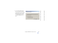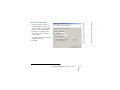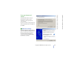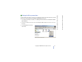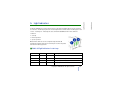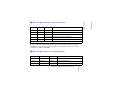
1
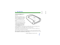
Electronic user’s guide released subject to "Nokia User’s Guides Terms and Conditions, 7th June, 1998"
Nokia 30 GSM Connectivity Terminal
User’s guide for modem use
9357346
Issue 2
DECLARATION OF CONFORMITY
We, NOKIA CORPORATION declare under our sole responsibility that the product TME-3 is in conformity with the provisions of the
following Council Directive: 1999/5/EC.
A copy of the Declaration of Conformity can be found from
http://www.nokia.com/phones/declaration_of_conformity/.
Copyright © 2002 Nokia. All rights reserved.
Reproduction, transfer, distribution or storage of part or all of the contents in this document in any form without the prior written
permission of Nokia is prohibited.
Nokia and Nokia Connecting People are registered trademarks of Nokia Corporation. Other product and company names mentioned
herein may be trademarks or tradenames of their respective owners.
HyperTerminal is a registered trademark of Hilgraeve Inc.
Nokia operates a policy of continuous development. Nokia reserves the right to make changes and improvements to any of the
products described in this document without prior notice.
Under no circumstances shall Nokia be responsible for any loss of data or income or any special, incidental, consequential or indirect
damages howsoever caused.
The contents of this document are provided "as is". Except as required by applicable law, no warranties of any kind, either express or
implied, including, but not limited to, the implied warranties of merchantability and fitness for a particular purpose, are made in
relation to the accuracy, reliability or contents of this document. Nokia reserves the right to revise this document or withdraw it at
any time without prior notice
The availability of particular accessories may vary by region. Please check with the Nokia dealer nearest to you.
FOR YOUR SAFETY 5
1. Introduction 6
Three ways of using the Nokia 30 with a compatible PC
or other compatible device: 7
Sales package 8
2. Features of the Nokia 30 9
Data connections and messaging 9
Supplementary services 11
AutoPIN 11
3. Getting started 12
Setting up the terminal 12
Installing the SIM card 13
Mounting the terminal 14
Placing the terminal 14
Terminal connectors 15
Entering the PIN code 17
Changing the PIN code 20
4. Modem installation for Nokia 30
terminal 21
Modem setup for Nokia 30 21
Introduction 21
Getting started 22
Modem Setup 22
Configure Nokia modem options 23
Create new Dial-up connection 24
GPRS connection 27
HSCSD or CSD connection 28
Enter user name and password 29
Name your connection 29
Set up your Internet mail account 30
Additional settings 30
Settings for Dial-up connections 31
Set properties 32
Connecting to the Internet 34
Uninstalling Modem setup for Nokia 30 36
Modem setup for standard modem driver 36
Communications software 37
5. Light indicators 39
6. Accessories 42
7. Troubleshooting 43
First things to check 43
Poor reception 43
Blocked PIN code 44
No connection 44
No Internet connection 45
Modem driver 45
Copyright ©2002 Nokia. All rights reserved.
3
Contents
Contents
Contents
9. Nokia 30 as an M2M Communications
device 48
IMPORTANT SAFETY INFORMATION 52
User control mode 48
AT command mode 49
M2M System mode 49
Placing the terminal for M2M communication 50
TECHNICAL SPECIFICATIONS 55
Copyright ©2002 Nokia. All rights reserved.
4
Contents
CARE AND MAINTENANCE 51
Contents
8. Access codes 46
Read these simple guidelines. Breaking the rules may be dangerous or illegal. Further detailed
information is given in this manual.
INTERFERENCE
All wireless devices may get interference, which could affect performance.
DO NOT USE IN HOSPITALS
Follow any regulations or rules. Do not use near medical equipment.
USE SENSIBLY
Do not touch the antenna unnecessarily.
QUALIFIED SERVICE
Only qualified personnel must install or repair equipment.
ACCESSORIES
Use only approved accessories. Do not connect incompatible products.
BACKUP COPIES
Remember to make backup copies of all important data.
CONNECTING TO OTHER DEVICES
When connecting to any other device, read its user’s guide for detailed safety instructions. Do not
connect incompatible products.
Copyright ©2002 Nokia. All rights reserved.
5
FOR YOUR SAFETY
FOR YOUR SAFETY
FOR YOUR SAFETY
The Nokia 30 is a GSM Connectivity
Terminal with many advanced
functions.
With the Nokia 30 GSM Connectivity
Terminal connected to your compatible
PC or to a compatible device, you can,
for example, make data calls, send
messages, connect to the Internet and
so on.
The Nokia 30 offers high speed wireless
connections and it supports several data
connection types such as GPRS, highspeed data, USSD and text messages
over EGSM900/GSM1800 networks.
The Nokia 30 GSM Connectivity Terminal also has highly useful security-related features such as
AutoPIN, GSM security codes and GSM encryption for end-user privacy.
The Nokia 30 has an internal antenna but if the signal strength is insufficient for optimal use, an
external antenna can be attached to the terminal.
When the Nokia 30 is attached to the data adapter RS-232, it can be used as a stand-alone modem
when connected to a compatible PC or compatible device. This user’s guide describes how to use of the
Nokia 30 GSM Connectivity Terminal as a wireless modem.
Copyright ©2002 Nokia. All rights reserved.
6
Introduction
Introduction
1. Introduction
Connected to a PC as a wireless modem
The Nokia 30 is connected to your computer and is installed on your computer as a modem.
Communications applications can subsequently be used to send and receive data over the wireless
connection provided by the Nokia 30. For more detailed information, see Modem installation for Nokia
30 terminal on page 21.
Connected to a PC and typing the AT commands on a terminal software
application
The AT commands are typed directly in an application, for example Hyper Terminal®. The Nokia 30,
used as a modem, follows these commands. See Entering the PIN code as an example of this on page
17.
Connected to an electronics application
When the Nokia 30 terminal is connected to the data adapter RS-232, it can be attached to a device
with a serial interface for a modem. This device communicates with the Nokia 30 via the RS-232
interface using integrated AT commands. Read more about the use of Nokia 30 for M2M
communications on page 49.
Copyright ©2002 Nokia. All rights reserved.
7
Introduction
Introduction
■ Three ways of using the Nokia 30 with a compatible PC or other
compatible device:
The complete sales package for the Nokia
30 GSM Connectivity Terminal includes
the following items:
1. Nokia 30 GSM Connectivity Terminal
2. Power supply ACW-5A
3. Data adapter RS-232
4. Data cable RS-232
5. Installation kit
6. Product note
7. Nokia 30 CD-ROM
Copyright ©2002 Nokia. All rights reserved.
8
Introduction
Introduction
■ Sales package
Note: Do not switch on the terminal when wireless device use is prohibited or when it may cause
interference or danger.
A number of features included in this guide are called Network Services. These are special services that
you arrange through your wireless service provider. Before you can take advantage of any of these
Network Services, you must subscribe to them through your service provider and obtain instructions for
their use from your service provider.
For example, features like wireless data connections and supplementary services are network
dependent features in Nokia 30 GSM Connectivity Terminal.
■ Data connections and messaging
The Nokia 30 GSM Connectivity Terminal supports five technologies for wireless data transfer, which
can be used where GSM networks support them. It is possible to use different AT commands depending
on the data bearer in use.
Note: Before you can use GPRS, HSCSD, CSD or USSD, you must subscribe to these services. You must
also save the settings for the applications used with these technologies. See Modem installation for
Nokia 30 terminal on page 21.
Copyright ©2002 Nokia. All rights reserved.
9
Features of the Nokia 30
In this chapter the main features of the Nokia 30 terminal are described in brief.
Features of the Nokia 30
2. Features of the Nokia 30
HSCSD
With HSCSD (High Speed Circuit Switched Data) the Nokia 30 acts as a multi-slot class 6 terminal and
it offers data transfer speeds of up to 43.2 kbit/s.
CSD
CSD (Circuit Switched Data) offers data speed of up to 14.4 kbit/s.
SMS
SMS (Short Message Service) is used to send and receive messages containing a maximum of 160
characters via the Nokia 30. SMS is a convenient way to pass data quickly and easily to and from Nokia
30 terminals.
USSD
USSD (Unstructured Supplementary Services Data) offers reliable interactive messaging services. USSD
can be used to send and receive messages containing a maximum of 182 characters via the Nokia 30.
With USSD, the session is established for the duration of the connection. This increases data transfer
reliability and shortens response times as the delay is known.
Note: USSD messages can only be sent to the network, not directly to another mobile terminal.
Copyright ©2002 Nokia. All rights reserved.
10
Features of the Nokia 30
With GPRS (General Packet Radio Service) data is transferred over the network in small, standardized
packets. Transferring data as packets makes the transfer more efficient. Given that the Nokia 30
supports GPRS multi-slot class 6, multiple timeslots can be used for data transfer at the same time.
Features of the Nokia 30
GPRS
• Call restriction to restrict outgoing and incoming calls.
• Call transfer to connect two different callers with each other and then disconnect one’s own call
without disturbing the other two callers.
• Call waiting alerts you of another incoming call during a phone call.
• In-call handling to switch between incoming and active calls.
• Multiparty call to connect several callers to one conversation.
• Security options such as Call barring.
You can take these supplementary services into use by changing the settings of Nokia 30. This can be
done using e.g. the Nokia 30 Configurator.
■ AutoPIN
SIM security in the Nokia 30 terminal can be achieved by using the AutoPIN feature that makes the
SIM card useless to any unauthorized user. The standard PIN request is used by default in the Nokia 30,
however, the AutoPIN feature can be switched on with the Nokia 30 Configurator software. The PIN
code is then programmed in the terminal’s memory where it is relayed in unusual situations, for
example when the terminal is restarted.
Copyright ©2002 Nokia. All rights reserved.
11
Features of the Nokia 30
The Nokia 30 terminal also supports additional network dependent services such as:
• Call forwarding to forward your calls to another number you specify.
Features of the Nokia 30
■ Supplementary services
■ Setting up the terminal
To use the Nokia 30 GSM Connectivity Terminal for the first time, proceed as follows:
1. Install the SIM card as described on page 13.
2. Mount the terminal on the data adapter RS-232.
3. Place the terminal in a proper location considering the field strength and antenna’s functionality.
4. Connect the data cable RS-232 to the terminal and to a compatible PC or other compatible device.
Connect the power supply ACW-5A to the terminal and to an AC wall outlet.
5. Enter the PIN code if your SIM card requires it.
Warning! To avoid damage to the SIM card, do not install, move or remove the SIM card if the power
supply is connected to an AC wall outlet. Mount the terminal on the data adapter RS-232 before
connecting the power supply.
Copyright ©2002 Nokia. All rights reserved.
12
Getting started
Getting started
3. Getting started
Keep all miniature SIM cards out of the reach of
small children.
The Nokia 30 SIM card reader supports 3V
small-size SIM cards.
The SIM card is attached in its position with
the plastic SIM cover. If you need to remove
the SIM card from the terminal, do so
carefully, for example using a sharp-pointed
tool.
Note: Removing the SIM card when the Nokia
30 is connected to the data adapter RS-232 is
not possible.
1. Remove the SIM cover from the terminal
by first lifting the wider end of the SIM
cover upwards.
2. Insert your SIM card into the slot and
make sure the golden contact area is
facing upwards and the bevelled corner is on the left.
3. Replace the SIM cover by pushing the narrow end in first, then snapping the cover closed.
Note: If the SIM card is installed but the Nokia 30 terminal still requires the insertion of a SIM card,
this means that your SIM card is not supported by the terminal. The Nokia 30 supports 3V SIM cards
only.
Copyright ©2002 Nokia. All rights reserved.
13
Getting started
Getting started
Installing the SIM card
Mount the terminal downwards on the data
adapter RS-232 and use the screws supplied
in the sales package to tighten the terminal in
the right position.
Note: If you wish to mount the terminal on a
wall, first attach the data adapter RS-232 to
the wall before mounting the terminal onto it.
Placing the terminal
Install the terminal either horizontally or vertically on the wall or on a horizontal surface. The best
installation location can be found with the help of the Intensity of Field strength (IoF) function
through the Nokia 30 light indicators (LEDs). See "Light indicators" on page 39.
If the internal antenna is not adequate, the use of additional external antenna is recommended.
For more detailed information on placing the terminal, refer to http:// www.forum.nokia.com if
needed.
Copyright ©2002 Nokia. All rights reserved.
14
Getting started
Getting started
Mounting the terminal
Terminal connectors
The Nokia 30 has four interfaces to connect to: M2M System, RS-232, power interface and external
antenna connector.
• M2M System connector
The M2M System connector is located at the bottom of the terminal.
When mounting the terminal the M2M system connector is attached to
the matching connector on the data adapter RS-232.
Copyright ©2002 Nokia. All rights reserved.
15
Getting started
Note: All radio transmitting devices send signals which may cause interference in different electronic
devices ( PC, television etc). To avoid interference, place the terminal far enough from other electronic
devices.
Getting started
Caution: In order to comply with RF exposure requirements, install the terminal so that a minimum
distance of 20 cm can be maintained between the antenna and all persons. If you use an external
antenna, install the antenna so that a minimum distance of 20 cm can be maintained between the
antenna and all persons, with antenna gain not exceeding 3 dBi.
1. Mount the Nokia 30 on the data adapter RS-232 first in order to
connect the terminal with a compatible PC or other compatible
devices.
2. Attach the data cable RS-232 to the adapter.
3. Connect the data cable from the terminal to a compatible PC or other
compatible device. Use only the data cable RS-232 supplied by Nokia.
• Power connector
The Nokia 30 power connector is at the back end of the terminal, opposite
the light indicators. When the Nokia 30 terminal is mounted on the RS232 adapter the power interface is found under the edge of the adapter.
- Connect the power cord from the power supply to the terminal.
- Connect the power supply to an AC wall outlet.
• External antenna connector
The external antenna connector is located next to the SIM card slot ( see picture on page 39). The
external antenna can be used with the external antenna cable (XRM-1) accessory if the signal strength
is insufficient.
- To connect the external antenna cable to the Nokia 30, cut off a piece of the SIM cover to fit the
cable in.
- Connect an external antenna with the FME connector to the other end of the external antenna cable.
Copyright ©2002 Nokia. All rights reserved.
16
Getting started
Getting started
• RS-232 connector
When the AutoPIN feature is switched on e.g. with the Nokia 30 Configurator software, the PIN code is
saved in the terminal’s memory and there is no need to type in the PIN code separately.
In a MS Windows environment, several applications can be used to establish the connection. One such
applications is HyperTerminal®. You can enter the PIN code with HyperTerminal as follows (in Windows
2000):
1. Start the HyperTerminal program (Start ->Programs ->Accessories ->Communications ->
HyperTerminal, then double-click the HyperTrm.exe icon).
2. In the Connection Description dialog box, type a
name for the connection in the Name box (for
example GSM1) and click OK.
Copyright ©2002 Nokia. All rights reserved.
17
Getting started
The PIN (Personal Identification Number) code protects your SIM card against unauthorised use. It is
usually supplied with the SIM card. If the SIM card requires a PIN code, you must enter this code to be
able to use the Nokia 30 terminal.
Getting started
Entering the PIN code
Copyright ©2002 Nokia. All rights reserved.
18
Getting started
Getting started
3. In the Connect To dialog box, there is a Connect
using list. In the list, select Direct to Com X, where
COM X is the COM port to which you have connected
the Nokia 30 terminal. Click OK.
5. In the HyperTerminal connection window, type
at and press ENTER. The program will answer
OK.
If you do not get an OK response, refer to the
section Troubleshooting on page 43.
Copyright ©2002 Nokia. All rights reserved.
19
Getting started
Getting started
4. In the COM X Properties dialog box, select the
port settings displayed in and click OK.
7. Press ENTER.
If the PIN code you enter fails three times in succession,
the code is blocked. Refer to the section Troubleshooting
on page 43.
Changing the PIN code
To protect your SIM card against unauthorised use, it is a
good idea to change the factory setting PIN code supplied by your service provider. Note that the PIN
code request must be set to on before you can change the PIN code with an AT command.
For example, to change the PIN code in the
HyperTerminal connection window:
1. Type in the following AT command
at+cpwd="sc","OLDPIN","NEWPIN"
where OLDPIN is the old PIN code and NEWPIN the
new code.
2. Press ENTER.
Note: The PIN code can also be changed using the
Nokia 30 Configurator software.
Copyright ©2002 Nokia. All rights reserved.
20
Getting started
Getting started
6. Type in the AT command at+cpin="PIN" where PIN is
your PIN code.
The Nokia 30 Modem Options run with Windows 98/Me/2000 or Windows NT 4.0 with Service Pack 5
or newer.
To connect to the Internet, to send and receive e-mail or faxes, or to transmit data from your PC, you
must have previously installed the appropriate data and fax communications software.
■ Modem setup for Nokia 30
Introduction
Modem Setup for Nokia 30 will install the following components on your computer:
• Nokia 30 data and fax modem adapters which enable you to use your phone as a modem in data
and fax calls
• Nokia Modem Options which enable you to set options for the data calls you make
Copyright ©2002 Nokia. All rights reserved.
21
Modem installation for Nokia 30 terminal
The Nokia 30 CD-ROM contains a Modem Setup which allows the Nokia 30 terminal to be used as a
wireless modem. The setup installs PC compatible data and fax modem drivers as well as Nokia Modem
Options which lets the user set parameters for data calls. Alternatively, you can use the standard
modem driver supplied with MS Windows. Either of these drivers allow the Nokia 30 terminal to be
used as a modem with most commercially available Internet browsers and e-mail applications
Modem installation for Nokia 30 terminal
4. Modem installation for Nokia 30 terminal
• close all the programs currently running in the PC
• make sure the PIN code request in the SIM card is disabled before inserting the SIM card into the
terminal. If the PIN code request is activated, the PIN code can be entered with an application such
as HyperTerminal.
• if you wish to activate the GPRS service, GPRS must be activated in the SIM card used with Nokia
30 terminal and your local Internet service provider must support GPRS service.
Modem Setup
The Nokia 30 modem driver is located on the CD-ROM or you can download the latest software from
www.forum.nokia.com.
1. Open the downloaded Modem Setup for Nokia 30 terminal exe files and save the files in a chosen
location.
2. Run the Set-up.
OR
1. From the CD-ROM main menu, click Install Software.
2. Click Install Modem Setup for Nokia 30.
3. Click Install and follow the instructions on the screen.
Be prepared to connect your phone to the PC, when prompted to do so.
Copyright ©2002 Nokia. All rights reserved.
22
Modem installation for Nokia 30 terminal
Before you install the ModemSetup for Nokia 30 terminal:
Modem installation for Nokia 30 terminal
Getting started
In order to use the Nokia 30 terminal as a wireless
modem, Nokia Modem Options must be configured for
your PC. These options define the modem to be used,
the connection type, GSM connection speed kbits/s and
the GPRS access point.
For example, to set the Installed Nokia modems using
MS Windows 2000:
1. In the Windows taskbar, press Start and select
Settings and Control Panel.
2. In the Control Panel, select Nokia Modem Options.
3. Select Nokia 30 (cable) from the Installed Nokia
Modems.
If you have a HSCSD connection from your service
provider, you can use connection speed up to 43.2
kbts/s.
If you have a CSD connection from your service
provider, you will be limited to a connection speed of 9.6 or 14.4 kbts/s.
If you have a GPRS connection from your Internet service provider, you must specify a GPRS access
point for the terminal. This access point is provided by the Internet service provider who provides
the SIM card used in the Nokia 30 terminal.
4. When the Nokia Modem Options settings are determined select Apply and then select OK.
Copyright ©2002 Nokia. All rights reserved.
23
Modem installation for Nokia 30 terminal
Modem installation for Nokia 30 terminal
■ Configure Nokia modem options
When using Dial-Up Networking with Windows 2000, a new dial-up connection must be specified for
each type of connection. The following steps apply equally to GPRS or HSCSD /CSD dial-up
connections.
1. In the Windows taskbar, press Start and select Settings and Control Panel.
2. In the Control Panel, select Network and Dial-up Connections.
3. Select Make New Connection.
4. In the Welcome to the Netwok Connection Wizard window, press Next.
Copyright ©2002 Nokia. All rights reserved.
24
Modem installation for Nokia 30 terminal
After you have installed the modem driver required by your system, you can select the Nokia 30
terminal as your modem and start using it through a communications software application. For
example, MS Windows 95/98/2000/NT 4.0 includes communications applications such as Dial-Up
Networking and HyperTerminal. For set-up assistance, please refer to the user manuals for the
software you are using.
Modem installation for Nokia 30 terminal
■ Create new Dial-up connection
6. In the Internet Connection Wizard
windows, select I want to set up my
Internet connection manually, or I
want to connect through a local
area network (LAN). Press Next.
Copyright ©2002 Nokia. All rights reserved.
25
Modem installation for Nokia 30 terminal
Modem installation for Nokia 30 terminal
5. Select Dial-up to the Internet in the
Network Connection Wizard window and
press Next.
If your PC has more than one modem
driver installed, the Choose modem
window will appear. You can then
select Nokia 30 (cable) and press
Next.
Copyright ©2002 Nokia. All rights reserved.
26
Modem installation for Nokia 30 terminal
Modem installation for Nokia 30 terminal
7. Select I connect through a phone
line and a modem and press Next.
1. Type in the telephone number for
your GPRS connection. The telephone
number for the GPRS connection is
provided by your Internet service
provider. For more information on
this number, please contact your
service provider.
Leave the Use area code and dialing
rules box unchecked.
2. Press Next.
Copyright ©2002 Nokia. All rights reserved.
27
Modem installation for Nokia 30 terminal
Modem installation for Nokia 30 terminal
GPRS connection
1. Type in the telephone number for
your HSCSD / CSD connection. The
telephone number1 for the HSCSD /
CSD connection is provided by your
Internet service provider. For more
information contact your Internet
service provider.
Be certain to check the Use area code
and dialing rules box.
2. Press Next.
1. A term also used for the telephone number is ringing group.
Copyright ©2002 Nokia. All rights reserved.
28
Modem installation for Nokia 30 terminal
Modem installation for Nokia 30 terminal
HSCSD or CSD connection
1. Enter your username and password
for the Internet access.
If you do not have a username and
password from your Internet service
provider, you may not be able to
connect to the Internet.
2. Press Next.
Name your connection
1. Type the Connection name for your
new dial-up connection e.g. Nokia 30.
2. Press Next.
Copyright ©2002 Nokia. All rights reserved.
29
Modem installation for Nokia 30 terminal
Modem installation for Nokia 30 terminal
Enter user name and password
You should now be able to set up a
Internet mail account. For more
information, contact your Internet
service provider.
If you do not want to set up your Internet
mail account at this time, select No and
press Next.
■ Additional settings
The Nokia 30 terminal requires that you
make some additional settings before the
dial-up connection process finished.
Therefore do not check the box To
connect to the Internet immediately,
click Finish. Press Finish.
Copyright ©2002 Nokia. All rights reserved.
30
Modem installation for Nokia 30 terminal
Modem installation for Nokia 30 terminal
Set up your Internet mail
account
1. In the Windows taskbar, press Start, select Settings and Control Panel. Select Network and Dialup Connections.
2. Select the new dial-up connection you created (e.g. Nokia 30) and right-click on the icon to open
the menu.
3. Select Properties from the drop
down menu.
Copyright ©2002 Nokia. All rights reserved.
31
Modem installation for Nokia 30 terminal
To finish setting up the modem connection, some additional settings for the Nokia 30 terminal must be
defined. These settings apply for both GPRS and HSCSD/CSD connections.
Modem installation for Nokia 30 terminal
■ Settings for Dial-up connections
In the dial-up connection Properties (e.g. Nokia 30
Properties) window, select the Networking tab. Press
Settings.
1. Make certain that the Enable software
compression in the PPP Settings window is
unchecked.
2. Press OK.
Copyright ©2002 Nokia. All rights reserved.
32
Modem installation for Nokia 30 terminal
Modem installation for Nokia 30 terminal
Set properties
4. Complete these fields with the information provided
by your Internet service provider.
5. Click on the Advanced tab.
Copyright ©2002 Nokia. All rights reserved.
33
Modem installation for Nokia 30 terminal
Modem installation for Nokia 30 terminal
3. Back under the Networking tab, click on the
Properties button for Internet Protocol (TCP/IP).
Note: Advanced TCP/IP Settings are
Internet service provider dependent.
For more information, please contact
your Internet service provider.
7. Press OK.
8. Press OK also in the Dial-up
connection Properties (e.g. Nokia 30
Properties) Networking window.
■ Connecting to the Internet
If properly configured, your Nokia 30 GSM Connectivity Terminal should now be ready to make an
Internet connection.
1. In the Windows taskbar, press Start, select Settings and Control Panel. Select Network and Dialup Connections.
2. Double-click the new connection icon (e.g. Nokia 30).
Copyright ©2002 Nokia. All rights reserved.
34
Modem installation for Nokia 30 terminal
Modem installation for Nokia 30 terminal
6. In the Advanced TCP/IP Settings
window, make certain that the Use IP
header compression box is not
checked.
4. When you have successfully connected
to the Internet, the Connection
Complete window will appear into your
PC screen.
Copyright ©2002 Nokia. All rights reserved.
35
Modem installation for Nokia 30 terminal
Modem installation for Nokia 30 terminal
3. Enter your Internet access username and
password. For more information, contact your
Internet service provider.
2. Double-click Add/Remove Programs.
3. In the Install/Uninstall tab, select Modem Setup for Nokia 30 from the list of software that can be
removed.
4. Click Add/Remove.
5. Follow the instructions on the screen until the program files are removed.
■ Modem setup for standard modem driver
Alternatively, you can also use the standard modem driver supplied, for example, with MS Windows®.
Few additional AT commands are needed to setup GSM data or GPRS configuration. These commands
can also be used in other environments, like Linux or with embedded applications supporting AT
commands. You can set up the modem in the following way (in Windows 2000):
1. Select Start-> Settings-> Control Panel-> Phone and Modem Options.
2. Select a standard modem in the Modem tab and press Properties.
3. Select the Advanced tab and type in the standard modem settings for CSD/HSCSD/GPRS:
AT+CBST=51,01;+CHSN=6,0,0,0;+CGDCONT=,,"INTERNET"
Copyright ©2002 Nokia. All rights reserved.
36
Modem installation for Nokia 30 terminal
1. In the Windows taskbar, press Start, select Settings and Control Panel. Select Network and Dialup Connections.
Modem installation for Nokia 30 terminal
■ Uninstalling Modem setup for Nokia 30
Note: The GPRS access point name and the
supported GSM data call modes are operator
specific parameters.
For other bit rates and connection modes ( for
example the analog PSTN modem), refer to
chapter 18 (Example procedures on some AT
commands) on AT Command Guide for Nokia 30
GSM Connectivity Terminal provided on the
Nokia 30 CD-ROM.
Please contact your local service provider for
more detailed instructions on how to set up the
Nokia 30 as a wireless modem.
■ Communications software
After you have installed the required modem
driver you can select the Nokia 30 as your modem
and start using it through a communications software application.
For example, MS Windows 95/98/2000/NT 4.0 includes several communications applications. For
assistance, refer to the user manuals of the software you are using.
Copyright ©2002 Nokia. All rights reserved.
37
Modem installation for Nokia 30 terminal
Modem installation for Nokia 30 terminal
This sample string specifies that:
43.2 kbit/s ISDN (V120) HSCSD data call mode
is selected and the GPRS Access Point Name is
"Internet".
Copyright ©2002 Nokia. All rights reserved.
38
Modem installation for Nokia 30 terminal
Modem installation for Nokia 30 terminal
Note: Only install software from sources that offer adequate protection against viruses and other
harmful software.
• Start-up
• Normal operation
• Special operation
Note: All three LEDs can also be configured using the Nokia 30
Configurator software application so that they do not show any status
and remain off during operation.
■ Nokia 30 light indicators in start-up:
LED 1
LED 2
Status LED 3
Description
Off
Off
Off
Power off
Green scan
Green scan Green scan
Power on, connecting to network
Off
Red blink
Off
PIN query / new PIN query
Off
Red blink
Red blink
PUK query
Copyright ©2002 Nokia. All rights reserved.
39
Light indicators
The Nokia 30 GSM Connectivity Terminal has three light indicators (LEDs), which form the terminal’s
user interface. The LED display shows the field strength and the terminal status. The LEDs appear in two
colours - red and green - indicating the state of the Nokia 30 GSM terminal in three different
conditions:
Light indicators
5. Light indicators
Status LED 3
Description
Note: The Intensity of Field strength indicators are visible during the start-up for approximately 10
seconds before the terminal shiftes to Normal operation mode.
Intensity of Field strength (IoF) function:
Red blink
Off
Off
<-105 dBm UNACCEPTABLE
Green blink
Off
Off
-105... -100 dBm UNACCEPTABLE
Green
Off
Off
-100... -95 dBm WEAK
Green
Green blink Off
-95... -90 dBm WEAK
Green
Green
Off
-90... -85 dBm MODERATE
Green
Green
Green blink
-85... -80 dBm MODERATE
Green
Green
Green
>-80 dBm GOOD
Note: The field strength recommendations apply especially for data transmission. When transferring
voice, the quality is adequate also in lower field strengths.
Copyright ©2002 Nokia. All rights reserved.
40
Light indicators
LED 2
Light indicators
LED 1
LED 2
Status LED 3
Description
*
*
Green
In service
*
*
Green blink
Call on
*
*
Green blink
Incoming call
*
*
Green/Red blink Message received / Voice mail in box
*
*
Red blink
Message arriving and memory is full
* Application module controllable in M2M System mode.
Note: If your terminal’s LEDs indicate that you have received messages, using the AT command
AT+CMGR, you can read the received messages. For more detailed information, see the List of AT
commands on your Nokia 30 CD-ROM.
■ Nokia 30 light indicators in special operation:
LED 1
LED 2
Status LED 3
Description
Green/Red blink Green/Red blink Green/Red blink Insert SIM card.
Red blink
Red blink
Red blink
Failure, contact service.
Yellow
Yellow
Yellow
Initialising.
Copyright ©2002 Nokia. All rights reserved.
41
Light indicators
LED 1
Light indicators
■ Nokia 30 light indicators in normal operations:
• Power supply (ACW-5A)
• RS-232 data adapter and RS-232 data cable: Required when the Nokia 30 is used in AT command
mode as a normal GSM modem. The RS-232 data cable connects the terminal with compatible PCs
and other compatible devices.
• External antenna cable (XRM-1): The Nokia 30 has an optional external antenna cable, which
allows an external antenna to be connected to the terminal with a standard FME connector if
needed.
• Configurator software: For a more advanced configuration of the terminal. Configuration software
is normally used when the Nokia 30 GSM Connectivity Terminal is activated for the first time or the
terminal settings need to be changed. Supplied on the Nokia 30 CD-ROM and on the Nokia website,
www.forum.nokia.com.
• Modem options for Nokia 30: Supplied on the Nokia 30 CD-ROM and at the Nokia website,
www.forum.nokia.com.
• Vehicle Power Supply Kit (LCM-2): Used as a power supply in car environment. The device is
connected directly to the car battery.
Copyright ©2002 Nokia. All rights reserved.
42
Accessories
A range of accessories is available for the Nokia 30 GSM Connectivity Terminal. For details and to find
out about the availability of Nokia 30 GSM Connectivity Terminal accessories, contact your local
dealer.
Accessories
6. Accessories
1. Check that the data cable is firmly connected to the terminal and to the compatible PC or other
compatible device.
2. Check that the power supply is firmly connected to the terminal and to an AC wall outlet.
3. Disconnect the power supply from the AC wall outlet before you check that the SIM card is installed
properly.
■ Poor reception
If there are problems with reception, for example interruptions in the service, the signal may be too
weak. Check the signal strength with the following AT command for example in the HyperTerminal
connection window: at+csq.
The response is +csq: <rssi>, 99. The parameters for <rssi> are from 0 through 31 at 2 dBm intervals:
0 ... 6
-101 dBm or less -> Unacceptable coverage
7 ... 11
-100 dBm ... -91 dBm -> Weak coverage
12 ... 16
-90 dBm ... -81 dBm -> Moderate coverage
17 ... 31
-80 dBm or greater -> Good coverage
99
Not known or not detectable
Copyright ©2002 Nokia. All rights reserved.
43
Troubleshooting
■ First things to check
Troubleshooting
7. Troubleshooting
■ Blocked PIN code
If the PIN code you enter fails three times in succession, the code is blocked. You can unblock it by
entering your PUK (Personal Unblocking Key) code. See Access codes on page 46.
When the PIN code is blocked, the light indicators 1 and 2 blink red. To unblock the code, proceed as
follows:
• For example, in the HyperTerminal connection window, type the AT command at+cpin? and press
ENTER. If the PUK code is required, the response is +cpin: SIM PUK.
• Enter the PUK code via the command at+cpin="PUK","PIN"
where PUK is your PUK code and PIN is your old or new PIN code. Press ENTER.
■ No connection
If you do not get an OK response when you enter the at<enter> command in the HyperTerminal
connection window, for example, first check that the port settings are correct. See Entering the PIN
code on page 17.
Check also that
• you use correct RS-232 adapter (the DAU-12 marking can be found at the bottom of the adapter)
• you have set the Connection Type with the Configurator software correctly:
HW selection (default) or AT Commands
Copyright ©2002 Nokia. All rights reserved.
44
Troubleshooting
Troubleshooting
For example, the response +csq: 31, 99 means that the signal strength is excellent.
If the signal is weaker than -91 dBm (the <rssi> parameter is 11 or less), move the terminal to another
location. If the terminal does not receive a stronger signal, contact your service provider. An external
antenna may improve the reception.
■ No Internet connection
• Check the Nokia Modem Options settings are correct.
• Check that the new Dial-up Connection settings are correct.
• Contact your Internet service provider.
■ Modem driver
Check that no other device uses the same COM port with your PC to which you have connected the
Nokia 30 terminal.
If you wish to see the log file to check what the Nokia 30 terminal has responded to the AT commands,
you can find the file named Modem_Nokia30.txt on your PC in the WINNT or Windows folder. If the log
file is not found, select (in Windows 2000) Control Panel-> Phone and Modem options -> Modems
-> Nokia 30 -> Properties -> Diagnostics and select the Append to Log option in the Logging
section.
Copyright ©2002 Nokia. All rights reserved.
45
Troubleshooting
Troubleshooting
• you have downloaded the latest Configurator Software from the Nokia website
www.forum.nokia.com.
■ PIN code (4 through 8 digits)
The PIN (Personal Identification Number) code protects your SIM card against unauthorised use. The
PIN code is usually supplied with the SIM card. When the PIN code request is enabled, the code is
requested each time the phone is switched on.
■ PIN2 code (4 through 8 digits)
The PIN2 code, supplied with some SIM cards, is required to access some functions, such as charging
unit counters. These functions are only available if supported by your SIM card.
■ PUK code (8 digits)
The PUK (Personal Unblocking Key) code is required to change a blocked PIN code. The PUK code may
be supplied with the SIM card. If not, contact your local service provider for the code. If you lose the
code, contact your service provider.
Copyright ©2002 Nokia. All rights reserved.
46
Access codes
You can use the access codes described in this section to avoid unauthorised use of the terminal and
your SIM card. Access codes can be changed via the Nokia 30 Configurator software or with specific AT
commands via an appropriate application.
Access codes
8. Access codes
■ Security code (5 digits)
The security code can be used to avoid unauthorised use of your terminal. The factory setting for the
security code is 12345. To change the security code, use the Nokia 30 Configurator software. Keep the
new code secret and in a safe place.
■ Barring password
The barring password is needed when using the "Call Barring" function. You obtain the password from
your service provider.
Copyright ©2002 Nokia. All rights reserved.
47
Access codes
The PUK2 code, supplied with some SIM cards, is required to change a blocked PIN2 code. If you lose
the code, contact your service provider.
Access codes
■ PUK2 code (8 digits)
With the Nokia 30 connected to a machine through a control application, you can remotely control a
pool of devices and receive status information, for example storage statuses. The Nokia 30 can be
easily integrated into various applications such as vending, security, elevator control and so on.
As an M2M communications device the Nokia 30 can be used in three operation modes:
• User control mode
• AT command mode
• M2M system mode
■ User control mode
A user can control and monitor devices by mobile phone using text messages. An example of
controlling a device would be to lock a door remotely with a mobile phone.
With the User Control mode of Nokia 30 it is easy and economical to develop e.g. this kind of door
locking system. This is possible using the built in services of the Nokia 30 and the specific input and
output pins located on the M2M System Connector, see page 15. For more information on User control
mode, see the Nokia website www.forum.nokia.com for more specific documentation.
Copyright ©2002 Nokia. All rights reserved.
48
Nokia 30 as an M2M Communications device
M2M stands for machine-to-machine, man-to-machine and machine-to-man communication. M2M
is a simple way to use wireless data transmission as a link between systems, remote devices or
locations and individuals.
Nokia 30 as an M2M Communications device
9. Nokia 30 as an M2M Communications device
The AT command mode is available either on the D9 connector of the RS-232 adapter or on the 50-pin
M2M System Connector located on the bottom of the Nokia 30 GSM Connectivity Terminal.
The AT commands, which are used to control the terminal, can be found in the AT Command Guide for
Nokia 30 GSM Connectivity Terminal on the Nokia 30 CD-ROM and on the Nokia website at http://
www.forum.nokia.com. The Nokia 30 GSM Connectivity Terminal supports most ITU-T V.25ter, ETS
GSM 07.05 and ETS GSM 07.07 commands.
■ M2M System mode
In M2M system mode the Nokia 30 GSM Connectivity Terminal operates as a part of the Nokia M2M
Platform, which is a complete, wireless end-to-end solution for machine communication. Together
with the Nokia M2M Gateway the Nokia 30 forms an application platform.
The Nokia 30 incorporates a host of features that can be used in M2M System mode. For example,
enhanced reliability and security is available in M2M System mode. The connection between the Nokia
30 and the application module is checked periodically by live checks and if the connection is broken, it
can be reset automatically. Mutual authentication can also be ensured between the Nokia 30 and the
Nokia M2M Gateway. In M2M System mode the wireless connection is established and data is sent
using the CORBA method calls integrated in the application module.
Copyright ©2002 Nokia. All rights reserved.
49
Nokia 30 as an M2M Communications device
In AT command mode the Nokia 30 operates as a wireless modem. The wireless connection is
established and data is sent using AT commands integrated in the application module.
Nokia 30 as an M2M Communications device
■ AT command mode
For more information on how to use the Nokia 30 GSM Connectivity Terminal for M2M
communication, please visit the Forum Nokia web site at http://www.forum.nokia.com
Copyright ©2002 Nokia. All rights reserved.
50
Nokia 30 as an M2M Communications device
When using the Nokia 30 terminal for M2M communication, the way in which the terminal is placed is
of considerable importance regarding the way in which the terminal’s antenna works. The antenna
works better on a non-metallic surface. Metallic surfaces require more specific adjustments in order to
get the terminal to work as intended.
Nokia 30 as an M2M Communications device
■ Placing the terminal for M2M communication
• Keep it and all its parts and accessories out of the reach of small children.
• Keep it dry. Precipitation, humidity and all types of liquids or moisture can contain minerals that will corrode
electronic circuits.
• Do not use or store it in dusty, dirty areas. Its moving parts can be damaged.
• Do not store it in hot areas. High temperatures can shorten the life of electronic devices, damage batteries, and
warp or melt certain plastics.
• Do not store it in cold areas. When the terminal warms up (to its normal temperature), moisture can form
inside, which may damage electronic circuit boards.
• Do not attempt to open it. Non-expert handling may damage it.
• Do not drop, knock or shake it. Rough handling can break internal circuit boards.
• Do not use harsh chemicals, cleaning solvents, or strong detergents to clean the terminal.
• Do not paint the terminal. Paint can clog the moving parts and prevent proper operation.
• Use only the supplied or an approved replacement antenna. Unauthorised antennas, modifications or
attachments could damage the terminal and may violate regulations governing radio devices.
• When dismounting the terminal from the cradle first disconnect the power supply from the terminal.
• Do not install, move or remove the SIM card if the power supply is connected to an AC wall outlet.
All of the above suggestions apply equally to your terminal or any accessory. If any of them is not working properly,
take it to your nearest qualified service facility. The personnel there will assist you and, if necessary, arrange for
service.
Copyright ©2002 Nokia. All rights reserved.
51
CARE AND MAINTENANCE
Your Nokia 30 GSM Connectivity Terminal is a product of superior design and craftsmanship and should be treated
with care. The suggestions below will help you to fulfil any warranty obligations and to enjoy this product for many
years.
CARE AND MAINTENANCE
CARE AND MAINTENANCE
The Nokia 30 GSM Connectivity Terminal power supply ACW-5A converts mains voltage to low voltage DC.
Note: The power supply socket should be easily accessible and it must not be covered. The power supply is
insulation class 2-covered.
Warning! Dangerous voltage. Do not attempt to open the casing.
Note: This power supply is for indoor use only! Do not expose the unit to water, rain or dust.
The power supply should be disconnected from the socket when the terminal is not in use for a prolonged period of
time or when the power supply is not connected to the terminal.
When you disconnect the power cord of the power supply, grasp and pull the plug, not the cord.
Important! Use only the power supply approved by Nokia. The use of any other types will incvalidate any approval
or warranty applying to the terminal, and may be dangerous.
■ Operating environment
Remember to follow any special regulations in force in any area and always switch off the terminal whenever it is
forbidden to use it, or when it may cause interference or danger.
The Nokia 30 GSM Connectivity Terminal is switched on when the power supply is connected to the terminal and to
an AC outlet. Do not connect the power supply whenever it is forbidden to use a wireless device, or when it may
cause interference or danger.
When connecting the terminal or any accessory to another device, read its user’s guide for detailed safety
instructions. Do not connect incompatible products.
Copyright ©2002 Nokia. All rights reserved.
52
IMPORTANT SAFETY INFORMATION
■ Power supply
IMPORTANT SAFETY INFORMATION
IMPORTANT SAFETY INFORMATION
Pacemakers
Pacemaker manufacturers recommend that a minimum separation of 20 cm (6 inches) be maintained between a
wireless device and a pacemaker to avoid potential interference with the pacemaker. These recommendations are
consistent with the independent research by and recommendations of Wireless Technology Research. Persons with
pacemakers:
• Should always keep the terminal more than 20 cm (6 inches) from their pacemaker when the terminal is
switched on;
• If you have any reason to suspect that interference is taking place, stop using the terminal immediately.
Hearing aids
Some digital wireless devices may interfere with some hearing aids. In the event of such interference, you may
want to consult your service provider.
Other medical devices
Operation of any radio transmitting equipment, including cellular phones, may interfere with the functionality of
inadequately protected medical devices. Consult a physician or the manufacturer of the medical device to
determine if they are adequately shielded from external RF energy or if you have any questions. Do not use your
terminal in health care facilities when any regulations posted in these areas instruct you to do so. Hospitals or
health care facilities may be using equipment that could be sensitive to external RF energy.
Posted facilities
Do not use your terminal in any facility where posted notices so require.
Copyright ©2002 Nokia. All rights reserved.
53
IMPORTANT SAFETY INFORMATION
Most modern electronic equipment is shielded from radio frequency (RF) signals. However, certain electronic
equipment may not be shielded against the RF signals from your terminal.
IMPORTANT SAFETY INFORMATION
■ Electronic devices
Users are advised not to use the terminal when at a refuelling point (service station). Users are reminded of the need
to observe restrictions on the use of radio equipment in fuel depots (fuel storage and distribution areas), chemical
plants or where blasting operations are in progress.
Areas with a potentially explosive atmosphere are often but not always clearly marked. They include below deck on
boats; chemical transfer or storage facilities; vehicles using liquified petroleum gas (such as propane or butane);
areas where the air contains chemicals or particles, such as grain, dust or metal powders; and any other area where
you would normally be advised to turn off your vehicle engine.
Copyright ©2002 Nokia. All rights reserved.
54
IMPORTANT SAFETY INFORMATION
Do not use the terminal when in any area with a potentially explosive atmosphere and obey all signs and
instructions. Sparks in such areas could cause an explosion or fire resulting in bodily injury or even death.
IMPORTANT SAFETY INFORMATION
■ Potentially explosive atmospheres
Dimensions:
Volume:
• 84 x 53 x 26 mm
• <110 cm3
• with RS-232 adapter: 109 x 76 x 34 mm
Environmental specifications
Weight:
Operating conditions:
• 65 g
• -10º C...+55º C
• with RS-232 adapter: 130 g
Storage conditions
Power supply ACW-5A
• -40º C...+85º C
Charger type:
Relative humidity range for operation 20...75%
non-condensing and for storage 5...95% noncondensing. The terminal is not protected
against ingress of water or liquids of any type.
• Switched mode power supply
AC mains plug type:
• Europe, UK, US
Input voltage:
• 90-264 VAC
DC connector:
• 3.0 mm DC plug
Weight:
Electro-magnetic compatibility
The terminal is tested for electro-magnetic
compatibility (EMC) according to the EN 301
489-1/7/standards.
• 70 g + cables
Copyright ©2002 Nokia. All rights reserved.
55
TECHNICAL SPECIFICATIONS
TECHNICAL SPECIFICATIONS
TECHNICAL SPECIFICATIONS
TECHNICAL SPECIFICATIONS
56
Copyright ©2002 Nokia. All rights reserved.