1
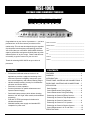
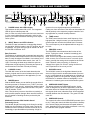
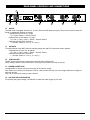
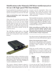
PROCESSOR
OWNER’S MANUAL
MSE-100A
MULTIBAND SOUND ENHANCEMENT PROCESSOR
MSE-100A
MULTIBAND SOUND ENHANCEMENT PROCESSOR
Congratulations on your choice of processors — you have
purchased one of the finest stereo processors on the
market today. This unit was developed using the expertise
of professional sound engineers and working musicians.
You will find that your new NADY AUDIO MSE-100A has
superior performance and greater flexibility than any other
enhancer/exicter in its price range. Please read this manual carefully to get the most out of your new unit.
Date of Purchase __________________________________________
Dealer’s Name ____________________________________________
City ______________________________________________________
State ____________________________________________________
Zip ______________________________________________________
Model # __________________________________________________
Serial # __________________________________________________
Thanks for selecting NADY AUDIO as your choice in
processors.
FEATURES
•
•
•
•
•
•
•
CONTENTS
FEATURES ..................................................................3
Professional multiband enhancer/exciter for all
applications provides a subjective loudening of the
audio and improves intelligibility, bass punch, presence and transparency and reduces listening fatigue
Variable sound processing circuitry for simultaneous
enhancer and exciter effects
Dual-mono or stereo operation
Surround processor for spatial enhancement and
improved stereo imaging
Dual-mode bass processor (which allows choosing
between “soft” and “tight” bass sounds; and multiband
processing
XLR and 1/4”TRS input/outputs for balanced or
unbalanced operation
Shielded internal power supply and standard IEC
receptacle for power cord.
WARNING ....................................................................4
INTRODUCTION..........................................................5
FRONT PANEL CONTROLS AND CONNECTIONS ..6
REAR PANEL CONTROLS AND CONNECTIONS ....7
APPLICATION..............................................................8
Basic Settings ............................................................8
Sound Enhancement During Replay ........................8
Sound Enhancement During Recording ....................8
Enhancing the Sound of Effects Devices ..................8
Enhancing the Sound of Tape Duplications ..............9
Enhancing the Sound of Instruments ........................9
Enhancing the Sound of P.A. Systems ......................9
Enhancing the Sound of Monitor Systems ................10
Sound Enhancement in Hi Fi and Video ..................10
SPECIFICATIONS ......................................................10
3
WARNING
An equilateral triangle enclosing a lightening flash/arrowhead symbol is
intended to alert the user to the presence of uninsulated “dangerous
voltage” within the product’s enclosure which may be of sufficient
magnitude to constitute a risk of electric shock.
ATTENTION: RISQUE DE CHOC ELECTRIQUE NE PAS OUVRIR
An equilateral triangle enclosing an exclamation point is intended to alert
the user to the presence of important operating and service instructions in
the literature enclosed with this unit.
IMPORTANT SAFETY INSTRUCTIONS
When using this electronic device, basic precautions should always be taken, including the following:
1. Read all instructions before using the product.
2. Do not use this product near water (e.g., near a bathtub, washbowl, kitchen sink, in a wet basement, or near a
swimming pool, etc.).
3. This product should be used only with a cart or stand that will keep it level and stable and prevent wobbling.
4. This product, in combination with headphones or speakers, may be capable of producing sound levels that
could cause permanent hearing loss. Do not operate for a long period of time at a high volume level or at a
level that is uncomfortable. If you experience any hearing loss or ringing in the ears, you should consult an
audiologist.
5. The product should be positioned so that proper ventilation is maintained.
6. The product should be located away from heat sources such as radiators, heat vents, or other devices
(including amplifiers) that produce heat.
7. The product should be connected to a power supply only of the type described in the operating instructions or
as marked on the product. Replace the fuse only with one of the specified type, size, and correct rating.
8. The power supply cord should: (1) be undamaged, (2) never share an outlet or extension cord with other
devices so that the outlet’s or extension cord’s power rating is exceeded, and (3) never be left plugged into
the outlet when not being used for a long period of time.
9. Care should be taken so that objects do not fall into, and liquids are not spilled through, the enclosure’s
openings.
10. The product should be serviced by qualified service personnel if:
A.
The power supply cord or the plug has been damaged.
B.
Objects have fallen into, or liquid has been spilled onto the product.
C. The product has been exposed to rain.
D. The product does not appear to operate normally or exhibits a marked change in performance.
E.
The product has been dropped, or the enclosure damaged.
11. Do not attempt to service the product beyond what is described in the user maintenance instructions. All
other servicing should be referred to qualified service personnel.
4
INTRODUCTION
In the last two decades, sound enhancement systems such as enhancers, exciters, psycho-acoustic processors etc. have
become an indispensable aid in the studio and have found widespread application in almost all film, broadcast and recording productions as well as in P.A. and sound reinforcement systems.
Basically, several principles of sound enhancement prevail in today’s market. The sound improving effect produced by the
enhancer is based on program-dependent phase shifting with the goal of enlarging the pulse width. In contrast, psychodynamic processors use a dynamic frequency correction of the program material and therefore enrich the program material
with high-frequency processing.
Conventional units often may work perfectly on pop music, but when processing acoustic instruments, the result is aggressive and unnatural. Enhancers are preferable for processing classical music and acoustic instruments. The result is a “softer”, unobtrusive transparency and an increased richness in sound. However, to make a pop recording more “aggressive”,
to set up a sound system for maximum intelligibility or to give a rhythm/bass guitar the necessary “punch”, it is recommended to process the high-frequency range with an Exciter.
The new VSP (Variable Sound Processing) circuit used in the MSE-100A, allows for variable fading over from enhancer to
exciter mode. With the PROCESS control clockwise, the Exciter circuit increasingly provides a variable and carefully
adjusted processing of high frequencies. The result is an increased brilliance and transparency. Fading over from one
effect to the other can thus adapt the effects perfectly to the respective program material.
The MSE-100A utilizes state-of-the-art level-independent enhancer circuitry which completely eliminates the problem of
restricted leveling capacity in previous, conventional units. Consequently, the DRIVE control to be found on conventional
exciters, which adapts the devices to different input levels, could be omitted on the MSE-100A. Thus, previous common
problems such as insufficient or excessive signal processing are eliminated.
The MSE-100A is equipped with a separate bass processor, which allows for sound enhancement in the lower frequency
band. A newly developed “Dual Mode” circuit allows you to vary between two different bass sounds from “soft” to “tight”.
Processing the bass range provides the optimum complement to high-frequency processing and opens up new dimensions
in the field of sound enhancement.
The MSE-100A can be used wherever professional sound improvement is required. This unit not only enhances the presence
and clarity of the program material, but also adds power to the bass frequencies. In addition it provides improved spatial definition.
These qualities make this unit an indispensable tool for many applications. For example, the MSE-100A produces a
greater penetration of sound, which is invaluable in improving the audio quality of radio and television transmissions. The
sound improvement offered by the MSE-100A is also perfectly suited to the demands of the recording industry. The following operational manual will introduce you to the MSE-100A and its various functions. After reading the manual carefully,
make sure it is always on hand for future reference.
5
FRONT PANEL CONTROLS AND CONNECTIONS
2
3
2
4
5
6
7
8
9
1. POWER Switch with LED Indicator
This switches the AC power ON or OFF. The integrated
LED will light to indicate power ON.
Note: In order to avoid possible undesired noise transients
in a live sound reinforcement application, switch on the
power to your MSE-100A before switching on the amplification system.
3
4
5
6
7
1
quencies for more signal transparency and brilliance.
Fading over from one effect to the other can thus adapt the
effects perfectly to the respective program material to suit
any application or personal sound preference.
5. TUNE control
The TUNE control sets the lower cutoff frequency of the
high-pass filter. Using this control you can select the frequencies that are routed to the Natural Sonic Processor.
The cut-off frequency can be adjusted within a range of 1
to 8 kHz.
2. IN/OUT Buttons and LED Indicators
The IN/OUT button activates the corresponding channel
into operation. With the button in the OUT position, the unit
is bypassed. The green LED will light to indicate “IN” and
the red LED will indicate “OUT”.
6. PROCESS control
The PROCESS control determines the function of the
device. Turning the control clockwise increasingly activates the Exciter mode.
Note: That for input signals that already include sufficient
treble content, such as classical music or acoustic instruments, generally the setting should emphasize the Exciter
mode. However, when processing, for instance, a
“slapped” bass guitar, the “Exciter” setting should dominate. Experiment for the sound you like.
Bass Processor
The Enhancer is equipped with a separate bass processor
which provides sound enhancement in the lower frequency
band. A newly developed “Dual Mode” circuit allows you to
vary between two different bass sounds, from “soft” to
“tight”. Processing the bass range allows the optimum
complement to high-frequency processing and opens up
new dimensions in the field of sound processing.
3. LOW MIX Control
The LOW MIX control of the low band determines the
amount of signal used for sound enhancement (from zero
to six). The setting depends on the application you are
addressing.
7. HIGH MIX control
The HIGH MIX control of the high band determines the
amount of signal used for sound enhancement (from zero
to six). It would depend on the application as to whether a
high-quality system is to be given the “finishing touch” with
the Enhancer, or whether maximum intelligibility is to be
achieved in a relatively poor sound reinforcement system.
4. MODE Buttons
With the MODE button you can define the sound effect of
the bass processor. If the button is on (“TIGHT”) the bass
will sound “dry” and “punchy”, whereas the released switch
mode (“SOFT”) creates a warm and full bass. The yellow
LED will indicate “TIGHT”.
Note: That the bass processor should be set carefully to
avoid possible speaker damage. Most near-field monitors
are not capable of handling the bass produced by the
Enhancer.
8. SURROUND IN/OUT Button
This button activates the SURROUND section. As this
mode is designed only for stereo applications, note that
this button has to be released when processing two separate signals (dual mono) otherwise there will be undesired
crosstalk between the two channels. The green LED indicates “IN”.
9. SURROUND Control
This controls the effect of the SURROUND processor (zero
to six). Turning the control clockwise improves the intensity
of the stereo imaging and increases the spatial enhancement, depending on the signal being processed. It can only
be used with stereo program material.
Multiband Processor With Variable Sound
Processing Circuit
The Variable Sound Processing circuit allows for variably
fading over from Enhancer to Exciter mode. Turning the
PROCESS control clockwise activates the Exciter circuit
increasingly to provide additional processing of high fre6
REAR PANEL CONTROLS AND CONNECTIONS
13
14
12
11
10
11
10
10. INPUTS
The MSE-100A is equipped with both 1/4” (6.3mm) TRS and XLR audio input jacks. These can be used for either balanced or unbalanced operation as follows:
• Unbalanced use of mono 1/4” plugs:
Tip = Signal, Sleeve = Ground / Shield.
• Balanced use of TRS stereo 1/4” plugs:
Tip = hot (+), Ring = cold (-), Sleeve = Ground / Shield.
• Balanced use with XLR connectors:
1 = Ground / Shield, 2 = hot (+), 3 = cold (-).
11. OUTPUTS
The audio outputs of the MSE-100A are matching phone jack and XLR connectors wired in parallel.
• Balanced use of stereo 1/4” jack/plugs:
Tip = hot (+), Ring = cold (-), Sleeve = Ground / Shield
• Balanced use with XLR connectors:
1 = Ground / Shield, 2 = hot (+), 3 = cold (-).
12. FUSE HOLDER
The IEC power socket has an integral fuse holder that takes a 20mm fuse.
NOTE: Always replace a blown fuse with the same type as specified on the rear of the unit.
13 . POWER CONNECTION
A standard IEC AC power socket for connecting to the main AC supply.
Note: Before you connect your Enhancer to the AC, please make sure that your local voltage matches the voltage required by the unit!
Note: Do not remove the center ground conductor.
14 . VOLTAGE SELECTOR SWITCH
For selecting the proper voltage (115/230VAC) to match the power supply in your area.
7
APPLICATIONS
BASIC SETTINGS
We recommend setting the controls as indicated in the following three sections. This will give you a better idea of
the switch and control functions:
1.
2.
3.
3.
Check your settings by making an A/B comparison using the IN/OUT switch.
SOUND ENHANCEMENT DURING RECORDING
The sound enhancing effect can be increased by using the
MSE-100A, not only during replay, but during actual
recording. This method of sound processing is recommended, in particular, if the subsequent storage medium is
of poor quality. When doing tape duplications, the
enhancer signal added during the recording will compensate for the loss in quality which occurs when several generations of copies are subsequently made from the master
tape.
Set the MSE-100A channel (1 or 2) to bypass
mode (the mode switch OUT and the red LED lit).
Set the LOW Mix and the TUNE center position
and the PROCESS controls fully counterclock
wise.
Turn the MIX controls fully CCW and press the
IN/OUT switch (green IN LED lit). Now turn the
LOW MIX controls counterclockwise from the
center position and the HIGH MIX controls
slowly clockwise until the fundamental bass and
high frequencies become more emphasized and
the sonic image begins to “open up” or to
“widen”.
The quality of the sound enhanced signal can be
adapted to the program material by varying the
LOW MIX controls and the TUNE controls.
In this scenario, insert the MSE-100A directly after the
master output of the mixer into the recording path of the
master or multi-track machine. Set up the unit as described above in “Sound Enhancement During Replay”. In
particularly difficult cases, we recommend using the MSE100A both during both recording and replay.
When using enhancers or exciters, it is easy to get carried
away. Therefore, we recommend regular A/B comparisons
(IN/OUT) while setting the controls, in order to constantly
check the signals integrity. Rule of thumb: the enhancer’s
effect should only be noticeable when it is lacking, but not
when it is present! Listening at high volume levels over
long periods (in studios, for example) leads to listening
fatigue and thus reduces sensitivity to higher frequencies.
Regular pauses keep your hearing “healthy” and helps you
avoid exaggerated sound processing.
Using the MSE-100A during recording
SOUND ENHANCEMENT DURING REPLAY
For this application, the MSE-100A follows the master or
multi-track recorder, i.e., inserted between tape machine
and mixer (or amplifier). Of course, a cassette recorder, or
similar equipment can also be used as a signal source. If
a companding noise reduction system is used in this situation, it should precede the MSE-100A.
Using the MSE-100A in a mixer send/return loop
ENHANCING THE SOUND OF EFFECTS DEVICES
Often, signal processing units such as flangers, phasers,
distortion, chorus, delay and reverb units etc. considerably
limit the signal’s sound quality. Here too, the MSE-100A
will be of help. Simply inset the unit after the effects
device. If there are several devices, insert the MSE-100A
as the last unit in the chain.
Using the MSE-100A during replay
1.
2.
Set up your equipment as usual, with the effects
switched off.
Turn on the MSE-100A and adjust the controls
as desired (if necessary, read above
“Basic Settings” once again).
8
APPLICATIONS
ENHANCING THE SOUND OF TAPE DUPLICATIONS
Even under the most favorable of conditions, presence,
liveliness and transparency of the program material will
suffer during each copying process. These losses are particularly obvious when copying cassettes while simultaneously using a noise reduction system. With the MSE100A, losses during tape duplication can be avoided or
compensated for, provided that the original is of good
enough quality, with only low noise levels. It is even possible to produce “super” copies, which sound even better
than the original. For this application, the MSE-100A is
inserted between the line outputs of the source machine
and the inputs of the target machine. Machines with posthead listening control (setting “Tape Monitor”) allow you to
check the quality of the copy while duplicating.
Note: That low-level signal sources such as microphones,
guitars, etc., should pass through a preamplifier before the
processing stage, since the MSE-100A is a line-level
device (120 to +10 dBu).
ENHANCING THE SOUND OF P.A. SYSTEMS
If used in P.A. and other sound reinforcement systems, for
background or live music, the MSE-100A offers dramatic
advantages:
1.
If the tape noise is fairly high, a different strategy is
required, since the MSE-100A can effectively process the
frequency ranges in which the most predominant noise
portions can be found. We recommend attenuation of
noisy high frequencies, either with an equalizer or preferably with a “single-ended” noise reduction system. The
MSE-100A will process those frequencies with all of their
natural clarity, but without the tape noise.
In audio systems for announcements and background music, the MSE-100A is placed in a
similar way to recording and tape duplication—
directly before the power amp. The intelligibility
and range of your system will be improved and
the sonic image will become clear and transparent, even at low volume levels. You will quickly
find that the MSE-100A can be a valuable tool
in solving otherwise difficult audio problems.
For instance, in clubs, you do not need to
constantly readjust the high frequencies as the
room becomes increasingly crowded. With the
MSE-100A, you will thus be able to protect your
speaker system and the hearing of your visitors.
Also, background music in bars and restaurants
can be heard more easily while keeping the
volume more manageable.
2.
Using the MSE-100A during tape duplication
ENHANCING THE SOUND OF INSTRUMENTS
The bandwidth of most electronic musical instruments is
limited by its “sampling rate”. The MSE-100A can improve
the sound so that the synthesizers, samplers, and drum
machines have a more natural and transparent sound.
With the MSE-100A, even tiny details within the sound of
acoustic musical instruments such as guitars, etc., can be
emphasized without affecting the overall sound of the
instrument. Drum instruments, such as toms, bass drums,
etc., benefit from such “punch” and thus achieve a more
powerful, precise and defined sound.
The sound of any P.A. system will be improved
by the MSE-100A. For example, vocals and
speech will be considerably more transparent
and intelligible, and the instruments can be
distinguished more easily.
Using the MSE-100A in the P.A. System
The MSE-100A will increase the speaker system’s acoustic performance and its ability to penetrate a room, particularly in places with difficult acoustics. The system will also
need less effective amplifier power, since the subjectively
heard volume level increases. Powerful and detailed
sound reproduction can thus be achieved in “weak” systems. Often the MSE-100A can help you prevent spending a small fortune on upgrading your entire system.
Processing the sound of a synthesizer with the
MSE-100A
9
APPLICATIONS
Note: If the P.A. speakers are operated in mono,
the second channel of the MSE-100A can be used for
another application.
ENHANCING THE SOUND OF MONITOR SYSTEMS
The MSE-100A can be effectively used to improve the
sound of stage monitor systems. Here intelligibility and
transparency are of paramount importance during sound
reproduction. For this purpose, the MSE-100A is inserted
either in the “monitor send” path or between monitor mixer
and power amplifier.
Using the MSE-100A in a Hi Fi system
The NADY MSE-100 A can be used for improving audio
for:
SOUND ENHANCEMENT IN HI FI AND VIDEO
Of course, the MSE-100A can also be used in Hi Fi and
video applications. The unit is simply placed between the
signal source (cassette recorder, tuner, VCR, etc.) and the
power amplifier. We recommend using the “tape monitor”
inputs most preamplifiers provide, thus the MSE-100 A can
be switched into any signal source.
•
•
•
•
Disc and tape recordings
Recorded video and audio cassettes
Radio reception
TV reception
SPECIFICATIONS
INPUT
MULTIBAND PROCESSOR
Type ..................................RF filtered, servo-balanced input
Connectors ......................XLR and 1/4” TRS jacks
Impedance ......................24K Ω balanced,
12K Ω unbalanced
Max. Input Level ..............+21dBu balanced and unbalanced
CMRR ..............................Typically 40dB, > 55dB @ 1kHz
Type ..................................“Natural Sonic” processor with
“Variable Sound Processing”
Tune Control ....................Variable (1 to 8kHz).
Process Control ..............Variable (Enhancer to Exciter)
High Mix Control ............Variable (0 to 6; Off to Max.)
FUNCTION SWITCHES
OUTPUT
IN/OUT switches both channels, with red/green LED status
indicators
Type ..................................DC-decoupled unbalanced
output stage
Connectors ......................XLR and 1/4” TRS jacks
Impedance ......................90 Ω balanced, 45 Ω unbalanced
Max. Output Level ..........+21dBu balanced and unbalanced
Bandwidth........................20Hz to 20kHz, +0/-0.5dB
Frequency Response......5Hz to 100kHz, +0/-3dB
Noise ................................> -95dBu, unweighted, 22Hz to
22kHz
THD ..................................0.008% typically @ +4dBu,1kHz
IMD....................................0.01% typically, SMPTE
Crosstalk..........................< -86dB, 22Hz to 22kHz
POWER SUPPLY
AC Voltage ......................100-120/60HZ or 200-240/50HZ
VAC as marked
Power consumption........9 watts
Fuse ................................T250mA, 250V
Power Cord Connector ..Standard IEC receptacle
DIMENSION
1.75” X 19” X 7.8” (44 X 482 X 197mm.)
BASS PROCESSOR
WEIGHT
Type ..................................“Dual Mode” Bass Processor
Switches the bass sound
from “Soft” to “Tight”
Low Mix Control ..............Variable (0 to 6; Off to Max.)
6.2 lbs. (2.8 Kg.)
Specifications and design subject to change without prior notice
for improvement purposes
10
SERVICE FOR YOUR NADY AUDIO PRODUCT
(U.S.) Should your NADY AUDIO product require service, please contact the Nady Service Department via telephone at (510) 652-2411, or e-mail at [email protected].
(International) For service, please contact the NADY AUDIO distributor in your country through the dealer from
whom you purchased this product.
DO NOT ATTEMPT TO SERVICE THIS UNIT
YOURSELF AS IT CAN BE DANGEROUS AND
WILL ALSO VOID THE WARRANTY.
NADY SYSTEMS, INC. • 6701 SHELLMOUND STREET, EMERYVILLE, CA 94608
Tel: 510.652.2411 • Fax: 510.652.5075 • www.nady.com