1
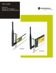
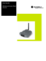
User Guide
Wireless Access Point
WA840G
WARNING: TO PREVENT FIRE OR SHOCK HAZARD, DO NOT EXPOSE THIS PRODUCT TO RAIN OR MOISTURE. THE UNIT MUST NOT BE
EXPOSED TO DRIPPING OR SPLASHING. DO NOT PLACE OBJECTS FILLED WITH LIQUIDS, SUCH AS VASES, ON THE UNIT.
CAUTION: TO ENSURE REGULATORY COMPLIANCE, USE ONLY THE PROVIDED POWER AND INTERFACE CABLES.
CAUTION: DO NOT OPEN THE UNIT. DO NOT PERFORM ANY SERVICING OTHER THAN THAT CONTAINED IN THE INSTALLATION AND
TROUBLESHOOTING INSTRUCTIONS. REFER ALL SERVICING TO QUALIFIED SERVICE PERSONNEL.
This device must be installed and used in strict accordance with the manufacturer’s instructions as described in the user documentation that comes with the
product.
Postpone router installation until there is no risk of thunderstorm or lightning activity in the area.
Do not overload outlets or extension cords, as this can result in a risk of fire or electric shock. Overloaded AC outlets, extension cords, frayed power cords,
damaged or cracked wire insulation, and broken plugs are dangerous. They may result in a shock or fire hazard.
Route power supply cords so that they are not likely to be walked on or pinched by items placed upon or against them. Pay particular attention to cords where
they are attached to plugs and convenience receptacles, and examine the point where they exit from the product.
Place this equipment in a location that is close enough to an electrical outlet to accommodate the length of the power cord.
Place this equipment on a stable surface.
When using this device, basic safety precautions should always be followed to reduce the risk of fire, electric shock and injury to persons, including the
following:
•
Read all of the instructions {listed here and/or in the user manual} before you operate this equipment. Give particular attention to all safety precautions.
Retain the instructions for future reference.
•
Comply with all warning and caution statements in the instructions. Observe all warning and caution symbols that are affixed to this equipment.
•
Comply with all instructions that accompany this equipment.
•
Avoid using this product during an electrical storm. There may be a risk of electric shock from lightning. For added protection for this product during a
lightning storm, or when it is left unattended and unused for long periods of time, unplug it from the wall outlet, and disconnect the cable system. This will
prevent damage to the product due to lightning and power surges.
•
Operate this product only from the type of power source indicated on the product’s marking label. If you are not sure of the type of power supplied to your
home, consult your dealer or local power company.
•
Upon completion of any service or repairs to this product, ask the service technician to perform safety checks to determine that the product is in safe
operating condition.
It is recommended that the customer install an AC surge protector in the AC outlet to which this device is connected. This is to avoid damaging the equipment by
local lightning strikes and other electrical surges.
Different types of cord sets may be used for connections to the main supply circuit. Use only a main line cord that complies with all applicable product safety
requirements of the country of use.
Installation of this product must be in accordance with national wiring codes.
Place unit to allow for easy access when disconnecting the power cord/adapter of the device from the AC wall outlet.
Wipe the unit with a clean, dry cloth. Never use cleaning fluid or similar chemicals. Do not spray cleaners directly on the unit or use forced air to remove dust.
This product was qualified under test conditions that included the use of the supplied cables between system components. To be in compliance with regulations,
the user must use these cables and install them properly. Connect the unit to a grounding type AC wall outlet using the power adapter supplied with the unit.
Do not cover the device, or block the airflow to the device with any other objects. Keep the device away from excessive heat and humidity and keep the device
free from vibration and dust.
Installation must at all times conform to local regulations.
FCC Compliance Class B Digital Device
This equipment has been tested and found to comply with the limits for a Class B digital device, pursuant to Part 15 of the FCC Rules. These limits are designed
to provide reasonable protection against harmful interference in a residential environment. This equipment generates, uses, and can radiate radio frequency
energy and, if not installed and used in accordance with the instructions, may cause harmful interference to radio communications. However, there is no
guarantee that interference will not occur in a particular installation. If this equipment does cause harmful interference to radio or television reception, which can
be determined by turning the equipment off and on, the user is encouraged to try to correct the interference by one of the following measures:
•
Reorient or relocate the receiving antenna.
•
Increase the separation between the equipment and receiver.
•
Connect the equipment into an outlet on a circuit different from that to which the receiver is connected.
•
Consult the dealer or an experienced radio/TV technician for help.
CAUTION: Changes or modifications not expressly approved by Motorola for compliance could void the user’s authority to operate the equipment.
Canadian Compliance
This Class B digital apparatus meets all requirements of the Canadian Interference Causing Equipment Regulations. Cet appareil numérique de la classe B
respects toutes les exigences du Règlement sur le matériel brouilleur du Canada.
FCC Declaration of Conformity
Motorola, Inc., Broadband Communications Sector, 101 Tournament Drive, Horsham, PA 19044, 1-215-323-1000, declares under sole responsibility that the
WR850G, WE800G, WA840G, and BR700 comply with 47 CFR Parts 2 and 15 of the FCC Rules as a Class B digital device. This device complies with Part 15
of FCC Rules. Operation of the device is subject to the following two conditions: (1) This device may not cause harmful interference, and (2) this device must
accept any interference that may cause undesired operation.
Copyright © 2003 Motorola, Inc.
All rights reserved. No part of this publication may be reproduced in any form or by any means or used to make any derivative work (such as
translation, transformation or adaptation) without written permission from Motorola, Inc.
Motorola reserves the right to revise this publication and to make changes in content from time to time without obligation on the part of Motorola to
provide notification of such revision or change. Motorola provides this guide without warranty of any kind, either implied or expressed, including
but not limited to, the implied warranties of merchantability and fitness for a particular purpose. Motorola may make improvements or changes in
the product(s) described in this manual at any time.
MOTOROLA and the Stylized M Logo are registered in the US Patent & Trademark Office. Microsoft, Windows, Windows Me and Windows XP
are either registered trademarks or trademarks of Microsoft Corporation in the United States and/or other countries. Microsoft Windows screen
shots are used by permission of Microsoft Corporation. Wi-Fi is a registered trademark of Wireless Ethernet Compatibility Alliance, Inc. All other
product or service names are the property of their respective owners. © Motorola, Inc. 2003.
Contents
Section 1:Overview
Features ................................................................................................................ 1-3
Understanding Your User Guide ......................................................................... 1-4
Box Contents ........................................................................................................ 1-5
Wireless Connections .......................................................................................... 1-5
Access Point .......................................................................................................1-5
LAN1-5
TCP/IP.................................................................................................................1-6
Static IP Address...........................................................................................................1-6
Dynamic IP Address......................................................................................................1-6
Positioning Your Access Point ........................................................................... 1-7
Wireless Range...................................................................................................1-7
Technical Specifications................................................................................................1-8
Type of Networks.................................................................................................. 1-9
Access Point Mode..............................................................................................1-9
WDS Access Point Mode ....................................................................................1-9
Access Point Physical Description................................................................... 1-10
Back of Access Point.........................................................................................1-10
Front of Access Point ........................................................................................1-11
LED Description ................................................................................................1-12
Section 2:Installation
Hardware Setup .................................................................................................... 2-1
Antenna Installation.............................................................................................2-1
Access Point Physical Installation .......................................................................2-2
Horizontal Installation ....................................................................................................2-2
Vertical Installation ........................................................................................................2-3
Wall Mount Installation ..................................................................................................2-3
Electrical Connection to Access Point .................................................................2-7
Easy Software Setup ............................................................................................ 2-7
Manual Software Setup ........................................................................................ 2-8
Wired Connection to Access Point ......................................................................2-8
Wireless Connection to Access Point..................................................................2-9
Configure Your Computers................................................................................ 2-10
Configuring Windows 98SE and ME .................................................................2-11
Configuring Windows 2000 ...............................................................................2-13
Configuring Windows XP...................................................................................2-16
WA840G
I
CONTENTS
Configure Your Wireless Security Settings ......................................................2-19
Logging In .........................................................................................................2-19
Wireless Security Setup ....................................................................................2-20
Section 3:Configuration
Using the Web-Based Configuration Utility ........................................................3-1
Logging In ...........................................................................................................3-1
Navigation ...........................................................................................................3-2
Help, Restart, and Logout ...................................................................................3-2
Configuring Wireless Network Settings ..............................................................3-3
Basic Wireless Configuration ..............................................................................3-3
Configuring Wireless Security Settings ...............................................................3-5
Monitoring Wireless Access Points ...................................................................3-12
Advanced Wireless Configuration .....................................................................3-14
Configuring Control Panel Settings...................................................................3-17
Configuring Network Address ...........................................................................3-18
Configuring Device Security..............................................................................3-19
Updating Firmware............................................................................................3-20
Saving and Restoring Configuration Settings....................................................3-21
Section 4:Troubleshooting
Contact................................................................................................................4-1
Hardware Solutions...............................................................................................4-1
My computer is experiencing difficulty in connecting to the access
point.......................................................................................................................4-2
Software Solutions................................................................................................4-3
I would like to see if my Internet connection is live........................................................4-3
I cannot access the Configuration Utility for the access point. ......................................4-4
What if Pass Phrase isn’t supported? What do I enter for my
security? ................................................................................................................4-5
I cannot browse past the first screen of the Configuration Utility...................................4-6
Section 5:Glossary
II
WA840G
Section 1:Overview
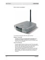
Congratulations on purchasing the Motorola Wireless Access Point
WA840G.
With the WA840G, you can network with everyone in your home or
small office — wirelessly. The centerpiece of a user-friendly wireless
network, the WA840G is a capable of providing data rates up to
54 Mbps, which is nearly 5 times faster than 802.11b networking.
Using the WA840G, you can effortlessly share files, pictures,
peripherals, printers and more with everyone else on the network. By
connecting a broadband modem (cable, DSL or other) and a router,
you can also share a single high speed Internet connection. That's
everyone online, all at the same time.
Because the access point is built with both the popular 802.11b
wireless standard and the new nearly 5-times-faster 802.11g
standard, your access point provides you the ultimate in flexibility and
speed. With Wi-Fi® Protected Access (WPA) included, your wireless
connections are robust and secure, giving you the security to
communicate without fear that your signal might be compromised.
Upgradeable firmware keeps the access point’s control software upto-date. The WA840G captures the latest technology in a package
that will stay current for many years, protect your home network, and
provide you with easy home network management.
WA840G
1-1
SECTION 1
OVERVIEW
Wireless Access Point WA840G
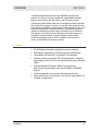
Your wireless access point offers these great features:
Wireless Connectivity
Connects your PC to your wireless network and allows you to
communicate unfettered. Using the 802.11g and 802.11b
wireless communication standards will ensure compliance with
current and future standards.
Secure Transmission
Protection against Internet intruders is crucial. The access point
supports single session encryption when communicating with just
the client, and it also supports network encryption when
communicating with surrounding wireless networks.
The access point supports Wi-Fi Protected Access (WPA) and
Media Access Control (MAC) filtering protocols, giving you the
choice to share your Internet connection with only those you
designate.
1-2
WA840G
OVERVIEW
SECTION 1
Your Motorola Wireless Access Point WA840G connects and
protects you. Built-in security coupled with upgradeable firmware
ensures your access point will work for you for years to come.
A Word about Data Rates: Data rate is the speed at which individual
bits of data flow through a channel. It is not the same speed at which
entire files are uploaded or downloaded. These speeds will vary, and
are often less than the maximum data rate. Upload and download
speeds are affected by several factors including, but not limited to:
the capacity of and the services offered by your cable operator or
broadband service provider, channel capacity, network traffic,
computer equipment, type of server, number of connections to
server, and availability of Internet router(s).
Features
WA840G
!
CD-ROM based Installation Assistant for easy installation
!
Web-based configuration of features using any web browser
!
Compatibility with both 802.11g and 802.11b standards
!
Wireless security using WPA, 802.1X Authentication, Temporal
Key Integrity Protocol (TKIP), and Advanced Encryption Standard
(AES)
!
Wireless Distribution System (WDS) mode supporting
peer-to-peer communication with other WA840G or WR850G
devices
!
Firmware upgrade to stay current with latest specification
!
Easily extend your home network in the office or other places, for
example, at tradeshows
1-3
SECTION 1
OVERVIEW
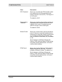
Understanding Your User Guide
The User Guide is divided into the following sections:
Overview
Describes the access point and its functions, the
technology used, and the recommended methods
for positioning the access point.
Installation
It is assumed that you will use the Installation
Wizard on the CD-ROM to setup your access point.
If not, refer to this section for instructions on getting
your access point up and running.
After you have completed this section, your access
point will be active and ready to work.
1-4
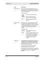
Configuration
Describes the Configuration Utility that manages
your access point.
Glossary
List of terms and acronyms.
WA840G
OVERVIEW
SECTION 1
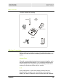
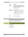
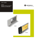
Box Contents
Your box contains the following:
Antenna
Ethernet
Cable
CD-ROM
Base Station Stand
WA840G
Power
Supply
Quick Start
Guide
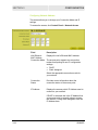
Wireless Connections
Before installing your wireless access point, please take a few
minutes to review the wireless networking functions described in this
section.
Access Point
Generally, access points wirelessly connect networks together, such
as your network with the Internet. Or, by configuring multiple clients
such as laptops, each using their own access point, you are able to
create your own private wireless Ad-Hoc network.
LAN
Local Area Network. A local area network provides a full-time,
high-bandwidth connection over a limited area such as a home,
building, or campus. Ethernet is the most widely used LAN standard.
WA840G
1-5
SECTION 1
OVERVIEW
TCP/IP
Transmission Control Protocol/Internet Protocol (TCP/IP) comprises
the backbone of the Internet. IP moves packets of data between
nodes while TCP verifies delivery from client to server. The device
you hook up to your wireless access point will identify itself with an IP
address so that the network will know where to retrieve and deposit
requested information.
Static IP Address
A static IP address is a fixed address that is assigned manually to a
device on the network. Static IP addresses must be unique and
cannot be shared, therefore they are used in situations where the
address should never change, like print servers or PC servers.
Dynamic IP Address
A dynamic IP address is a temporary IP number, dynamically or
randomly generated by a DHCP server. The address lasts only as
long as the server allots, usually in the space of a day or two. When
the IP address expires, the client is automatically reassigned a new
IP address, ensuring smooth communication.
1-6
WA840G
OVERVIEW
SECTION 1
Positioning Your Access Point
To achieve the best wireless performance, review these guidelines
before deciding where to place your access point:
!
Placing your base station in the physical center of your network is
the best location because the antenna sends out the signal in all
directions.
!
Placing the access point in a higher location, such as on top of a
cabinet, helps to disperse the signal cleanly, especially to
receiving locations on upper stories.
!
If possible, position your access point so there is a direct line of
sight between the access point and your other home network
devices.
!
Avoid placing the access point next to large solid objects like
computer cases, monitors, walls, fireplaces, etc. This helps the
signal penetrate more cleanly.
!
Other wireless devices like televisions, radios, microwaves and
2.4 GHz cordless telephones can interfere with the signal. Keep
devices away from the access point.
!
Mirrors, especially silver-coated, can reduce transmission
performance.
Wireless Range
The following describes different scenarios for the expected range of
the coverage area of the access point. This table is only a guide and
coverage varies due to local conditions.
WA840G
Data Rate
Open Area
Closed Area
54 Mbps
Up to 100 ft (30m)
Up to 60 ft (18m)
11 Mbps
Up to 900 feet (275 m)
Up to 160 feet (49 m)
5.5 Mbps
Up to 1300 feet (396 m)
Up to 200 feet (61 m)
2 or 1 Mbps
Up to 1500 feet (457 m)
Up to 300 feet (91 m)
1-7
SECTION 1
OVERVIEW
Technical Specifications
Your wireless access point uses a radio transmission technology
defined by the Institute of Electrical and Electronics Engineers (IEEE)
called 802.11 or Wi-Fi (Wireless Fidelity). This standard is subdivided
into distinct categories of speed and the frequency spectrum used,
designated by the lower case letter after the standard. For example,
your access point supports both the ‘b’ and ‘g’ specifications. The
802.11b specification transmits data rates up to 11 Mbps while the
802.11g specification transmits data rates up to 54 Mbps. These are
theoretical speeds so your performance may vary. The radio waves
radiate out in a donut-shaped pattern. The waves travel through walls
and floors, but transmission power and distance are affected. The
theoretical distance limit is 1,000 feet (305 meters), but actual
throughput and distance varies.
Both standards operate in the 2.4 GHz range, meaning other
electrical appliance also might interfere with the access point –
televisions, radios, microwave ovens, and 2.4 GHz cordless
telephones. Thus positioning your access point where it encounters
the least interference gains the greatest benefit to maintaining a
quality connection.
1-8
WA840G
OVERVIEW
SECTION 1
Type of Networks
Your access point can be used in several ways. The following
examples illustrate the flexibility of your WA840G. Some examples
require additional hardware.
Access Point Mode
In this mode, the WA840G connects wireless clients to a wired
Ethernet network. This example shows the most likely use for the
access point, because it shares an Internet connection with your
laptop or other wireless client.
WDS Access Point Mode
In this mode, the WA840G wirelessly connects its wireless clients to
other access points.
WA840G
1-9
SECTION 1
OVERVIEW
Access Point Physical Description
The following sections describe the physical characteristics of your
access point.
For instructions on installing your access point, see Section 2:
Installation.
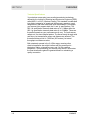
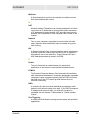
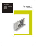
Back of Access Point
The following illustration shows the WA840G back panel:
Reset
Power
Power
Receptacle
1-10
LAN
LAN
Port
Antenna
Reset Antenna
Button
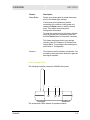
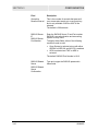
Feature
Description
Power
Receptacle
The receptacle where you plug in the power
adapter.
LAN Port
This port connects your access point to the
Internet, your LAN network, or PC using an
Ethernet cable. This allows communication
between the devices. The LAN port supports
either 10BASE-T or 100BASE-T transmission
speeds as well as straight-through and
Crossover Ethernet cables.
WA840G
OVERVIEW
SECTION 1
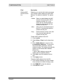
Feature
Description
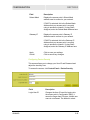
Reset Button
Resets your access point or resets the access
point to the default login settings.
If the access point experiences trouble
connecting to the Internet, briefly press and
release the Reset button to reset the access
point. This retains the access points
configuration information.
To reset the access point to the factory defaults,
while the access point is powered, press and
hold the Reset button for more than 5 seconds.
This clears the access point’s user settings,
including User ID, Password, IP Address, and
Subnet Mask. To re-configure the access point,
see Section 3: Configuration.
Antenna
The antenna used for wireless connections. You
are able to rotate and tilt the antenna to gain the
best signal reception.
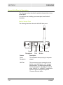
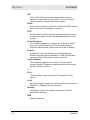
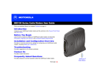
Front of Access Point
The following illustration shows the WA840G front panel:
1
r
we
Po
2
W
le
ire
3
ss
e
vic
De
The access point LEDs indicate its operational status.
WA840G
1-11
SECTION 1
OVERVIEW
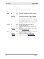
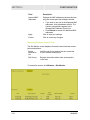
LED Description
The underlined items represent network activity.
LED
1 Power
Condition
Color
Status
ON
Green
The device is powered on and operating normally.
Blinking
Green
Firmware update is in progress.
Blinking/ON Red
2 Wireless
OFF
None
No mobile station or access point has been
associated with this device.
ON
Red
The wireless interface has been disabled by the
firmware.
ON/Blinking Green
3 Device
The power LED turns RED as soon as the reset
button is depressed. If the reset button is held down
for more than 5 seconds, the LED starts to blink
during which the access point’s default user name,
password and IP address will be restored. The LED
then turns OFF until the reset button is released. The
power LED blinks RED if the firmware is corrupted
indicating the firmware needs to be restored.
OFF
None
802.11b/802.11g connection exists in this wireless
domain/active traffic present.
No external Ethernet device has been attached and
detected. The Ethernet link is down.
ON/Blinking Amber 10BaseT link detected/active traffic present.
ON/Blinking Green
1-12
100BaseT link detected/active traffic present.
WA840G
Section 2:Installation
To get your network up and running:
!
Set up your hardware.
!
Insert the CD-ROM for Software Setup. Follow the prompts.
If you prefer to set up the access point’s software manually, refer to
the Manual Software Setup found in this section.
The following sections provide detailed instructions for completing
these tasks.
Hardware Setup
Hardware setup includes:
!
Antenna Installation: verifying the antenna is connected to the
access point.
!
Physical Installation: where you physically place your access
point.
!
Electrical Connection: how to power your access point.
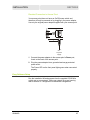
Antenna Installation
When shipped, the antenna is connected to the access point. If for
some reason you need to detach and reattach the antenna to the
main access point:
WA840G
1
Locate the antenna threaded knob on the back of the access
point.
2
To remove the antenna, unscrew the antenna connector
counter-clockwise
2-1
SECTION 2
INSTALLATION
3
To reattach the antenna, screw the antenna connector clockwise
on to the threaded knob until firmly seated. Do not overtighten.
Access Point Physical Installation
You can install the access point horizontally or vertically. The access
point can also be mounted on a wall.
Horizontal Installation
1
2-2
Place the access point in the desired location and follow the
procedures below for connecting and configuring the access
point.
WA840G
INSTALLATION
SECTION 2
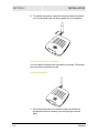
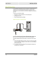
Vertical Installation
1
Insert the access point into the supplied base. Ensure that the
antenna’s location is on top. The access point’s foot slides snugly
into the base to keep the access point stable.
2
Follow the installation procedures for connecting and configuring
the access point.
Wall Mount Installation
If you mount the access point on the wall, you must:
!
Position the access point as specified by the local or national
codes governing residential or business communications
services.
!
Follow all local standards for installing a network interface
unit/network interface device (NIU/NID).
If possible, mount the access point to concrete, masonry, a wooden
stud, or other solid wall material. Use anchors when necessary; for
example, if you must mount the access point on drywall.
WA840G
2-3
SECTION 2
INSTALLATION
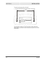
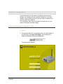
To mount your access point on the wall:
1
Print the Wall Mounting Template shown on this page:
3.15”
[80.00mm]
MODEL WA840G
INPUT VOLTAGE: +5VDC, 2A
FCC ID: F2NWA840G
PART NUMBER: AAAAAA-BBB-CC
S/N: PPPPMMYJJJSSSSSCAABBCCCC
MODEL: WA840G
Tested To Comply
With FCC Standards
WIRELESS MAC: AB CD EF 01 23 45
FOR HOME OR OFFICE USE
MADE IN TAIWAN
The illustration is drawn at a one-to-one scale, which means that
when printed, it provides the exact dimensions required to mount the
access point.
2-4
WA840G
INSTALLATION
SECTION 2
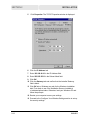
2
Click the Print icon or choose Print from the File menu to display
the Print dialog box:
In both the Pages from and to fields, enter the page number on
which the Wall Mounting Template appears.
Be sure you print the template at 100% scale and that Fit to page
is not checked in the Print dialog box.
3
Click OK.
4
Measure the printed template with a ruler to ensure that it is the
correct size.
5
Use a center punch to mark the center of the holes on the wall.
6
On the wall, locate the marks for the mounting holes you just
made.
WARNING!
Before drilling holes, check the structure for potential
damage to water, gas, or electric lines.
7
WA840G
Drill the holes to a depth of at least 3.8 cm (1½ inches).
2-5
SECTION 2
INSTALLATION
8
If necessary, seat an anchor in each hole. Use M5 x 38 mm
(#10-16 x 1½ inch) screws with a flat underside and maximum
screw head diameter of 10.5 mm to mount the access point.
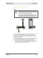
9
Using a screwdriver, turn each screw until part of it protrudes
from the wall, as shown:
!
There must be 4.0 mm (.16 inches) between the wall and the
underside of the screw head.
!
The maximum distance from the wall to the top of the screw
head is 7.6 mm (.3 in).
7.6 mm (.3 inches)
maximum
10.5 mm (.4 inches)
maximum
4.0 mm
10 Remove the front two plastic feet, nearest to the LED panel, from
the bottom of the access point to uncover the keyholes.
11 Place the access point so the keyholes are above the mounting
screws.
12 Slide the access point down until it stops against the top of the
keyhole opening.
13 Follow the installation procedures for connecting and configuring
the access point.
2-6
WA840G
INSTALLATION
SECTION 2
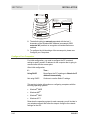
Electrical Connection to Access Point
Your access point does not have an On/Off power switch and
therefore will only be powered on by plugging in the power adapter.
Use only the original power adapter supplied with your access point.
To power
supply
1
Connect the power adapter to the access point’s Power port,
found on the back of the access point.
2
Plug the power adapter into a grounded and surge-protected
power outlet.
The Power LED on the front panel lights green when connected
properly.
Easy Software Setup
Run the Installation Wizard program from the supplied CD-ROM to
quickly set up your network. Once your network is up and running,
refer to Section 3: Configuration for advanced configuration.
WA840G
2-7
SECTION 2
INSTALLATION
Manual Software Setup
If you’d prefer to manually set up your network, use this section to
configure it. This section details the physical connection of the
access point to your network as well as the configuration needed by
your PC.
To set up your wireless network:
!
Physically connect and power on the access point
!
Configure your PCs
!
Enter Wireless Security settings
Wired Connection to Access Point
Reset
Power
LAN
Antenna
If you are connecting your PC with an Ethernet cable to the access
point, your PC must be installed first with an Ethernet adapter.
You need one Ethernet cable for this procedure, to connect the PC to the access
point.
2-8
1
Using the supplied Ethernet cable, connect one end of the cable
to your PC’s Ethernet adapter and the other end to the LAN port
on the access point.
2
To configure the initial settings of the access point, please see
Configure your Computers.
WA840G
INSTALLATION
SECTION 2
Wireless Connection to Access Point
WARNING!
When first configuring your access point, it is
recommended that use an Ethernet cable. Performing
the INITIAL configuration using a wireless connection
is not secure and is not recommended.
After you have finished the initial configuration of the
access point, your connection will be secure and you
can safely use either a wired or wireless connection.
Reset
Power
LAN
Antenna
If you are connecting your client wirelessly to the access point, you
can use the Motorola WPCI810G, a wireless PCI card for your
desktop PC. If you have a laptop, the Motorola WN825G wireless
PC card provides access.
The WN825G and WPCI810G are not supported under Windows 95,
98, or NT. Windows 98SE, ME, 2000, and XP are supported.
1
WA840G
To connect the PC to the access point through a wireless
connection, ensure the PC’s wireless adapter SSID (Service Set
Identifier) is set the access point’s SSID.
2-9
SECTION 2
INSTALLATION
MODEL WA840G
INPUT VOLTAGE: +5VDC, 2A
FCC ID: F2NWA840G
PART NUMBER: AAAAAA-BBB-CC
S/N: PPPPMMYJJJSSSSSCAABBCCCC
MODEL: WA840G
Tested To Comply
With FCC Standards
WIRELESS MAC: AB CD EF 01 23 45
FOR HOME OR OFFICE USE
MADE IN TAIWAN
MODEL WA840G
INPUT VOLTAGE: +5VDC, 2A
FCC ID: F2NWA840G
PART NUMBER: AAAAAA-BBB-CC
S/N: PPPPMMYJJJSSSSSCAABBCCCC
MAC address
MODEL: WA840G
Tested To Comply
With FCC Standards
WIRELESS MAC: AB CD EF 01 23 45
FO R HOM E OR OF FICE U SE
MADE IN TAIWAN
2
The default setting is motorola appended with the last 3
characters of the Wireless MAC address (an example SSID:
motorola 345) and that no encryption and authentication are
enabled.
3
To configure the initial settings of the access point, please see
Configure your Computers.
Configure Your Computers
For initial configuration, you need to configure the PC’s network
setting to specify a static IP address for the computer that is going to
communicate with the access point.
After initial configuration:
If…
Then…
Using DHCP
Reconfigure the PC’s settings to Obtain An IP
Address Automatically.
Not using DHCP
Continue to use the Static IP settings.
This section includes information on configuring computers with the
following operating systems:
®
!
Windows 98SE
!
Windows ME
!
Windows 2000
!
Windows XP™
®
®
Determine the operating system for each computer you will include in
your wireless network and follow the steps to configure the network
settings for that PC.
2-10
WA840G
INSTALLATION
SECTION 2
Configuring Windows 98SE and ME
WA840G
1
Click Start.
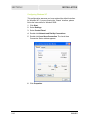
2
Select Settings > Control Panel.
3
Double-click Network. The Network window is displayed:
4
On the Configuration tab, select the TCP/IP line the for the
appropriate Ethernet adapter on your PC. There may be multiple
adapters installed – choose only the one that is configured for
your adapter. In the example above, a 3Com Ethernet adapter
card is installed and is the appropriate choice.
2-11
SECTION 2
INSTALLATION
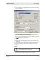
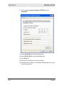
5
Click Properties. The TCP/IP Properties window is displayed:
6
Click the IP Address tab.
7
Enter 192.168.40.10 in the IP Address field.
8
Enter 255.255.255.0 in the Subnet Mask field.
9
Click OK.
10 Click the Gateway tab and confirm that the Installed Gateway
field is blank.
11 Click OK twice. Windows may ask for the Windows Installation
disk. First check to see if the installation files are installed at
c:\windows\options\cabs. Otherwise, load your Windows CD and
follow the prompts.
12 Restart your computer to save your settings.
13 Proceed to the Configure Your Wireless Settings section to set up
the security settings.
2-12
WA840G
INSTALLATION
SECTION 2
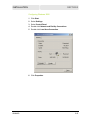
Configuring Windows 2000
WA840G
1
Click Start.
2
Select Settings.
3
Select Control Panel.
4
Double-click Network and Dial-Up Connections.
5
Double-click Local Area Connection.
6
Click Properties.
2-13
SECTION 2
2-14
INSTALLATION
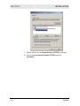
7
Ensure the box next to Internet Protocol (TCP/IP) is selected.
8
Click to highlight Internet Protocol (TCP/IP) and click
Properties.
WA840G
INSTALLATION
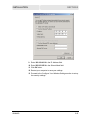
SECTION 2
9
Enter 192.168.40.10 in the IP Address field.
10 Enter 255.255.255.0 in the Subnet Mask field.
11 Click OK twice.
12 Restart your computer to save your settings.
13 Proceed to the Configure Your Wireless Settings section to set up
the security settings.
WA840G
2-15
SECTION 2
INSTALLATION
Configuring Windows XP
This configuration assumes you have retained the default interface
for Windows XP. If you are running the ‘Classic’ interface, please
follow the instructions for Windows 2000.
2-16
1
Click Start.
2
Select Settings.
3
Select Control Panel.
4
Double-click Network and Dial-Up Connections.
5
Double-click Local Area Connection. The Local Area
Connection Status window appears:
6
Click Properties.
WA840G
INSTALLATION
SECTION 2
7
WA840G
Ensure the box next to Internet Protocol (TCP/IP) is selected.
2-17
SECTION 2
INSTALLATION
8
Click to highlight Internet Protocol (TCP/IP) and click
Properties.
9
Enter 192.168.40.10 in the IP Address field.
10 Enter 255.255.255.0 in the Subnet Mask field.
11 Click OK twice.
12 Restart your computer to save your settings.
13 Proceed to the Configure Your Wireless Settings section to set up
the security settings.
2-18
WA840G
INSTALLATION
SECTION 2
Configure Your Wireless Security Settings
Before your access point can communicate securely with your
computer, you must configure your wireless security settings. Failure
to configure these settings properly could compromise your network
to wireless hackers.
Logging In
WARNING!
When first configuring your access point, it is
recommended that you use an Ethernet cable. Performing
the INITIAL configuration using a wireless connection is
not secure and is not recommended.
After you have finished the initial configuration of the
access point, your connection will be secure and you can
safely use either a wired or wireless connection.
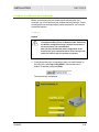
1
Once the access point is connected, open your web browser. In
the URL field, enter http://192.168.40.1 (the access point’s
default IP address) and press Enter.
The login screen is displayed:
WA840G
2-19
SECTION 2
INSTALLATION
2
Enter the User ID. The default factory setting is admin.
3
Enter the Password. The default factory setting is motorola.
Once you have logged in, for security reasons, you should change the User ID
and Password. See Wireless Security Setup.
4
Click Log In to enter the access point’s Web-based Configuration
Utility.
Wireless Security Setup
To set up the correct security protocols for your access point:
1
Select Control Panel > Device Security.
2
In the Change User ID field, enter in your User ID. Create an ID
that contains multiple case-sensitive characters as well as
numbers. It cannot be longer than 64 characters.
3
In the Change User Password field, enter your Login Password.
Create a password that contains multiple case-sensitive
characters as well as numbers and symbols like “_ + )”. It cannot
be longer than 64 characters.
4
Re-enter your Password.
5
Click Apply.
6
Once the settings have been accepted, click Restart and log
back into the Configuration Utility using your new User ID and
Password.
7
Select to Wireless > Basic.
8
Change the SSID to a user-friendly name and click Apply.
9
Navigate to Wireless > Security.
10 Select WPA-PSK from the ESS Authentication options.
11 Select TKIP from Encryption Status options.
12 Enter a new Pass Phrase in the Pass Phrase field. The Pass
Phrase must be between 8 and 63 characters.
13 Enter your Pass Phrase again in the Pass Phrase Confirm field.
Remember this Pass Phrase so that you can enter the same
phrase for the Motorola client devices on your wireless LAN.
14 Click Apply and then click Restart. Your wireless security
configuration is now complete.
2-20
WA840G
Section 3:Configuration
Use the information in this section to modify the access point’s
settings. For example you can customize features for your home
network, change settings such as your user name or password, or
view the status of the network.
The screenshots seen here are intended for reference only; your
version of firmware may differ slightly.
Using the Web-Based Configuration Utility
Logging In
1
Once the access point is connected, open your web browser. In
the URL field, enter http://192.168.40.1 (the access point’s
default IP address) and press the Enter key.
The login screen appears.
WA840G
3-1
SECTION 3
CONFIGURATION
2
Enter the User ID. The default factory setting is admin.
3
Enter the Password. The default factory setting is motorola.
After you have logged in, for security reasons you should change
the User ID and Password. See below.
4
Click Log In to enter the access point’s Configuration Utility.
Navigation
Each of the following subsections describe the components of the
access point’s Configuration Utility, which is accessible from a web
browser. These sections include:
To navigate, click on a major section and then the associated
subsection. For example, to adjust the User Login ID, click
CONTROL PANEL on the left, then DEVICE SECURITY tab at top
on the right. The Web-based Configuration Utility uses Javascript.
Your web browser’s Javascript needs to be enabled.
Help, Restart, and Logout
Click on the appropriate command to execute the action.
Help
Accesses Help.
Restart
Restarts your session with the Configuration Utility. When
Restart flashes, the change you have made requires that
you restart the unit.
For convenience, it is recommended that you finish
all of your configuration changes and then restart the
unit.
Logout
3-2
Logs out of the access point’s Configuration Utility.
WA840G
CONFIGURATION
SECTION 3
Configuring Wireless Network Settings
The Wireless Network screens allow you to adjust settings for your
wireless connection:
!
Basic
!
Security
!
Site Monitor
!
Advanced
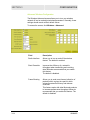
Basic Wireless Configuration
The Wireless – Basic screen allows you to set up your Service Set
Identifier (SSID) parameters for your network. The SSID is the name
of your network that is shared among all the devices in a wireless
network.
Although your access point has a default SSID, it is recommended
that you change it to a name that is easy for you to remember.
To access the screen, click Wireless > Basic.
WA840G
Field or Button
Description
Network Name
(SSID)
Enter a name of no more than 32 alphanumeric
characters. This SSID must be entered on
every wireless device on your wireless network
to communicate back to the router. The default
SSID is motorola XXX, where XXX are the last
3 characters of your Wireless MAC address,
found on the label on the bottom of the unit.
3-3
SECTION 3
CONFIGURATION
Field or Button
Description
Channel Number
Identifies the channel on which the access point
communicates. Each wireless client must use
the same channel to enable communication. If
changed wirelessly, once you restart the access
point, you will lose your wireless connection.
Change the wireless device’s channel to the
new channel to log back into the access point.
The default is Channel 11.
Operation Mode
Enables you to select the type of transmission
protocol your wireless network uses.
The options are:
!
!
!
3-4
Compatibility (802.11b/g) – default setting
Performance (802.11g only)
Legacy (802.11b only)
Wireless MAC
Address
Displays the MAC address of the unit.
Apply
Click to save your settings.
Cancel
Click to cancel any changes.
WA840G
CONFIGURATION
SECTION 3
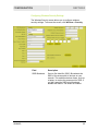
Configuring Wireless Security Settings
The Wireless Security screen allows you to configure wireless
security settings. To access the screen, click Wireless > Security.
WA840G
Field
Description
SSID Broadcast
Service Set Identifier (SSID). Broadcasts the
SSID of the access point to devices on your
network. This enables wireless clients, such as
a laptop, to receive the access point’s SSID. If
you don’t want the SSID to be broadcast,
disable this feature. The default is enabled.
3-5
SECTION 3
CONFIGURATION
Field
Description
ESS
Authentication
Extended Service Set (ESS). Authentication
establishes either an open or secure
verification of communication with an access
point. This setting does not encrypt your
wireless transmission.
The options are:
Open
System
No authentication is used.
Default setting.
Pre-Shared
Key (PSK)
The Pre-Shared Key (PSK)
authentication method is
used.
WPA
Wi-Fi® Protected Access
(WPA) authentication
(802.1X) is used with an EAP
type.
WPA-PSK
WPA authentication (802.1X)
is used with a pre-shared
key.
WPA-PSK is recommended for home users not
using a RADIUS server.
3-6
WA840G
CONFIGURATION
SECTION 3
Field
Description
Encryption Status
Determines the type of security encryption
algorithms used for the Key. This security
setting encrypts your wireless transmission.
None, WEP64, and WEP128 are available
only when Open System or Pre-Shared
KEY (PSK) is selected in the ESS
Authentication field.
! TKIP and AES are available only when
WPA and WPA-PSK are selected in the
ESS Authentication field.
The options are:
!
None
No security. Default setting.
WEP64
Wired Equivalent Privacy - 64-bit
strength (provides 4 Keys)
WEP128
Wired Equivalent Privacy 128-bit strength (provides 2
Keys)
TKIP
Temporal Key Integrity Protocol
AES
Advanced Encryption Standard
TKIP is recommended for home users. If
available, AES provides stronger encryption.
802.1X mode
Can only be enabled when the ESS
Authorization is set to Open or PSK and either
WEP64 or WEP128 is selected (see the
Encryption Status field). During the
Authentication process, the server verifies the
identity of the client attempting to connect to
the network. When WPA-PSK is selected in the
ESS Authentication field, this option is
automatically selected.
If not already enabled, select to activate this
feature. When enabled, Dynamic Key
generation occurs, meaning a key is
automatically generated when the client
requests one.
WA840G
3-7
SECTION 3
CONFIGURATION
Field
Description
Key Input Method
Available if PSK and/or WEP is selected. The
options are:
! Pass Phrase – default setting
! Hexadecimal
! ASCII
If you select either Pass Phrase or
Hexadecimal, in Key Content, the format of the
Key appears in a hexadecimal format.
If you are using other non-Motorola wireless
products and a security algorithm other than
WPA-PSK, you must enter your WEP keys
manually in either ASCII or hexadecimal format
for the non-Motorola wireless products.
Pass Phrase
Enter the Pass Phrase to be used for Key
encryption. Keep a record of this Pass Phrase
so you can enter the same phrase for the
Motorola client devices on your wireless LAN.
You will use this Pass Phrase when using WPA
security with your client devices. Pass Phrase
must be between 8 and 63 characters.
The default pass phrase is motorola.
Key Length
The option selected determines the strength of
the key. This field is only available when ESS
Authentication is set PSK and the Encryption
Status is set to None.
There are two options:
!
!
3-8
128-bit
64-bit.
WA840G
CONFIGURATION
SECTION 3
Field
Description
Key Index
Use the drop-down list here to select one of the
Key Content fields below (Key 1, Key 2, etc). A
maximum of four different Keys (1, 2, 3, or 4)
are available, the number of keys is determined
by what is selected in the ESS Authentication
and Encryption Status field.
The Key selected here must match the Key in
the client. For example, if you select Key 1 here
you have to select Key 1 for the client.
The default is 1.
Key Content
Key 1
Key 2
Key 3
Key 4
Enter Key content in these fields. The Key
Content format is selected in the Key Input
Method field.
For the key content, the phrase is
auto-generated by the password entered in the
Pass Phrase field. For non-Motorola clients,
you will use these Keys (and not Pass Phrase)
when using WEP for security. The Key will not
automatically fill in until you have clicked
Apply.
If you have selected Hexadecimal or ASCII
formatting (in the Key Input Method field), you
can then enter your own Hexadecimal or ASCII
keys. To enter keys manually, you must have
WEP64 or WEP128 selected in the Encryption
Status field.
For WEP64 keys, 5 case sensitive ASCII
characters are allowed or 10 hexadecimal
characters (using only characters 0-9 and
A-F)
! For WEP128 keys, 13 case sensitive ASCII
characters are allowed or 26 hexadecimal
characters (using only characters 0-9 and
A-F)
If entering a key manually, don’t leave a key
field blank or enter all 0’s. These are not secure
keys.
!
WA840G
3-9
SECTION 3
CONFIGURATION
Field
Description
Group Key
Renewal Interval
This is the number of seconds that pass until
your access point sends out a new group key
and is only available if WPA or 802.1X are
selected.
The default is 300 seconds.
RADIUS Server
IP
Enter the RADIUS Server IP and Port number.
RADIUS is an authentication and accounting
system to verify users.
RADIUS Server
Port Number
To display these fields, either of the following
conditions need to exist:
Open System is selected, along with either
WEP64 or WEP128, and 802.1X is enabled
! WPA is selected and TKIP or AES is
selected.
The default RADIUS Port Number is 1812.
!
RADIUS Shared
Secret
Type and re-type the RADIUS password in
these fields.
RADIUS Shared
Secret
Confirmation
3-10
WA840G
CONFIGURATION
SECTION 3
Field
Description
Wireless MAC
Access Control
List
Enables you to control which device accesses
your wireless network based upon their MAC
address. The default is disabled. The options
are:
Enable
Select to enable/disable the MAC
Access Control List (ACL). When
disabled, the MAC ACL is not
active and any wireless station is
allowed to communicate with the
wireless access point.
Allow
Allows only the wireless devices in
the ACL to communicate with the
wireless access point.
Deny
Denies wireless devices in the ACL
from communicating with the
wireless access point.
To add a MAC address to the ACL:
1
2
Check enable.
Select Allow or Deny from the drop-down
list.
3 Enter a MAC Address or use one of the
Learned MAC Addresses. To use one of
the Learned MAC addresses, click the
address number. The number automatically
appears in the Wireless MAC Address
Control List.
To alter a MAC address, remove and
replace with the updated address.
4 Click Add to enter the address into the
ACL.
5 Click Apply to save.
To delete a MAC address from the ACL:
1
2
3
WA840G
Click the MAC address you wish to delete.
Once activated, the field will change color.
Click REMOVE to clear the address.
Click APPLY to save.
3-11
SECTION 3
CONFIGURATION
Field
Description
Learned MAC
Addresses
Displays the MAC addresses (wireless devices
only) the access point has already recorded.
Apply
If you wish to use one of the displayed MAC
addresses, click the address number. The
number automatically appears in the
Wireless MAC Address Control List.
! Click Refresh to search for additional MAC
addresses.
Click to save your settings.
Cancel
Click to cancel any changes.
!
Monitoring Wireless Access Points
The Site Monitor screen displays information about wireless access
points and stations:
Station
Association
List
Identifies only those stations that are connected
to your wireless access point.
Site Survey
Displays information about other access points
in the area.
To access the screen, click Wireless > Site Monitor.
3-12
WA840G
CONFIGURATION
Field
SECTION 3
Description
Station Association List
Refresh
Click to refresh the Station Association List.
MAC Address
Displays the MAC address of clients found on
the LAN.
Host Name
Displays the name of the device attached.
Site Survey
WA840G
Scan
Click to search for more access points or
clients.
SSID
Displays the SSID of the device found.
MAC Address
Displays the MAC address of the device found.
Channel
Displays the channel upon which the device is
broadcasting.
Signal Strength
Displays the Signal Strength of the device
found.
Wireless Mode
Displays which protocol is used, 802.11b or
802.11g.
Security
Displays the security protocol used.
3-13
SECTION 3
CONFIGURATION
Advanced Wireless Configuration
The Wireless-Advanced screen allows you to turn your wireless
network off and on and adjust wireless parameters. Generally, these
settings should remain at their default values.
To access the screen, click Wireless > Advanced.
Field
Description
Radio Interface
Allows you to turn on and off the wireless
feature. The default is enabled.
Short Preamble
Improves the efficiency of a network's
throughput when transmitting and receiving
data. Motorola recommends that you enable
this feature.
The default is disabled.
Frame Bursting
Allows you to send more frames (collection of
packets) within a given time period, which
enhances network efficiency and reduces
overhead.
This feature works with other Motorola products
to increase performance throughput. Motorola
recommends that you enable this feature. The
default is disabled.
3-14
WA840G
CONFIGURATION
SECTION 3
Field
Description
RTS Threshold
Allows you to modify the RTS threshold, which
is the packet size at which an access point
issues a request to send (RTS). The range is 0
to 2347 bytes.
The default is 2347.
Fragmentation
Threshold
Allows you to set the size at which packets are
fragmented and transmitted a piece at a time
instead of all at once. The setting must be
within the range of 256 to 2346 bytes.
The default is 2346.
Beacon Period
Allows you to set the time units for the beacon
period. A beacon is a packet broadcast by the
access point to keep the network synchronized.
You are able to set the Beacon Period value
from 1 to 65535 in Time Units (TU). The default
is 100.
Since changes to the Beacon Period and
Delivery Traffic Indicator Maps (DTIM) settings
may affect wireless performance, it is best to
use the default settings.
DTIM Period
Allows you to set the Delivery Traffic Indicator
Maps (DTIM) period value from 1 to 255 in
multiples of Beacon Periods. The default is 3.
Since changes to the Beacon Period and
Delivery Traffic Indicator Maps (DTIM) settings
may affect wireless performance, it is best to
use the default settings.
WA840G
3-15
SECTION 3
CONFIGURATION
Field
Description
Basic Rate Set
Allows you to set the transmission rate. The
access point broadcasts different transmission
rates so clients know which transmission rate to
use to join the network.
The options are:
11g Protection
Mode
1 to 2
Mbps
The slowest speed available.
Default
Ensures compatibility with
802.11b or 802.11g devices
All
Ensures compatibility with all
devices.
Ensures that your wireless access point does
not interfere with neighbor networks. 802.11g
networks cause collisions on 802.11b networks,
so the Protection Mode forces the 802.11g
network to negotiate around the 802.11b
network.
The options are:
WDS Mode
Disable
802.11g Protection Mode is
never used.
Auto
802.11g Protection Mode is used
if either an 802.11b client joins
the network or the access point
detects an 802.11b network on
the same channel. Default
setting.
Enables WDS mode, which allows you to share
and expand your network with other wireless
access points. The WDS fields, WDS Restrict
Mode and WDS Restrict MAC address become
active once WDS is enabled.
Set up the access point’s with the same
Wireless SSID and security settings.
When WDS mode is enabled, any access point,
if configured to your access point’s settings, can
connect to your network. The default is
disabled.
3-16
WA840G
CONFIGURATION
SECTION 3
Field
Description
WDS Restrict
Mode
Protects your network by assigning access to
only the access points you designate. Assign
the access points’ MAC addresses in the WDS
Restrict MAC Addresses fields.
The default is enabled.
WDS Restrict
MAC Addresses
To activate these fields, WDS Restrict Mode
must be enabled.
!
!
!
Enter up to four wireless MAC addresses
To edit an entry, highlight the number and
change
To delete a number, delete each field
Apply
Click to save your settings.
Cancel
Click to cancel any changes.
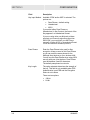
Configuring Control Panel Settings
The Control Panel screens enable administrative maintenance for
your access point, such as changing your login User ID/Password,
updating your firmware, or backing up your configuration.
The following screens are available in Control Panel:
WA840G
!
Network Address
!
Device Security
!
Firmware Update
!
Configuration Data
3-17
SECTION 3
CONFIGURATION
Configuring Network Address
This screen allows you to change your Connection Mode and IP
settings.
To access the screen, click Control Panel > Network Access.
Field
Description
LAN Ethernet
MAC Address
Displays the unit’s Ethernet MAC address.
Connection Mode
The access point supports two connection
modes for acquiring its own IP configuration
settings:
! DHCP
! Static Assigned
Select the appropriate connection mode for
your network.
Connection
Status
Provides current information about the
connection status of the access point.
IP Address
Displays the access point’s IP Address used to
connect to your network.
If DHCP is selected, this is the IP Address that
your access point is currently using to access
the Internet. If using Static Assigned, enter the
IP Address here.
3-18
WA840G
CONFIGURATION
SECTION 3
Field
Description
Subnet Mask
Displays the access point’s Subnet Mask
address used to connect to your network.
If DHCP is selected, this is the Subnet Mask
Address that your access point is currently
using to access the Internet. If using Static
Assigned, enter the Subnet Mask Address here.
Gateway IP
Displays the access point’s Gateway IP
Address used to connect to your network.
If DHCP is selected, this is the Gateway IP
Address that your access point is currently
using to access the Internet. If using Static
Assigned, enter the Gateway IP Address here.
Apply
Click to save your settings.
Cancel
Click to cancel any changes.
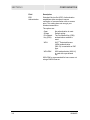
Configuring Device Security
This screen allows you to change your User ID and Password and
adjust the inactivity time.
To access the screen, click Control Panel > Device Security.
WA840G
Field
Description
Login User ID
Changes the User ID used for logging into
the access point’s Configuration Utility. It
cannot be longer than 63 bytes. A blank user
name is not allowed. The default is admin.
3-19
SECTION 3
CONFIGURATION
Field
Description
Login Password
Use this option to change the Password used
to log into the access point’s web based
utility. It cannot be longer than 63 bytes. A
blank password is not allowed. The default is
motorola.
Login Password
Confirm
Login Idle Time
Sets the amount of idle time (no actions
occur) that elapses before the access point
automatically logs you off. The default is 10
minutes.
Apply
Click to save your settings.
Cancel
Click to cancel any changes.
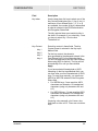
Updating Firmware
The Firmware Update screen allows you to update your access
point’s firmware, the mechanism that controls your access points
hardware.
To check for a firmware update, access this website
www.motorola.com/broadband/networking.
To update the firmware:
3-20
1
Download the latest firmware file to your computer from the
Motorola website.
2
Click Control Panel > Firmware Update to access the Firmware
Update screen.
3
To locate the file you downloaded, type the path to the file or click
Browse and navigate to it.
4
Click UPDATE to update the access point with the selected
firmware file. The access point will inform you that you
successfully updated the unit.
5
Follow the prompts to restart.
WA840G
CONFIGURATION
SECTION 3
Saving and Restoring Configuration Settings
The Configuration Data screen allows you to save and restore your
access point’s configuration settings. You are also able to reset the
access point to its factory default settings.
To access the screen, click Control Panel > Configuration Data.
To reset the access point to its original configuration; click FACTORY
DEFAULTS.
To backup your settings:
1 Click BACKUP.
2
From the pop up window, choose the destination for the file.
3
Enter a descriptive file name.
To restore your settings:
1 Locate the Configuration file on your computer by entering the
path to the file or click Browse and navigate to it.
2
WA840G
Click RESTORE to reapply the saved settings with the selected
file.
3-21
Section 4:Troubleshooting
This section details possible solutions to common problems that may
occur in using the access point.
Contact
If you are unable to locate a solution here, please access our website
at www.motorola.com/broadband/networking for the latest information.
You can also reach us 7 days a week, 24 hours a day at
1-877-466-8646.
Hardware Solutions
My computer is experiencing difficulty connecting to the wireless
network.
WA840G
!
Ensure that your access point is powered on and that the
Wireless LED is lit.
!
Ensure that your wireless adapter (PCI card, Notebook or
Ethernet adapter) is installed correctly and is active.
!
Ensure that your wireless adapter’s radio signal is enabled.
Review your adapter’s documentation for further instructions.
!
Ensure that your wireless adapter for your PC and the access
point have the same security settings that will allow your
computer to access the wireless network. For details on adjusting
your security settings, see Wireless Security Settings in
Section 3: Configuration.
!
Ensure that your access point is within range of your router or is
not behind an obstruction. For example, metal structures will
interfere with the signal, as will 2.4 GHz cordless phones, and
microwaves.
!
Ensure that your antenna is connected and that your router’s
antenna is also connected.
4-1
SECTION 4
TROUBLESHOOTING
My computer is experiencing difficulty in connecting to the access
point.
!
Ensure that all of your cable connections are firmly connected.
This includes the cables from the wall to your modem, between
the router and modem, and, if available, from the access point to
your PC.
!
Ensure that your LEDs are not lit Red or not at all. For further
information about LED descriptions, see Section 1: Overview.
!
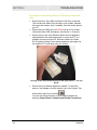
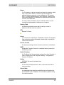
Ensure that you are using Ethernet cables and not telephone
cables between the router and modem or router and PC, or if
available, access point and PC. Ethernet cables use a wider
RJ-45 style plug using 8 wires where telephone style plugs use
the smaller RJ-11 style plug using 4 to 6 wires.
The plug on the left is RJ-45; the plug on the right is RJ-11 – use only
RJ-45.
!
Ensure that your Ethernet adapter is enabled. To check the
status of your adapter, click the monitor icon in the System Tray
at the bottom right of your screen.
You can also check the status of your Ethernet adaptor by
selecting Control Panel > Network and Dial-Up Connections.
4-2
WA840G
TROUBLESHOOTING
SECTION 4
Software Solutions
I would like to see if my Internet connection is live.
Use the ping command to test the connection. Before attempting,
ensure that Obtain an IP address automatically has been selected
in the computer’s settings and that you have an IP address assigned.
Refer to Configure Your Computers in Section 2: Configuration, for
further details.
1
Open a command prompt by clicking Start and Run.
2
For Windows 98 and ME, in the Open field, type command and
press Enter or OK.
For Windows 2000 and XP, type cmd. Or, navigate using your
Start button to Programs>Accessories>Command Prompt.
3
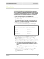
In the Command window, type ipconfig.
!
You should see an IP address for your network adapter:
Ethernet Adapter Local Area Connection:
Connection-specific DNS Suffix.: Example.example.example.com.
IP Address. . . . . . . . . . . . : 192.168.40.10
Subnet Mask . . . . . . . . . . . : 255.255.255.0
Default Gateway . . . . . . . . . : 192.168.40.1
4
In the Command window, type ping followed by the access
point’s IP address and press Enter. For example type:
ping 192.168.40.10.
There is a good possibility that the Default Gateway’s IP address
is the access point’s IP address. You can verify the access point’s
IP address on the Control Panel > Network Access screen.
5
WA840G
!
If you receive a reply (the first word will be Reply…), then
your computer is connected to the access point. Proceed to
Step 5.
!
If you do NOT receive a reply, repeat steps 1 – 4 on a
different computer to verify that the first computer is not the
cause of the problem.
In the Command window, type ping followed by your ISP’s
default gateway and press Enter. For example type:
ping 216.109.125.72.
4-3
SECTION 4
TROUBLESHOOTING
!
If you receive a reply (For example: Reply from
216.109.125.72…), then your connection to the Internet is
live.
You can verify the ISP’s IP address at the Gateway IP field on
the Control Panel > Network Access screen.
!
6
If you do NOT receive a reply, repeat steps 1 – 5 on a
different computer to verify that the first computer is not the
cause of the problem.
If you cannot determine your ISP’s default gateway, ping
www.yahoo.com or another known web location.
I cannot access the Configuration Utility for the access point.
4-4
!
Verify your Ethernet connection to the access point.
!
Verify that the IP address of the PC being used to configure the
access point is on the same network as the access point’s
configuration IP address.
!
The IP address of your network adapter must be on the same
network and not a duplicate of any others on the network (for
example: 192.168.40.10 and using a subnet mask of
255.255.255.0 can be used to login to the access point’s default
IP address of 192.168.40.1). To adjust the IP address for your
PC, refer to Configure Your Computers in
Section 2: Configuration.
!
Verify that you can ping the access point on this IP address.
!
In the Command window, type ping and your access point’s
default IP address and press Enter. For example type:
ping 192.168.40.1
!
If you have changed the factory configured default IP address
of the access point, you will need to set your network adapter
accordingly.
!
Verify you are entering the correct URL in the browser. The
default is http://192.168.40.1. If you think you have changed the
IP address used to configure the access point and cannot
remember it, you must reset the unit back to factory defaults. To
do this, press and hold the reset button for more the 5 seconds.
This clears the access point’s user settings, including User ID,
Password, IP Address, and Subnet mask.
!
After the access point is reset to factory default, re-verify the
Ethernet connectivity and IP address issues.
!
Verify you are using the latest version of IE or Netscape. IE 5.2
and below are not supported.
WA840G
TROUBLESHOOTING
SECTION 4
What if Pass Phrase isn’t supported? What do I enter for my
security?
Some wireless cards do not support Pass Phrase or Motorola’s Pass
Phrase algorithm, which means you have to enter the entire Key
Content found in the appropriate Key field.
So, using the WEP example from above if using Key 1, you would
enter 03F32226A…etc. into the Network Key field of the example
Network Adapter, seen below. Ensure that the Key index matches
what is selected on the wireless network.
WA840G
4-5
SECTION 4
TROUBLESHOOTING
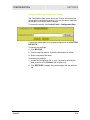
I cannot browse past the first screen of the Configuration Utility.
Sometimes, especially when upgrading, some leftover files may be in
your Internet Cache. Flush your cache and restart your unit to fix:
From Internet Explorer’s menu, select Tools > Options and click
Delete Files to clear you cache.
4-6
WA840G
Section 5:Glossary
A
Access Point (AP)
A device that provides wireless LAN connectivity to wireless
clients (stations).
Adapter
A device or card that connects a computer, printer, or other
peripheral device to the network or to some other device. A
wireless adapter connects a computer to the wireless LAN.
Address translation
See NAT.
Ad-Hoc Network
A temporary local area network connecting AP clients together,
usually just for the duration of the communication session. The
clients communicate directly to each other and not through an
established, such as through a router. Also known as: IBSS
(Independent Basic Service Set).
ASCII
The American Standard Code for Information Interchange refers
to alphanumeric data for processing and communication
compatibility among various devices; normally used for
asynchronous transmission.
B
Bandwidth
The transmission capacity of a medium in terms of a range of
frequencies. Greater bandwidth indicates the ability to transmit
more data over a given period of time.
bps
Bits Per Second
Broadband
A communications medium that can transmit a relatively large
amount of data in a given time period.
WA840G
5-1
SECTION 5
GLOSSARY
BSS
Basic Service Set. A configuration of Access Points that
communicate with each other without resorting any infrastructure.
Also known as Ad-Hoc networks. Also see ESS.
C
Client
In a client/server architecture, a client is a computer that requests
files or services such as file transfer, remote login, or printing
from the server. On an IEEE 802.11b/g wireless LAN, a client is
any host that can communicate with the access point. Also called
a CPE. A wireless client is also called a “station.” Also see server.
Coaxial Cable
A type of cable consisting of a center wire surrounded by
insulation and a grounded shield of braided wire. The shield
minimizes electrical and radio frequency interference. Coaxial
cable has high bandwidth and can support transmission over long
distances.
CPE
Customer Premise Equipment: typically computers, printers, etc,
that are connected to the gateway at the subscriber location. CPE
can be provided by the subscriber or the cable service provider.
Also called a client.
Crossover Cable
A crossover cable is a cable that is used to interconnect two
computers by "crossing over" (reversing) their respective pin
contacts. A crossover cable is sometimes known as a null
modem.
D
Default Gateway
A routing device that forwards traffic not destined to a station
within the local subnet.
DHCP
A Dynamic Host Configuration Protocol server dynamically
assigns IP addresses to client hosts on an IP network. DHCP
eliminates the need to manually assign static IP addresses by
“leasing” an IP address and subnet mask to each client. It
enables the automatic reuse of unused IP addresses.
DMZ
DeMilitarized Zone. This service opens one IP address to the
Internet, usually for online gaming, and acts as a buffer between
the Internet and your network.
5-2
WA840G
GLOSSARY
SECTION 5
DNS
The Domain Name System is the Internet system for converting
domain names (like www.motorola.com) to IP addresses. A DNS
server contains a table matching domain names such as
Internetname.com to IP addresses such as 192.169.9.1. When
you access the world-wide web, a DNS server translates the URL
displayed on the browser to the destination website IP address.
The DNS lookup table is a distributed Internet database; no one
DNS server lists all domain name to IP address matches.
Domain Name
A unique name, such as motorola.com, that maps to an IP
address. Domain names are typically much easier to remember
than are IP addresses. See DNS.
Download
To copy a file from one computer to another. You can use the
Internet to download files from a server to a computer.
Driver
Software that enables a computer to interact with a network or
other device. For example, there are drivers for printers, monitors,
graphics adapters, modems, Ethernet, USB, HPNA, and many
others.
DSL
Digital Subscriber Line
DSSS
Direct-Sequence Spread Spectrum. DSSS is a transmission
technology used in WLAN transmissions where a data signal at
the sending station is combined with a higher data rate bit
sequence, or chipping code, that divides the user data according
to a spreading ratio. The chipping code is a redundant bit pattern
for each bit that is transmitted, which increases the signal's
resistance to interference. If one or more bits in the pattern are
damaged during transmission, the original data can be recovered
due to the redundancy of the transmission.
Dynamic IP Address
An IP address that is temporarily leased to a host by a DHCP
server. The opposite of Static IP Address.
WA840G
5-3
SECTION 5
GLOSSARY
E
ESS
An Extended Service Set (ESS) is a set of two or more BSSs that
form a single subnetwork. See also BSS.
Ethernet
The most widely used LAN type, also known as IEEE 802.3. The
most common Ethernet networks are 10Base-T, which provide
transmission speeds up to 10 Mbps, usually over unshielded,
twisted-pair wire terminated with RJ-45 connectors. Fast Ethernet
(100Base-T) provides speeds up to 100 Mbps. “Base” means
“baseband technology” and “T” means “twisted pair cable.”’
Each Ethernet port has a physical address called the MAC
address. Also see MAC address.
Event
A message generated by a device to inform an operator or the
network management system that something has occurred.
F
Firmware
Code written onto read-only memory (ROM) or programmable
read-only memory (PROM). Once firmware has been written onto
the ROM or PROM, it is retained even when the device is turned
off. Firmware is upgradeable.
FTP
File Transfer Protocol is a standard Internet protocol for
exchanging files between computers. FTP is commonly used to
download programs and other files to a computer from web pages
on Internet servers.
G
Gateway
A device that enables communication between networks using
different protocols. See also router.
GUI
Graphical User Interface
5-4
WA840G
GLOSSARY
SECTION 5
H
Hexadecimal
A base-sixteen numbering system that uses sixteen sequential
numbers (0 to 9 and the letters A to F) as base units before
adding a new position. On computers, hexadecimal is a
convenient way to express binary numbers.
Host
In IP, a host is any computer supporting end-user applications or
services with full two-way network access. Each host has a
unique host number that combined with the network number
forms its IP address.
Host also can mean:
!
A computer running a web server that serves pages for one or
more web sites belonging to organization(s) or individuals
!
A company that provides this service
!
In IBM environments, a mainframe computer
I
ICMP
Internet Control Message Protocol is a protocol used for error,
problem, and informational messages sent between IP hosts and
gateways. ICMP messages are processed by the IP software and
are not usually apparent to the end-user.
IEEE
The Institute of Electrical and Electronics Engineers, Inc.
(http://www.ieee.org) is an organization that produces standards,
technical papers, and symposiums for the electrical and
electronic industries and is accredited by ANSI. 802.11b and
802.11g are examples of standards they have produced.
Internet
A worldwide collection of interconnected networks using TCP/IP.
IP
Internet Protocol is a set of standards that enable different types
of computers to communicate with one another and exchange
data through the Internet. IP provides the appearance of a single,
seamless communication system and makes the Internet a virtual
network.
WA840G
5-5
SECTION 5
GLOSSARY
IP Address
A unique 32-bit value that identifies each host on a TCP/IP
network. TCP/IP networks route messages based on the
destination IP address.
For a Class C network, the first 24 bits are the network address
and the final 8 bits are the host address; in dotted-decimal format
it appears “network.network.network.host.”
ISDN
Integrated Services Digital Network
ISP
Internet Service Provider
L
LAN
Local Area Network. A local area network provides a full-time,
high-bandwidth connection over a limited area such as a home,
building, or campus. Ethernet is the most widely used LAN
standard.
M
MAC Address
The Media Access Control address is a unique, 48-bit value
permanently saved in the ROM at the factory to identify each
Ethernet network device. It is expressed as a sequence of 12
hexadecimal digits printed on the unit’s label. You need to
provide the MAC Address to the cable service provider. Also
called an Ethernet address, physical address, hardware address,
or NIC address.
MB
One megabyte; equals 1,024 x 1,024 bytes, 1,024 kilobytes, or
about 64 million bits.
Mbps
Million bits per second (megabits per second). A rate of data
transfer.
MTU
The Maximum Transmission Unit is the largest amount of data
that can be transmitted in one discrete message on a given
physical network. The MTU places an upper bound on the size of
a message that can be transferred by the network in a single
frame. Messages exceeding the MTU must be fragmented before
transmission, and reassembled at the destination.
5-6
WA840G
GLOSSARY
SECTION 5
Multicast
A data transmission sent from one sender to multiple receivers.
See also broadcast and unicast.
N
NAT
Network Address Translation is an Internet standard for a LAN to
use one set of IP addresses for internal traffic and a second set
of IP addresses for external traffic. NAT provides some security
because the IP addresses of LAN computers are invisible on the
Internet.
Network
Two or more computers connected to communicate with each
other. Networks have traditionally been connected using some
kind of wiring.
NIC
A Network Interface Card converts computer data to serial data in
a packet format that it sends over the LAN. A NIC is installed in
an expansion slot or can be built-in. Every Ethernet NIC has a
MAC address permanently saved in its ROM.
P
Packet
The unit of data that is routed between the sender and
destination on the Internet or other packet-switched network.
PCMCIA
The Personal Computer Memory Card International Association
sets international standards for connecting peripherals to portable
computers. Laptop computers typically have a PCMCIA slot that
can hold one or two PC Cards to provide features such as
Ethernet connectivity.
PING
A network utility that tests host reachability by sending a small
packet to the host and waiting for a reply. If you PING a computer
IP address and receive a reply, you know the computer is
reachable over the network. It also stands for “Packet InterNet
Groper.”
Port Triggering
A mechanism that allows incoming communication with specified
applications.
WA840G
5-7
SECTION 5
GLOSSARY
PPP
Point-to-Point Protocol is used to transport other protocols,
typically for simple links over serial lines. It is most commonly
used to access the Internet with a dial-up modem.
PPPoE
Point-to-Point Protocol over Ethernet. Used by many DSL Internet
Service Providers for broadband connection.
PPTP
Point-to-Point Tunneling Protocol encapsulates other protocols. It
is a new technology to create VPNs developed jointly by several
vendors.
Private IP Address
An IP address assigned to a computer on a LAN by the DHCP
server for a specified lease time. Private IP addresses are
invisible to devices on the Internet. See also Public IP Address.
Protocol
A formal set of rules and conventions for exchanging data.
Different computer types (for example PC, UNIX, or mainframe)
can communicate if they support common protocols.
Public IP Address
The IP address assigned to the router or AP by the service
provider. A public IP address is visible to devices on the Internet.
See also Private IP Address.
R
RJ-11
The most common type of connector for household or office
phones.
RJ-45
An 8-pin modular connector; the most common connector type for
10Base-T or 100Base-T Ethernet networks.
Roaming
The ability to transfer your wireless session from one AP to
another AP seamlessly.
ROM
Read-Only Memory.
5-8
WA840G
GLOSSARY
SECTION 5
Router
On IP networks, a device connecting at least two networks, which
may or may not be similar. A router is typically located at a
gateway between networks. A router operates on OSI network
layer 3. It filters packets based on the IP address, examining the
source and destination IP addresses to determine the best route
on which to forward them.
A router is often included as part of a network switch. A router
can also be implemented as software on a computer.
Routing Table
A table listing available routes that is used by a router to
determine the best route for a packet.
RTS
Request To Send.
S
Server
In a client/server architecture, a dedicated computer that supplies
files or services such as file transfer, remote login, or printing to
clients. Also see client.
Service Provider
A company providing Internet connection services to subscribers.
SMTP
Simple Mail Transfer Protocol is a standard Internet protocol for
transferring e-mail.
Static IP Address
An IP address that is permanently assigned to a host. Normally, a
static IP address must be assigned manually. The opposite of
Dynamic IP Address.
Station
IEEE 802.11b term for wireless client.
Subscriber
A user who accesses television, data, or other services from a
service provider.
Subnet Mask
A methodology that determines what the router will examine for
the destination of an IP address. A router delivers packets using
the network address.
WA840G
5-9
SECTION 5
GLOSSARY
Switch
On an Ethernet network, a switch filters frames based on the
MAC address, in a manner similar to a bridge. A switch is more
advanced because it can connect more than two segments.
T
TCP
Transmission Control Protocol on OSI transport layer four,
provides reliable transport over the network for data transmitted
using IP (network layer three). It is an end-to-end protocol
defining rules and procedures for data exchange between hosts
on top of connectionless IP. TCP uses a timer to track
outstanding packets, checks error in incoming packets, and
retransmits packets if requested.
TCP/IP
The Transmission Control Protocol/Internet Protocol suite
provides standards and rules for data communication between
networks on the Internet. It is the worldwide Internetworking
standard and the basic communications protocol of the Internet.
Tunnel
To place packets inside other packets to send over a network.
The protocol of the enclosing packet is understood by each
endpoint, or tunnel interface, where the packet enters and exits
the network. VPNs rely on tunneling to create a secure network.
Tunneling requires the following protocol types:
!
A carrier protocol, such as TCP, used by the network that the
data travels over
!
An encapsulating protocol, such as IPSec, L2F, L2TP, or
PPTP, that is wrapped around the original data
!
A passenger protocol, such as IP, for the original data
U
UDP
User Datagram Protocol. A method used along with the IP to
send data in the form of message units (datagram) between
network devices over a LAN or WAN.
Unicast
A point-to-point data transmission sent from one sender to one
receiver. This the normal way you access websites. See also
multicast.
5-10
WA840G
GLOSSARY
SECTION 5
USB
Universal Serial Bus is a computer interface for add-on devices
such as printers, scanners, mice, modems, or keyboards. USB
1.1 supports data transfer rates of 12 Mbps and plug-and-play
installation. You can connect up to 127 devices to a single USB
port. USB 2.0 supports data rates of 480 Mbps.
V
VoIP
Voice over Internet Protocol is a method to exchange voice, fax,
and other information over the Internet. Voice and fax have
traditionally been carried over traditional telephone lines of the
Public Switched Telephone Network (PSTN) using a dedicated
circuit for each line. VoIP enables calls to travel as discrete data
packets on shared lines. VoIP is an important part of the
convergence of computers, telephones, and television into a
single integrated information network.
VPN
A virtual private network is a private network that uses “virtual”
connections (tunnels) routed over a public network (usually the
Internet) to provide a secure and fast connection; usually to users
working remotely at home or in small branch offices. A VPN
connection provides security and performance similar to a
dedicated link (for example, a leased line), but at much lower
cost.
W
WAN
A wide-area network provides a connection over a large
geographic area, such as a country or the whole world. The
bandwidth depends on need and cost, but is usually much lower
than for a LAN.
WAP
Wireless Access Point or Wireless Access Protocol. See also
Access Point.
WEP
Wired Equivalent Privacy encryption protects the privacy of data
transmitted over a wireless LAN. WEP uses keys to encrypt and
decrypt transmitted data. The access point must authenticate a
client before it can transfer data to another client. WEP is part of
IEEE 802.11b.
Wi-Fi®
Wireless fidelity (pronounced why'-fy) brand name applied to
products supporting IEEE 802.11b/g.
WA840G
5-11
SECTION 5
GLOSSARY
WLAN
Wireless LAN.
WPA
Wi-Fi Protected Access. A security regimen developed by IEEE
for protection of data on a WLAN.
WWW
World Wide Web. An interface to the Internet that you use to
navigate and hyperlink to information.
5-12
WA840G
Visit our website at:
www.motorola.com/broadband
509107-001
11/03
MGBI