1
Release 2.0
b
MW810
MOBILE WORKSTATION
MODEL F5218
VEHICLE INSTALLATION MANUAL
6802988C56-A
July 2012
© 2012 Motorola Solutions, Inc. All rights reserved.
@6802988C56@
i
COMPUTER SOFTWARE COPYRIGHTS
The Motorola Solutions products described in this instruction manual may include copyrighted Motorola Solutions computer programs stored in semiconductor memories or other media. Laws in the United States and other countries preserve for Motorola Solutions certain exclusive rights for copyrighted computer programs, including the exclusive right
to copy or reproduce in any form the copyrighted computer program. Accordingly, any copyrighted Motorola Solutions
computer programs contained In the Motorola Solutions products described in this instruction manual may not be copied or reproduced in any manner without the express written permission of Motorola Solutions. Furthermore, the purchase of Motorola Solutions products shall not be deemed to grant either d irectly or by implication, estoppel or
otherwise, any license under the copyrights, patents or patent applications of Motorola Solutions, except for the normal
non-exclusive, royalty free license to use that arises by operation of law in the sale of a product.
EPS – 34440- B
LIMITED WARRANTY
MOTOROLA SOLUTIONS MW810 MOBILE WORKSTATION
If any affected product is being purchased in response to a Motorola Solutions proposal containing a different
communication products warranty, the warranty contained in that proposal will apply to such affected product.
Otherwise, the following warranty applies.
I. WHAT THIS WARRANTY COVERS AND FOR HOW LONG:
Motorola Solutions Inc. or, if applicable, Motorola Solutions Canada Limited ("Motorola Solutions") warrants the
Motorola Solutions MW810 Mobile Workstation ("Product") against material defects in material and workmanship
under normal use and service for a period of Three (3) Years from the date of shipment.
Motorola Solutions, at its option, will at n o charge either repair the Product (with new or reco nditioned parts),
replace it with the same or equi valent Product (using new or recon ditioned Product), or re fund the pu rchase
price of the Product during the warranty period provided purchaser notifies Motorola Solutions according to the
terms of this warranty. Repaired or replaced Product is warranted for the balance of the original applicable warranty period. All replaced parts of the Product shall become the property of Motorola Solutions.
This express limited warranty is ext ended by Motorola Solutions to the original end user purchaser purchasing
the Product for purposes of leasing or for commercial, industrial, or governmental use only, and is not assignable
or transferable to any other party. This is the complete warranty for the Product manufactured by Motorola Solutions. Motorola Solutions assumes no obligations or liability for additions or modifications to this warranty unless
made in writing and signed by an officer of Motorola Solutions. Unless made in a separate written agreement
between Motorola Solutions and the original end user purchaser, Motorola Solutions does not warrant the installation, maintenance or service of the Product.
Motorola Solutions cannot be responsible in any way for any ancillary equipment not furnished by Motorola Solutions, which is attached to or used in connection with the Product, or for operation of the Product with any ancillary equipment, and all such equipment is expressly excluded from this warranty. Because each system that may
use the Product is unique, Motorola Solutions disclaims liability for range, coverage, or operation of the system
as a whole under this warranty.
II. GENERAL PROVISIONS:
This warranty sets forth the full extent of Motoro la Solutions responsibilities regarding the Product. Repair,
replacement or refund of the purchase price, at Motorola Solutions option, is the exclusive remedy. THIS WARRANTY IS GIVEN IN LIEU OF ALL OTHER EXPRESS WARRANTIES. MOTOROLA SOLUTIONS DISCLAIMS
ALL OTHER WARRANTIES OR CONDI TIONS, EXPRESS OR IMPLIED, INCLUDING THE IMPLI ED WARRANTIES OR CONDITIONS OF MERCHANTABILITY AND FITNESS FOR A PARTICULAR PURPOSE. IN NO
EVENT SHALL MOT OROLA SOLUTIONS BE LIABLE FOR DAMAGES IN EXCESS OF THE PURCHASE
PRICE OF THE PRODUCT, FOR ANY LOSS OF USE, LOSS OF TIME, INCONVENIENC E, COMMERCIAL
LOSS, LOST PROFITS OR SAVINGS OR OTHER INCIDENTAL, SPECIAL, INDIRECT OR CONSEQUENTIAL
DAMAGES ARISING OUT OF THE USE OR INABILITY TO USE SUCH PRODUCT, TO THE FULL EXTENT
SUCH MAY BE DISCLAIMED BY LAW.
ii
III. HOW TO GET WARRANTY SERVICE:
Purchaser must notify Motorola Solutions representative or call Motorola Solutions Customer Response Center
at 1-800-247-2346 within the applicable warranty period for information regarding warranty service.
IV. WHAT THIS WARRANTY DOES NOT COVER:
A) Defects or damage resulting from use of the Product in other than its normal and customary manner.
B)Defects or damage from misuse, accident, water, or neglect.
C) Defects or da mage from improp er testing, operation, maintenance, installation, alteration, modification, or
adjustment.
D) Breakage or damage to antennas unless caused directly by defects in material workmanship.
E) A Product subjected to unauthorized Product modifications, disassemblies or repairs (including, without limitation, the addition to the Product of non-Motorola Solutions supplied equipment) which adversely affect performance of the Product or interfere with Motorola Solutions normal warranty inspection and testing of the Product
to verify any warranty claim.
F) Product that has had the serial number removed or made illegible.
G) Batteries (they carry their own separate limited warranty).
H) Freight costs to the repair depot.
I) A Product which , due to illegal or un authorized alteration of th e software/firmware in the Product, does not
function in accordance with Motorola Solutions published specifications or with the FCC type acceptance labeling in effect for the Product at the time the Product was initially distributed from Motorola Solutions.
J) Scratches or other cosmetic damage to Product surfaces that does not affect the operation of the Product.
K) That the software in the Product will meet the purchaser's requirements or that the operation of the software
will be uninterrupted or error-free.
L) Normal and customary wear and tear.
M) Non-Motorola Solutions manufactured equipment unless bearing a Motorola Solutions Part Number in the
form of an alphanumeric number (i.e., TDE6030B).
N)Lift trucks if required for installation, removal, replacement or repair of the Motorola Solutions-supplied products.
O)Dispatch to remote site locations.
P)Loading of software upgrades or fixes into the devices.
V. GOVERNING LAW
In the case of a Product sold in the United States and Canada, this Warranty is governed by the laws of the State
of Illinois and the Province of Ontario, respectively.
VI. PATENT AND SOFTWARE PROVISIONS:
Motorola Solutions will defend, at its own expense, any suit brought against the end user purchaser to the extent
that it is based on a claim that the Product or its parts infringe a United States patent, and Motorola Solutions will
pay those costs and damages finally awarded against the end user purchaser in any such suit which are attributable to any such claim, but such defense and payments are conditioned on the following:
A) that Motorola Solutions will be notified promptly in writing by such purchaser of any notice of such claim;
B) that Motorola Solutions will have sole control of the defense of such suit and all negotiations for its settlement
or compromise; and
C) should the Product or its parts become, or in Motorola Solutions opinion be likely to become, the subject of a
claim of infringement of a United States patent, that such purchaser will permit Motorola Solutions, at its option
and expense, either to procure for su ch purchaser the rig ht to continue using the Product or it s parts or to
replace or modify the same so that it becomes non-infringing or to grant such purchaser a credit for the Product
or its parts as depreciated and accept its return. The depreciation will be an equal amount per year over the lifetime of the Product or its parts as established by Motorola Solutions.
Motorola Solutions will have no liability with respect to any claim of patent infringement which is based upon the
combination of the Product or its parts furnished hereunder with software, apparatus or devices not furnished by
Motorola Solutions, nor will Motorola Solutions have any liability for the use of ancillary equipment or software
not furnished by Motorola Solutions which is attached to or used in connection with the Product. The foregoing
states the entire liability of Motorola Solutions with respect to infringement of patents by the Product or any its
parts thereof.
Laws in the United States and other countries preserve for Motorola Solutions certain exclusive rights for copy-
iii
righted Motorola Solutions software such as the exclusive rights to reproduce in copies and distribute copies of
such Motorola Solutions software. Motorola Solutions software may be used in only the Product in which the
software was originally embodied and such software in such Product may not be replaced, copied, distributed,
modified in any way, or used to produce any derivative thereof. No other use including, without limitation, alteration, modification, reproduction, distribution, or reverse engineering of such Motorola Solutions software or exercise of rights in such Motorola Solutions software is permitted. No licen se is granted by implication, estoppel or
otherwise under Motorola Solutions patent rights or copyrights.
EPS – 48759 – O
Post-warranty Service
Repair Service Advantage (RSA) programs are available at additional cost, with options of 1-year RSA (covering year
4) and 2-year RSA (covering years 4 and 5). All other warranty terms and conditions remain the same.
FCC INTERFERENCE WARNING
The FCC requires that manuals pertaining to Class A and Class B computing devices must contain warnings about
possible interference with local residential radio and TV reception. This warning reads as follows:
NOTE: This equipment has been tested and found to comply with limits for a Class B digital device, pursuant to Part 90
of the FCC Rules. These limits are designed to provide reasonable protection against harmful interference when the
equipment is operated in a commercial or residential environment. This equipment generates, uses, and can radiate
radio frequency energy and, if not installed and used in accordance with the instruction manual, may cause harmful
interference to radio communications.
Trademarks
Trademarks
Motorola Solutions and the Stylized M logo are registered trademarks of Motorola Solutions Inc.
Microsoft, Windows and the Windows logo are registered trademarks of Microsoft Corporation.
The Bluetooth trademarks are owned by their proprietor and used by Motorola Solutions, Inc. under license in the U.S.
and other countries.
IBM is a registered trademark of International Business Machines Corp.
Trimble is a registered trademark of Trimble Navigation Limited.
PCTEL is a registered trademark of Mobile Mark Inc.
All other product or service names are the property of their respective owners.
iv
References
You may need to refer to the documents listed below for further information.
Publication
Number
Description
6802983C01
Motorola MW810 Mobile Workstation, Product Safety and RF Exposure for mobile
workstation with two-way radios installed in vehicles leaflet (multilingual)
6802988C57
Motorola MW810 Mobile Workstation, R2.0, User Guide
6802988C40
Motorola MW810 Mobile Workstation, R2.0, Quick Reference Guide (multilingual)
6802988C41
Motorola MW810 Mobile Workstation, R2.0, Software Development Kit
6802988C42
Motorola MW810 Mobile Workstation, R2.0, Administrator Guide
For the latest version of this guide and other MW810 Mobile Workstation
manuals go to: www.motorola.com/enterprisemobility/manuals
Internet Web Sites
Motorola Web site: http://www.motorola.com/MW810
Please note that the Web site location references in this manual are subject to change without notice.
v
Using this Manual
Who Should Use this Manual
This manual is intended for trained service technicians, radio engineers, and
technical operation support staff who install the 810 Mobile Workstation
(MW810 Model F5218) in a vehicle.
What is in this Manual
This manual describes the tools and equipment, planning requirements, and
product inspections necessary for a smooth installation of the MW810.
Notational Conventions
Throughout this publication, you will notice the use of warnings, cautions, and
notes. These notations are used to emphasize that safety hazards exist, and care
must be taken.
Do not proceed beyond a WARNING or CAUTION until the indicated conditions
are fully understood and met.
Warning
.
!
Indicates a potentially hazardous situation which, if not avoided, COULD result in death or serious
injury.
Warning
Caution
.
!
Indicates a potentially hazardous situation which, if not avoided, MAY result in minor or moderate injury.
CAUTION may also be used to alert against unsafe practices and property-damage-only accident hazards.
Caution
Note
An operational procedure, practice, condition, etc., which it is essential to emphasize.
.
Note
vi
This page intentionally left blank
Contents
References............................................................................................ iv
Internet Web Sites................................................................................................. iv
Using this Manual ................................................................................ v
Who Should Use this Manual ................................................................................ v
What is in this Manual ........................................................................................... v
Notational Conventions ......................................................................................... v
Warning .................................................................................................................... v
Caution ..................................................................................................................... v
Note .......................................................................................................................... v
Introduction ......................................................................................... 1
How to identify the workstation release number ................................................... 2
Installation............................................................................................ 4
Unpacking.............................................................................................................. 4
Preparing to Install the MW810 Mobile Workstation Inside the Vehicle ............. 4
Tools ......................................................................................................................... 4
Planning.................................................................................................................... 5
MW810 Mobile Workstation Mounting Location ................................................... 5
Air Bag Considerations ............................................................................................ 6
Equipment Ventilation............................................................................................ 10
Drilling Holes ......................................................................................................... 10
Electrical Guidelines .............................................................................................. 11
Cable Routing......................................................................................................... 13
12.1“ Display.......................................................................................................... 14
8.4” Display............................................................................................................ 18
CPU Box................................................................................................................. 27
Keyboard ................................................................................................................ 32
Copyright © 2012 Motorola All Rights Reserved.
6802988C56-A
August, 2012
viii
MW 810 Mobile Workstation Vehicle Installation Manual
Interfaces to the MW810 Mobile Workstation CPU Box.................................... 33
Expansion Board Connections ...............................................................................
Video In Connection...............................................................................................
USB Connections ...................................................................................................
Serial Connections..................................................................................................
eSATA Port ............................................................................................................
LAN Connections...................................................................................................
Mic Line In Connection..........................................................................................
Audio Line Out Connection ...................................................................................
Power (PWR) Connection ......................................................................................
AUX Port Connection ............................................................................................
Display 1 and 2 Connections..................................................................................
Connection of CPU Box Splitter Cable..................................................................
Connection of MW810 Mobile Workstation Auxiliary Port to Vehicle Wiring....
Connection of ALPR Cameras ...............................................................................
35
36
37
38
38
38
39
39
39
40
42
45
47
48
Turning On the MW810 Mobile Workstation ..................................................... 50
Turn-on Modes ....................................................................................................... 50
Turning Off the MW810 Mobile Workstation .................................................... 51
Storage ................................................................................................................. 52
Appendix A
Installation, Configuration and Calibration
of GPS Dead Reckoning .................................................................... 53
Installing the GPS Gyro....................................................................................... 53
Vertical Installation - front panel facing up ...........................................................
Vertical Installation - back panel facing up............................................................
Vertical Installation - CPU back panel facing sideways ........................................
Horizontal Installation of CPU Box (Default Configuration) ................................
Unsupported CPU Box positions............................................................................
Vehicle wire connections .......................................................................................
54
55
56
57
58
59
U-Blox U-Center Configuration .......................................................................... 60
Automatic Calibration.......................................................................................... 64
Basics...................................................................................................................... 64
Automatic Calibration – Testing Environment ...................................................... 65
Appendix B -Accessories ................................................................... 67
Acronyms............................................................................................ 71
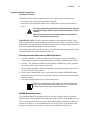
Introduction
The Motorola Solutions MW810 Mobile Workstation series is Motorola Solutions highestperforming and most rugged data communication and computing solution. It is specifically
designed for the harsh conditions of the mobile environment which is unsuitable for
conventional laptop or desktop computers.
The MW810 Mobile Workstation consists of three separate interconnected components: CPU
Box, Display, and Keyboard. The system can be mounted in dual airbag-equipped vehicles
with proper equipment and mount selections. Using custom-designed cable adapters, the
CPU can be connected to a 12.1” or 8.4” MW810 Mobile Workstation display or 3rd-party
display with DVI/RGB interface. Each component can also be used as a stand-alone product
interfacing to 3rd party equipment.
The MW810 Mobile Workstation is a multipurpose mobile data computer. A single
Operating System (OS) can simultaneously support the operation of two independent users
(with independent hardware cursor control), each using different display (RGB or DVI) and
keyboard. A basic model is available without an expansion option, support a single analog
(RGB) or digital (DVI) display.
The MW810 Mobile Workstation design provides a superior computing and broadband
communications solution for mission-critical vehicles:
• Versatile Three-Piece Design.
• Third Generation Intel Core i Series CPU platform.
• Mobile radio connectivity and computing power for vehicle users.
• Flexibility and ease of installation in space-limited vehicles. Mechanical connections to
Fixed-Mount System for Vehicles.
• Sealed housing.
• Protection against extreme temperatures: automatic heating of hard drive disk when
temperature drops below 41°F (5°C).
• Protection against extreme shock and vibration for confidence in mobile environments and
under stressful conditions.
• Withstands vehicle cranking conditions.
• Removable Hard Disk Drive (HDD) or Solid State Disk (SDD).
• Easy access to Express Card and Subscriber Identity Module (SIM) cards.
• Internal GPS module options (including dead reckoning) work with user applications to
provide accurate vehicle location to manage fleet and deploy resources more effectively.
• Optimized for Wireless including internal wireless wide area network (WWAN), wireless
local area network (WLAN), Bluetooth (BT), and Global Positioning System (GPS)
options.
• Expanded wireless networking capabilities, including internal cellular modem options, for
better access to information.
2
MW810 Mobile Workstation Vehicle Installation Manual
• Display units with high contrast and backlight offer outstanding performance even in the
most difficult lighting conditions. Display design enables shortcuts to the most important
user functions.
• Connection to an Automatic License Plate Recognition (ALPR) system (option).
The ALPR system captures an image of license plates, processes it and compares the plate
number against data base or hot list.
Each of the four optional ALPR camera housings integrate an infrared and color cameras.
For more information on the ALPR system, refer to PIPS Technology at: http://
www.pipstechnology.com/.
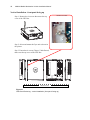
How to identify the workstation release number
This manual relates to MW810 Mobile Workstation Release 2.0. The release number reflects
the type of hardware and software installed inside the MW810 Mobile Workstation.
When receiving the MW810 Mobile Workstation, the release information is included with
the documentation attached to the shipping package.
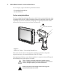
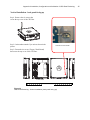
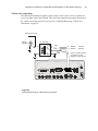
To identify the release number after
Figure 1
Release Number on MW810 Mobile Workstation Units
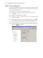
Click Start In and in the search box enter msinfo32. Your workstation's CPU type will
appear in the processor description.
The following CPU types should be displayed:
Introduction
• Intel® CoreTM i7-3610QE 2.3 GHz Quad core processor
• Intel® CoreTM i5-3610ME 2.7 GHz Dual core processor
• Intel® CoreTM B810 1.6 GHz Celeron processor
3
4
MW810 Mobile Workstation Vehicle Installation Manual
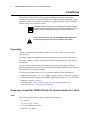
Installation
This section describes the tools and equipment, planning requirements, and product
inspections necessary for a smooth installation of the MW810 Mobile Workstation. Proper
planning will help to ensure that the installation is completed without difficulty and that no
damage occurs to the units or the vehicle.
The MW810 Mobile Workstation is a reliable product when installed
correctly. However, performance can be seriously impaired if it is not
installed correctly. Thoughtful planning can make the difference.
Note
!
Please note that installing any part of the MW810 Mobile Workstation
must be according to the instructions provided in this manual.
Warning
Unpacking
Unpack your shipment and check the contents to ensure that you have received all the
specified items.
Thoroughly inspect the equipment for shipping damage as soon as possible after delivery.
Report any damage you find to your Motorola Solutions Customer Service representative
immediately.
Save the packing carton and anti-static plastic bags for storage and shipping. Both the
shipping carton and the anti-static bags protect the MW810 Mobile Workstation components
from physical and electrostatic damage.
The following optional parts can be used to mount the MW810 Mobile Workstation:
• Display mount assembly - see “12.1“ Display” on page 14 and “8.4” Display” on page 18.
• CPU Box Mounting Trunnion for the MW810 Mobile Workstation CPU - See “CPU Box
Mounting Trunnion” on page 31.
• 3rd Party Mounts - http://www.havis.com/, http://www.gamberjohnson.com/,
www.rammount.com/, www.precisionmounts.com/
Preparing to Install the MW810 Mobile Workstation Inside the Vehicle
Tools
The following tools and service aids are required for installation:
• 3/8” nut driver
• 1/2”, 3/8” or 7/16” wrench
• No. 2 and 4 Phillips screwdriver
• Drill with 3/16” drill bit
Installation
5
Planning
Be sure to consider the following issues when planning the installation:
• Keyboard and display location relative to air bag deployment zones
• Environmental considerations
• Electrical guidelines
• Liquid Propane (LP) gas warning
• Usability by driver/operator
• Vehicle vendor instructions
• Local vehicle authority regulations/design rules
!
Caution
When installing the MW810 Mobile Workstation, make sure that the
CPU Box Mounting Trunnion or any support is tightly anchored to the
vehicle structure. Wobbly Mounting Trunnion can damage the
workstation.
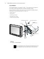
MW810 Mobile Workstation Mounting Location
The MW810 Mobile Workstation is typically installed on a Mounting Trunnion assembly,
which affixes directly to the vehicle transmission hump or to the tunnel plate (preferred and
not included in the kit).
Using an optional tall pedestal under the MW810 Mobile Workstation is recommended only
for use in vehicles where air bag compliance is not required. An example of this is a utility
van which does not have passenger-side air bags for the given model year.
!
To avoid radio Interference, the distance between the display and CPU
Box mounting locations must be more than 8 inches (20 cm).
Caution
Correct positioning of the components will ensure that the MW810 Mobile Workstation
meets the following requirements:
• The display and keyboard are within easy reach of the driver/operator (more difficult due
to air bag constraints).
• It will not injure the operator or passenger in case of an accident.
• The display does not interfere with the driver’s vision.
• The display and the CPU Box are properly ventilated.
• Place the CPU Box so that it can be easily removed for servicing.
• Do not mount the MW810 Mobile Workstation and route its cables where they can be
damaged, kicked by the driver’s or other passenger’s foot.
• Verify that the MW810 Mobile Workstation will not interfere with operation of the vehicle
and will not hinder the driver when driving the vehicle.
• Verify that the mounting surface is able to support the weight of the display and the CPU
Box.
6
MW810 Mobile Workstation Vehicle Installation Manual
• To cool the MW810 Mobile Workstation, allow sufficient space around the CPU Box for
free air flow.
• Select a location for the CPU Box that permits routing the RF antenna cable as directly as
possible.
• If you are mounting the display on a plastic dashboard, you must first reinforce the
dashboard; otherwise the weight of the display may crack or break the dashboard.
• Do not mount the CPU Box on a flat or concave surface where the unit could become
partially submersed in water.
Air Bag Considerations
When planning the installation of communication equipment in a vehicle with one or more
air bags, proceed as follows:
• Installation of vehicle equipment should be performed by a professional installer/
technician qualified in the requirements for such installations. An air bag’s size, shape and
deployment area can vary depending on vehicle make, model and front compartment
configuration (e.g., bench seat vs. bucket seats).
• Contact the vehicle manufacturer’s corporate headquarters, if necessary, for specific air
bag information for the vehicle make, model and front compartment configuration
involved in your equipment installation.
Installation
7
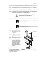
Provided for your reference are several air bag deployment zone templates from automobiles
used in public safety roles (Figure 2, Figure 3 and Figure 4).
!
Caution
Vehicles equipped with air bags:
An air bag inflates with great force. DO NOT place objects, including
communication equipment, in the area over the air bag or in the air bag
deployment area. If the communication equipment is improperly installed and the
air bag inflates, this could cause serious injury.
Copyright © 2002 Ford Motor Company
Figure 2
Air Bag Deployment Zones - Crown Victoria
8
MW810 Mobile Workstation Vehicle Installation Manual
A
.
D
127 mm
(5 in.)
B
C
127 mm
(5 in.)
E
F
G
H
I
J
K
200 mm
(7.8 in.)
200 mm
(7.8 in.)
HEAD CURTAIN AND FRONT SEAT-MOUNTED SIDE IMPACT AIR BAG1 DEPLOYMENT ZONES
VIEW FROM REAR SEAT, RIGHT SIDE IS MIRROR OF LEFT SIDE
A.
B.
C.
D.
E.
F.
Vehicle center-line
Headrest
Center-line of occupant
Edge of headliner
Door inner trim panel
Center body pillar trim
C
G.
H.
I.
J.
K.
N
A
B
Head curtain air bag zone
Bottom of door windows
Front door handle
Front seat back thorax air bag zone
Seat back
O
M
D
L
E
K
F
130 mm
(5.1 in.)
130 mm
(5.1 in.)
680 mm
(25.7 in.)
625 mm
(24.6 in.)
G
H
470 mm
(185 in.)
420 mm
(16.5 in.)
150 mm
(5.9 in.)
J
I
).3425-%.40!.%,!.$!002/8)-!4%$%0,/9-%.4!2%!/&4(%$2)6%2!.$&2/.40!33%.'%2!)2"!'31
VIEW FROM TOP
A.
B.
C.
D.
E.
Vehicle center-line
Driver center-line
Front of instrument panel at the windshield base
Driver door trim
Driver knee air bag (model year 2013)
F.
G.
H.
I.
J.
Instrument cluster
Rear-most instrument panel
Steering wheel
Driver air bag
Front passenger air bag
K.
L.
M.
N.
O.
Glove box
Front passenger knee air bag (model year 2013)
Front passenger door trim
Front passenger center-line
Radio stack
1. Head curtain side air bags are designed to help reduce the risk of head and neck injuries to front and rear seat occupants on the near side of certain side-impact collisions.
Always use safety belts and the correct child restraints for your child’s age and size, even in vehicles equipped with air bags. Children are safer when properly secured in a rear
seat. See your vehicle Owner’s Manual and child safety seat instructions for more information.
/05&"MMEJNFOTJPOTBSFBQQSPYJNBUFBOETVCKFDUUPDIBOHF
Figure 3
Air Bag Deployment Zones - Chevrolet Caprice
Copyright © 2012 General Motors
Installation
9
.
SIDE VIEW OF DRIVER SIDE
AIR BAG DEPLOYMENT ZONE
A. Top edge of windshield
B. Top of instrument panel
C. Inflated air bag – steering wheel
D. Centerline of steering column at mid-tilt
E. Driver air bag deployment zone
F. Front of steering wheel
SIDE VIEW OF PASSENGER SIDE AIR BAG
DEPLOYMENT ZONE
A. Top edge of windshield
B. Inside rearview mirror
C. Instrument panel top surface zone
D. Passenger side air bag module trim panel – rear edge
E. Inflated air bag – horizontal dimension approximate 15.4 in (390 mm)
F. Inflated air bag – vertical dimension approximate 9.3 in (490 mm)
G. Inflated air bag – instrument panel
H. Passenger air bag deployment zone
HEAD CURTAIN AND FRONT SEAT-MOUNTED SIDE IMPACT AIR BAG DEPLOYMENT ZONES
VIEW FROM REAR CARGO AREAF
A. Head curtain air bag deployment zone
B. Underside of headliner
C. Edge of headliner
D. Inner center pillar trim
E. Inner door pad
F. Seat centerline
G. Bottom of door windows
H. Front seat headrests
I. Seat-mounted side impact air bags deployment zone front seat
J. Top surface of outboard front seat cushion
Head curtain side air bags are designed to help reduce the risk of head and neck injuries to front and rear seat occupants on the near side of certain side-impact collisions. Always
use safety belts and the correct child restraints for your child’s age and size, even in vehicles equipped with air bags. Children are safer when properly secured in a rear seat. See
your vehicle Owner’s Manual and child safety seat instructions for more information.
/05&"MMEJNFOTJPOTBSFBQQSPYJNBUFBOETVCKFDUUPDIBOHF
Copyright © 2012 General Motors
Figure 4
Air Bag Deployment Zones - Chevrolet Tahoe PPV & 5W4
10
MW810 Mobile Workstation Vehicle Installation Manual
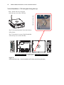
Equipment Ventilation
The display, keyboard and CPU Box are designed to operate properly in an ambient
temperature range of -22°F to 158°F (-30°C to +70°C). The MW810 Mobile Workstation
CPU must be installed in an area with adequate air flow to allow for proper ventilation.
Installers must install the CPU in an unobstructed location in order to allow proper air flow
(see Figure 5). It is imperative to avoid installing the CPU in an enclosure or next to heat
generating equipment such as: radio transmitters, power amplifiers or a cabin heater.
Clear 0.8” (20 mm)
Clear 0.8” (20 mm)
Clear 0.8” (20 mm)
Air Outlet
from Fans
Clear 0.8” (20 mm)
Air Inlet to Fans
Air Outlet from Fans
Air Inlet to Fans
Figure 5
Clear Ventilation Area Around the CPU Box
Drilling Holes
• Where possible, use existing holes in the fire-wall, the trunk wall and the channels above
or beneath the doors. Run cables parallel to existing car cables if appropriate.
• When holes must be drilled, verify that other wiring, break lines or gas lines are not
damaged.
• When drilling a hole in the roof, take care not to snag the roof liner.
• To prevent rusting after drilling, remove all metal burrs and residue, and completely clean
the area to ensure that all steel dust is removed.
Installation
11
• Insert rubber grommets in all drilled holes to protect cables.
• Create permanent driplines (low points) on all cable routes before cables enter roof holes,
to help prevent water intrusion.
Electrical Guidelines
The power range requirement for operating the MW810 Mobile Workstation is 13.8 VDC +/
- 20% in a 12V battery, 16.5A (maximum) system, negative ground vetting or 27.6 VDC +/20% in a 24V battery, 10A (maximum) system, negative ground vetting.
Be sure that the vehicle’s electrical system is in good condition. Faults in the alternator and
ignition system can be a source of severe Radio Frequency Interference (RFI) and can result
in operating problems. Correct any problems in the alternator output, ignition system, and
check the battery condition before beginning the installation.
!
DO NOT install the workstation in a vehicle with a positive-ground electrical system.
Caution
The vehicle must have an alternator that can produce a high-current output at low speed
(below 18 m.p.h. or 29 km/h) and in an idle state. It also needs the highest rated heavy-duty
battery available for the vehicle. The power cables of the MW810 Mobile Workstation
should be directly connected to the power system of the vehicle.
!
Caution
Avoid using power Battery Saver relays that cut-off power ruthlessly between the
MW810 Mobile Workstation main power and the power system of the vehicle.
Uncontrolled power cut-off can damage the MW810 Mobile Workstation
operating system, cause loss of data and may require re-imaging of the hard
drive. If a power cut-off device is used in order to conserve vehicle battery life,
consult a qualified Motorola Solutions authorized installation shop or contact the
Motorola Solutions System Support Center for assistance.
Ground Polarity
The MW810 Mobile Workstation should operate only in negative ground electrical systems.
Check the ground polarity of the vehicle before starting the MW810 Mobile Workstation
installation to verify that the polarity is correct. Accidentally reversing the polarity will not
damage the MW810 Mobile Workstation, but will cause the cable fuses to blow.
Due to advanced vehicle assembly techniques, different parts of the vehicle chassis may not
be connected to the battery negative terminal. Connecting the ground leads of several devices
with a common power supply into different location on the chassis, may cause GROUND
potential differences between these locations and damage the MW810 Mobile Workstation or
any other installed equipment.
FIRST CHECK that the vehicle chassis point to which you are about to connect the
negative lead is properly connected to the battery negative terminal. If the chassis is not
properly grounded, connect the negative lead directly to the battery's negative terminal.
When the CPU Box and the display are mounted on a Gamber Johnson mount or next to each
other, use a 10AWG ground wire to connect between the body of the CPU Box and the
12
MW810 Mobile Workstation Vehicle Installation Manual
display. The ground wire ring lugs should be connected, on one side, to one of the screw
holes used to secure the CPU Box to the trunnion, and on the other side, to one of the screw
holes used to secure the display to a surface.
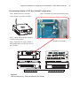
VERY IMPORTANT: Connect the GROUND lead of any device that is connected to the
MW810 Mobile Workstation, i.e., radio or any other equipment, to one common chassis
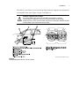
point, via a ring lug, as shown in Figure 6. Please ensure that the chassis point has been
cleaned and scraped of any dirt, paint or other material that may prevent a good electrical
connection.
MW810 Mobile Workstation
Other electronic equipment
MW810 Mobile Workstation
CPU Box
Any Device
An additional
Lug on Chassis
MW810 Mobile
Workstation Display
Chassis
Figure 6
Wire Connection to Battery and Lead Connection to Chassis
If one ring lug cannot hold all the wires, add an additional ring lug and connect it to the
battery's negative terminal (-) or to the same chassis point by using the same installation
screw. Connect this common lug to the common, grounded chassis point or to the battery's
negative terminal (-) as shown in Figure 6. Make sure that all the ring lugs are placed on
clean and unpainted surfaces.
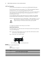
Power Cable Installation
1. Determine a routing plan for the power cable, taking into consideration the location at
which the unit is to be mounted, and the location of the vehicle battery.
2. In order to pass the power cable through the fire wall and into the engine compartment,
locate an existing hole with a grommet in the vehicle fire wall, or drill a 10 mm (0.4 inch)
access hole at the desired location. Insert a grommet with a 5 mm (0.2 inch) inner
diameter into the access hole to avoid damage to the cable (see Figure 7).
To MW810 Mobile Workstation
Figure 7.
Cable Routing into Engine Compartment
Take special care not to damage any existing vehicle wires.
Installation
13
3. From inside the vehicle, route the red and black power cable leads (without lugs attached)
through the access hole into the vehicle’s engine compartment, using accepted industry
methods and standards.
4. Locate the nearest available vehicle chassis ground mounting point and shorten the black
lead to remove excess cable length.
5. Install the supplied ring lugs onto the stripped end of the black lead, and onto the fuse
holder at the end of the red lead (see Figure 8).
For 13.8 VDC +/- 20% System, use 15A Fuse
For 27.6 VDC +/- 20% System, use 10A Fuse
Figure 8
Power Cable Assembly
6. Position the fuse holder as close as possible to the battery, ensuring that it is not close to
any hot engine component.
7. Mount the fuse holder, and dress wires as necessary. Connect the red lead plug adaptor
(on the fuse holder) to the matching receptacle on the red power cable.
8. Connect the black lead to the vehicle chassis ground. DO NOT connect the black lead
directly to the battery’s negative (–) terminal.
9. Remove the fuse from the fuse holder and connect the red lead of the power cable to the
positive (+) battery terminal. Verify that the adaptor cable is connected to the red lead of
the main power cable.
10. Plug the fuse into the fuse holder.
!
Failure to mount the red lead of the power cable directly to the battery
may result in severe alternator whine interference.
Caution
Cable Routing
• Before a wire is run or a hole is drilled, inspect the vehicle and determine how and where
you intend to mount the antenna, CPU Box and display.
• Plan wire and cable routing to provide maximum protection from overheating, battery
acid, moving parts and sharp edges.
• Keep cables away from ignition circuits to reduce noise pickup in the radio equipment.
14
MW810 Mobile Workstation Vehicle Installation Manual
• Verify that the cables are of sufficient length. Do not connect two short lengths with a
connector; doing so will result in signal loss. Refrain from loose excess in the cables, but
leave enough slack to allow reconnecting if necessary.
• Do not run cables externally or underneath floor mats.
• Do not locate cables where they can be kicked by the driver or passengers or where they
can interfere with operation of the driver’s foot pedals.
• When routing the cable, refrain from creating sharp bends or kinks.
• Cables longer than 10 ft. (3.05 m) should be routed through special UL listed conduit/duct
for electrical cables. This conduit/duct should fully enclose the cable along its whole
length.
• Do not overtighten any tie wraps.
12.1“ Display
The 12.1 display is attached to the display mount by Phillips screws (10mm, M4), supplied in
the display shipping package. The CPU to Display Signal Cable is routed from the CPU Box,
through the mount, and connected to the lower back side of the display (see Figure 9).
!
Use caution when connecting the display to CPU cable. Rough
installation may damage the connectors/receptacles of the display,
cable or CPU Box.
Note
To interface the MW810 R2.0, 12.1” Display to a legacy MW810 CPU
Box, use CPU Box to Display R2.0 to Display (50 pin to 60 pin) adaptor
cable - P.N: FKN00010.
When interfacing the MW810 R2.0, 12.1” Display to a legacy MW810
CPU Box, software installation is also required. (See MW810 Mobile
Workstation, R2.0, Administrator Guide P.N 6802988C42.)
Caution
Form a service loop for the Power and Display Signal Cables to reduce cable tension. Use
plastic cable tie wraps to secure the cables to cable tie points. Do not overtighten the tie
wraps.
The Function keys of the display include an illuminated area designed
for description labels. Contact your Motorola Solutions representative
for assistance ordering custom-made labels as needed.
Note
Installation
11.5”
3.34”
2.61”
7.4”
9.6”
1.92”
10.7”
Figure 9
12.1” Display Size and Cable Route on Mount
Allow Service Loop
Power Cable
CPU to Display
Signal Cable
USB Keyboard Cable
15
16
MW810 Mobile Workstation Vehicle Installation Manual
!
Warning
!
To comply with safety regulations, the distance between the
display mounting location and people sitting inside the vehicle
must be more than 8 inches (20cm).
• Long Display Signal Cables (longer than 3 Meters, 10 feet) should be routed
inside protective ducts to avoid damage.
Caution
• The MW810 Mobile Workstation Display is shipped with a protective film that
covers the touch screen. Once installation is completed, the protective film must
be removed to avoid damage to the touch screen during operation. If any residue
from the protective film remains upon removal, use a dry soft cloth and gently
rub it off, toward the center of the display so it does not wedge into the bezel of
the touchscreen.
Connection to Standard Personal Computer
12.1” Display to DVI (or RGB) Standard CPU Cable enables to interface the MW810, 12.1”
Display to any personal computer.
Interfacing the MW810, 12.1” Display to a standard laptop or personal computer with DVI
connection requires the following components:
• 12.1” Display to DVI Standard CPU - P.N: FKN8454
• Adaptor Cable - FKN000100
Interfacing the MW810, 12.1” Display to a standard laptop or personal computer with RGB
connection requires the following components:
• 12.1" Display to RGB Standard CPU - P.N: FKN84493
• Adaptor Cable - FKN000100
For cable connection, refer to Figure 10.
Standard Laptop or
Personal Computer
12.1 MW810 Display
DVI or RGB
Connector
Adaptor Cable
USB Connector
(male type)
12.1” Display to DVI (or RGB)
Standard CPU Cable
Speaker Jack
Not used (Green wire)
Figure 10
Connection of MW810, 12.1” Display to a Standard Personal Computer
Installation
17
The following table describes the connectors of the MW810, 12.1” Display to Laptop or
Standard Personal Computer.
Connector
Description
RGB or DVI
RGB or DVI signals from the personal computer to display.
USB 2.0
USB communication with the personal computer.
This communication enables operation of the function buttons,
emergency button and Power button for turning the workstation
On/Off.
Speaker Jack
Audio signal from the personal computer to display speaker.
18
MW810 Mobile Workstation Vehicle Installation Manual
8.4” Display
The 8.4” Display can be attached to a mount by four 10mm, M4 screws.
9.1"
3.93"
W 1.7"
7.1” 3.93"
Figure 11
8.4” Display Size
The CPU box to Display cable can be ordered in two basic
configurations with various lengths:
Note
1) Right side driving countries (driver's seat on left-hand side). Seen
from the front, cable exits to the right away from the driver (see Figure
11).
2) Left side driving countries (driver's seat on right-hand side). Seen
from the front, cable exits to the left, away from the driver.
When
To interface the MW810, 8.4” display to a MW810 CPU Box R2.0, use
CPU Box R2.0 to Display (60 pin to 50 pin) adaptor cable P.N:
FKN0003. When
Note
When interfacing the MW810, 8.4” display to a MW810 CPU Box R2.0,
software installation is also required. (See MW810 Mobile Workstation,
R2.0, Administrator Guide P.N 6802988C42.)
The Function keys of the display include an illuminated area designed
for description labels. Contact your Motorola Solutions representative
for assistance ordering custom-made labels as needed.
Note
Installation
This page intentionally left blank
19
20
MW810 Mobile Workstation Vehicle Installation Manual
The 8.4” Display supports the following installation methods:
• Free-standing Pedestal Mount
• In-dash DIN Mount
The Free-standing Pedestal Mount
The Free-standing Pedestal Mount affixes to the vehicle’s floor or transmission hump using
self tapping screws or bolts. It allows the display mount to be readjusted to either the driver
or passenger side for most comfortable viewing angle. A single adjustment knob enables
adjustment of both upper and lower ball joints simultaneously.
Four 10mm, M4 Screws
Adjustment Knob
Figure 12
MW810 8.4” Display - Free-standing Pedestal Mount
This section describes the tools and equipment, planning requirements, and product
inspections necessary for a smooth installation of the 8.4" Display.
Proper planning will help to ensure that the installation is completed without difficulty and
that no damage occurs to the units or the vehicle.
!
The 8.4" Display is a reliable product when installed correctly.
However, performance can be seriously impaired if it is not installed
correctly. Thoughtful planning can make the difference.
!
Installing any part of the 8.4" display must be according to the
instructions provided in this manual.
Caution
Warning
Installation
.
21
To install the Free-standing Pedestal Mount, perform the following steps (see Figure 13):
Step 1. Select the location to achieve optimal functionality and use of the 8.4" Display.
Step 2. If screws and nuts are used for anchoring the mount, mark the hole locations using the
base of the mount and drill four 5.5 mm holes into the dashboard.
Step 3. If self-tapping screws are used for anchoring the mount, attach the mount to the
desired location and drive the screws into the dashboard.
!
Caution
Be careful not to drill or drive screws into wires, circuits or
equipment located under the dashboard
Step 4. Connect the display to the VESA Plate and secure using four screws and washers.
Note
Note
The pedestal mount can be assembled to the VESA plate on
both of it's base end sides.
It is very important to use spring washers when securing the
display to the Display Bracket.
Step 5. Connect the display signal
cable and the power cable
to the display.
Step 6. Using four screws, install
the display to the pedestal
Mount.
M4, 16 Screw
VESA Plate
Step 7. Adjust the display position.
Step 8. Route the Display Signal
and Power cables down to
the CPU Box. Ensure that
the cables have enough
slack to move when the
display is tilted up/down or
swiveled.
For cable connections, refer to
steps 5 to 7 of “To assemble and
install the Display DIN Mount,
perform the following steps (see
Figure 16):” on page 24.
0.22” D Screw Hole
Figure 13
8.4” Display - Free-standing pedestal mount
22
MW810 Mobile Workstation Vehicle Installation Manual
In-dash DIN Mount
The In-dash DIN Mount is a rectangular (2” high x 7” wide) mount that can be adapted to
most vehicles produced today that contain a standard ‘Single DIN’ opening.
During installation, the display can be adjusted to provide optimal accessibility using the
following pivot and mounting adjustments (see Figure 14):
• Swivel: up to 13°
• Tilt: up to 35°
• Vertical: up to 70 mm
• Horizontal: up to 30 mm
• Extension out: up to 48 mm
Swivel Adjustment Screws
Four 10mm, M4 Screws
Horizontal
Adjustment Holes
13° Swivel
In/Out
48 mm
Up/Down
70 mm
Vertical
Mounting
Holes
°
35 Tilt
Left/Right 30 mm
Tilt Adjustment
Screws
Figure 14
8.4" Display - In-dash DIN Mount
.
Note
The In-dash DIN Mount has no parts that can be adjusted by the user.
Mount readjustment can only be performed by service technicians.
Installation
To mount the DIN sleeve inside the radio slot, perform the following steps:
Note
The DIN mount can only be adjusted during installation and may
require reinstallation before the final position is determined. No enduser adjustment is available.
The following installation steps may change according to your specific
vehicle model and application requirements.
Step 1. Remove the radio (if exists) from radio slot in the vehicles dash.
Step 2. Route the display signal cable and the power cable through the radio slot in the
vehicles dash.
Step 3. Slide the DIN sleeve into the slot in the vehicle dash and route the display signal
cable and the power cable through the sleeve.
Step 4. When the sleeve is fully inserted and the front edge or lip is seated, secure the sleeve
to the radio slot by bending the tabs on the sleeve behind the plastic of the dash.
Back Anchor Holes
Radio (DIN) Slot
Bottom Anchor Holes
DIN Mount Sleeve
Tabs
Figure 15
8.4” Display - Installation of DIN Sleeve
!
Warning
Side Anchor Holes
To ensure maximum safety, the DIN sleeve must be fastened to the
vehicle using the back, and/or side and bottom anchor holes.
23
24
MW810 Mobile Workstation Vehicle Installation Manual
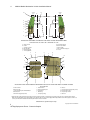
To assemble and install the Display DIN Mount, perform the following steps (see Figure 16):
Step 1. Position the left-hand side and right-hand side Arm Brackets inside the DIN Sleeve.
Use the holds on the arms to determine the distance of the display from the dash, and
fasten the arms using four nuts to inner studs.
DIN Mount Sleeve
Arm Bracket
Tilt Bracket
Swivel Bracket
Arm Bracket
Swivel Plate
Display Bracket
Figure 16
8.4” Display - DIN Mount Breakdown
Note
Vehicle vibrations may loosen the mount parts. It is very
important to use the spring washers when assembling the
display mount.
Step 2. Use four screws to connect the left-hand side and right-hand side Arm Brackets to the
Tilt Bracket. Pivot the Tilt Bracket up/down to determine the display tilt position and
secure the four screws.
Step 3. Route the display signal cable and the power cable through the opening in the Tilt
Bracket.
Step 4. Use four screws to connect the Swivel Bracket to the Display Bracket. Use the line of
holes on the Display Bracket enable to determine the display height position and
connect the display using four screws.
Installation
25
Step 5. Plug the connector of the display signal cable and use the three screws to secure the
connector to the display.
Step 6. Note that cables are available with right-side or left-side display exit for right-side or
left-side driver seat position.
!
Caution
!
Caution
Use caution when connecting the display to CPU cable. Rough
installation may damage the connectors/receptacles of the display,
cable or CPU Box.
To avoid damage to the display and CPU Box, verify that the Main
Power switch, located on the back panel of the CPU Box, is turned Off
before connecting cables to the display.
Step 7. Plug the keyboard cable to the USB port and secure the cable to the display by using
the thumb screws.
The maximum current load from USB 2.0 port is 500mA.
Note
Use the rubber plug, provided with this product, to seal the port when
not in use.
Step 8. Plug the power cable to the power connector on the back of the display.
Center Screw Hole
Swivel Bracket
Side Screws
Center Screw
Use Cable Clamp
VESA Plate
Power Connector
USB 2.0
Port for
Temporary
Connection
of Devices
Filters
USB 2.0 Port
for keyboard
Power Cable
Display Signal Cable
Figure 17
8.4” Display - Installation of Cables
Note
15A SB Fuse
Keyboard Cable to USB 2.0 Port
The display is powered directly from the vehicle power system. The
display software uses power management tools to prevent excessive
battery drainage during normal operation and vehicle start.
26
MW810 Mobile Workstation Vehicle Installation Manual
Step 9. Assemble the Swivel Bracket (connected to the VESA plate) to the Tilt Bracket. The
Swivel Bracket determines the pivot position of the display.
Step 10. Use the center screw slot on the Swivel Bracket to align the display and set the
swivel angle, then fasten using the two side screws and Swivel Plate.
Connection to Standard Personal Computer
The Laptop to MW810, 8.4” Display Signal Cable (optional DVI, P.N: FKN8547 or RGB,
P.N: FKN8546 cable) enables you to interface the MW810, 8.4” Display to any laptop or
personal computer. For cable connection, refer to Figure 18.
Standard Laptop or Personal Computer
Optional Left Exit Cable
RGB or DVI Connector
USB Connector (male type)
Laptop to MW810, 8.4” Display Signal Cable
Speaker Jack
Not used (Green wire)
Figure 18
Connection of MW810, 8.4” Display to Laptop or Standard Personal Computer
The following table describes the connectors of the MW810, 8.4” Display to Laptop or
Standard Personal Computer.
Connector
Description
RGB or DVI
RGB or DVI signals from the personal computer to display.
USB 2.0
USB communication with the personal computer.
This communication enables operation of the function buttons,
emergency button and Power button for turning the workstation
On/Off.
Speaker Jack
Audio signal from the personal computer to display speaker.
Installation
27
CPU Box
The MW810 Mobile Workstation CPU Box should be mounted so that cables coming from
the keyboard(s), display(s), power system and peripherals can be attached easily to the
connector panel. The maximum length of the display signal cable is 5 meter (16.4 feet).
Whenever one of the MW810 Mobile Workstation receptacles is not in use, it is
recommended to leave the receptacle plug. Use the supplied rubber plugs to cover the unused
receptacles (see Figure 19).
Rubber Plugs
Figure 19
CPU Box - Rubber Plugs
Express Card Slot
The Express Card Slot is used for memory storage express card size 34mm or 54mm. The
card is installed inside the CPU Box in the Express Card Slot (see Figure 20).
Express Card & SIMs
Compartment Door
Express Card
R2.0
Express Card Slot
Figure 20
CPU Box - Express Card Installed in the Express Card & SIMs Compartment
28
MW810 Mobile Workstation Vehicle Installation Manual
SIM Card Installation
The MW810 Mobile Workstation requires a SIM card to activate the WWAN radio. The SIM
card fits inside the Express Card & SIMs Compartment. The SIM card holds the MW810
Mobile Workstation identification information required for connecting to a cellular network.
To install a SIM card for the first time, perform the following steps:
!
Caution
Before installing the SIM card, verify that MW810 Mobile
Workstation is turned off.
Inserting or removing the SIM card when MW810 Mobile
Workstation is running can corrupt the SIM card information.
Step 1. Open the Express Card & SIMs Compartment Door.
Step 2. Retrieve the SIM Card Drawers from a red plastic bag inside the CPU Box package.
Step 3. Install the two SIM Card Drawers inside the Express Card & SIMs Compartment.
Verify that the left drawer indicates SIM1 and the right drawer indicates SIM2. Slidein the drawers and verify that they are locked in place.
Step 4. Press the Eject Button of SIM1 Card Drawer (for WWAN1 radio) and slide-out the
SIM Card Drawer.
Step 5. Place the SIM Card inside the SIM1 Card Drawer. Make sure that the gold plate of
the SIM card is facing up and the notch of the SIM card fits in the proper direction
inside the SIM1Card Drawer.
Step 6. Slide-in to lock the SIM1 Card Drawer.
Step 7. Close the Express Card & SIMs Compartment Door.
SIM1 Card Drawer
SIM Drawer Eject Button
Express Card & SIMs Compartment Door
SIM2 Card Drawer
(currently not in use)
Figure 21
CPU Box - SIM Cards Installation
Installation
29
Hard Disk Drive/Solid State Disk Compartment
The CPU Box is supplied with a removable Hard Disk Drive (HDD) or Solid State Disk
(SSD) that interfaces to the CPU Box enclosure via a SATA3 connector.
R2.0 CPU Boxes do not support legacy R1.X HDD or SSD enclosures.
Legacy R1.X HDD or SSD enclosures are not interchangeable with R2.0 enclosures. To
Identify R2.0 HDD or SSD, look for the R2.0 mark on the front panel of the enclosure.
The HDD is equipped with a built-in heater that automatically turns on at low temperatures.
When the temperature drops below 41°F (5°C), a built-in heater starts operating to maintain
the HDD in working conditions. If the HDD temperature is below 41°F (5°C) during bootup, a message is issued indicating that the heater is starting to operate and slightly delaying
start-up due to time-out of HDD heater function.
Note
The SSD does not require/include a heater to operate at low
temperatures.
To remove the HDD/SSD unit:
Step 1. Shut down the MW810 Mobile Workstation.
Step 2. Switch off the On/Off power switch located at the backpanel of the CPU Box (see
Figure 3).
Step 3. Loosen the two screws securing the HDD/SSD Unit to the CPU Box (see Figure 6).
Step 4. Pull out the HDD/SSD Unit from the HDD/SSD Unit Compartment in the CPU Box.
CPU Box
HDD/SSD Unit
Screws
HDD/SSD Unit Compartment
Figure 22
CPU Box - Removal of Hard Disk Drive/Solid State Disk Unit
30
MW810 Mobile Workstation Vehicle Installation Manual
!
Caution
1. Never try to remove the HDD/SSD unit before shutting
down the workstation and switching off the On/Off power
switch on the backpanel of the CPU Box. Doing so can
result in loss of data, and can damage the workstation and
the sensitive circuitry of the HDD.
2. Make regular backups of data from your HDD to an
external flash disk or other storage media.
3. Once the HDD/SSD Unit is removed from the HDD/SSD
Unit Compartment, the CPU Box is not sealed. In such
condition, do not expose the CPU Box or HDD/SSD Unit
to sand, dust, liquid or extreme humidity.
The CPU Box Mounting Trunnion
When installing the CPU Box, a Mounting Trunnion (see Figure 23) should always be used
unless an alternate method or other mounting option is specifically certified by Motorola
Solutions.
The CPU Box can be mounted at any place in the passenger compartment that provides
adequate ventilation (see Figure 5).
It is recommended that the CPU Box be mounted in a place where the removable HDD/SSD
enclosure, Express Card & SIMs Compartment can be easily accessed. Attach the adhesive
tape, provided in the shipping carton, to the Express Card to enable easy removal of the
Express Card from the Express Card & SIMs Compartment.
Suggested locations for CPU Box installation, in order of preference, are: on the trunk tray,
on the front of the prisoner cage, under the dashboard, inside the console, or under the seat
(not in the direct path of the vehicle heater air flow).
The CPU Box Mounting Trunnion is attached to the CPU Box by four bolts supplied with the
Mounting Trunnion. The Mounting Trunnion can be affixed to a flat surface by eight bolts
(not included).
Installation
31
The CPU Box Mounting Trunnion enables the CPU Box to be mounted on the flat surface or
pedestal. It is recommend to install the Mounting Trunnion within +- 5 degrees of vertical/
horizontal planes to in order for the hard drive anti-vibration system to work properly.
8.1” (206 mm)
0.11” (3 mm)
10.6” (270 mm)
2.55” (65 mm)
0.27” (7 mm)
Figure 23
CPU Box Mounting Trunnion
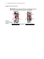
!
Caution
When installing a CPU Box equipped with a GPS Dead Reckoning gyro,
do not exceed + -5 degrees tilt angle from each vehicle axis. Installing
the CPU Box over + -5 degrees tilt angle from one or more of the vehicle
axis may result in gyro reading error while in DR mode.
+5
Tilt angle range example
-5
For GPS Dead Reckoning installation, refer to “Appendix A Installation,
Configuration and Calibration of GPS Dead Reckoning” on page 43
Motorola Solutions recommends the use of the CPU Box Mounting
Trunnion. Failure to do so may result in hard drive damage due to
vibration.
Note
32
MW810 Mobile Workstation Vehicle Installation Manual
Keyboard
The keyboard tray may be placed anywhere in the vehicle. Please ensure that all safety
guidelines and air-bag deployment requirements are met.
When a mounting tray is used, the keyboard is provided with a quick release holder to allow
operation of the keyboard when out of the holder. Care must be used to ensure ample space
for extracting and reinserting the keyboard into the holder. Ensure that the cable is routed in a
manner that allows the operator to remove the keyboard from the mounting tray and operate
the keyboard on the lap.
The all Displays have a standard Universal Serial Bus (USB) type A receptacle to which is
generally used for QWERTY style keyboard. The maximum current load from USB 2.0 port
is 500mA. When a keyboard is used, the keyboard cable connector should be secured to the
display by thumb screws.
Use the rubber plugs provided with Display or CPU to seal unused ports.
!
Warning
All auxiliary devices connected to the display (keyboard or any USB peripherals) must be anchored
or secured to the vehicle. Pull off the road and park before using the keyboard, if driving conditions
or regulations so require.
Failure to comply with this warning may result in body injury or even death in case of vehicle
impact (see example in Figure 24)
Securing Straps
Figure 24
Keyboard Secured in Door Compartment
Installation
33
Interfaces to the MW810 Mobile Workstation CPU Box
With the mechanical installation complete, hook up the optional antennas and other
peripheral devices to the CPU Box and Display.
The MW810 Mobile Workstation offers multiple expansion board options, each with a
different rear panels, so you can add more ports for external modems, video cameras, or other
vehicle peripherals as required.
Figure 25 shows the expansion board options of CPU Box of the MW810.
USB2*
VIDEO
DISPLAY 2
ON
USB
COM 4
LAN
LAN
OFF
LAN
DISPLAY 1
MAIN
AUX
COM 1
W-WAN 1
W-LAN
AUX
W-WAN2
IN
OUT
2
3
1
USB3
USB
MAIN
GPS
AUX
PWR
CPU Box - Extra Display, Video & I/O Expansion Board Option
LAN
DISPLAY 2
LAN
ON
USB
ALPR
OFF
DISPLAY 1
MAIN
AUX
COM 1
LAN
USB
W-WAN 1
W-LAN
AUX
W-WAN2
IN
OUT
2
3
1
MAIN
GPS
AUX
PWR
CPU Box - Extra Display & ALPR Expansion Board Option
ON
OFF
DISPLAY 1
MAIN
AUX
COM 1
LAN
USB
W-WAN 1
W-LAN
AUX
W-WAN2
IN
OUT
2
3
1
MAIN
GPS
AUX
PWR
CPU Box - No Expansion Board Option
eSATA
USB
COM 4
COM 3
USB
ON
OFF
DISPLAY 1
MAIN
AUX
COM 1
LAN
USB
W-WAN 1
W-LAN
AUX
W-WAN2
IN
OUT
2
3
1
MAIN
AUX
GPS
PWR
CPU Box - eSATA & I/O Expansion Board Option
* Although this port has USB 3.0-ready hardware (blue connector type), it is currently configured to USB 2.0
in the BIOS implementation.
Figure 25-CPU Box - Expansion Board Options
34
MW810 Mobile Workstation Vehicle Installation Manual
Figure 26 shows an optional connection layout of the CPU Box with Extra Display, Video &
I/O Expansion Board option to peripheral devices, system and power.
Ensure that the cables are properly routed to prevent damage to the cables and any operator
hazards. Connect the DC Power cables at the end of the connection process.
Important Note: Use the supplied rubber plugs to cover the unused receptacles.
!
CAUTION
Do not connect or disconnect any peripheral device during the boot-up process or when
the CPU is in power-saving mode.
1000 BASE-T LAN2 Network
External Radio
Bluetooth
Ignition Sense Input
Display 2
USB
RS232 Radio interface
USB
1000 BASE-T LAN1 Network
Power Cable
Fuse: 13.8VDC - 15A,
27.6VDC -10A
Digital I/Os (GPIO
Ports)
5 to 27V Power output.
1.5 Amps maximum
USB
1000 BASE-T LAN
Display Signal Cable
VIDEO
ON
USB
COM 4
DISPLAY 2
LAN
LAN
OFF
Display Signal Cable
DISPLAY 1
Bluetooth
MAIN
Display 1
USB
AUX
COM 1
LAN
W-WAN 1
W-LAN
AUX
USB
3
2
W-WAN2
IN
OUT
3
2
1
MAIN
AUX
GPS
PWR
W-WAN2 is not in use
(Future Option)
Fuse: 13.8VDC - 15A,
27.6VDC -10A
USB
Mobile DVR System
Audio
Line
out
USB
Headset
Audio
Line
in
Fuse: 13.6VDC - 15A,
27.2VDC -10A
Wireless LAN
MIMO Antenna
W-WAN1
Antennas
GPS
Antenna
802.11 n
Power Cable
Vehicle
Power
System
Figure 26
Optional Connection Layout of CPU Box with Extra Display, Video & I/O Expansion Board Option to
peripheral devices, system and power.
Installation
35
Expansion Board Connections
Installation Guidelines
Vehicle RF antennas must be installed external to the vehicle and in accordance with:
• The requirements of the antenna manufacturer/supplier.
• Instructions in the installation manual of the external radio (in case an external radio is
used).
!
Warning
To comply with safety regulations, the distance between antennas
and people sitting inside the vehicle must be more than 8 inches
(20 cm).
When mounting antennas, the distance between the antennas
must be more than 8 inches (20 cm).
IMPORTANT NOTE: To assure optimum performance and compliance with RF Energy
Safety standards, these antenna installation guidelines and instructions are limited to metalbody vehicles with appropriate ground planes and take into account the potential exposure of
back seat passengers and bystanders outside the vehicle.
For detailed product safety and RF exposure, refer to Safety and General Information leaflet,
Motorola Solutions publication number 6802983C01.
Selecting an Antenna Site/Location on a Metal Body Vehicle
1. External installation – Check the requirements of the antenna supplier and install the
vehicle antenna external to a metal body vehicle in accordance with those requirements.
2. Roof top – For optimum performance and compliance with RF Energy Safety standards,
mount the antenna at the center area of the roof.
3. Ensure that the installation surface is grounded by connecting grounding straps between
the surface and the vehicle chassis.
4. Ensure that the antenna cable can be easily routed to the MW810 Mobile Workstation.
Route the antenna cable as far away as possible from any vehicle electronic units and its
associated wiring.
5. Check the antenna location for any electrical interference.
Metal pieces rubbing against each other (such as seat springs, shift
levers, trunk and hood lids, exhaust pipes, etc.) in close proximity to
the antenna can cause severe receiver interference.
Note
W-WAN1 Antenna Connections
If your MW810 Mobile Workstation includes an internal a Wireless Wide Area Network
(WWAN) radio, connect the Mini UHF plug of the antenna RF cable to the MAIN jack of WWAN1 on the rear panel. For best coverage and communication performance, connect two
antennas to W-WAN1 - one to the MAIN and one to the AUX jack. All 4G WWAN radio
modules are designed for use with two antennas (use the MAIN and AUX jacks).
36
MW810 Mobile Workstation Vehicle Installation Manual
To ensure a secure connection of an antenna cable's mini-UHF plug to W-WAN mini-UHF
jacks, their interlocking features must be properly engaged. If they are not properly engaged,
the plug will come loose. Using a tool (pliers or wrench) will not overcome a poor
engagement, and is not recommended.
W-LAN Radio Antenna Connection
Connect the reversed thread SMA plug of the antenna RF cable to the W-LAN jack on the
expansion board.
For best 802.11a/b/g/n coverage and communication performance, connect WLAN MIMO
antenna to all three antenna jacks.
Important Note: If only one antenna is used, always connect the antenna to the “1” jack
of W-LAN.
The connector type of all W-LAN jacks are reverse polarity reverse
thread SMA. To secure the plug, turn counterclockwise. To release the
plug, turn clockwise.
Note
Recommended W-LAN antenna: PCTEL Multi-Band Mobile Low Profile MIMO Antenna
PCTEL P.N: Z3352.
GPS Antenna Connection
The MW810 Mobile Workstation may be supplied with an optional internal module of
Global Positioning System (GPS). Connect the cable connector of the GPS antenna to the
GPS connector at the rear panel of the CPU Box, on one side, and to the connector of an
active GPS antenna on the other side.
To install the GPS antenna to the vehicle, refer to the installation instructions of the antenna
manufacturer.
Recommended antenna: PCTEL, 35dB stud mount antenna with jam nut. Motorola Solutions
P.N: FAG5027.
Note
When a SBR-LS GPS Module is used, dead reckoning intelligence can
be achieved only if vehicle speed (SPEED+ and SPEED-) and
direction (FWD+, FWD-) inputs are connected to the auxiliary port of
the CPU Box. For details see “AUX Port Connection” on page 40.
Video In Connection
Standard Composite CVBS video input. The MW810 Mobile Workstation is equipped with a
BNC type connector to which a video camera can be connected. A BNC to RCA adapter
(P.N: 5802810C07) is also available from Motorola Solutions.
Important Note: the Video In input is only supported in the “Extra Display, Video & I/O
Expansion Board” expansion board option of the CPU Box.
Installation
37
USB Connections
The MW810 Mobile Workstation is equipped with standard USB (Universal Serial Bus) type
A receptacles. The USB ports of the CPU Box are used for general purpose USB 2.0 and 3.0
devices. USB 3.0 ports can be identify by the blue plastic tab shown inside the connector and
the USB 2.0 port by the white tab.
The USB 2.0 ports of the display units are usually used for connecting a QWERTY style
keyboard or any other USB device.
USB devices are hot-pluggable. This means you can connect and disconnect devices while
your operating system is running. The USB ports can connect to an external low, high, and
full-speed USB devices. The USB ports support maximum transfer rate of 480 Mbit/s for
USB 2 and 5 Gbit/s for USB 3.
!
Caution
• Do not use the right or left-side USB ports of the display for permanent
connections. When driving, always disconnect and remove USB accessories
from these ports to avoid disturbing the deployment of the vehicle air bags.
• A device connected to the USB port should not consume more than 0.5A.
Otherwise, the device will not operate properly.
• Be aware, USB devices connected to the USB port should be compliant with the
MW810 Win7 operating system. Otherwise the system will not operate properly.
• To keep the display unit sealed, cover the USB ports with the rubber plugs
attached to each port.
Table 1 details the pin layout of a USB 2.0 port
Table 1
USB 2.0 Port - Pin Layout
Pin No.
Signal
1
VCC
2
USB-
3
USB+
4
GND
38
MW810 Mobile Workstation Vehicle Installation Manual
Serial Connections
The RS-232 ports are standard IBM® PC DB-9 male connectors. These ports can be used to
connect an external radio modem, or any other serial device. The devices you connect to the
Serial ports usually do not require installing a driver. However, if the serial device requires a
software, please use the original driver provided with the device.
Table 2 details the pin layout of the RS-232 serial connection
Table 2
RS-232 Serial Connection - Pin Layout
Pin No.
Signal
1
DCD1
2
RX1
3
TX1
4
DTR1
5
GND
6
DSR1
7
RTS1
8
CTS1
9
RI1
eSATA Port
The External Serial Advanced Technology Attachment + power (eSATAp) is a combination
connection for external storage devices. A single mSATA, eSATA or USB 2.0 device can be
plugged into an eSATAp port.
LAN Connections
1000 Base-T Ethernet wire connections to support Local Area Network (LAN). The Ethernet
connections are used for communication with Ethernet devices such as network cards, access
points, storage, etc.
To connect the CPU Box to the network, connect one end of the LAN cable to the RJ-45
receptacle on the CPU Box and the other end to a network hub.
When the CPU Box is connected, the RJ-45 indicates as
follows:
• Link LED Indicator - steady green when the system has an
available connection to LAN.
• Active LED Indicator - blinks green when the system is
accessing the LAN.
LAN
Link Indicator
Active Indicator
Installation
39
Table 3 details the pin layout of the 1000 Base-T Ethernet connection
Table 3
1000 Base-T Ethernet Connection - Pin Layout
Pin No.
Signal
1
DA+
2
DA-
3
DB+
4
DC+
5
DC-
6
DB-
7
DD+
8
DD-
Mic Line In Connection
The MW810 Mobile Workstation is equipped with a Audio In connector to which an external
microphone can be connected.
Mic Line In
4
3
2
1
5
NC
IN and VREF
Audio Line Out Connection
The MW810 Mobile Workstation is equipped with an Stereo Audio Line Out connector to
which external earphone can be connected or external speaker with a built-in amplifier.
Audio Line Out
4
3
2
Line Out Right
1
5
Line Out Left
Power (PWR) Connection
The MW810 Mobile Workstation is equipped with two DC power cables and fuses, one for
the CPU Box and the other for the display. To connect power to the MW810 Mobile
Workstation units, refer to “Electrical Guidelines” on page 11.
Important Note: The MW810 Mobile Workstation default power system is 12V. In order
to use the MW810 Mobile Workstation with 24VDC power system, the POWER SOURCE
parameter in the CPU Codeplug must be changed to 24V. To change the POWER SOURCE
parameter in the CPU Codeplug, refer to Motorola Solutions MW810 Mobile Workstation,
R2.0, Administrator Guide (P.N: 6802988C42).
40
MW810 Mobile Workstation Vehicle Installation Manual
AUX Port Connection
The AUX port provides ignition sense connection to the MW810 Mobile Workstation.
The AUX port can also used as power supply of 5 to 27 VDC (pr-programmed Voltage) at
maximum current of 1.5A to any auxiliary equipment inside the vehicle.
The AUX port provides four predefined GPIO (the port can be set as input or output) and two
GPO (output only) ports. The output Voltage can be pr-programmed to 5 to 27 VDC at
maximum current of 150mA.
To set the GPIO ports and power supply output in the CPU Codeplug, refer to Motorola
Solutions MW810 Mobile Workstation, R2.0, Administrator Guide (P.N: 6802988C42).
The Low “0” input signal range is 0 to 0.2V and the High “1” input signal range is 3.3 to 33V.
!
When an I/O port is configured as an Input port, the external voltage must be
supplied to that port via 160 Ohm resistor to ensure proper operation.
Caution
For complete pin assignment of the AUX port, refer to Table 4.
Ignition Sense Connection
To install the ignition-sense cable between the AUX connector and the vehicle ignition line,
carry out the following steps:
Step 1. Connect one end of the ignition-sense wire to pin 8 of the AUX connector, and the
other end to the vehicle ignition switch.
Step 2. Connect pin 7 to the vehicle Ground.
Pin 26
Pin1
Pin 7 to vehicle ground
Pin 8 to vehicle ignition switch
Figure 27
AUX Connection - Ignition Sense Pin-outs
Table 4
AUX Connection - Pin Layout
Pin No.
Signal
Description
1
SPEED+
Positive vehicle speed input signals
2
SPEED-
Negative vehicle speed input signals
3
FWD+
Forward/Backward drive direction input signals
Installation
41
Pin No.
Signal
Description
4
FWD-
Forward/Backward drive direction input signals
5
GPO1
General purpose output 1, with preset output voltage of 5 to 27V,
Maximum current: 150mA
6
GPO2
General purpose output 2, with preset output voltage of 5 to 27V,
Maximum current: 150mA
7
GND
Ground
8
IGN_SENSE
Input ignition power sense from ignition key
9
BIOS_RECOV
ERY#
Crisis BIOS boot-up input signal (active low signal). Used to boot the CPU
Box from an external drive that connects to any of the USB ports
10
PROG_ENTER
Enable input signal for programming the embedded controller inside the
CPU Box
11
GND
Ground
12
GND
Ground
13
GND
Ground
14
BATT OUT
Output power. Maximum 1 Amps. Output inhibits when CPU Box
temperature is above operating range. The output power corresponds to
the power that operates the CPU Box
15
BATT OUT
Identical to pin number 14
16
GPIO1
General purpose input/output 1, with preset output voltage of 5 to 27V
Input High “1” Voltage: 3.3-33 VDC
Input Low “0” Voltage: 0 - 02 VDC
17
GPIO2
General purpose input/output 2, with preset output voltage of 5 to 27V
Input High “1” Voltage: 3.3 - 33 VDC
Input Low “0” Voltage: 0 - 02 VDC
18
GPIO3
General purpose input/output 3, with preset output voltage of 5 to 27V
Input High “1” Voltage: 3.3 - 33 VDC
Input Low “0” Voltage: 0 - 02 VDC
19
GPIO4
General purpose input/output 4, with preset output voltage of 5 to 27V
Input High “1” Voltage: 3.3 - 33VDC
Input Low “0) Voltage: 0 - 02VDC
20
RX_EC
Data Input to the embedded controller of the CPU
21
TX_EC
Data Output from the embedded controller of the CPU
22
N.C
23
N.C
24
GND
Ground
25
5 - 27V
5 to 27V Power output. Maximum 1.5 Amps. Output is automatically
disconnected when CPU Box temperature is exceeds operating range
26
5 - 27V
5 to 27V Power output. Maximum 1.5 Amps. Output is automatically
disconnected when CPU Box temperature is exceeds operating range
42
MW810 Mobile Workstation Vehicle Installation Manual
Display 1 and 2 Connections
To interface the MW810 CPU Box R2.0 to a legacy MW810 display
use:
Note
• CPU Box R2.0 to Display (60 pin to 50 pin) adaptor cable P.N:
FKN0003
• CPU Box R2.0 to Display (60 pin to 36 pin) adaptor cable P.N:
FKN00011
When interfacing a legacy display to the MW810 CPU Box R2.0,
software installation is also required. (See MW810 Mobile Workstation,
R2.0, Administrator Guide P.N 6802988C42.)
The DISPLAY 1 connector of the CPU Box can interface to a 3rd party LCD or CRT display
by DVI or RGB connection. To interface to a 3rd party display, use CPU Box Splitter Cable
P.N: FKN0009A.
The CPU Box graphics controller support resolutions up to 1280 x 1024 and the
simultaneous operation of two monitors, the analog RGB (DISPLAY1 connection) and
digital DVI (DISPLAY2 connection).
The CPU Box graphic controller (Intel® HD Graphics 4000 Engine)
supports resolutions up to 1280x1024. When using MW810 display,
XGA resolution (1024 x 768) is recommended.
Note
!
Caution
To avoid damage to the DISPLAY connectors on the rear panel of
the CPU Box, connect the cable orientated to the right hand side (in
reference to the cable molded rib).
The MW810 Mobile Workstation displays have available USB 2.0 ports supporting transfer
rates up to 480 MB/s. When the CPU is connected to the old MW800 display, only USB 1.1
performance can be provided.
Table 5 details the pin layout of the DISPLAY 1 and 2 connection
Table 5
DISPLAY 2 Connection - Pin Layout
Pin
Signal
No.
1
USB2P
2
USB2N
3
GND
Installation
Table 5
DISPLAY 2 Connection - Pin Layout
4
USB3TP4
5
USB3TN4
6
GND
7
USB3RP4
8
USB3RN4
9
GND
10
DVI_CLK#
11
DVI_CLK
12
GND
13
GND
14
DVI_D2#
15
DVI_D2
16
GND
17
GND
18
DVI_D0
19
DVI_D0#
20
N.C
21
N.C
22
GND
23
GND
24
GND
25
GND
26
GND
27
GND
28
GND
29
GND
30
GND
31
5V
32
GND
33
N.C
34
DDC_CLK
35
ON_BTN#
36
N.C
37
N.C
38
LINE_R
43
44
MW810 Mobile Workstation Vehicle Installation Manual
Table 5
DISPLAY 2 Connection - Pin Layout
39
LINE_R#
40
VSYNC
41
Sec disp.indication
42
GND
43
GND
44
GND
45
Blue
46
Green
47
Red
48
DVI_D1#
49
DVI_D1
50
Display cable detect 5V
51
HSYNC
52
SE_OUT#
53
N.C
54
N.C
55
N.C
56
HPD
57
DDC_DATA
58
N.C
59
GND
60
5V
Installation
45
Connection of CPU Box Splitter Cable
The CPU Box Splitter Cable (P.N: FKN0009) enables you to interface the MW810 Mobile
Workstation CPU Box to a standard DVI or RGB display.
Standard RGB or DVI Display
MW810 Mobile Workstation CPU Box
to Standard Display Cable
RGB Connector
DVI Connector
Not included
Adaptor Cable
Speaker Jack
USB Connector
Green Wire
(Female type)
Figure 28
Connection of CPU Box Splitter Cable to a Standard Display
The following table describes the connectors of the MW810 CPU Box Standard RGB or DVI
Display.
Connector
Description
RGB or DVI
RGB or DVI signals from the personal computer to display.
USB 2.0
USB communication between the CPU Box and a Standard RGB
or DVI display.
This connection also enables 5V to turn the display On/Off when
the CPU Box is turned On/Off.
Speaker Jack
Audio from the CPU Box to display speaker.
Green Wire
Used when a 3ed party display is connected to MW810 CPU Box
and the CPU Box is installed in a remote location inside the
vehicle. In such configuration, turning the CPU Box On/Off during
normal operation is hard or impossible.
This green wire connects to an external push button that provides
“ground” connection to the CPU Box. When “ground” is toggled,
the button operates identically as the power button on the front
panel of the CPU Box.
46
MW810 Mobile Workstation Vehicle Installation Manual
!
Caution
To avoid damage to the DISPLAY connectors on the rear panel of
the CPU Box, connect the CPU Box Splitter Cable orientated to the
right hand side (in reference to the cable molded rib).
Installation
47
Connection of MW810 Mobile Workstation Auxiliary Port to Vehicle Wiring
The Auxiliary cable with terminal block (FKN2008 or FKN8533) enables you to interface
the MW810 Mobile Workstation CPU Box to the Vehicle Wiring. For terminal connections,
refer to “AUX Connection - Pin Layout” on page 40.
To Auxiliary Port
Note: The Auxiliary Port pin layout is associate with the
terminal numbers marked on the terminal block
Additional Ground terminals
Figure 29
Auxiliary cable with terminal block (P.N: FKN8533)
48
MW810 Mobile Workstation Vehicle Installation Manual
Connection of ALPR Cameras
The ALPR Splitter Cable enable interfacing up to four PIPS ALPR cameras (P632 with
LVDS interface) installed on a vehicle. For detailed installation and calibration procedure,
camera cables and mounts, refer to PIPS Technology at: http://www.pipstechnology.com/.
For cable connections to the CPU box, refer to Figure 30.
PIPS ALPR Camera
Twisted-pair cable (not included)
with overall shield with metal
IP67-sealed connectors,
Standard length 16.4 feet (5
meters). Greater lengths include
optional use of cable
incorporating coaxial video.
Use the Light bar
cable route to route
the camera cables.
P1
ALPR Splitter Cable
J1
MW810 Mobile Workstation CPU Box
Figure 30
Connection of MW810 Mobile Workstation Auxiliary Port to Vehicle Wiring
Installation
Table 6 details the pin layout of the ALPR Connector.
Table 6
ALPR Connector Pin layout
49
50
MW810 Mobile Workstation Vehicle Installation Manual
Turning On the MW810 Mobile Workstation
Before powering ON the MW810 Mobile Workstation:
• Verify proper display to CPU cable connection on both sides.
• Verify keyboard connection to the display.
• Verify that the vehicle power system can supply at least 15 Amps.
• Check that the power cables are plugged into the power connectors of the CPU Box and
the display.
The main power switch on the CPU Box back panel (MAIN SWITCH) must
be in OFF position before connecting to power supply source.
Note
• Switch ON the main power switch (MAIN SWITCH) on the back panel of the CPU Box.
If the MW810 Mobile Workstation is connected through the ignition switch, insert the car
key into the ignition switch and rotate it to ACC position, or start the engine, before
powering ON.
To power the workstation, press the Power button on the front panel of the CPU Box, or press
the Workstation Power button on the display.
Turn-on Modes
The MW810 Mobile Workstation has four optional turn-on modes using the ignition key and
the Power buttons of the display or CPU Box. Setting an optional turn-on mode is performed
by software application.
Using the Power Button or Ignition Key to Start the MW810 Mobile Workstation
This mode is the default workstation setting.
The MW810 Mobile Workstation can be turned ON by either one of the following methods:
1. Press the Power button of the CPU Box or Display, regardless of the ignition key
position.
2. Turn ON the ignition switch.
The MW810 Mobile Workstation can be turned OFF by either one of the following methods:
1. When the ignition switch is in OFF position, press the Power button of the CPU Box or
Display. Note that when the ignition switch is in ON position, the Power buttons are
ignored.
2. Turn OFF the MW810 Mobile Workstation via the Operating System (OS).
Using the Power Button and Ignition Key to Start the MW810 Mobile Workstation
The MW810 Mobile Workstation can be turned ON by the following method:
1. Turn ON the ignition switch.
Installation
51
2. Press the Power button of the CPU Box or Display to turn ON the MW810 Mobile
Workstation.
The MW810 Mobile Workstation can be turned OFF by the following method:
1. Press the Power button of the CPU Box or Display to turn OFF the MW810 Mobile
Workstation.
2. Turn OFF the ignition switch.
3. Turn OFF the MW810 Mobile Workstation via the OS.
Using the Power Button to Start the MW810 Mobile Workstation
The MW810 Mobile Workstation can be turned ON by the following method:
1. Press the Power button on the CPU Box or Display, regardless of ignition key position.
The MW810 Mobile Workstation can be turned OFF by either one of the following method:
1. Press the Power button of the CPU Box or Display.
2. Turn OFF the MW810 Mobile Workstation via the OS.
Using the Ignition Key to Start the MW810 Mobile Workstation
The MW810 Mobile Workstation can be turned ON by the following method:
1. Turn ON the ignition key. Note that the CPU Box and Display Power buttons are
disabled.
The MW810 Mobile Workstation can be turned OFF by either one of the following methods:
1. Turn OFF the ignition key.
Turn OFF the MW810 Mobile Workstation via the OS. Note that in order to turn ON the
MW810 Mobile Workstation, the ignition key should be turned to OFF position, and
switched back to ON.
Turning Off the MW810 Mobile Workstation
To turn Off the workstation, press the CPU Box or display Power button momentarily. The
workstation displays the Windows shut-down dialog box. Remember to save important
information before turning OFF the MW810 Mobile Workstation.
The MW810 Mobile Workstation automatically turns OFF as a result of the following events:
• Extreme temperatures
• Discharged vehicle battery
• Pressing the Power button on the CPU Box or display for more than six seconds
In critical conditions or during maintenance, the workstation may be powered OFF by
turning the main power switch on the CPU Box back panel.
!
Caution
Turning OFF the main power switch or disconnecting the power cable
when the MW810 Mobile Workstation is running may seriously damage
your operating system or your Hard Disk Drive.
52
MW810 Mobile Workstation Vehicle Installation Manual
Storage
Important Note: Maximum storage period in shipping package is six months. To refresh
storage, assemble the workstation and run Disk Defragmenter (Go to: Start->Programs>Accessories->System Tools->Disk Defragmenter)
Appendix A
Installation, Configuration and Calibration
of GPS Dead Reckoning
Dead reckoning is feature that allows a vehicle navigation system to continue estimating the
vehicle location when the GPS system inside the vehicle is unable to receive signals from
GPS satellites. Dead reckoning is performed by monitoring the speed and direction of the
vehicle to keep track of position relative to the last known location.
Installing the GPS Gyro
The gyro tells the navigation system (U-blox GPS module) when your vehicle makes a turn.
The gyro is set for horizontal mounting of the CPU Box at the factory. However, an anglemounted CPU Box can not track turns if the gyro is not set properly.
When the MW810 is ordered with a GPS Dead Reckoning option, the gyro wired to the Ublox GPS module needs to be situated in accordance to the installation position of the CPU
Box.
The gyro sensor should be mounted perpendicular to the navigation plane.
The following sections show 4 optional gyro orientations for all CPU Box installation
positions. Note that once the CPU Box is open, no tools are required for changing the gyro
position.
!
Caution
When installing the CPU Box, do not exceed + -5 degrees tilt angle from
all vehicle axis. Installing the CPU Box over + -5 degrees tilt angle from
one or more of the vehicle axis may result in gyro reading error while in
DR mode.
+5
-5
Tilt angle range example
54
MW810 Mobile Workstation Vehicle Installation Manual
Vertical Installation - front panel facing up
Step 1. Remove the six screws that secure the top
cover of the CPU Box.
CPU Box Front Side
Gyro
Unit
Step 2. Orient and mount the Gyro unit as shown in
the picture.
Step 3. Fasten the six screws (Torque: 5 Inch-Pound)
that secure the top cover of the CPU Box.
Vehicle’s Floor
Figure 31
GPS Dead Reckoning - vertical Installation (front panel facing up)
Appendix A Installation, Configuration and Calibration of GPS Dead Reckoning
Vertical Installation - back panel facing up
Step 1. Remove the six screws that
secure the top cover of the CPU Box.
Gyro
Unit
Step 2. Orient and mount the Gyro unit as shown in the
picture.
CPU Box Front Panel Side
Step 3. Fasten the six screws (Torque 5 Inch-Pound)
that secure the top cover of the CPU Box.
Front Panel
Vehicle’s Floor
Figure 32
GPS Dead Reckoning - Vertical Installation (back panel facing up)
55
56
MW810 Mobile Workstation Vehicle Installation Manual
Vertical Installation - CPU back panel facing sideways
CPU Box Front Panel Side
Step 1. Remove the six screws that
secure the top cover of the CPU Box.
Gyro
Unit
Step 2. Orient and mount the Gyro unit as shown
in the picture.
MAIN
3
W-LAN
COM 1
2
OUT
IN
AUX
DISPLAY 1
W-WAN2
MAIN
DISPLAY 2
LAN
COM 4
1
LAN
AUX
W-WAN 1
LAN
AUX
USB
USB
GPS
ON
OFF
PWR
Step 3. Fasten the six screws (5 Inch-Pound) that
secure the top cover of the CPU Box.
Vehicle’s Floor
Figure 33
GPS Dead Reckoning - Vertical Installation (CPU back panel facing sideways)
Appendix A Installation, Configuration and Calibration of GPS Dead Reckoning
57
Horizontal Installation of CPU Box (Default Configuration)
Step 1. Remove the six screws that
secure the top cover of the CPU Box.
Step 2. Orient the Gyro unit as shown the picture.
Gyro
Unit
Step 2. Orient and mount the Gyro unit
as shown in the picture.
CPU Box Front Panel Side
Step 3. Fasten the six screws (Torque 5
Inch-Pound) that secure the top cover of
the CPU Box.
ON
USB
COM 4
DISPLAY 2
LAN
LAN
OFF
DISPLAY 1
MAIN
COM 1
LAN
AUX
USB
W-WAN 1
W-LAN
AUX
W-WAN2
IN
Vehicle’s floor
Figure 34
GPS Dead Reckoning - Horizontal installation of CPU Box
OUT
2
3
1
MAIN
AUX
GPS
PWR
58
MW810 Mobile Workstation Vehicle Installation Manual
Unsupported CPU Box positions
IMPORTANT: Do not install the CPU Box in the following orientations
when using the GPS Dead Reckoning option in the MW8100.
W-WAN2
MAIN
IN
DISPLAY 2
DISPLAY 1
AUX
LAN
OUT
3
W-LAN
COM 1
COM 4
2
1
LAN
AUX
MAIN
LAN
W-WAN 1
AUX
USB
USB
GPS
ON
Vehicle’s floor
OFF
PWR
Figure 35
GPS Dead Reckoning Unsupported CPU Box
positions
Appendix A Installation, Configuration and Calibration of GPS Dead Reckoning
59
Vehicle wire connections
The GPS Dead Reckoning navigation system connects to the vehicle's reverse signal wires
(or reverse light) and the speed signals. This connection signals the navigation system when
the vehicle is traveling forward or in reverse See “GPS Dead Reckoning - Vehicle wire
connections” on page 59..
Reverse Light Signal
Reverse
Light Bulb
N.C Type Relay
N.C
+
5VDC
Pin 3
FWR+
Pin 1
SPEED+
Pin 2
SPEED-
Pin 4
When no negative terminal
on odometer, connect
SPEED- to vehicle Ground.
FWR-
N.O
To Vehicle
Odometer
ON
OFF
DISPLAY 1
MAIN
AUX
COM 1
LAN
AUX
USB
W-WAN 1
W-LAN
W-WAN2
IN
OUT
2
Figure 36
GPS Dead Reckoning - Vehicle wire connections
3
1
MAIN
AUX
GPS
PWR
60
MW810 Mobile Workstation Vehicle Installation Manual
U-Blox U-Center Configuration
The u-center GPS Evaluation Software provides a powerful tool for evaluation, performance
analysis and configuration of u-blox GPS receivers. u-blox GPS receivers can be configured
using the u-center Evaluation Software.
To configure the u-blox GPS receiver, perform the following steps:
Step 1. Download the U-Center application from: http://www.u-blox.com/products/
u_center.html.
Step 2. Install the U-Center application on the MW810.
Step 3. Click START > Programs > U-Blox Products > Tools > U-Center Application to run
the U-Center application.
Step 4. From the application toolbar, click the “Configuration View Window” button
The left window pane enables to navigate to the configuration setting screens.
.
Step 5. From the left window pane, select UBX > CFG (Config) >EKF (EKF Settings).
Step 6. Check the “EKF Enabled”, Clear Calibration Data, Clear Temperature Table options
and click the
button to save.
Appendix A Installation, Configuration and Calibration of GPS Dead Reckoning
Step 7. From the left window pane, select UBX > CFG (Config) > PRT (Ports).
Step 8. Set “Protocol in” and “Protocol out” to “0+1 - UBX+NMEA”.
Step 9. From the left window pane, select UBX > CFG (Config) > MSG (Messages).
Step 10. Check “UART1” and “UART2” options.
Step 11. Select the first NMEA message from the “Message” drop list and click the
button to save.
Step 12. Repeat Step 11. for all remaining NMEA messages in the drop list.
61
62
MW810 Mobile Workstation Vehicle Installation Manual
Step 13. Select the first NAV-EKFSTATUS message from the “Message” drop list and click
the
button to save.
Step 14. From the left side window, select UBX > CFG (Config) > CFG (Configuration).
Step 15. Check "Save current configuration" and "Devices" options and click the
button to save.
Step 16. From the left window pane, select UBX > CFG (Config) >EKF (EKF Settings).
Step 17. Check the “Clear the Calibration Data” option and click the
button to
save (see See “Check the “EKF Enabled”, Clear Calibration Data, Clear Temperature
Table options and click the button to save.” on page 60.).
Appendix A Installation, Configuration and Calibration of GPS Dead Reckoning
63
Step 18. Verify the wiring connection:
a. From the left side window, select UBX > NAV >EKFSTATUS.
b. Verify that the Direction change when in reverse gear
c. Verify that the gyro reading shows readings around 33000
d. Drive few hundred yards and verify speed ticks reading.
Note: To calibrate the GPS, refer to “Automatic Calibration” on page 64.
Step 19. To verify calibration, view the percentage values on the below screen. When
clearing calibration (see Step 17), the screen should show 0.00% (click on Poll icon
for the updated value). After a successful calibration, the percentage value
should show 80% or higher.
Step 20. Before loading the user application, set the unit for NMEA messages as follows:
From the left window pane, select UBX > CFG (Config) >EKF (EKF Settings). Set
the “Protocol out” to NMEA only unless your application can filter out the UBX
commands. The baud rate should match your application requirements. click the
button to save.
64
MW810 Mobile Workstation Vehicle Installation Manual
Automatic Calibration
Basics
Automatic Calibration takes place continuously & transparently during periods of good GPS
reception while driving around.
Benefits
• Accuracy improves over time of operation
• Fully compensates effects from aging (aging effects of gyroscope)
• Temperature compensation enables high accuracy at different temperatures
GPS measurements (PVT) are used as calibration references for
Gyroscope turn rate sensor
• Offset(Recognize straight routes)
• Scaling factor(Adjust sharpness of turns)
• Temperature compensation to gyroscope scaling factor and offset
Odometer pulses
• Scaling factor(Relationship between pulse rate and speed)
Installation in a new vehicle
• With a new GPS receiver installed in a new vehicle, the accuracy is only moderately good
until sufficient calibration data has been collected, e.g. during a first drive
• With the time, continuous calibration results in continuous improvement of dead
reckoning accuracy
Small discontinuities
• Small discontinuities, like deviating wheel diameters from exchanging tires (summer vs.
snow tires), will be balanced out by ongoing automatic calibration
Significant changes
• Applicable if the Sensor-based GPS receiver is transferred to a different vehicle or if a
different gyroscope is connected.
• Calibration parameters must be reset. A UBX-message (UBX-CFG-EKF) is available to
invoke the reset.
• For optimum navigation performance the new system needs some one-time learning time
and distance for calibrating the various sensors inputs.
• Normally, a good level of calibration is achieved very quickly with a single short road trip
where GPS reception is good.
- Odometer pulses are calibrated with driving a distance (scaling factor)
Appendix A Installation, Configuration and Calibration of GPS Dead Reckoning
65
- Gyroscope is calibrated while driving straight (offset) with making turns (scaling factor)
Automatic Calibration – Testing Environment
Driving recommendation if high accuracy is required very quickly, e.g. for product
testing and benchmarking:
The following driving directions are recommended to achieve an efficient calibration so dead
reckoning yields high accuracy after a short period of time.
• The above instructions result in a calibration status within the shortest period of time.
Should traffic, road and regulatory conditions not allow achieving this track, the time until
optimum calibration will increase. However navigation results are already satisfactory
after a relatively short driving distance and time.
• The above instructions shall not be made a rule towards any end user.They shall only be
applied in a product testing environment where sufficient care is taken that these driving
instructions can be carried out without creating any risk of accidents or violation of
regulations.
66
MW810 Mobile Workstation Vehicle Installation Manual
This page intentionally left blank
Appendix B -Accessories
Secondary 12.1" Display R2.0 Standard Brightness
FLN1019
12.1" XGA 500NIT Display, 60 Pin, US
FLN1062
12.1" XGA 500NIT Display, 60 Pin, with Bluetooth Radio, US
FLN1064
12.1" XGA 500NIT Display, 60 Pin, with Screws, US
FLN1069
12.1" XGA 500NIT Display, 60 Pin, with Bluetooth Radio and Screws, US
FLN1019
12.1" XGA 500NIT Display, 60 Pin, EU REG LBL
FLN1062
12.1" XGA 500NIT Display, 60 Pin, with Bluetooth Radio, EU
FLN1064
12.1" XGA 500NIT Display, 60 Pin, with Screws, EU
FLN1069
12.1" XGA 500NIT Display, 60 Pin, With Bluetooth Radio and Screws, EU
Secondary 12.1" Display R2.0 High Brightness
FLN1018
FLN1063
FLN1065
FLN1068
12.1" XGA 1500NIT Display, 60 Pin, US
12.1" XGA 1500NIT Display, 60 Pin, US
12.1" XGA 1500NIT Display, 60 Pin, with Screws, US
12.1" XGA 1500NIT Display, 60 Pin, with Bluetooth Radio and Screws, US
FLN1018
12.1" XGA 1500NIT Display, 60 Pin, EU
FLN1063
FLN1065
FLN1068
12.1" XGA 1500NIT Display, 60 Pin, with Bluetooth Radio, EU
12.1" XGA 1500NIT Display, 60 Pin, with Screws
12.1" XGA 1500NIT Display, 60 Pin, with Bluetooth Radio and Screws, EU
Secondary 8.4" Display
FLN3669A
8.4" SVGA 800NIT Display, 50Pin, US
FLN3669AE
8.4" SVGA 800NIT Display, 50Pin, EU
Cables CPU Port (60 Pin), DVI to MW810 12.1" Display R2.0 (60 Pin)
FKN0006
FKN0005
FKN0004
1.5M (4.9FT) MW810 CPU Box to Display Cable, 60 to 60 Pin, DVI
3.0M (9.8FT) MW810 CPU Box to Display Cable, 60 to 60 Pin, DVI
5.0M (16.4FT) MW810 CPU Box to Display Cable, 60 to 60 Pin, DVI
Adaptor Cable, CPU2.0 (60 Pin) to R1.2 Display Cable (50 Pin)
FKN0003
0.2M (0.66FT) Adaptor Cable CPU Box to Display R1.2, 60 to 50 Pin
Adaptor Cable, CPU2.0 (60 Pin) to R1.2 Display Cable (36 Pin)
FKN00011
0.2M (0.66FT) Adaptor Cable CPU Box to Display R1.2, 60 to 36 Pin
Adaptor Cable, CPU1.2 (50 Pin) to Display R2.0 Cable (60 Pin)
FKN00010
0.2M (0.66FT) Adaptor Cable CPU R1.2 to Display R2.0, 50 to 60 Pin
Cables RGB, CPU (36Pin) TO 8.4" R1.2 (50 Pin)
FKN8455
3.5M(11.5FT) MW810 8.4" Display to CPU Box Cable, RGB, Right Side Driving
FKN8456
5.0M (16.4FT) MW810 8.4" Display to CPU Box, Cable, RGB, Right Side Driving
FKN8456
6.0M (19.68FT) MW810 8.4" Display to CPU Box, Cable, RGB, Right Side Driving
68
MW810 Mobile Workstation Vehicle Installation Manual
FKN8555
5.0M (16.4FT) MW810 8.4" Display to CPU Box, Cable, RGB, Left Side Driving
FKN8555
6.0M MW810 8.4" Display to CPU Box, Cable, RGB, Left Side Driving
Cables DVI, CPU (50Pin) TO 8.4" R1.2 (50Pin) Options
FKN8457
3.5M(11.5FT) MW810 8.4" Display to CPU Box Cable, DVI, Right Side Driving
FKN8458
5.0M(16.4FT) MW810 8.4" Display to CPU Box, Cable, DVI, Right Side Driving
FKN8556
5.0M(16.4FT) MW810 8.4" Display to CPU Box, Cable, DVI, Left Side Driving
Cable, SPLITTER CPU SIDE 60 Pin, 30 cm
FKN0009
Cable Splitter CPU 60 Pin, 30 cm
Cable, SPLITTER Display SIDE 60 Pin
FKN0008
0.30M (0.98FT) Cable Splitter CPU 60 Pin, Display SIDE
ALPR Splitter Cable - From ALPR Expansion Board to SLATE ALPR Camera Cable
FKN8577
Cable Splitter ALPR 50 Pin
Keyboard
FTN0017
Keyboard, USB, Backlit, US
FTN0016
Keyboard, USB, Backlit, UK
FTN0015
Keyboard French Canadian
FTN0014
Keyboard, USB, Backlit, French
FTN0013
Keyboard, USB, Backlit, German
FTN0012
Keyboard, USB, Backlit, Cyrilic / English
FTN0011
Keyboard, USB, Backlit, Swedish
FTN0003
Keyboard, USB, Backlit, Turkish / English
FTN0002
Keyboard, USB, Backlit, Czech
FTN0010
Keyboard, Backlit, USB, ARABIC/English
FTN0009
Keyboard, Backlit, USB, BELGIAN/FRANCH
FTN0008
Keyboard, Backlit, USB, SPANISH
FTN0007
Keyboard, Backlit, USB, ITALIAN
FTN0006
Keyboard, USB, Backlit, CANADIAN FR QUEBEC
FTN0018
Keyboard, USB, Backlit, Swiss French
FTN0005
Keyboard, USB, Backlit, Chinese
FTN0004
Keyboard, USB, Backlit, Hebrew
Additional Interface Cables
FKN0007
AUX Cable with TB, and 2 Extended Current GPO, 0.63M (25 INCH), MW810,
FTN7099
HDMI Adaptor
FKN8524
FKN8201
FKN8564
FKN8565
Filtered DC Cable for MW810
Keyboard Extender Cable, USB 6FT
HSYNC VSYNC Level Shift Cable 36 to 36 Pin, Active
HSYNC VSYNC Level Shift Cable 50 to 36 Pin, Active
Appendix B -Accessories
FKN8338
9.6FT (3.0M) AUX Cable 26/Open
FKN8533
AUX Cable with CONNECT BLOCK, 63 cm (25 INCH), MW810
FKN8340
FKN8449
FKN8450
FKN8454
FKN8544
FKN8547
External SPKR Cable Adaptor
3.5M (11.5FT) MW810 12.1" Display to RGB STD CPU
3.5M (11.5FT) MW810 CPU 36 Pin to RGB STD Display
3.5M (11.5FT) MW810 12.1" Display to DVI STD CPU
3.5M (11.5FT) MW810 CPU 50 Pin to DVI STD Display
3.5M (11.5FT) MW810 8.4" Display to DVI STD CPU
Storage Device, Spare Parts
FLN0012
FLN0013
HDD, 500GB with Compartment
SSD, 256GB with Compartment
EXTERNAL MIC
FLN3676
ASSY, KIT, WIRED_MICROPHONE, _3M
FTN7561
ASSY, MIC, WIRED_MICROPHONE, _7M
Radios Antennae
FAG5030
WLAN Antenna, 3X3 MIMO, 12FT
FAG5027
GPS, Antenna (PCTEL)
FAG5024
FAG5033
WLAN Antenna, 1X1 SHARKFIN, 12FT
GPS, Antenna (AMP)
FAG5029
WWAN1 GOBI5K MAIN/DIVERSITY
FAG0002
WWAN1 SIERRA MC7750 MAIN/DIVERSITY
Other ACCESSORIES
8.4" Display
FLN3669
Display. 8.4" SVGA 800NIT, Screws EEN, US/Canada
FLN3669
Display. 8.4" SVGA 800NIT, Screws EEN, EUROPE
Legacy 12.1" Display R1.1
FLN3991
12.1" XGA 1200NIT, US/CAN
FLN3993
12.1" XGA 1200NIT, with Bluetooth Radio, US/Canada
FLN3995
12.1" XGA 1200NIT, with Screws, US/Canada
FLN3997
12.1" XGA 1200NIT, with Screws and BT, US/Canada
FLN3999
12.1" XGA 400NIT, US/CAN
FLN4001
12.1" XGA 400NIT, with Bluetooth Radio, US/Canada
FLN4003
12.1" XGA 400NIT, with Screws, US/Canada
FLN4033
12.1" XGA 400NIT, with Screws and B.T, US/Canada
FLN3991
FLN3993
FLN3995
12.1" XGA 1200NIT, EU
12.1" XGA 1200NIT, with Bluetooth, EU
12.1" XGA 1200NIT, with Screws, EU
69
70
MW810 Mobile Workstation Vehicle Installation Manual
FLN3997
FLN3999
FLN4001
FLN4003
FLN4033
12.1" XGA 1200NIT, with Screws and B.T, EU
12.1" XGA 400NIT, EU
12.1" XGA 400NIT, with Bluetooth, EU
12.1" XGA 400NIT, with Screws, EU
12.1" XGA 400NIT, with Screws and B.T, EU
Cables for 12.1" Primary Display (MW810 CPU to MW810 Display)
FKN8446
1.5M (4.9FT) MW810 Display to CPU Box Cable, RGB
FKN8447
3.0M (9.8FT) MW810 Display to CPU Box Cable, RGB
FKN8448
5.0M (16.4FT) MW810 Display to CPU Box Cable, RGB
Cables for Secondary MW810 CPU Port (DVI) to MW810 12.1" Display
FKN8451
1.5M(4.9FT) MW810 Display to CPU Box Cable, DVI
FKN8452
3.0M(9.8FT) MW810 Display to CPU Box Cable, DVI
FKN8453
5.0M(16.4FT) MW810 Display to CPU Box Cable, DVI
Cable for ALPR Exp. Board DVI Port (36 Pin) to MW810 12.1" Display (50 Pin)
FKN8584
5.0M(16.4FT) 36Pin CPU-50Pin Display Cable, DVI
Cables for CPU RGB Port (36 Pin) to MW810 8.4" Display (50 Pin)
FKN8455
3.5M(11.5FT) MW810 8.4" Display to CPU Box Cable, RGB, Right Side Driving
FKN8456
5.0M(16.4FT) MW810 8.4" Display to CPU Box, Cable, RGB, Right Side Driving
FKN8555
5.0M(16.4FT) MW810 8.4" Display to CPU Box, Cable, RGB, Left Side Driving
Cables for CPU DVI Port (50 Pin) to MW810 8.4" Display (50 Pin)
FKN8457
3.5M(11.5FT) MW810 8.4" Display to CPU Box Cable, DVI, Right Side Driving
FKN8458
5.0M(16.4FT) MW810 8.4" Display to CPU Box, Cable, DVI, Right Side Driving
FKN8556
5.0M(16.4FT) MW810 8.4" Display to CPU Box, Cable, DVI, Left Side Driving
Mounting Trunnion
FHN7006A
MOUNTING TRUNNION, MW810
Acronyms
A
Ampere
ACK
Positive (Acknowledgment)
ALPR
Automatic License Plate Recognition
AUX
Auxiliary
CPU
Central Processing Unit
CVBS
Composite Video Blanking and Sync
DC
Direct Current
DRAM
Dynamic Random Access Memory
DVI
Digital Video Interface
eSATA
External Serial Advanced Technology Attachment
FCC
Federal Communications Commission
GHz
GigaHertz
GPIO
General Purpose Input/Output
GPRS
General Packet Radio Service
GPS
Global Positioning System
I/O
Input/Output
LAN
Local Area Network
LCD
Liquid Crystal Display
LP
Liquid Propane
LTE
Long Term Evolution
MB
Megabyte
72
MW810 Mobile Workstation Vehicle Installation Manual
MDR
Mini D Ribbon
MW
Mobile Workstation
NIT
Near Infrared Transmission (also cd/m2, a measure of luminance)
NTSC
National Television System Committee
OS
Operating System
PA
Power Amplifier
PAL
Phase Alternation Line
PC
Personal Computer
PCMCIA
Personal Computer Memory Card International Association
PCI
Peripheral Component Interconnect
PRM
Portable Radio Modem
PWR
Power
RF
Radio Frequency
RFI
Radio Frequency Interference
SIM
Subscriber Identity Module
TTL
Transistor-Transistor Logic
UHF
Ultra High Frequency
UL
Underwriter’s Laboratories
USB
Universal Serial Bus
V
Volt
VDC
Volts Direct Current
WLAN
Wireless Local Area Network
WWAN
Wireless Wide Area Network
XGA
Extended Video Graphics Array
AB
Motorola, Inc.
1301 E. Algonquin Road,
Schaumburg, IL 60196
Inside the USA, Americas and Canada call Motorola System Support Center at 1-800 221-7144
For Europe, the Middle East and Africa, call +420 533 336 123
MOTOROLA and the Stylized M Logo are registered in the U.S. Patent and Trademark Office. All other
product or service names are the property of their respective owners.
© Motorola, Inc. 2012.
6802988C56-A
@6802988C560@