1
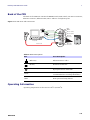
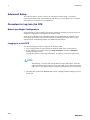
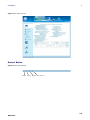
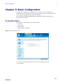
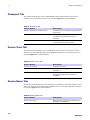
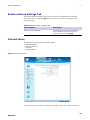
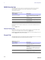
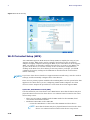
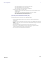
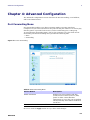
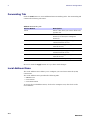
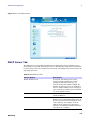
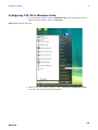
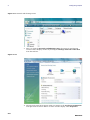
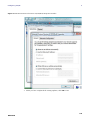
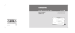
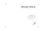
CPEi 885
Series
User Manual
Table
of
Contents
Contents
Chapter 1: Desktop CPEi 885 User Guide
Overview . . . . . . . . . . . . . . . . . . . .
Powerful Features in a Single Unit
Front of the CPE . . . . . . . . . . . . . . .
Back of the CPE . . . . . . . . . . . . . . .
Operating Information . . . . . . . . . .
..
..
..
..
..
..
..
..
..
..
........................................
........................................
........................................
........................................
........................................
1-1
1-2
1-2
1-3
1-3
Chapter 2: Installation
Overview . . . . . . . . . . . . . . . . . . . . . . . . . . . . . . . . . . . . . . . . . . . . . . . . . . . . . . . . . . . . . .
Before you Begin . . . . . . . . . . . . . . . . . . . . . . . . . . . . . . . . . . . . . . . . . . . . . . . . . . . . . . . .
Easy Setup . . . . . . . . . . . . . . . . . . . . . . . . . . . . . . . . . . . . . . . . . . . . . . . . . . . . . . . . . . . . .
Advanced Setup . . . . . . . . . . . . . . . . . . . . . . . . . . . . . . . . . . . . . . . . . . . . . . . . . . . . . . . . .
Procedure to Log into the CPE . . . . . . . . . . . . . . . . . . . . . . . . . . . . . . . . . . . . . . . . . . . . . .
Setup Wizard and Authentication . . . . . . . . . . . . . . . . . . . . . . . . . . . . . . . . . . . . . . . . . . .
.
.
.
.
.
.
.
.
.
.
.
.
2-1
2-1
2-1
2-2
2-2
2-3
Chapter 3: Basic Configuration
Personalize Menu . . . . . . . . . . . . . . . . . . . . . . . . . . . . . . . . . . . . . . . . . . . . . . . . . . . . . . . .
Password Tab . . . . . . . . . . . . . . . . . . . . . . . . . . . . . . . . . . . . . . . . . . . . . . . . . . . . . . . . . . .
Device Time Tab . . . . . . . . . . . . . . . . . . . . . . . . . . . . . . . . . . . . . . . . . . . . . . . . . . . . . . . . .
Device Name Tab . . . . . . . . . . . . . . . . . . . . . . . . . . . . . . . . . . . . . . . . . . . . . . . . . . . . . . . .
Restore Factory Settings Tab . . . . . . . . . . . . . . . . . . . . . . . . . . . . . . . . . . . . . . . . . . . . . . .
Internet Menu . . . . . . . . . . . . . . . . . . . . . . . . . . . . . . . . . . . . . . . . . . . . . . . . . . . . . . . . . .
WiMAX Security Tab . . . . . . . . . . . . . . . . . . . . . . . . . . . . . . . . . . . . . . . . . . . . . . . . . . . . .
Firewall Tab . . . . . . . . . . . . . . . . . . . . . . . . . . . . . . . . . . . . . . . . . . . . . . . . . . . . . . . . . . . .
Dynamic DNS Tab . . . . . . . . . . . . . . . . . . . . . . . . . . . . . . . . . . . . . . . . . . . . . . . . . . . . . . .
Status Menu . . . . . . . . . . . . . . . . . . . . . . . . . . . . . . . . . . . . . . . . . . . . . . . . . . . . . . . . . . . .
Telephony Menu . . . . . . . . . . . . . . . . . . . . . . . . . . . . . . . . . . . . . . . . . . . . . . . . . . . . . . . . .
Wi-Fi . . . . . . . . . . . . . . . . . . . . . . . . . . . . . . . . . . . . . . . . . . . . . . . . . . . . . . . . . . . . . . . . . .
Wi-Fi Menu . . . . . . . . . . . . . . . . . . . . . . . . . . . . . . . . . . . . . . . . . . . . . . . . . . . . . . . . . . . . .
. . 3-1
. . 3-2
. . 3-2
. . 3-2
. . 3-3
. . 3-3
. . 3-4
. . 3-4
. . 3-5
. . 3-5
. . 3-6
. 3-13
. 3-13
Chapter 4: Advanced Configuration
Port Forwarding Menu . . . . . . . . . . . . . . . . . . . . . . . . . . . . . . . . . . . . . . . . . . . . . . . . . . . . . .
Forwarding Tab . . . . . . . . . . . . . . . . . . . . . . . . . . . . . . . . . . . . . . . . . . . . . . . . . . . . . . . . . . .
Local Address Menu . . . . . . . . . . . . . . . . . . . . . . . . . . . . . . . . . . . . . . . . . . . . . . . . . . . . . . . .
DHCP Server Tab . . . . . . . . . . . . . . . . . . . . . . . . . . . . . . . . . . . . . . . . . . . . . . . . . . . . . . . . . .
Lease Status Tab . . . . . . . . . . . . . . . . . . . . . . . . . . . . . . . . . . . . . . . . . . . . . . . . . . . . . . . . . .
Lease Reservation Tab . . . . . . . . . . . . . . . . . . . . . . . . . . . . . . . . . . . . . . . . . . . . . . . . . . . . . .
Control Panel . . . . . . . . . . . . . . . . . . . . . . . . . . . . . . . . . . . . . . . . . . . . . . . . . . . . . . . . . . . . .
Software Tab . . . . . . . . . . . . . . . . . . . . . . . . . . . . . . . . . . . . . . . . . . . . . . . . . . . . . . . . . . . . .
4-1
4-2
4-2
4-3
4-4
4-4
4-5
4-6
i
DEC 2010
Certificate Tab .
System Tab . . . .
About Tab . . . . .
Wi-Fi Advanced
.
.
.
.
.
.
.
.
.
.
.
.
.
.
.
.
.
.
.
.
.
.
.
.
.
.
.
.
.
.
.
.
.
.
.
.
.
.
.
.
.
.
.
.
.
.
.
.
.
.
.
.
.
.
.
.
.
.
.
.
.
.
.
.
.
.
.
.
.
.
.
.
.
.
.
.
.
.
.
.
...................................
...................................
...................................
...................................
.
.
.
.
.
.
.
.
.
.
.
.
.
.
.
.
4-6
4-6
4-7
4-7
Chapter 5: Configuring TCP/IP
Configuring TCP/IP in Windows XP . . . . . . . . . . . . . . . . . . . . . . . . . . . . . . . . . . . . . . . . . . . . 5-1
Configuring TCP/IP in Windows Vista . . . . . . . . . . . . . . . . . . . . . . . . . . . . . . . . . . . . . . . . . . 5-5
Chapter 6: Troubleshooting
Power . . . . . . . . . . . . . . . . . . . . . . . . . .
A Computer Cannot Log On to the CPE
Cannot Connect to the Internet . . . . . .
Additional Troubleshooting Help . . . . .
.
.
.
.
.
.
.
.
...
...
...
...
...............................
...............................
...............................
...............................
Chapter 7: Important Safety and Legal Information
..
..
..
..
.
.
.
.
.
.
.
.
.
.
.
.
6-1
6-1
6-1
6-1
. . . . . . . . . . . . . . . . . . . . . . . . 7-1
ii
DEC 2010
Desktop CPEi 885 User Guide
1
Chapter 1: Desktop CPEi 885 User Guide
Overview
Thank you for purchasing the Motorola CPE Indoor CPEi 885 desktop device. The
Desktop CPEi 885 allows you to connect to the wireless world easily and seamlessly
without complicated installation and setup procedures. In addition, it offers you the
ability to make Voice over Internet Protocol (VoIP) calls.
The Desktop CPE indoor CPEi 885 device provides the user:
• Convenience - with easy plug and play functionality. Compact design.
• Control - remote management capability allows easy detection and authentication
once the unit is set up.
• VoIP - two RJ11 ports allow for Voice over IP calls using your CPEi 885.
• Wi-Fi - wireless LAN
The features and the physical appearance of your Desktop CPEi 885 device may differ
slightly from the illustration.
Figure 1-1: CPEi 885
For the most recent documentation, visit the Product Documentation page on
www.motorola.com/wimaxmanuals.
1-1
DEC 2010
1
Desktop CPEi 885 User Guide
Powerful Features in a Single Unit
The CPE device provides the following features:
• WiMAX Authentication
• WAN DHCP Client
• LAN DHCP Server
• Home Gateway Functions
• Firewall Protection
• Port Forwarding
• Wi-Fi
Front of the CPE
The front of the CPE unit contains LED Link/Activity indicators. The LEDs show the
status of the initialization during and network connections during power up. The LEDs
also indicate the signal strength, and if Wi-Fi is enabled.
Table 1-1 LED Indicator Interface
LED
Status
(W i-Fi)
Indicates if Wi-Fi is enabled or disabled.
LED on, Wi-Fi is enabled.
(Signal Strength)
Full WiMAX Signal Strength is detected
when all WiMAX Signal Strength LEDs are
lit.
• One to two WiMAX Signal Strength
LEDs are lit - low signal detected.
• Three to five WiMAX Signal Strength
LEDs are lit - high signal detected.
(WiMAX Status)
While acquiring access to the WiMAX
Network:
• All WiMAX Signal Strength LEDs vary
between ON, OFF and/or BLINKING
status.
(VoIP Status)
Indicates the status of the VoIP connection.
(LAN Status)
Indicates the status of the Ethernet
connection and activity
(Power)
Indicates if the device is powered or not.
1/2
1/2
1-2
DEC 2010
Desktop CPEi 885 User Guide
1
Back of the CPE
The back of the CPE unit contains the RESET switch, WPS switch, DC Power Connector,
Ethernet connector, Ethernet LED, Line 1 and Line 2 telephone ports.
Figure 1-2: CPE Ports and Connections
Telephone Cable
WPS
RESET
6
Phone 1 (VoIP)
Phone 2 (VoIP)
4
Telephone Cable
5
1
Computer
Ethernet Cable
Ethernet
Connector
2
CPEi 885
Power Cord
3
DC Power
Connector
CPEi 885
Table 1-2 Port Descriptions
Port
Port Description
(Ethernet)
Ethernet Ports 1 and 2.
(Power)
DC Power Connector.
(Phone Line)
RJ-11 ports for use with VoIP.
Reset
Hardware Reset Button (A paperclip is
recommended for accessing this button).
WPS
Wi-Fi pretected setup button.
Operating Information
Operating temperature for this unit is 0-40°C (32-104°F).
1-3
DEC 2010
1
Desktop CPEi 885 User Guide
This page intentionally left blank.
1-4
DEC 2010
Installation
2
Chapter 2: Installation
Overview
To install the Desktop CPEi 885 Series, review the following sections:
• Before You Begin
• Easy Setup
Before you Begin
Before you begin installation, check that you have received the following items with
your Desktop CPEi 885:
Table 2-1 In the box with your CPE, you should have
Item
Description
AC Power Adapter
Power adapter cord connects the Desktop
CPE to an AC electrical outlet.
Ethernet Cable
The Ethernet cable connects the Internet
port on your Desktop CPE to your PC or
laptop computer.
Desktop CPEi 885 Quick Start Guide
Desktop CPEi 885 Quick Start Guide
In addition, you need:
• A computer
• An RJ-11 telephone cable (optional). Two RJ-11 telephone cables are required if
your service provider has supplied you with two telephone numbers.
Easy Setup
The CPE is easily set up in your home. Basic installation equipment needed are the
power adapter, Ethernet cable, a PC or laptop computer and the CPE device.
If you want to use the VoIP functionality, you need an RJ-11 phone cable and a
telephone.
Perform the following tasks before attaching the power cord or powering up the unit:
• Stand the CPE on a flat surface.
• Plug the AC power adapter cord into an AC outlet.
• Plug one end of the Ethernet cable into the Ethernet connector on the back of the
unit.
• Plug the other end of the Ethernet cable into the Ethernet connector of your
computer.
• To use VoIP functionality of the phone, plug one end of the phone line into the
activated phone connector on the back of the unit. Phone line activation is
dependent upon your service contract.
• Plug the other end of the phone line into the phone line connector of your
telephone.
2-1
DEC 2010
2
Installation
Advanced Setup
The CPE can also be used to connect to a multi-port switch (hub) - purchased
separately from the CPE. Connecting the CPE device to a hub allows you to connect
more than one computer to your CPE device.
Procedure to Log into the CPE
Before you Begin Configuration
Some settings on your computer need to be verified or changed to ensure that your
computer configuration can support the Desktop CPE.
Verify that the IP addresses and DNS settings are automatically generated in your
Local Area connection of your Internet Protocol (TCP/IP) properties. Refer to the
chapter titled “Configuring TCP/IP” for additional information.
Logging in to the CPE
Use the following procedure to log into the Desktop CPE:
1. On a computer that is connected to the Desktop CPE, open a web browser.
2. In the Address or Location field, type http://mywimax. and press ENTER to
display the login screen.
Include the period (.) after http://mywimax. in order to access the login screen.
NOTE
Alternatively, you may enter the IP address: http://192.168.15.1 into the
address field in order to gain access to your CPE. If you cannot access the
CPE, refer to the chapter titled: Configuring TCP/IP for more information.
3.
The Welcome to Motorola WiMAX CPE screen is displayed and prompts you for a
password.
2-2
DEC 2010
Installation
2
Figure 2-1: Login Screen
4.
5.
6.
7.
In the Password field, type the password (default is motorola).
Click Login.
First time users see a pop-up box that states: “The Wizard application will guide
you through for the first time configuration”. Click OK button to continue.
Click the OK button to launch the wizard application.
Setup Wizard and Authentication
Step 1 - Change Password
Once you have launched the setup wizard, you are prompted to change your password.
Motorola recommends using a password to protect your home network and CPE
device. Passwords are case sensitive.
To change your password:
• Ensure the “Enable Login Password Protection” box is checked.
• Enter a New Login Password in the box. Passwords can be no more than 20
characters in length.
• Re-type your new password in the Confirm New Login Password box.
• Click Next.
If you forget your password, you can reset it back to the default (motorola) password.
To reset the password, press and hold the reset button on the back of your CPE for 5 or
more seconds. Before resetting the CPE, ensure that the power is ON.
Step 2 - Device Time
This screen allows you to set the time zone and to enable Daylight Savings Time (when
applicable) for your location.
• Select the appropriate time zone for your location from the drop-down box.
2-3
DEC 2010
2
Installation
•
•
Check the box that is called “Auto Adjust for Daylight Savings Time” if you live in a
region that observes Daylight Savings Time. This box is checked by default.
Click the Next button.
Step 3 - WiMAX Security
The WiMAX Security tab contains your authentication method. Check with your
service provider to determine if they require a user name and password for
authentication purposes.
• If the Authentication Method is EAP-TLS, no User Name and Password are
required. Enter the Realm information supplied by your service provider. Click the
Next button.
• If the Authentication Method is EAP-TTLS/MS-CHAPv2, enter a User Name and
Password, and Realm information supplied by your Service Provider. Once you have
entered the User Name/Password/Realm information, click the Next button.
• If you are unsure of the Authentication Method, select EAP-TLS (which is the
default) and click the Next button.
Step 4 - Account
The Account tab allows you to manage Voice over IP (VoIP) related services. Please
consult with your telephony service provider for these settings.
Click the Apply button when finished.
Congratulations! You have now completed the setup of your WiMAX connection.
Click OK on the Congratulations! dialog box.
A status screen appears that shows Network status and telephony status. The Network
Status screen provides any status associated with your WiMAX Wireless Broadband
connection. The Telephony Status screen provides status of your telephony service.
• The Restart button is used to restart the device. The restart button is available on
every screen.
• The Wizard button starts the set-up wizard over again.
• The Refresh button refreshes the screen with the current status.
• The Auto Refresh button allows the web browser to automatically refresh at the
interval determined in the Control Panel menu.
2-4
DEC 2010
Installation
2
Figure 2-2: Status Screen
Restart Button
Figure 2-3: Restart Button
Restart
Wizard
Refresh
Auto Refresh
2-5
DEC 2010
2
Installation
This page intentionally left blank.
2-6
DEC 2010
Basic Configuration
3
Chapter 3: Basic Configuration
Once the CPE setup has been completed, you can log in to your CPE from any
computer on your home network. To log in type the device name in the address bar on
your computer. The default device name is mywimax.
This section describes the PERSONALIZE, INTERNET, STATUS, and Wi-Fi basic
Menus that are available.
Personalize Menu
The Personalize menu provides the following tabs:
• Password
• Device Time
• Device Name
• Restore Factory Settings
Figure 3-1: Personalize Menu
To Access the Personalize menu, click on the Tools symbol, then click
on Personalize.
3-1
DEC 2010
3
Basic Configuration
Password Tab
The password tab allows you to enable/disable password protection. You can also
change your password here. Be sure to click the Apply button when finished
.
Table 3-1 Password Tab
Field or Button
Description
Enable Login Password Protection
Checking this box requires login password
protection.
New Login Password
Enter your new password here. Maximum
20 characters. Passwords are case
sensitive.
Confirm New Login Password
Re-enter your new password here, exactly
as entered in the previous step.
Device Time Tab
The Device Time tab allows you to establish the time zone for your location. It also
allows you to automatically adjust for Daylight Savings Time if necessary. Be sure to
click the Apply button when finished.
Table 3-2 Device Time Tab
Field or Button
Description
Current Local Time
Current Local Time
Time Zone
Select your local time zone from the dropdown box.
Auto Adjust for Daylight Saving Time
Check this box if your location observes
Daylight Savings Time. (Default is
checked)
Device Name Tab
The Device Name tab allows you to rename your CPE device. The Device Name is the
name you enter on an internet browser address bar to access your CPE device. Be sure
to click the Apply button when finished.
Table 3-3 Device Name Tab
Field or Button
Description
New Device Name
Enter the new name for the CPE device.
Maximum 20 characters.
3-2
DEC 2010
Basic Configuration
3
Restore Factory Settings Tab
The Restore Factory Settings Tab resets your CPE to the manufacturers default
settings. Be sure to click the Apply button if you are sure that you want to reset
factory settings.
Table 3-4 Restore Factory Settings Tab
Field or Button
Description
Restore Factory Settings
Checking this box restores the CPE to
factory default settings. The device
restarts when you click Apply.
Internet Menu
The Internet menu provides the following tabs:
• WiMAX Security
• Internet Protocol
• Firewall
• Dynamic DNS
Figure 3-2: Internet Menu
To access the Internet menu, click on the Computer icon, then click on Internet.
3-3
DEC 2010
3
Basic Configuration
WiMAX Security Tab
The WiMAX Security tab contains your authentication method. Check with your
service provider to determine a user name and password are required for
authentication purposes.
Table 3-5 WiMAX Security Tab
Field or Button
Description
Authentication Method
Drop down box allows you to select either
EAP-TLS (default) or EAP-TTLS/MSCHAPv2.
User Name (EAP-TTLS/MS-CHAPv2 only) Enter the User Name supplied by your
service provider.
Password (EAP-TTLS/MS-CHAPv2 only)
Enter the Password supplied by your
service provider.
Realm
Supplied by your service provider.
If your authentication method is EAP-TLS, then a User Name and Password are not
necessary.
Click the Apply button.
Internet Protocol Tab
Please check with your service provider for these settings. If you are unsure of the
settings, leave the default values set and click the Apply button.
If your service provider has instructed you to change any of these settings, be sure to
click the Apply button when you are finished.
Firewall Tab
A firewall helps to protect your home network from unauthorized access. It also helps
to manage authorized access from the internet to your CPE.
Table 3-6 Firewall Tab
Field or Button
Description
Enable Firewall
Check this box to enable the firewall for
your home network.
Enable Web Login from Internet
(Grayed out if Enable Firewall is not
selected).
Check this box to enables you to access
your CPE device from a network other
than your own.
Web Login Port from Internet
Choose a port number to connect to when
logging in from a network other than your
own. The default is 8080.
3-4
DEC 2010
Basic Configuration
3
Table 3-6 Firewall Tab
Field or Button
Description
Enable ping from Internet
Enables the CPE to respond to a ping from
the Internet. This option would be enabled
to allow testing only. Do not leave this
enabled.
Be sure to click the Apply button once you are finished.
Dynamic DNS Tab
Dynamic Domain Name Service (DDNS) allows a user with a non-static IP address to
keep their domain name associated with an ever changing IP address. As an example,
DDNS is used when you are hosting your own website.
Table 3-7 Dynamic DNS Tab
Field or Button
Description
Enable DDNS
Check this box to Enable DDNS (default is
unchecked).
DDNS Service Provider
Select DDNS Service Provider that you
belong to from the drop-down box.
DDNS User Name
Only valid if Enable DDNS is checked.
Enter your DDNS account user name.
DDNS Password
Only valid if Enable DDNS is checked.
Enter your DDNS account password.
DDNS Host Name
Only valid if Enable DDNS is checked.
Enter the DDNS Host Name. This is
assigned by the DDNS service.
Be sure to click the Apply button once you are finished.
Status Menu
The Status menu provides the following tabs:
• Network
• Telephony
3-5
DEC 2010
3
Basic Configuration
Figure 3-3: Status Menu
Network Tab
The Network tab provides any status associated with your WiMAX Wireless Broadband
connection.
Telephony Tab
The Telephony tab provides any status associated with your telephony connection.
Telephony Menu
The telephony menu allows you to manage your Voice over Internet Protocol (VoIP)
services.
NOTE
Contact your service provider to obtain VoIP service, if you do not already
have this service.
The Telephony menu provides the following tabs:
• Account
• Ring Tone
• Caller ID
• Call Forwarding
• Voice Mail
• Special Numbers
3-6
DEC 2010
Basic Configuration
3
Figure 3-4: Telephony Menu
Account Tab
Please consult with your service provider for these settings. The Account Tab contains
the following settings:
Table 3-8 Account Tab
Field or Button
Description
Line 1 User Name
If Line 1 is an active VoIP, enter the User
Name as provided by your service
provider.
Line 1 Password
Enter the Line 1 password as provided by
your service provider. Passwords are case
sensitive.
Confirm Line 1 Password
Reenter your Line 1 password exactly as
entered in the field from the previous
step.
Line 2 User Name
If Line 2 is an active VoIP, enter the User
Name as provided by your service
provider.
Line 2 Password
Enter the Line 2 password as provided by
your service provider. Passwords are case
sensitive.
Confirm Line 2 Password
Re-enter your Line 2 password exactly as
entered in the field from the previous
step.
Be sure to click the Apply button once you have made changes.
3-7
DEC 2010
3
Basic Configuration
NOTE
Support for the following VoIP features is dependent upon your
service contract.
Ring Tone Tab
The Ring Tone tab allows you to customize ring tones for your telephone(s).
NOTE
You need a phone connected to your CPE to hear ring tones.
Table 3-9 Ring Tone Tab
Field or Button
Description
Default Line 1 Ring Type
Use the drop-down box to select a ring
tone for Line 1. The default is ringtone R0.
Test
Click to hear how the selected ring tone
sounds.
Default Line 2 Ring Type
Use the drop-down box to select a ring
tone for Line 2. The default is ringtone R0.
Test
Click to hear how the selected ring tone
sounds.
Be sure to click the Apply button once you have made changes.
Caller ID Tab
The Caller ID tab allows you to manage the Caller ID functions for your telephones:
Table 3-10 Caller ID Tab
Field or Button
Description
Enable Line 1 Anonymous Incoming Call
Rejection
If Line 1 is your active telephone port,
check this box if you would like to reject
telephone calls from anonymous incoming
callers. The default is checked.
Enable Line 1 Permanent Anonymous
Outgoing Call
If Line 1 is your active telephone port,
check this box if you would like to
permanently block your telephone number
from appearing on others’ Caller ID. The
default is unchecked.
Enable Line 2 Anonymous Incoming Call
Rejection
If Line 2 is your active telephone port,
check this box if you would like to reject
telephone calls from anonymous incoming
callers. The default is checked.
3-8
DEC 2010
Basic Configuration
3
Table 3-10 Caller ID Tab
Field or Button
Description
Enable Line 2 Permanent Anonymous
Outgoing Call
If Line 2 is your active telephone port,
check this box if you would like to
permanently block your telephone number
from appearing on others’ Caller ID. The
default is unchecked.
Be sure to click the Apply button once you have made changes.
Call Forwarding Tab
The Call Forwarding tab allows you to manage the call forwarding features for your
telephone(s). The Call Forwarding tab contains the following:
Table 3-11 Call Forwarding Tab
Field or Button
Description
Enable Line 1 Basic Forwarding
Check this box to enable basic call
forwarding on Line 1. The default is
unchecked.
Line 1 Basic Forwarding to Number
If “Enable Line 1 Basic Forwarding” is
checked, enter the telephone number you
would like to forward calls to.
Enable Line 1 Forwarding on No Answer
Check this box to forward calls received
on Line 1 if there is no answer. This
function is not available if “Enable Line 1
Basic Forwarding” is checked.
Line 1 No Answer Forwarding to Number If “Line 1 No Answer Forwarding to
Number” is checked, enter the telephone
number you would like to forward calls to
when there is no answer on Line 1. This
function is not available if “Enable Line 1
Basic Forwarding” is checked.
Line 1 No Answer Forwarding Ring Count Enter the number of rings allowed before
the call forwards to the number identified
above. The default is six rings.
Enable Line 1 Forwarding on Busy
Check this box to forward calls received
while Line 1 is in use.
Line 1 Busy Forwarding To Number
If “Enable Line 1 Forwarding on Busy” is
checked, enter the telephone number you
would like calls forwarded to when Line 1
is in use.
Enable Line 2 Basic Forwarding
Check this box to enable basic call
forwarding on Line 2. The default is
unchecked.
Line 2 Basic Forwarding to Number
If “Enable Line 2 Basic Forwarding” is
checked, enter the telephone number you
would like to forward calls to.
3-9
DEC 2010
3
Basic Configuration
Table 3-11 Call Forwarding Tab
Field or Button
Description
Enable Line 2 Forwarding on No Answer
Check this box to forward calls received
on Line 2 if there is no answer. This
function is not available if “Enable Line 2
Basic Forwarding” is checked.
Line 2 No Answer Forwarding to Number If “Line 2 No Answer Forwarding to
Number” is checked, enter the telephone
number you would like to forward calls to
when there is no answer on Line 2. This
function is not available if “Enable Line 2
Basic Forwarding” is checked.
Line 2 No Answer Forwarding Ring Count Enter the number of rings allowed before
the call forwards to the number identified
above. The default is six rings.
Enable Line 2 Forwarding on Busy
Check this box to forward calls received
while Line 2 is in use.
Line 2 Busy Forwarding To Number
If “Enable Line 2 Forwarding on Busy” is
checked, enter the telephone number you
would like calls forwarded to when Line 2
is in use.
Be sure to click the Apply button once you have made changes.
Voice Mail Tab
The voice mail tab allows you to see the status of your voice mail.
Please contact your service provider to activate the voice mail feature if it is not
already active. The Voice Mail Tab contains the following:
Table 3-12 Voice Mail Tab
Field or Button
Description
Line 1 Server Based Voice Mail Status
Shows the status of Line 1 voice mail as
either enabled or disabled.
Line 1 Number of New Voice Mails
Shows the number of new, unheard voice
mails on Line 1.
Line 1 Number of Old Voice Mails
Shows the number of previously heard
voice mails on Line 1.
Line 2 Server Based Voice Mail Status
Shows the status of Line 2 voice mail as
either enabled or disabled.
Line 2 Number of New Voice Mails
Shows the number of new, unheard voice
mails on Line 2.
Line 2 Number of Old Voice Mails
Shows the number of previously heard
voice mails on Line 2.
Be sure to click the Apply button once you have made changes.
3-10
DEC 2010
Basic Configuration
3
Special Number Tab
The Special Number tab provides a list of special dialing numbers for your VoIP Phone
Service. The Special Number Tab contains the following:
Table 3-13 Special Number Tab
Field or Button
Description
Service Provider Contact Number
Use this number to contact customer
service for your service provider.
Emergency Number
Dial this number to reach local emergency
services.
Redial
Dial this number to redial the last number
called.
Blind Call Transfer
Dial this number to transfer a call directly
to a third party.
Consultation Call Transfer
Dial this number to speak with the third
party before you transfer the call to them.
Call Hold
Dial this number to place your current call
on hold.
Automatic Recall Activate
Dial this number to call back the number
of the last incoming call.
Automatic Recall Deactivate
Dial this number to automatically call
back the last number dialed when that
number becomes available.
Call Forwarding Activate
Dial this number to forward your calls to a
different number.
Call Forwarding Deactivate
Dial this number to deactivate call
forwarding.
Call Forwarding Busy Activate
Dial this number to forward calls to a
different number when the line is busy.
Call Forwarding Busy Deactivate
Dial this number to de-activate calls from
forwarding to a different number when
the line is busy.
Call Forwarding Busy Change Number
Dial this number to change the phone
number to which calls will be forwarded
when the line is busy.
Call Forwarding No Answer Activate
Dial this number to forward calls to a
different number when there is no answer
on Line 1 or Line 2.
Call Forwarding No Answer Deactivate
Dial this number to de-activate calls from
forwarding to a different number when
there is no answer on Line 1 or Line 2.
Call Forwarding No Answer Change
Number
Dial this number to change the phone
number to which calls will be forwarded
when there is no answer on Line 1 or Line
2.
3-11
DEC 2010
3
Basic Configuration
Table 3-13 Special Number Tab
Field or Button
Description
Automatic Callback Activate
Dial this number to hear the most recent
call you missed and to return the call. If
the number is busy, you can hang up.
When the number is available, your phone
will ring. Pick up your phone and the call
will be connected.
Automatic Callback Deactivate
Dial this number to de-activate automatic
callback.
Do Not Disturb Activate
Dial this number to have calls
automatically routed to voice mail.
Do Not Disturb Deactivate
Dial this number to cancel automatic call
routing to voice mail.
Calling Number Delivery Blocking
Dial this number to block your number
from appearing on the Caller ID of the
people you call. Your calls may appear as
Private or Anonymous.
Line Blocking Deactivate
Dial this number to unblock your
telephone number from appearing on
Caller ID.
Call Waiting Toggle
Dial this number to toggle between call
waiting ON and call waiting OFF.
Anonymous Call Rejection Activate
Dial this number to have anonymous calls
rejected.
Anonymous Call Rejection Deactivate
Dial this number to allow anonymous calls
to go through.
3-12
DEC 2010
Basic Configuration
3
Wi-Fi
The Wi-Fi basic menu helps manage the Wi-Fi related configurations. This menu
includes Basic, and Security menus. For the Advanced settings, refer to the Advanced
Configuration chapter “Wi-Fi Advanced” on page 4 - 7.
Figure 3-5: Wi-Fi Basic Menu
Wi-Fi Menu
Wi-Fi Basic (Wireless LAN) network settings are configured at this menu which
includes:
Table 3-14 Wi-Fi Basic
Field or Button
Description
Enable Wi-Fi Wireless Service
Enable Wi-Fi service of the device by clicking the box
to place a check mark. This function is disabled by
clicking the box to remove the check mark.
Wi-Fi Network SSID
Network Service Set Identifier (SSID) is a label/name
that distinguishes one wireless LAN (Wi-Fi network)
from another. The field is case-sensitive and must not
exceed 32 characters. For added security, changing
the default SSID (Wi-Fi) to a unique name is
recommended.
To access the Wi-Fi menu, click on the Wi-Fi icon, then click on Wi-Fi.
3-13
DEC 2010
3
Basic Configuration
Table 3-14 Wi-Fi Basic
Field or Button
Description
Operating Mode
A pull-down list with the choices of:
• 802.11b only (default)
• 802.11g only
• 802.11b/g
• 802.11n
Select 802.11 b/g to set the device to operate the WiFi network with both 802.11b and 802.11g wireless
devices.
Operating Channels
A pull-down list with choices from one to fourteen (1
through 14) depending upon the country/region
setting. The default range is one to eleven (1 through
11). The default channel is six (6).
The Wi-FI operating mode channel settings can be
modified if there are problems with nearby wireless
devices.
The operating channel selection is as follows:
• 1 - 11: United States, Canada, and other
• 1 - 13: Europe, Australia, Venezuela
• 1 - 14: Japan (channels 1 - 14 if selecting 802.11b,
channels 1 - 13 if 802.11b/g or 802.11g is
selected)
• 3 - 9: Israel
Wi-Fi Security
The Wi-Fi Security menu enables you to choose the wireless LAN security protocol to
enable authentication and secure data transmission on the Wi-Fi network.
NOTE
• Make sure the selected network security protocol is supported by the wireless
devices on the network.
• Wi-Fi security is disabled by default. Use this Wi-Fi Security menu to manually
enable Wi-Fi security.
3-14
DEC 2010
Basic Configuration
3
WEP Configuration
Table 3-15 WEP Configuration
Field or Button
Description
Authentication Type
A pull-down list with choices of:
• Automatic
• Shared
• Open
The default is Automatic. Two methods of authentication can
be used with WEP: Open System authentication and Shared
Key authentication. Choose Automatic to allow the device to
automatically switch to the WEP authentication type used by
the wireless device entering the network.
Encryption Strength
A pull-down list with choices of 64-bits Key and 128-bits Key.
The default is 64-bits Key. Data transmission on the Wireless
LAN is encrypted when WEP is enabled. Data encryption key
is either 64bits or 128 bits.
Passphrase
Choices for the passphrase are:
• Key Index - pull down menu lets you choose the type of key
generation.
• Automatic Key Generation - this feature generates 4 keys
where one can be chosen to for use as the network
security passphrase. Click the Generate Key button.
If a 64-bit encryption key is used, enter 10 hexadecimal digits
(any combination of 0-9, a-f, or A-F). 128-bit WEP encryption
key, enter 26 hexadecimal digits (any combination of 0-9, a-f,
A-F).
WPA/WPA2 Configuration
Manage WPA/WPA2 security protocol settings. Underneath WPA/WPA2 Configuration.
Table 3-16 WPA/WPA2 Menu Selections
Field or Button
Description
Group Key Renewal
This setting determines how often the group key is going to
change. The group key renewal interval range is 300 to 7200.
Default setting is 3600 seconds.
Security Type
Authentication keys can be generated either automatically or
entered manually. The types of authentication selections are:
• Remote (Radius) - Radius Server IP address where the
field is broken into 4 sub-fields with each limited to 3 digits
and the default is empty.
• Shared (local) - a preshared key that includes the PSK
passphrase where the default is an empty field.
3-15
DEC 2010
3
Basic Configuration
Figure 3-5: Wi-Fi Security
Wi-Fi Protected Setup (WPS)
Your CPEi 885 supports Wi-Fi Protected Setup (WPS) to simplify the setup of your
wireless security. WPS can be used to configure client devices such as wireless
adapters in laptop computers that support WPS. If your client devices do not support
WPS, you will have to manually configure those devices. In order to use WPS to set
up your client devices, access the security section of the Wi-Fi configuration by
clicking on the Wi-Fi icon, then clicking on Security. Before you begin, you should
configure the security settings in the CPEi 885 as described in the section above
before continuing.
NOTE
If you have client devices that do not support Wi-Fi Protected Setup, note the wireless
settings, and then manually configure those client devices.
There are two primary options available when utilizing WPS. Use the option below that
applies to the client device you are configuring. NOTE: WPS configures one client
device at a time. Repeat the procedure for each client device that supports WPS.
Option #1, Push Button Control (PBC)
Use this method if your client device has a WPS button. Note that the button may be a
physical button located on the client device or a software button located on the client
device setup screen.
•
•
There are two options available with the PBC method on the CPEi885, hard
ware button and software button.
Hardware button PBC on the CPEi 885
- Locate the WPS button on the back of the CPEi885 and client device.
NOTE
Note that the button may be a physical button located on the client
device or a software button located on the device setup screen.
3-16
DEC 2010
Basic Configuration
3
•
- Press the WPS button on the back of the CPEi 885.
- Press the WPS button on the client device.
- The connection will be automatically established.
Software button PBC on the CPEi 885
- Navigate to the Security page of the Wi-Fi section of the CPEi 885 GUI as
detailed above.
- Select “PBC” at the WPS Method dialog box and select “Apply”.
- Press the WPS button on the client device.
- The connection will be automatically established.
Option #2, Personal Identification Number (PIN)
Use this method if your client device has a WPS PIN number.
•
•
•
•
•
•
DEC 2010
Initiate the WPS PIN procedure on the client device per the manufacturer’s
instructions.
Navigate to the Security page of the Wi-Fi section of the CPEi885 GUI as detailed
above.
Make sure the “PIN” option is selected in the WPS Method dialog box in the Wi-Fi
Security Screen.
Enter the PIN number of the client device in the field on this screen.
Click “Apply” on the CPEi885 GUI screen. This must be completed within 2
minutes of starting the procedure on the client device.
The connection will be automatically established.
3-17
3
Basic Configuration
This page intentionally left blank.
3-18
DEC 2010
Advanced Configuration
4
Chapter 4: Advanced Configuration
The Advanced Configuration section describes the Port Forwarding, Local Address,
and Control Panel menus.
Port Forwarding Menu
Port forwarding enables you to direct incoming traffic to specific LAN hosts
(computers on your network) based on the protocol and port number. It is used to play
Internet games or provide local services (such as web hosting) for a LAN group.
To access the Port Forwarding manu, click on the Computer icon, then click on Port
Forwarding. The Port Forwarding menu provides the following tabs:
• Basic
• Forwarding
Figure 4-1: Port Forwarding
Table 4-1 Port Forwarding Menu
Field or Button
Description
Enable UPnP IGD
Enables the Universal Plug and Play
(UPnP) Internet Gateway Device (IGD)
profile to allow certain Windows
applications to set up the port forwarding
rule dynamically when NAT is enabled on
this device.
DMZ (DeMilitarized Zone) IP Address
Enter the DMZ IP Address.
Be sure to click the Apply button once you have made changes.
4-1
DEC 2010
4
Advanced Configuration
Forwarding Tab
Click the ADD button to create additional Port Forwarding rules. The Forwarding tab
contains the following selections:
Table 4-2 Forwarding Tab
Field or Button
Description
Select
Select a box when you want to delete the
specific row.
Protocol
Select TCP (Transmission Control
Protocol) or UDP (User Datagram
Protocol).
WAN Port Start
Enter the beginning port range for
external network access.
WAN Port End
Enter the ending port range for external
network access.
LAN IP Address
Enter the IP address to host the service.
LAN Port Start
Enter the beginning port range for
internal network access.
LAN Port End
Enter the ending port range for internal
network access.
Enabled
Check to enable specific port forwarding.
Be sure to click the Apply button once you have made changes.
Local Address Menu
The Local Address menu allows you to configure your Local Area Network (LAN)
connections.
The Local Address menu provides the following tabs:
• DHCP Server
• Lease Status
• Lease Reservation
To access the Local Address menu, click on the Computer icon, then click on the
Local Address.
4-2
DEC 2010
Advanced Configuration
4
Figure 4-2: Local Address Menu
DHCP Server Tab
The DHCP Server tab enables Dynamic Host Configuration Protocol (DHCP) server
functionality on the LAN, allowing the router to dynamically assign lease IP addresses
to clients that connect to it from the local network. The DHCP Server Tab contains the
following selections:
Table 4-3 DHCP Server Tab
Field or Button
Description
Enable DHCP Server
If selected, the DHCP server on the
gateway assigns IP addresses to the
computers and other hosts on your
network if they have DHCP enabled. By
default, the gateway server is enabled. If
there is another DHCP server running on
your network (on another router), disable
one of the DHCP servers.
DHCP Server IP Address
Enter the default port forwarding LAN
Client IP Address.
DHCP Starting IP Address
Sets the first IP address assigned by the
DHCP server, in dotted-decimal format. It
must be greater than the IP address value
of the gateway. For example, if the IP
address of the gateway is 192.168.15.1
(default), the starting IP address must be
192.168.15.2 (or higher).
4-3
DEC 2010
4
Advanced Configuration
Table 4-3 DHCP Server Tab
Field or Button
Description
DHCP Ending IP Address
Sets the final IP address assigned by the
DHCP server. If the DHCP server runs out
of DHCP addresses, users cannot access
network resources. If this happens,
increase the Ending IP or reduce the
Lease Time.
DHCP Lease Time
Sets the time, in seconds, that a network
computer remains connected to the
gateway using its current assigned IP
address. At the end of this time, the DHCP
server renews the lease or assigns the
computer a new IP address. The default is
3600 seconds (one hour). The maximum is
999999 seconds (about 278 hours).
Be sure to click the Apply button once you have made changes.
Lease Status Tab
The Lease Status tab in the Local Address menu displays the active DHCP leases since
the last reboot. The Lease Status Tab contains the following selections:
Table 4-4 Lease Status Tab
Field or Button
Description
Client Host Name
Displays the client host name. The Name
field is limited to 20 characters (only 5
appear in display).
MAC Address
Media Access Control (MAC) address.
IP Address
Shows the IP Address for each active
lease.
Remaining Lease Duration
Shows the amount of time, in seconds,
remaining in the lease.
Be sure to click the Apply button once you have made changes.
Lease Reservation Tab
This tab allows you to manage the lease reservation so that the same client receives
the same IP address each time. The Lease Reservation Tab contains the following
selections:
4-4
DEC 2010
Advanced Configuration
4
Table 4-5 Lease Reservation Tab
Field or Button
Description
Select
Select this box if you want to delete an
established lease reservation. Be sure to
click the Delete button once you have
selected the exception to be deleted.
Client Host Name
Enter the client host name. The Name
field is limited to 20 characters (only 5
appear in display)
MAC Address
Media Access Control (MAC) address.
Enter the MAC address of the device.
IP Address
Enter the IP address that you want
assigned to the MAC Address.
Enabled
Clicking this box enables the lease
reservation.
Be sure to click the Apply button once you have made changes.
Control Panel
The Control Panel sections allows you to view/update your software information.
The Control menu provides the following tabs:
• Software
• Certificate
• System
• About
4-5
DEC 2010
4
Advanced Configuration
Figure 4-3: Control Panel Menu
Software Tab
The Software tab manages the software on your CPE device. It is also where you can
upgrade device software.
Use the BROWSE button to browse your computer for additional software packages.
Once you have located the software package/update you would like to add to your
device, click the Upgrade button.
Select the software you would like to install and click the Install button.
If you would like to remove software, select the software package you would like to
remove and click Uninstall.
Certificate Tab
The Certificate tab is where you view the certificates that are stored on the device.
System Tab
This tab allows you to manage additional features of your CPE device.
4-6
DEC 2010
Advanced Configuration
4
Table 4-6 System Tab
Field or Button
Description
Language Used in User Interface
Select the desired language for the user
interface. The default language is English.
Enable WiMAX Radio Interface
Check this box to enable the WiMAX
Radio Interface.
Auto Refresh Interval
Enter, in seconds, the interval for status
Auto Refresh. Valid range is 2 seconds 9999 seconds. The default value is 3
seconds.
Background
Select the desired background color for the
user interface.
About Tab
The About Tab displays basic properties of your CPE device such as: Product Name,
Model ID, Hardware Version, Serial Number, and the WiMAX MAC Address.
Wi-Fi Advanced
The Wi-Fi Advanced menu provides the following field settings:
Table 4-7 Wi-Fi Advanced Menu
Field or Button
Description
Enable SSID broadcast
Check the box to disable the SSID of your wireless LAN network to be broadcast by the device. The wireless client on
the wireless LAN will have to know the SSID of the device in
order to connect to the network if this option is checked.
Transmit Rate
Select the basic transfer rates based on the speed of
wireless device on the wireless LAN. It is strongly
recommended to keep this setting to Auto.
Transmit Power
Set the transmit power level of the Wi-Fi radio. Available
options are low, medium and high.
4-7
DEC 2010
4
Advanced Configuration
Table 4-7 Wi-Fi Advanced Menu
Field or Button
Description
Beacon Interval
Enter a value between 1 and 65,535 milliseconds. The
Beacon Interval value indicates the frequency interval of the
beacon. A beacon is a packet broadcast by the device to
synchronize the other wireless network.
RTS Threshold
This value should remain at its default setting of 2347. The
range is 0-2347 bytes. Should you encounter inconsistent
data flow, only minor modifications are recommended. If a
network packet is smaller than the preset RTS threshold
size, the RTS/CTS mechanism will not be enabled. The
device sends Request to Send (RTS) frames to a particular
receiving wireless client on the network and negotiates the
sending of a data frame. After receiving an RTS, the
wireless client responds with a Clear to Send (CTS) frame to
acknowledge the right to begin transmission.
Preamble Type
The Preamble defines the length of the CRC block (Cyclic
Redundancy Check is a common technique for detecting
data transmission errors) for communication between the
wireless router and the roaming wireless network adapters.
Note: High network traffic areas should use the shorter
preamble type.
Fragmentation
Threshold
The range is 256-2346 bytes. It specifies the maximum size
for a packet before data is fragmented into multiple
packets. If you experience a high packet error rate, you may
slightly increase the Fragmentation Threshold. Setting the
Fragmentation Threshold too low may result in poor
network performance. Only minor modifications of this
value are recommended.
DTIM Interval
The default value is 3. This value, between 1 and 255
milliseconds, indicates the interval of the Delivery Traffic
Indication Message (DTIM). A DTIM field is a countdown
field informing clients of the next window for listening to
broadcast and multicast messages. When the router has
buffered broadcast or multicast messages for associated
clients, it
sends the next DTIM with a DTIM Interval value. Its clients
hear the beacons and awaken to receive the broadcast and
multicast messages.
CTS Protection Mode
CTS (Clear To Send) is a function used to minimize
collisions among wireless devices on a wireless LAN. CTS
will make sure the wireless network is clear before a
wireless client attempts to send wireless data. Enabling CTS
will add overhead and may lower wireless through put.
None: CTS is typically used in a pure 802.11g environment.
If CTS is set to “Disable” in a mixed mode environment
populated by 802.11b clients, wireless collisions may occur
frequently. If set to Enable, CTS will always be used to
make sure the wireless LAN is clear before sending data. If
set to Auto, CTS will monitor the wireless network and
automatically decide whether to implement CTS based on
the amount of traffic and collisions that occurs on the
wireless LAN.
4-8
DEC 2010
Advanced Configuration
4
Table 4-7 Wi-Fi Advanced Menu
Field or Button
Description
WMM
Wi-Fi Multimedia is QoS (Quality of Service) for the wireless
LAN. Enable this option to improve the quality of video and
voice applications for the wireless clients on the network.
Wireless Client Access
List
This option is to increase the wireless LAN network
security. If checked, only the wireless client with the MAC
address listed in the Wireless Client Access table can
connect to the wireless LAN.
4-9
DEC 2010
4
Advanced Configuration
This page intentionally left blank.
4-10
DEC 2010
Configuring TCP/IP
5
Chapter 5: Configuring TCP/IP
This section contains two examples of configuring TCP/IP in a Windows environment.
Most computers already have the TCP/IP configuration enabled. Use the following
procedures to verify that the configuration is set up. Configure all client computers on
your network for TCP/IP (the protocol that controls communication among computers).
Two examples are provided in this document:
• Configuring TCP/IP in Windows XP
• Configuring TCP/IP in Windows Vista
NOTE
Follow the instructions in your computer user manual for other Operating
Systems.
Configuring TCP/IP in Windows XP
1.
On the Windows desktop, click Start to display the Start window:
Figure 5-1: Windows XP Start Window
2.
Click Control Panel to display the Control Panel window. The display varies,
depending on your Windows XP view options. If the display is a Category view as
shown in Figure 5-2, continue with Step 3. Otherwise, skip to Step 5.
5-1
DEC 2010
5
Configuring TCP/IP
Figure 5-2: Control Panel
3.
Click Network and Internet Connections to display the Network and Internet
Connections window:
Figure 5-3: Network and Internet Connections
4.
5.
Click Network Connections. Skip to Step 6.
If a classic view like Figure 5-4 is displayed, double-click Network Connections
to display the LAN or High-speed Internet connections.
5-2
DEC 2010
Configuring TCP/IP
5
Figure 5-4: Control Panel Classic View
6.
Right-click the Local Area Connection. If more than one connection is displayed,
be sure to select the one for your network interface.
Figure 5-5: Network Connections
7.
Select Properties from the pop-up menu to display the Local Area Connection
Properties window:
5-3
DEC 2010
5
Configuring TCP/IP
Figure 5-6: Local Area Connection Properties
8.
9.
On the Local Area Connection Properties window, select Internet Protocol (TCP/
IP) if it is not selected.
Click Properties to display the Internet Protocol (TCP/IP) Properties window.
Figure 5-7: Internet Protocol (TCP/IP) Properties
10. Be sure Obtain IP address automatically and Obtain DNS server address
automatically are selected.
11. Click OK to close the TCP/IP Properties window.
5-4
DEC 2010
Configuring TCP/IP
5
Configuring TCP/IP in Windows Vista
1.
On the Windows desktop, click the Windows Logo on the left bottom corner to
display the Start window. Then click Network.
Figure 5-8: Network selection
2.
When the Network windows appears, click the Network and Sharing Center
from the action bar on the top of the window.
5-5
DEC 2010
5
Configuring TCP/IP
Figure 5-9: Network and Sharing Center
3.
After you click the Network and Sharing Center, the Network and Sharing
Center window displays. Follow by clicking the Manage Network Connection
from the task bar.
4.
The network connections appear. Drag your mouse to the Local Area Connection
and right click the mouse button. A series of tasks display. Click Properties.
Figure 5-10:
5-6
DEC 2010
Configuring TCP/IP
5
Figure 5-11: Local Area Connection selection
Figure 5-12: Properties selection
5.
A series of protocols appear. Among them, check the Internet Protocol Version
4 (TCP/IPv4) and click Properties.
5-7
DEC 2010
5
Configuring TCP/IP
Figure 5-13: Internet Protocol Version 4 (TCP/IPv4) properties selection
6.
At TCP/IPv4 Properties window, check Obtain an IP address automatically, and
Obtain DNS server address automatically. Click OK to save the settings.
5-8
DEC 2010
Configuring TCP/IP
5
Figure 5-14: Internet Protocol Version 4 (TCP/IPv4) Properties window
7.
When you have completed the setting updates, click OK to exit.
5-9
DEC 2010
5
Configuring TCP/IP
This page intentionally left blank.
5-10
DEC 2010
Troubleshooting
6
Chapter 6: Troubleshooting
Power
•
•
Check that the AC power adapter is properly plugged into the electrical outlet and
into the Desktop CPE.
Check that the electrical outlet is working.
A Computer Cannot Log On to the CPE
Check that the Ethernet cable is properly connected to the Desktop CPE unit and the
computer.
Cannot Connect to the Internet
•
•
Check the Desktop CPE connection status from the Web Interface, refer to the
Connection Status section to verify the connection status.
If the Desktop CPE connection is down, and the gateway has not received an IP for
5 minutes to 10 minutes:
- Re-Run the Setup Wizard.
- If the Setup Wizard does not help, then reset the Desktop CPE using the reset
button.
Additional Troubleshooting Help
Contact your service provider for additional help.
6-1
DEC 2010
6
Troubleshooting
This page intentionally left blank.
6-2
DEC 2010
Important Safety and Legal Information
7
Chapter 7: Important Safety and Legal
Information
Your Motorola WiMAX Wireless Broadband Gateway is designed and tested to comply
with a number of national and international standards and guidelines (listed below)
regarding human exposure to RF electromagnetic energy. Please see the Regulatory
Guide included in the device packaging.
7-1
DEC 2010
6814927F11
MOTOROLA, MOTO, MOTOROLA SOLUTIONS and the Stylized M Logo are trademarks or
registered trademarks of Motorola Trademark Holdings, LLC and are used under license. All
other trademarks are the property of their respective owners. © 2011 Motorola Solutions, Inc.
All rights reserved.