1
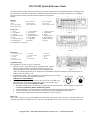
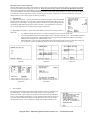
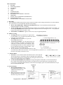
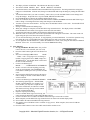
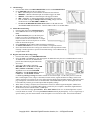
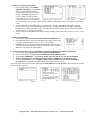
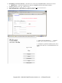
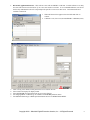
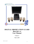
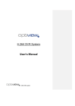
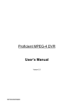
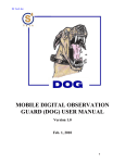
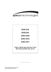
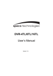
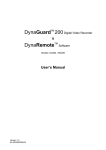
DX-TL910U
Digital Video Recorder
Simple Set-Up Guide
Copyright 2004 – Mitsubishi Digital Electronics America, Inc. – All Rights Reserved
1
DX-TL910U Quick Reference Guide
This Quick Reference Guide is designed to help you get quickly acquainted with your Mitsubishi DX-TL910U Digital Video
Recorder (DVR). This guide will also help you HOW TO program and perform commonly used functions. For additional
information please reference the DX-TL910U Installation and Operations
Manual.
Features:
Easy to Use
60PPS
Copy to CFC or VHS
PC25 or Web Browser
Duplex Operation
5 Quality Grades
Password Protection
Per Camera Settings.
Covert Camera
Network Support via DX-
Front View:
1. Power
2. Access Indicator
4. Timer Button
5. REC/STOP
7. Jog Dial
8. Split/Sequence
10. Pre-Alarm Indicator
11. M-Detect Indicator
13. Lock
14. Lock Button
16. Compact Flash Slot
17. Copy Button
19. Warning Reset
20. SETUP
22. Stop/Pause/Rev. Play & Play
3. Camera Sequence
6. Shuttle Ring
9. Zoom
12. Emergency Ind.
15. Video/Audio out
18. Alarm Interrupt
21. Search
Figure 1
Figure 2
Rear View:
1. Main Power Switch
4. Camera Out
7. Ground
10. Alarm In
13. Network Connector
2. Video Out
5. A/C Power Socket
8. MIC In
11. I/O Terminals
3. Camera In
6. Audio In/Out
9. Reset
12. RS-232C
Jog/Shuttle Usage:
The Jog/Shuttle is used for two types of operations
1. Playback Features – When Playing back, turning the Shuttle (outside
ring) Clock Wise (Forward) or Counter Clock Wise (Reverse) will
change the playback speed. When in Pause mode, the Shuttle is also
Figure 3
used to set the desired playback speed. From Pause turn the Shuttle to the desired Playback speed and press Pause to
hold the speed. Press Play to exit.
2. Programming of DVR – The Jog and Shuttle are used to navigate, select, change
and exit the various On Screen menu and sub-menu’s.
IMPORTANT INFORMTION:
• The Jog (inside ring) when turned CW or CCW is used to move the OSD cursor
Up/Down/Across selecting various functions. The Jog is also used to make a
change within the selected field (blinking in RED).
• The Shuttle (outside ring) is used to select, accept and exit the various functions. When a change is accepted, the
field turns from blinking RED to WHITE background.
a. Turning the Shuttle CW, selects the function (field goes from White background to blinking in RED).
b. To accept the change, turn the Shuttle CW, and the field goes from blinking RED back to White.
c. Turn the Shuttle CCW to EXIT and go back through the various menu layers.
Power Up:
This is a two step process, first, press the Main Power Switch ON (rear panel just above the Power cord), and from the front
of the unit press the Power Button (front #1). The unit will go through a series of power-up self test for about 20 seconds.
Copyright 2004 – Mitsubishi Digital Electronics America, Inc. – All Rights Reserved
2
First Time Power-UP (AUTO SETUP):
When the DVR is taken out of the box and turned on for the first time an AUTO SETUP program will guide you trough setting the DVR’s
Time and Date Settings and Performing AUTO SETUP. Ensure all cameras being used are connected to the DVR and are turned ON.
After entering Time and Date, PERFORM AUTO SETUP YES or NO menu will be displayed. If you choose YES, the DVR will guide
you through CAMERA Check and AUTO RECORDING SETTINGS. These values can be changed or fine tuned via the MENU settings.
If you select NO, the DVR will perform a power-up check and go to live mode. Listed below is the process and monitor screen shots
displayed when you select YES in the AUTO SETUP procedures.
1. AUTO SETUP:
A. TIME DATE ADJUST – Using the JOG/SHUTTLE as described on page 1, Select DAYLIGHT
SAVING with the SHUTTLE (turn to the right). When Selected, OFF will blink in RED, using the
JOG change to ON (if needed). To accept the change turn the SHUTTLE again to the right (ON will
stop blinking in RED and background for ON will be in white). Turn the SHUTTLE to the left to
exit. Using the same process set the Date and Time and go to EXECUTE.
B. PERFORM AUTO SETUP – Select YES with the SHUTTLE and with the JOG move down to
EXECUTE.
1.
In CAMERA CHECK when all the active cameras are displayed on the screen select EXECUTE.
2. In AUTO RECORD SETTING select the RECORD CYCLE XXX Hours and EXECUTE. The RECORD SETTINGS
screen will appear (Figure B-2a). The RECORD settings for Regular (PPS and GRADE) and Alarm (A-PPS and AGRADE) can be changed. Press POWER button to exit.
3. INITIALIZATION – Move the JOG to INITIALIZATION (Figure B-2b) and the unit will record the new settings and
go to Live Mode. At this point additional features can be set via the SETUP Menu (see next page).
2.
Figure B
Figure B-1
Figure B-2a
Figure B-2b
Figure B-2
SETUP MENU
Pressing the SETUP button found inside the DVR’s front door will access and display the
SETTINGS Menu. This Menu and its Sub Menus will allow you to program other
features of the DVR. Again, simply press the SETUP button and use the JOG/SHUTTLE
to move, select and make needed changes. To Exit the SETUP Menu, after the change has
been made (field not blinking in RED) and use the SHUTTLE CCW to exit the various
Sub-Menus until the live screen is displayed or simply press the SETUP button to exit.
Copyright 2004 – Mitsubishi Digital Electronics America, Inc. – All Rights Reserved
3
How to SECTION:
A. RECORD
B. MONITOR VIEWING
C. PLAYBACK
D. SEARCH
E. COPY
F. ALARM SETTING
G. MOTION SETTING
H. RECORDING & ALARM REC. SETTINGS
I.
TIMER REC
J.
INITIAL SETUP INFORMTION (HDD REPEAT)
K. NETWORK SETTINGS
L. ESTABLESHING A NETWORK CONNECTION
A. Recording:
1. Once the DVR is installed with all of the cameras connected, and the various settings in the DVR are set (Time and Date,
how each camera is to record and other important menu settings),
a. How to Activate RECORD – Simply press the REC/STOP (figure 1 item #5) button and when the button
illuminated in RED, the DVR is recording.
• To test recording simply turn the SHUTTLE CW, the monitor screen will black out and go back to live display. At
this time press the REV PLAY button and the DVR will playback the latest recording in reverse. To stop playback
just press the STOP button (see figure 2, #20).
• If any kind of a “WARNING ” appears on the screen, call your support department.
.
B. Monitor Viewing:
1. To change the view on your monitor to a single camera,
pres the number (1,2,3,or 4) that corresponds to the camera
you want to view in full screen.
2. To change back to the 4-camera view, press the
SPLIT/SEQUENCE button.
3. To Zoom in on an image – go to the single camera view
and press ZOOM an “X” appears on the monitor display
screen, this “X” shows the area to be zoomed-in. Press
the ZOOM again and the area will be expanded to 200%.
Press ZOOM again and image is enlarged 400%. Press
ZOOM again to exit the ZOOM function.
• The “X” will allow you to narrow the field and move to the
area under study when in the zoom mode. Use the navigational keys (under the 1,2, 3, 4 camera buttons) to move
the arrow to the field you wanted to review.
C. Playback Basics:
1. Press PLAY. The recorded content on the hard disc drive will be replayed.
The first time PLAY is activated the oldest recorded data will be displayed
first, after this when PLAY is pressed again, play will begin from last viewed
image (in its display format, one or 4 display).
2. Use the STOP/PAUSE/REV/PLAY buttons to navigate through the recorded data. To fast forward (when in
PLAY mode) turn the SHUTTLE ring clockwise, the further clock wise the SHUTTLE is turned the faster the
review speed. Pressing PAUSE while in FF will lock the current display speed. Press STOP and then PLAY to get
back to normal playback speed.
D. Search Function:
1. Date and Time Playback. Press
the SEARCH button (figure 2, #23)
TIME/DATE SEARCH is the
default setting.
• Make sure the cursor is next to the
SEARCH DATE line and turn the
SHUTTLE ring clockwise twice.
Copyright 2004 – Mitsubishi Digital Electronics America, Inc. – All Rights Reserved
4
•
•
2.
The display will turn red and flash. This indicates the data may be edited.
The format is YEAR MONTH DAY HOUR MINUTES SECONDS.
Turn the JOG dial to select MONTH and turn the SHUTTLE ring clockwise. The background of the setting item
changes to red and flashes. With the JOG, change to needed month and accept the change by turning the SHUTTLE
CW.
3. Turn the JOG dial to DAY you want to search by. Same as above, use the JOG/SHUTTLE to make changes and
accept the changes. Repeat the above steps for HOUR, MINUTE and SECOND.
4. Press SEARCH button to display the SEARCH SELECTION screen.
5. Check to see that the cursor is positioned at the SELECTION CAMERA NUMBER and turn the SHUTTLE ring to
make a change. The background of the setting item changes to red and flashes.
6. Turn JOG to select the camera number. You may choose an individual camera or select ALL. Turn the SHUTTLE
RING clockwise.
7. Setting is confirmed when all flashing stops.
8. When your settings are complete, turn the SHUTTLE ring counterclockwise. The display returns to the TIME
DATE SEARCH screen and the cursor appears on the left of the search date.
9. Turn the JOG dial and select EXECUTE and turn the SHUTTLE ring clockwise.
10. When the search is executed, the video of the requested date/time will appear in still frame. The search result will
appear using the split screen when all cameras are selected.
11. To view the selected image, press PLAY. To stop playback, press the STOP button. To cancel the operation at any
time during the set up, turn the SHUTTLE ring counterclockwise until you are back at the menu screen.
12. To view playback from the flash device, when in the SEARCH 2nd screen, select (using the JOG dial) PLAYBACK
DEVICE. Select CFC. You will normally view from the HDD/MAIN setting
E. Copy Function:
1. To copy the HDD or the CFC (make sure you first
remove the CFC cover and insert your CFC card).
2. Press the COPY button (right next to the Flash Card
port)
• The screen will display DIRECTION
MAIN
… HDD -->CFC. If copying to CFC, no change is
needed, if copying from CFC to HDD, change CFC
Æ HDD and exit. Use the SHUTTLE to Select and
the JOG to make the change.
3. Use the JOG dial and go to
MODE………….OVERWRITE/NO OVERWRITE
• NOTE: Overwrite will erase anything previously
saved on your flashcard. NO OVERWRITE will
record in the available space after your last recorded
event.
4. Select using the SHUTTLE ring and use the JOG to
make a change as needed. Use the Shuttle CCW to
exit this selection.
5. Use the JOG dial and go to TRANSFER PERIOD COPY MENU
• The following options appear: START*END,
START, LATEST DATA, (for example if you
select START, you only have to input the start
time of the needed video, no end time is needed.
This function will copy from given time and fill
the CFC with maximum data).
6. Input the required period setting.
7. Use the JOG/SHUTTLE ring to move/accept your
entries and use the SHUTTLE CCW to EXIT the Date settings
8. Use the JOG dial to move to EXECUTE and the SHUTTLE ring to activate the execution.
9. When complete, turn the SHUTTLE ring counterclockwise to return to the normal display mode.
10. Select EXECUTE and turn the SHUTTLE ring clockwise.
11. The monitor screen will indicate with a % number of copy process. When complete, the screen will indicate
“COMPLETE”.
12. Press the COPY button to remove the COPY menu from the monitor screen.
Copyright 2004 – Mitsubishi Digital Electronics America, Inc. – All Rights Reserved
5
F. Alarm Settings:
1. From the Main Menu select RECORD SETTING and select ALARM SETTING
2. Go to TRIGGER and select the type being used.
a. EXT = External/input at rear terminal is needed to activate an alarm
b. MD&EXT = Motion & External input are needed to triggers an Alarm
c. MD/EXT = Either Motion or External input will triggers an Alarm
d. MD = Alarm REC. is initiated when Motion is detected by active input.
e. Each ALARM can support multiple camera recording, simply select the
needed cameras in the RECORD CAMERA line.
f. Go back to the RECORD SETTING Menu (Shuttle CCW) and select the
ALARM RECORD DURATION time. Turn the Shuttle CCW to exit to Main Menu.
G. Motion Detection Setting:
1. From the Main menu select Motion Detection
2. Select camera/s that will be using MOTION (1
to16).
3. Set Detection Mask pixels (use the front panel
buttons #1-4 to move around the mask & use
button 8 to activate and 9 to deactivate. Use Split
Sequence button to activate all pixels or use Zoom
button to de-activate all pixels.
4. Select Sensitivity Level with the Shuttle and change with the Jog.
5. Set Motion Threshold from 1 to 192, lowest number (1) being most sensitive.
6. Select Test Mode and test above settings (test masked area with expected movement).
If change is needed, go back to specific area and make change. Exit to Main menu by
using the Shuttle CCW.
H. Regular and Alarm Recording Setting:
1. From the Main Menu, select RECORD SETTING.
2. Select ALARM or ALARM PLUS, this unit supports ALARM where only the active ALARM channel records or
ALARM PLUS where the ALARM channel
plus all other channels (Regular and Alarm)
also record.
3. Two types of Recording is supported.
RECORD (PPPS & GRADE) and ALARM
REC (A-PPS & A-GRADE). Using the
Jog/Shuttle move and select RECORD
SETTING. Use the Shuttle and Jog to move
to PPS field. Use the Shuttle to select
(red/blinking) and Jog to change the number of PPS for each camera input. Use the same process to select the
REC. Grade (Higher is best, Longer is minimum) for both sections (regular and alarm recording), and for each
camera connected. For cameras 10 to 16 Jog down and select NEXT PAGE and make changes. When this second
page is displayed, at the bottom of the screen ESTD REC. XXD/XXH/XXM represents how long the unit will
record 24H a day with the given camera inputs PPS and Quality settings.
• When Timer recording is used, the above information is entered in Timer Program Setting REC. MODE A-D.
• When done with step #3, test the RECORD settings to ensure they are acceptable. Remember, Higher PPS and
Grade means less time available to REC. on HD space.
• To test, exit all menu settings (press SETUP). Press REC. button (front view #6) button light turns red, and
record for about 30 seconds. To review press PLAY button and check playback quality. To see a single image or
specific camera, press the camera number on the front panel to view full screen video. Press STOP when done..
Copyright 2004 – Mitsubishi Digital Electronics America, Inc. – All Rights Reserved
6
I. Timer Record Setting (if being used):
1. From the Main Menu, select TIMER
PROGRAM SETTING. Select Pattern
P1 (P1-3 support different schedules,
selected Pattern will be used by DVR as
default). Select SET and enter time to
record. For DW enter day of week to
record where DAY is for every day, SPL
is days of week set by user at bottom of
the screen and HOL is for Holiday which is entered in Holiday Setting Menu of the Timer Program Setting menu
screen.
2. Use the Jog/Shuttle to enter Time (military) to start and stop recording. Select Mode A-D to REC. Camera
patterns A-D are setup in Timer Program Setting Main menu. Each Record Mode has ALARM and RECORD
SETTING (like in step E) plus other settings. For additional information on other supported functions like SKIP,
OVER and more, see the DVR User Manual.
3. The last setting is for MD (Motion Detection), if motion recording is being used in this set time set to ON, if not, set
to OFF.
J. Initial Setup/Information:
1. From the Main Menu Jog and Select INITIAL SETUP/INFORMATION
2. Select HDD SETTINGS, and set the HDD Repeat REC Main to ON if repeat
recording is needed (Repeat Record will write over existing data).
3. HDD REP REC SUB is used for ALARM RECORD only and set as above, if
set to OFF, when the SUB partition is full no more Alarms will be recorded.
When set to ON, Alarms are replaced FIFO.
K. Network Connection (if used, get IP, SUBNET & GATEWAY ADDRESS from network department):
1. From the Main Menu Jog and Select INITIAL SETUP/INFORMATION
2. From the SUB MENU (1) Jog and Select COMMUNICATION PORT SETTING
3. Jog and Select ETHERNET. Again with the Shuttle Select and with the Jog enter the IP ADDRESS.
4. With the Jog/Shuttle enter SUB NET MASK & GATEWAY ADDRESS, use the Shuttle to accept.
5. Use the Jog and Shuttle to go to ALARM NOTIFICATION SETTING and enter the IP ADDRESS to
be notified when a WARNING, ALARM SENSE, REC MODE (when set to ON).
Once all information is entered (fields not blinking) press SETUP Button to accept all entries. The unit will reset updating
information and turn back on.
Copyright 2004 – Mitsubishi Digital Electronics America, Inc. – All Rights Reserved
7
L. Establishing a Network Connection – The DVR can be connected by WEB BROWSER or DX-PC25U software.
• WEB Browser – Launch your Web Browser and at the ADDRESS LINE input the DVRs IP address.
1. USER ID (default) is “root” (no “” and lower case)
2. PASSWORD (default) is “admin000” (no “” and lower case) also 000 are zeros not letter o.
3. Click on LOGIN button. Up to 10 users can log in at one time.
3. Select LIVE, PLAYBACK or ….. LOGOUT
to EXIT. (up to 10 users can connect at once).
4. In Playback to perform Time Date Search, select
single screen mode first. The SEARCH buttons will
appear.
Copyright 2004 – Mitsubishi Digital Electronics America, Inc. – All Rights Reserved
8
•
DX-PC25U Application Software – This software comes with each DVR in a CD form. Load the software to as many
PC’s that will need access to the DVR. Up to 5 users can connect at one time. It is recommended that one user also be
the Security Administrator who will setup and provide specific level access to other users. Launch the Software to
establish a connection.
1.
2.
3.
4.
5.
6.
7.
When the Network box appears select the DVR and click on
connect.
USER ID = root (lower case) & PASSWORD = admin000 (zeros)
LIVE viewing is the default, for Playback click on Live button one time
Select Camera or Display for display format
Select NETWORK from pull down menu to access more features
For changing MENU via Remote go to CONFIG of NETWORK pull down menu
For additional functions go to HELP pull down button and review OPERATIONS MENU.
Copyright 2004 – Mitsubishi Digital Electronics America, Inc. – All Rights Reserved
9