1
OWNER'S MANUAL
MINI COOPER
MINI COOPER S
Contents
From A to Z
Online Edition for Part No. 01 41 0 156 724 - © 01/02 BMW AG
Online Edition for Part No. 01 41 0 156 724 - © 01/02 BMW AG
CONGRATULATIONS ON YOUR NEW MINI
This Owner's Manual should be considered a permanent part of this vehicle. It should stay with the
vehicle when sold to provide the next owner with important operating, safety and maintenance
information.
This manual is supplemented by a Service and Warranty Information Booklet for US models or a
Warranty and Service Guide Booklet for Canadian models.
We recommend that you read this publication thoroughly.
Your MINI is covered by the following warranties:
– New Vehicle Limited Warranty
– Limited Rust Perforation Warranty
– Federal Emissions System Defect Warranty
– Federal Emissions Performance Warranty
– California Emission Control System Limited Warranty
Detailed information about these warranties is listed in the Service and Warranty Information
Booklet for US models or in the Warranty and Service Guide Booklet for Canadian models.
We wish you an enjoyable driving experience.
Online Edition for Part No. 01 41 0 156 724 - © 01/02 BMW AG
Using this Owner's Manual
At a glance
Controls and features
Notes on the Owner's Manual 6
Symbols used 6
Symbol for vehicle parts 6
Your individual vehicle 6
Editorial notice 7
For your own safety 8
Reporting safety defects 9
Cockpit 12
Display elements 13
Display elements with navigation
system 14
Indicator and warning lamps 15
Multifunction steering wheel MFL 18
Opening and closing:
Keys 22
Central locking system 23
Opening and closing – from outside 23
Opening and closing – from inside 26
Tailgate 27
Electric power windows 28
Sliding/tilt sunroof 29
Roller sun blind 30
Adjustments:
Correct sitting posture 31
Seats 31
Entry to the rear 33
Seat heating 34
Head restraints 34
Safety belts 35
Steering wheel 35
Mirrors 36
Airbags 37
Transporting children safely 38
Vehicle Memory 41
© 2002 Bayerische Motoren Werke
Aktiengesellschaft
Munich, Germany
Reprinting, including excerpts, only with the
written consent of BMW AG, Munich.
Order No. 01 41 0 156 724
US English II/02
Printed in Germany
Printed on environmentally friendly paper
(bleached without chlorine, suitable for recycling).
2
Online Edition for Part No. 01 41 0 156 724 - © 01/02 BMW AG
CONTENTS
Loading and transporting cargo:
Luggage compartment cover 71
Foldable rear backrest 71
Loading cargo 72
Roof-mounted luggage rack 73
DATA
REPAIRS
Wheels and tires:
Tire inflation pressure 80
Tire condition 82
Tire replacement 83
Wheel and tire combinations 84
Winter tires 85
Snow chains 85
INDEX
Interior conveniences:
Glove compartment 70
Ashtray/Beverage holder 70
Cigarette lighter 70
Special operating instructions:
Break-in procedures 76
General driving notes 76
Refueling 77
Fuel specifications 78
Antilock Brake System (ABS) 78
Brake system 79
OVERVIEW
Everything under control:
Odometer 55
Tachometer 55
Fuel gauge 55
Coolant temperature gauge 56
Service Interval Display 57
Clock 57
Computer 58
Controlling the climate for pleasant
driving:
Air conditioner system 64
Automatic climate control 67
Care and maintenance
CONTROLS
Technology for safety and driving
convenience:
Automatic Stability Control plus Traction
(ASC+T) 60
Dynamic Stability Control (DSC) 61
Flat Tire Monitor 62
Park Distance Control (PDC) 63
OPERATION
Driving:
Ignition lock 42
Starting the engine 42
Switching off the engine 43
Parking brake 44
Manual transmission 45
Continuously Variable automatic
Transmission (CVT) 46
Parking lamps/Low beams 49
Indicator/Headlamp flasher 49
Instrument lighting 50
Fog lamps 50
Interior lamps 50
Light-emitting diodes 51
Washer/Wiper system 51
Cruise control 53
Online Edition for Part No. 01 41 0 156 724 - © 01/02 BMW AG
3
CONTENTS
In the engine compartment:
Hood 86
Engine compartment –
MINI COOPER 87
Engine compartment –
MINI COOPER S 88
Washer fluid 89
Engine oil 89
Coolant 91
Brake fluid 92
Maintenance and care:
MINI Maintenance System 93
Caring for your vehicle 94
Vehicle immobilization 96
Laws and regulations:
OBD interface socket 96
Technical modifications 96
California Proposition 65 Warning 97
4
Owner Service Procedures
Technical data
Replacement procedures:
Onboard tool kit 100
Windshield wiper blades 100
Lamps and bulbs 101
Repairing a flat tire 106
Changing tires – MINI
with space-saver spare tire 106
Flat tire – safety tires 110
Battery 111
Fuses 112
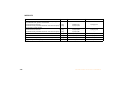
Engine data 120
Dimensions 121
Weights 122
Capacities 123
Electrical system 124
Giving and receiving assistance:
Warning triangle 113
First-aid kit 113
Jump-starting 113
Tow-starting and towing 115
Online Edition for Part No. 01 41 0 156 724 - © 01/02 BMW AG
OVERVIEW
Index
INDEX
DATA
REPAIRS
OPERATION
CONTROLS
Everything from A to Z 128
Online Edition for Part No. 01 41 0 156 724 - © 01/02 BMW AG
5
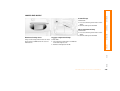
Notes on the Owner's Manual
Symbols used
Your individual vehicle
In compiling this Owner's Manual we have
made every effort to furnish you with a
convenient reference source affording
quick access to all the essentials. The
fastest way to find detailed information on
any specific subject is to turn to the
comprehensive index at the back of the
manual. If you wish to gain an initial overview of your vehicle, you will find this in the
first chapter.
Indicates precautions that must
be followed precisely in order to
avoid the possibility of personal injury
and serious damage to the vehicle.
The manufacturer of your MINI is the
Bayerische Motoren Werke Aktiengesellschaft (BMW AG).
Should you wish to sell your MINI at some
time in the future, please remember to
hand over this Owner's Manual to the new
owner; it is an important part of the
vehicle.
Refers to measures that can be taken We hope you will understand that equipto help protect the environment.
ment and features are included that you
might not have chosen for your vehicle. To
< Marks the end of a specific item of
assist you in identifying possible variations
information.
between your own vehicle and the
manual's contents, the passages describing
* Indicates special equipment, countryoptional accessories and special equipment
specific equipment and optional extras.
are marked with an asterisk *.
If you have any additional questions, your
MINI center will be glad to advise you.
Contains information that will
assist you in gaining the optimum
benefit from your vehicle and enable you
to care more effectively for your vehicle.
Identifies systems or components,
which your MINI center can either
activate or adapt to suit an individual
driver's requirements ("Vehicle Memory"),
see page 41.
On purchasing your MINI, you have decided
in favor of a model with individualized
equipment and features. This Owner's
Manual describes the entire array of
options and equipment available with a
specific manufacturer model range.
If your MINI features equipment that is not
described in this Owner's Manual (a car
radio, for instance), we have enclosed additional Owner's Manuals. We ask you to
read these manuals as well.
Symbol for vehicle parts
Indicates that you should consult
the relevant section of this Owner's
Manual for information on a particular part
or assembly.
6
Notes
Symbols
Online Edition for Part No. 01 41Your
0 156 724
- © 01/02 BMW
AG
individual
vehicle
OVERVIEW
Editorial notice
OPERATION
CONTROLS
The manufacturer pursues a policy of
continuous, ongoing development that is
conceived to ensure that the MINI
continues to embody the highest quality
and safety standards combined with
advanced, state-of-the-art technology. For
this reason, it is possible that the features
described in this Owner's Manual could
differ from those on your vehicle. Nor can
errors and omissions be entirely ruled out.
INDEX
DATA
REPAIRS
You are therefore asked to appreciate that
no legal claims can be entertained on the
basis of the data, illustrations or descriptions in this Owner's Manual.
Online Edition for Part No. 01 41 0 156 724 - © 01/02 BMW AG
7
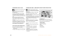
For your own safety
Use unleaded gasoline only. Fuels
containing up to and including
10% ethanol or other oxygenates with up
to 2.8% oxygen by weight (i.e. 15% MTBE or
3% methanol plus an equivalent amount
of co-solvent) will not void the applicable
warranties with respect to defects in materials or workmanship. Field experience has
indicated significant differences in fuel
quality (volatility, composition, additives,
others) among gasolines offered for sale in
the United States and Canada. The use of
poor-quality fuels may result in driveability,
starting and stalling problems especially
under certain environmental conditions,
such as high ambient temperature and
high altitude.
Should you encounter driveability problems which you suspect could be related to
the fuel you are using, we recommend that
you respond by switching to a recognized
high-quality brand.
Failure to comply with these recommendations may result in unscheduled maintenance.
Obey pertinent safety rules when you are
handling gasoline.<
8
Important safety information.
sional advice on using these items, are
available from all MINI centers.
For your own safety, use genuine parts and Installation and operation of non-MINI
accessories approved by the manufacturer approved accessories such as alarms,
of the MINI.
radios, amplifiers, radar detectors, wheels,
When you purchase accessories tested
suspension components, brake dust
and approved by the manufacturer of the
shields, telephones (including operation
MINI and Original MINI Parts, you simulta- of any portable cellular phone from within
neously acquire the assurance that they
the vehicle without using an externally
have been thoroughly tested by the manu- mounted antenna) or transceiver equipfacturer of the MINI to ensure optimum
ment (e.g. CB, walkie-talkie, ham radio or
performance when installed on your
similar) may cause extensive damage to
vehicle.
the vehicle, compromise its safety, interfere with the vehicle’s electrical system
The manufacturer of the MINI warrants
these parts to be free from defects in mate- or affect the validity of the MINI Limited
Warranty. See your MINI center for addirial and workmanship.
tional information.<
The manufacturer of the MINI will not
accept any liability for damages resulting
Maintenance, replacement, or repair
from installation of parts and accessories
of the emission control devices and
not approved by the manufacturer of the
systems may be performed by any automoMINI.
tive repair establishment or individual
The manufacturer of the MINI cannot test using any certified automotive part.<
every product from other manufacturers to
verify if it can be used on a MINI safely and
without risk to either the vehicle, its operation, or its occupants.
Original MINI Parts, MINI Accessories and
other products approved by the manufacturer of the MINI, together with profes-
Online Edition for Part No. 01 41 0 156 724 - © 01/02 BMW AG
OVERVIEW
CONTROLS
The following only applies to vehicles owned and operated in the US.
INDEX
DATA
To contact NHTSA, you may either call the Auto Safety Hotline toll-free at 1-800-424-9393 (or 366-0123 in Washington, D.C.
area) or write to: NHTSA, U.S. Department of Transportation, Washington, D.C. 20590. You can also obtain other information
about motor vehicle safety from the Hotline.
REPAIRS
If NHTSA receives similar complaints, it may open an investigation, and if it finds that a safety defect exists in a group of
vehicles, it may order a recall and remedy campaign. However, NHTSA cannot become involved in individual problems
between you, your dealer or BMW of North America, LLC.
OPERATION
REPORTING SAFETY DEFECTS
If you believe that your vehicle has a defect which could cause a crash or could cause injury or death, you should immediately
inform the National Highway Traffic Safety Administration (NHTSA) in addition to notifying BMW of North America, LLC.,
P.O. Box 1227, Westwood, New Jersey 07675-1227, Telephone (201) 307-4000.
Online Edition for Part No. 01 41 0 156 724 - © 01/02 BMW AG
9
10
Online Edition for Part No. 01 41 0 156 724 - © 01/02 BMW AG
OWNER SERVICE PROCEDURES
TECHNICAL DATA
INDEX
Overview
Online Edition for Part No. 01 41 0 156 724 - © 01/02 BMW AG
OVERVIEW
CONTROLS
OPERATION
REPAIRS
OPERATION, CARE, MAINTENANCE
DATA
CONTROLS
INDEX
OVERVIEW
11
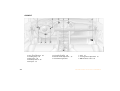
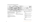
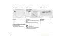
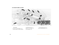
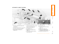
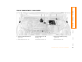
COCKPIT
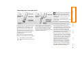
1 > Parking lamps/Low beams 49
> Turn signal indicators 49
> Standing lamps 49
> High beams 49
> Headlamp flasher 49
> Computer 58
12
2
3
4
5
Washer/Wiper system 51
Instrument lighting 50
Outside mirror adjustment 36
Hazard warning flashers
6
7
8
9
Hood release 86
Horn 18
Steering wheel adjustment 35
OBD interface socket 96
Online Edition for Part No. 01 41 0 156 724 - © 01/02 BMW AG
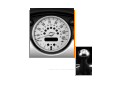
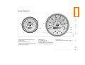
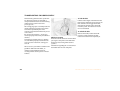
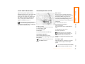
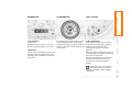
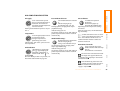
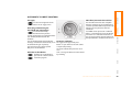
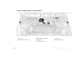
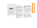
4 Indicator for
> Odometer 55
> Trip odometer 55
> Service Interval 57
2 Display for computer 58
> Program display for Continuously
3 Speedometer with indicator and warning
Variable Transmission (CVT) 48
lamps, see from page 15
5 Trip odometer, reset to zero 55
6 Fuel gauge 55
7 Engine coolant temperature gauge 56
INDEX
1 Tachometer 55
with indicator and warning lamps, see
from page 15
DATA
REPAIRS
OPERATION
CONTROLS
OVERVIEW
DISPLAY ELEMENTS
Online Edition for Part No. 01 41 0 156 724 - © 01/02 BMW AG
13
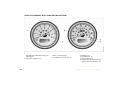
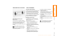
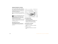
DISPLAY ELEMENTS WITH NAVIGATION SYSTEM *
1 Tachometer 55
with indicator and warning lamps, see
from page 15
2 Display for computer 58
14
3 Speedometer with indicator and warning 5 Indicator for
lamps, see from page 15
> Odometer 55
> Trip odometer 55
4 Trip odometer, reset to zero 55
> Service Interval 57
> Program display for Continuously
Variable Transmission (CVT) 48
Online Edition for Part No. 01 41 0 156 724 - © 01/02 BMW AG
Do not continue driving, otherwise,
the engine could be damaged
because of inadequate lubrication.<
CONTROLS
OPERATION
If the drive belt is defective, do not
With navigation system option:
continue driving. The engine could be
Coolant temperature warning
damaged due to overheating. When the
lamp in the speedometer ●
power-assist is deactivated, increased
If the lamp comes on while opersteering effort is required.<
ating the vehicle, the engine has overheated. Switch off the engine immediately
Engine oil pressure ●
and allow to cool down, see also page 56.
Stop immediately. Switch off
engine. Check the engine oil and
top up as required. Please contact the
nearest MINI center.
REPAIRS
If a malfunction should occur in one of
these systems, the corresponding lamp
does not go out after the engine is started
or it lights up while the vehicle is moving.
You will see how to react correctly to this
below.
DATA
The system runs a check on the warning
and indicator lamps marked by "●" each
time you switch on the ignition. They each
light up once for different periods of time.
Brake warning lamp ●
If the lamp comes on when the
Battery charge current ●
parking brake is not engaged:
The battery is no longer being
Check
the
brake fluid level. Before driving
charged. Indicates a defective alterfurther,
be
sure to comply with the infornator drive belt or a problem with the
mation on pages 79, 57 and 92.
charge circuit. Please contact the nearest
Brake warning lamp for Canadian
MINI center.
models.
If this lamp lights up, the power-assist for
steering can be deactivated.
Red: stop immediately
INDEX
Technology
that monitors itself
OVERVIEW
INDICATOR AND WARNING LAMPS
Online Edition for Part No. 01 41 0 156 724 - © 01/02 BMW AG
15
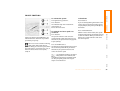
INDICATOR AND WARNING LAMPS
Yellow: stop immediately
Flat Tire Monitor ●
Flashes: tire failure.
Red and yellow: continue to drive;
drive cautiously
Red: an important reminder
Brake warning lamp
Brake warning lamp together with
with parking brake applied.
yellow
indicator
lamps
for
ABS,
EBV
More information on the parking
Reduce speed immediately and
and ASC+T/DSC:
brake on page 44
stop the vehicle.
The control system ABS, EBV and
Parking brake lamp for Canadian
With safety (run-flat) tires:
ASC+T/DSC has failed. Drive
models.
Reduce vehicle speed carefully to under
cautiously and defensively. Avoid
50 mph (80 km/h).
full brake applications. Please have
Fasten safety belts ●
In both cases, avoid hard brake applications
the system checked by your MINI
Depending on model, with acoustic
and steering maneuvers. Check the tire
center as soon as possible.
signal*. Lights up either for several
inflation pressures.
More information on pages 60, 61
seconds or until the belt is engaged, deConduct in the event of a flat tire, see
Brake warning lamp together with pending on version.
pages 106, 110.
the yellow indicator warning lamps More information on page 35
General information on the system, see
ABS, EBV and ASC+T/DSC for CanaDepending on the level of equipment,
page 62
dian models.
the indicator lamp is in the vicinity of
the navigation system.<
Airbags ●
Please have the system inspected
at your MINI center.
More information on pages 31, 37
Depending on the level of equipment,
the indicator lamp is in the vicinity of
the navigation system.<
Hood/tailgate
Lights up when the hood and/or
tailgate are open.
More information on pages 27, 86
16
Online Edition for Part No. 01 41 0 156 724 - © 01/02 BMW AG
"Service Engine Soon" warning
lamp for Canadian models.
Turn signal indicators
Flashes when turn signal indicator
is on, also for trailer towing.
Rapid flashing: the system is defective.
More information on page 49
Cruise control*
Lights up when the cruise control is
activated. Operation via the multifunction steering wheel.
More information on page 53
INDEX
Engine electronics* ●
Blue: for your information
Malfunction
in the engine elecABS indicator lamp for Canadian
High beams
tronics. You can continue to drive
models.
Comes on when the high beams
with reduced engine output or engine
are on or the headlamp flasher is
speed. Please have the system inspected at actuated.
Automatic Stability Control plus
your MINI center.
More information on page 49
Traction (ASC+T)/Dynamic Stability
Control (DSC) ●
Indicator lamp flashes:
System active: drive and braking forces are
regulated.
The indicator lamp stays lit:
ASC+T/DSC switched off with button or
defective. In the event of a defect: please
have the system inspected at your MINI
center.
More information on pages 60, 61
CONTROLS
Green: for your information
OPERATION
Antilock Brake System (ABS) ●
ABS has been deactivated in
response to system malfunction.
Conventional braking efficiency is available. Please have the system inspected
at your MINI center.
More information on page 78
Service Engine Soon ●
If the warning lamp comes on
either continuously or intermittently, this indicates a malfunction in the
emissions-related electronic systems.
Although the vehicle remains operational,
you should have the systems checked by
your MINI center at the earliest possible
opportunity.
REPAIRS
Flat Tire Monitor ●
Stays lit: the system is defective.
Please have the system inspected
at your MINI center.
More information on page 62
DATA
Yellow: check as soon as possible
OVERVIEW
INDICATOR AND WARNING LAMPS
Online Edition for Part No. 01 41 0 156 724 - © 01/02 BMW AG
17
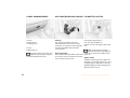
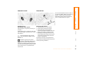
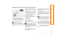
MULTIFUNCTION STEERING WHEEL MFL *
The control buttons integrated within the
MFL multifunction steering wheel have
been designed to allow you to operate a
number of accessories both quickly and
safely, without taking your eyes from the
road:
> Some audio source functions
> Cruise control.
The illustration shows the possible full
equipment level. For further details, please
consult the description of the relevant item
of equipment.
Buttons facing the driver
Buttons facing away from the driver
1 Cruise control: activate/interrupt/
deactivate
2 Continue cruise control
3 Horn
4 Cruise control: store and accelerate (+)
5 Cruise control: store and decelerate (–)
Left:
1 > Radio
Press briefly: scans for stations in FM
band
Extended pressure: station tuning
> CD
Press briefly: jump to next track
Extended pressure: fast forward in track
> Cassette
Press briefly: stop track scan or fast
forward
Extended pressure: fast forward/
rewind
Right:
1 Volume
2 Switch between radio, cassette and CD
18
Online Edition for Part No. 01 41 0 156 724 - © 01/02 BMW AG
OVERVIEW
CONTROLS
OPERATION
REPAIRS
DATA
INDEX
Online Edition for Part No. 01 41 0 156 724 - © 01/02 BMW AG
19
20
Online Edition for Part No. 01 41 0 156 724 - © 01/02 BMW AG
OWNER SERVICE PROCEDURES
TECHNICAL DATA
INDEX
Controls
Online Edition for Part No. 01 41 0 156 724 - © 01/02 BMW AG
OVERVIEW
CONTROLS
OPERATION
REPAIRS
OPERATION, CARE, MAINTENANCE
DATA
CONTROLS
INDEX
OVERVIEW
21
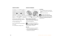
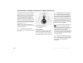
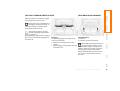
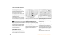
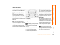
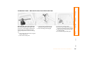
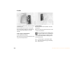
KEYS
Initializing the master key with remote
control
When you activate a master key with
remote control (replacement, additional
key or after a battery change), it must be
initialized.
This initialization can be performed in two
ways:
Press button 1 or button 2, see page 24,
four times in succession
Depending on the equipment fitted, your
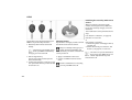
MINI has up to three key variations:
1 Master key with remote control and
battery
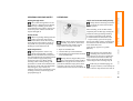
If the battery is discharged, please
consult your MINI center. Battery
changing, see next column.<
or
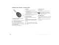
Changing battery
Replace if it is no longer possible to unlock
the vehicle via the remote control.
Only use a battery of the type specified on the battery (CR 2032) and
make absolutely sure that it is fitted in the
correct position.<
1. Apply a screwdriver at the recess
2 Door and ignition key
2. Use the screwdriver to lever out the
This key can only be used to open the
cover.
doors mechanically
3 Spare key for storage in a safe place, such
Return used batteries to a recycling
as in your wallet. This key is not intended
point or your MINI center.<
for constant use
22
if the vehicle is unlocked:
1. Switch the ignition on briefly (position 2)
and then off
2. Within 10 seconds, press button 1 and
button 2, see page 24, in succession.
In the event of a system malfunction,
please contact your MINI center. You
can also obtain replacement keys and
batteries there.<
Online Edition for Part No. 01 41 0 156 724 - © 01/02 BMW AG
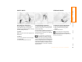
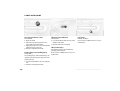
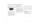
The concept
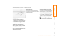
Via remote control
For US owners only
The central locking system is ready for
operation whenever the driver's door is
closed. The doors, the tailgate and the fuel
filler door are unlocked or locked.
The remote control gives you an exceptionally convenient method for unlocking and
locking your vehicle. It also offers another
function:
The transmitter and receiver units comply
with part 15 of the FCC (Federal Communication Commission) regulations. Operation
is governed by the following:
The central locking system can be operated:
To open the tailgate, refer to page 24.
FCC ID:
The tailgate will open slightly, regardless of
whether it was locked or unlocked.
Children might be able to lock the
doors from the inside. Always take
the vehicle keys with you so that the
vehicle can be opened again from the
outside at any time.<
> This device may not cause harmful interference, and
> this device must accept any interference
received, including interference that may
cause undesired operation.
Any unauthorized modifications or
changes to these devices could void
the user's authority to operate this equipment.<
INDEX
are also switched on.
This device complies with part 15 of the
FCC Rules. Operation is subject to the
following two conditions:
OPERATION
If operated from outside, the anti-theft
system is activated at the same time. This
prevents the doors from being unlocked via If the vehicle has been properly locked
using the remote control, the hazard
safety lock buttons or door handles.
warning system lights up once.
In the event of an accident, the central
locking system unlocks automatically. The When the vehicle is unlocked, the hazard
hazard warning system and interior lamps warning system does not react.
Compliance statement:
REPAIRS
Whenever you unlock (lock) the vehicle,
you simultaneously deactivate (activate)
the anti-theft system, and switch the interior lamps on (off).
DATA
> From outside via the remote control as
well as via the door lock
> From inside by pressing a button.
LX8765S
LX8765E
LX8CAS
OVERVIEW
OPENING AND CLOSING – FROM OUTSIDE
CONTROLS
CENTRAL LOCKING SYSTEM
Online Edition for Part No. 01 41 0 156 724 - © 01/02 BMW AG
23
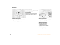
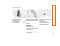
OPENING AND CLOSING – FROM OUTSIDE
To unlock
To lock and secure
Press button 2.
1. Press button 1 once to unlock the
The hazard warning system flashes once.
driver's door only
2. Press button 1 a second time to unlock
Do not lock the vehicle if there are
the other door as well as the tailgate and
passengers still inside, because they
the fuel filler door.
cannot
unlock the doors.<
When the vehicle is unlocked, the hazard
warning system does not react.
Non-MINI systems
To open the tailgate
1 Unlocking and opening the tailgate
2 Locking and securing
External systems or devices may cause local
interference in the functions of the remote
control.
Hold button 1 pressed for approx. five
seconds.
The tailgate will open slightly, regardless
of whether it was previously locked or
unlocked.
In this case, use the master key to unlock
the door lock.
If the remote control does not react,
the battery is discharged.
In the event of a system malfunction,
Before and after a trip, be sure that
please contact your MINI center. You can
the tailgate was not opened unintenalso obtain replacement keys and batteries tionally.<
from your MINI center.
Battery changing, see page 22.<
24
Online Edition for Part No. 01 41 0 156 724 - © 01/02 BMW AG
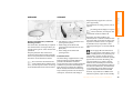
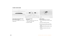
You can also operate the power windows
and the sliding/tilt sunroof via the door
lock.
Turn the key to the extreme left or right to
unlock/lock the door.
> To open: with the door closed, turn the
key to the "Unlock" position and hold it
> To close: with the door closed, turn the
key to the "Lock" position and hold it.
Via the door lock
Watch during the closing process to
be sure that no one is injured.
Releasing the key stops the operation.<
REPAIRS
1. One turn of the key in the driver's
door lock unlocks the driver’s door only
2. Turning the key a second time unlocks
the other door, the tailgate and the fuel
filler door.
CONTROLS
Convenience feature via door lock
(in the event of electrical malfunction)
OPERATION
Manual operation
OVERVIEW
OPENING AND CLOSING – FROM OUTSIDE
If the vehicle has been properly locked, the
hazard warning system flashes once.
When the vehicle is unlocked, the hazard
warning system does not react.
INDEX
DATA
Do not lock the vehicle if there are
passengers still inside, because they
cannot unlock the doors.<
Online Edition for Part No. 01 41 0 156 724 - © 01/02 BMW AG
25
OPENING AND CLOSING – FROM INSIDE
The central locking system can be
locked automatically as soon as you
begin to drive if you desire. This can be
adjusted to be vehicle-specific.<
To lock
To unlock and open the doors
press the individual safety lock buttons
down.
1. Touch the switch for the central locking
system
2. Pull the door handle above the armrest
With this switch, you operate the central
locking system when the doors are closed.
The doors and tailgate are unlocked or
locked only.
Touch the switch for the central locking
system
or
Children might be able to lock the
doors from the inside. Always take
or
the vehicle's keys with you so that you can
pull the door handle for each door twice: to open the vehicle again from the outside at
any time.<
unlock first and then open.
Convenience opening mode
From ignition key position 1:
The anti-theft system is not activated. Also, Hold the switch in the "Unlock" position.
the fuel filler door remains unlocked to
The windows and sliding/tilt sunroof open.
allow refueling.
If the remote control has been used
to unlock only the driver's door, see
page 24, and you touch the switch when
the driver's door is open, the other door,
the tailgate, and the fuel filler door are
unlocked.
If the driver's door is closed, touching the
switch locks it.<
26
Convenience closing is not possible
by means of the central locking
system. You should therefore close all the
windows and the sliding/tilt sunroof individually.<
Online Edition for Part No. 01 41 0 156 724 - © 01/02 BMW AG
In the event of an electrical malfunction,
The handle recesses in the interior trim
you can also operate the tailgate manually. panel of the tailgate make it easier to pull
the lid down.
3. Fold the rear seat bench upwards
Opening with the remote control, see
page 24.
4. Pull the ring.
The tailgate is unlocked.
To avoid injuries, be sure that the
travel path of the tailgate is clear
when it is closed, as with all closing procedures.
Operate the vehicle only when the tailgate
is closed. Otherwise, exhaust fumes could
penetrate the interior of the vehicle.
Should it be absolutely necessary to
operate the vehicle with the tailgate open:
1. Close all windows. Shut the sliding/tilt
sunroof
2. Sharply increase the air supply for the air
conditioning or automatic climate
control, see pages 64 and/or 67.<
Online Edition for Part No. 01 41 0 156 724 - © 01/02 BMW AG
REPAIRS
Press the button in the handle.
The tailgate opens slightly.
Closing
DATA
Manual operation
INDEX
Opening from outside
OPERATION
CONTROLS
OVERVIEW
TAILGATE
27
ELECTRIC POWER WINDOWS
To close:
After the ignition has been switched off:
Press the switch upwards.
The window closes until you release the
switch
You can use the electric power windows as
long as no one opens any of the doors.
If a door is opened during operation, the
opening/closing process stops immediately.
or
when the engine is running:
Briefly press the switch upwards.
The window closes automatically.
Pressing the switch again stops the operation.
Open and close windows
From ignition key position 1:
To open:
Press the switch downwards.
The window opens until you release the
switch
The window on the front passenger
side cannot be closed automatically.<
When leaving the vehicle, always
remove the ignition key from the
lock and remember to close the doors to
prevent children from operating the power
windows and injuring themselves, etc.<
For the convenience mode via the door
lock, refer to page 25.
Watch during the closing process to
be sure that no one is injured.<
or
briefly press the switch downwards.
The window opens automatically.
Pressing the switch again stops the operation.
28
Online Edition for Part No. 01 41 0 156 724 - © 01/02 BMW AG
After the ignition has been switched off:
You can still operate the sliding/tilt sunroof
for up to one minute, as long as no one
opens any of the doors.
If a door is opened during operation, the
opening/closing stops immediately.
Automatic opening and closing
Raising – Opening – Closing
To open:
From ignition key position 1:
Press the switch
To close:
or
1. Push the switch past the resistance
point:
The sunroof closes to the raised position
2. Push the switch again:
The sunroof closes completely.
push the switch backwards to the resistance point.
Opening and closing
1. Push the switch in the desired direction
until you feel resistance and hold in this
position
2. Release the switch when the desired
position has been reached.
Touching the switch briefly during opening
or closing stops the movement immediately.
DATA
To raise:
REPAIRS
Push the switch past the resistance point:
The sunroof opens completely
INDEX
For the convenience mode via the door
lock, refer to page 25.
CONTROLS
Do not use force to close the sliding/
tilt sunroof in its raised position, as
damage to the mechanism could result.<
OPERATION
To prevent injuries, exercise care
when closing the sliding/tilt sunroof
and keep it in your field of vision until it is
shut.
When leaving the vehicle, always remove
the ignition key from the lock and
remember to close the doors to prevent
children from operating the sunroof and
injuring themselves, etc.
Be sure that adequate clearance is maintained for the opening path of the sliding/
tilt sunroof, otherwise damage can occur.<
OVERVIEW
SLIDING/TILT SUNROOF *
Online Edition for Part No. 01 41 0 156 724 - © 01/02 BMW AG
29
SLIDING/TILT SUNROOF *
ROLLER SUN BLIND*
Safety feature
As of approximately the middle of the roof
opening, if the sliding/tilt sunroof encounters resistance during closing, the closing
operation is interrupted and the sunroof
opens again slightly.
Despite this safety feature, be
extremely careful that the closing
path of the sunroof is not obstructed whenever it is closed. Otherwise, triggering the
closing-force limitation may not be
ensured in some situations (with very thin
objects, for instance).
You can override this safety feature by
pressing the switch beyond the resistance
point and holding it.<
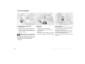
Manual opening and closing
1 Opening
In the event of an electrical malfunction,
you can also operate the sliding/tilt
sunroof manually:
1. Press the button in the handle, see
arrow 1.
The cap is unlocked
2. Guide the roller sun blind towards the
back.
1. Push the clock towards the interior and
remove
2 Use an Allen wrench to turn the sliding/
tilt sunroof in the desired direction.
2 Closing
1. Use the handle to pull the roller sun
blind forwards
2. Engage the handle in the device, see
arrow 2.
30
Online Edition for Part No. 01 41 0 156 724 - © 01/02 BMW AG
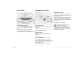
Sitting correctly with airbags
Adjusting the seats, see next page.
INDEX
Always maintain an adequate
distance between yourself and all of
the airbags. Always hold the steering wheel
by the rim with the hands at the 9 and
3 o'clock positions to keep any chance of
injury to hands or arms to an absolute
minimum, should the airbag be deployed.
No one and nothing is to come between the
airbags and the seat occupant.
Never use the front passenger airbag cover
as a storage surface for objects of any kind,
or as a support for legs or feet, as this will
increase the risk of injury in a collision severe For information on using the safety belts,
refer to page 35.
enough in which the airbag will deploy.<
OVERVIEW
Never try to adjust your seat while
operating the vehicle. The seat could
respond with an unexpected movement,
and the ensuing loss of vehicle control
could lead to an accident.
Never ride with the backrest reclined to an
extreme horizontal angle (especially important for front passengers to remember).
Keep the backrest relatively upright to
minimize the risk of sliding under the
safety belt and sustaining injury in an accident.<
CONTROLS
Important adjustment information
Never allow more than one person to
wear a single safety belt. Never allow
infants or small children to ride in a
passenger's lap. Avoid twisting the belt
while routing it firmly across the hips and
shoulder, wear it as snugly against your
body as possible. Do not allow the belt to
rest against hard or fragile objects. Do not
route the belt across your neck, or run it
across sharp edges. Be sure that the belt
does not become caught or jammed.
Avoid wearing bulky clothing that prevents
the belt from fitting properly, and pull on
the belt periodically to retension it over
your shoulders. In the event of a frontal
impact, a loose lap belt could slide over the
hips, leading to abdominal injury. In addition, the safety belt's restraint effectiveness is reduced if the belt is worn loosely.
Expectant mothers should always wear
their safety belts, taking care to position
the lap belt against the lower hips, where it
will not exert pressure against the abdominal area.<
OPERATION
For supplementary information on transporting children, refer to page 38.
Safe with safety belts
REPAIRS
The ideal seating position can make a vital
contribution to relaxed, fatigue-free
driving. The correct seating position also
works together with the safety belts and
airbags to provide occupants with
maximum levels of passive safety in an
accident. To ensure that the safety systems
operate with optimal efficiency, we
strongly urge you to observe the instructions contained in the following section.
SEAT ADJUSTMENT
DATA
CORRECT SITTING POSTURE
For airbag locations and additional information on airbags, refer to page 37.
Online Edition for Part No. 01 41 0 156 724 - © 01/02 BMW AG
31
SEAT ADJUSTMENT
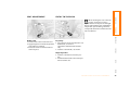
Longitudinal seat adjustment
Seat height
Lumbar support*
1. Lift the handle
2. Push the seat into the desired position
3. After releasing the handle, apply pressure to the seat to ensure that the latch
engages securely.
1. To raise:
Pull the handle up repeatedly,
continuing until the seat reaches the
desired height
2. To lower:
Push the handle repeatedly, continuing
until the seat reaches the desired height.
You can adjust the contour of the backrest
for additional support in the curvature of
your spine's lumbar region.
The upper hips and spinal column receive
supplementary support to help you maintain a relaxed, upright posture.
Make corrections in the longitudinal
adjustment of the seat to ensure that
the safety belt still fits firmly against your
body. If you do not do this, the protection
provided by the safety belt may be
reduced.<
32
Turn the wheel to increase or decrease the
curvature.
Online Edition for Part No. 01 41 0 156 724 - © 01/02 BMW AG
Easy Entry
1. Pull the lever at the inside of the seat
2. Apply weight to or remove weight from
the backrest as required
3. Release the lever so that the backrest
locks into place.
1. Press the lever on the outside of the seat
downwards, see arrow 1.
The backrest folds forward automatically
2. Push the seat forwards, see arrow 2.
Original position
CONTROLS
INDEX
1. Push the seat back into its home position
2. Fold the backrest back to the home position to lock the seat.
OPERATION
Backrest tilt
REPAIRS
When returning the seat to the rear
position, ensure that no one is
injured and that no objects are damaged.
Engage and lock both seats and backrests
into position prior to driving, otherwise
unexpected movement could increase the
risk of accident.<
OVERVIEW
ENTRY TO THE REAR
DATA
SEAT ADJUSTMENT
Online Edition for Part No. 01 41 0 156 724 - © 01/02 BMW AG
33
HEATED SEATS*
HEAD RESTRAINTS
Installation
1. Press the button and at the same time
insert the head restraint in the reception
points
2. Adjust the head restraint.
The seat cushion and backrest can be
heated with the ignition key in position 2.
Select the temperature setting:
To avoid possible violation of
traffic laws, never retract the head
restraints unless the rear seats are empty.
Always ensure that the head restraints are
raised before transporting passengers in
the rear seat.<
Adjusting the head restraints
To raise: pull the head restraint upward.
To lower: press the button and push the
head restraint downward.
Press each button briefly.
Direct deactivation from second temperature setting.
Press the button for a longer period.
You can reduce the risk of spinal
injury and whiplash by adjusting the
head restraint to a height at which it is
centered roughly at ear level.<
Removal
1. Pull up the head restraint, continuing
until it is at maximum extension
2. Press the button and remove the head
restraint at the same time.
34
Online Edition for Part No. 01 41 0 156 724 - © 01/02 BMW AG
STEERING WHEEL
Use the height adjustment mechanism to
adapt the safety belt to the ideal position
for your own body:
Make sure you hear the lock engage in the
belt buckle.
To release
1. Press the red button in the belt buckle
2. Hold the belt
3. Guide the belt back into its reel.
1. Push the locking lever downward
2. Adjust the desired steering wheel
position
3.
Pull the lever back in.
Press the button and at the same time push
the entire unit upwards or downwards.
Do not adjust the steering wheel
Also observe the instructions on adjusting
while the vehicle is moving, otherthe seats on page 31.
wise unexpected movement could increase
the risk of accident.<
If the safety belts are damaged or
stretched in an accident: have the
safety belt system replaced by your MINI
center and the belt anchors checked, otherwise the safety function can no longer be
guaranteed. If a child-restraint system was
in the vehicle during an accident, consult
the manufacturer's instructions regarding
replacement.<
Online Edition for Part No. 01 41 0 156 724 - © 01/02 BMW AG
REPAIRS
Even though there is an airbag, wear a
safety belt every time you get in the
vehicle, because airbags enhance safety by
providing added protection.
To fasten
To adjust the steering wheel height
DATA
Safety belt height adjustment
INDEX
Drive with your safety belt on
OPERATION
CONTROLS
OVERVIEW
SAFETY BELTS
35
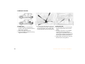
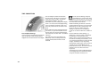
MIRRORS
Manual adjustment
The mirrors can also be adjusted manually:
Press the edge of the lens.
Electric heating*
Both mirrors are heated automatically
when the ignition key is in position 2.
Adjusting exterior mirrors
Interior rearview mirror
1 Switch for choosing between the left and
right mirror
2 Switch for 4-way adjustment.
To reduce glare from vehicles behind you
when you are driving at night:
Tilt the lever forward.
Illuminated vanity mirror
From ignition key position 1:
1. Fold down the sun visor
2. Fold the cover panel upwards.
Sun visors
Can be swung sideways.
36
Online Edition for Part No. 01 41 0 156 724 - © 01/02 BMW AG
AIRBAGS
designed to help support the seat occupant's upper body.
OVERVIEW
MIRRORS
2 Head airbags on the driver and
passenger sides for both rows of seats
(front/rear)
The mirror becomes clear again when you
engage reverse gear or select selector lever
position R.
Do not apply adhesive materials to
the cover panels of the airbags, cover
Keep the photocells free and clean to
them
or modify them in any other way. Do
ensure that the mirror functions perfectly.
not fit covers, cushions or other items to
There is one photocell in the mirror frame; Protective effect
the front seats that have not been specially
the other is on the back of the mirror.
The front airbags supplement the safety
approved for seats with side airbags. Do
belts by helping to provide additional
not hang clothing, e.g. jackets, over the
Do not cover the area between the
protection for the driver and front
inside rearview mirror and the wind- passenger in the event of a frontal collision backrests. Do not attempt to remove the
airbag restraint system from the vehicle. In
shield, and do not place stickers or toll tags in which the protection afforded by the
the event of malfunctions, immobilization
on the windshield in front of the mirror.< belts alone may no longer be sufficient.
or use (triggering) of the airbag restraint
When needed, the head and side airbags
system in accordance with its intended
help to furnish protection in the event of
function, only commission a MINI center
side impact. Each of the side airbags is
with the inspection, repair or disassembly.
3 Front airbags on the driver and
passenger sides
Online Edition for Part No. 01 41 0 156 724 - © 01/02 BMW AG
OPERATION
The mirror dims automatically as required.
REPAIRS
1 Side airbags in seats on the driver and
passenger sides (front)
DATA
Interior rearview mirror, automatic
dimming feature*
Even when all safety guidelines are
observed, there is a small residual risk that
passengers will sustain facial, hand or arm
injuries in isolated instances. The ignition
and inflation noise may induce a mild
temporary hearing loss in sensitive individuals.
INDEX
The airbags do not deploy in response
to minor collisions, rear impacts and
certain kinds of vehicle rollover.<
CONTROLS
For information on sitting posture, refer to
page 31.
37
AIRBAGS
Do not make any changes yourself to the
individual components and wiring. This
includes the padded cover of the steering
wheel, in the instrument panel and the roof
supports, as well as the sides of the roofliner and the original backrest covers on the
front seats. Do not attempt to remove or
dismantle the steering wheel. In view of
the applicable safety regulations, arrange
for your MINI center to dispose of the
airbag generators. Unprofessional
attempts to service the system could lead
to failure in an emergency or undesired
airbag activation, either of which could
result in personal injury. Do not touch the
individual components directly after the
system has been triggered, as otherwise
there is a danger of burns.<
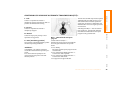
TRANSPORTING CHILDREN
Indicator lamp
The indicator lamp on the instrument panel shows the airbag
system status starting from ignition key position 1.
System operational:
> The indicator lamp comes on briefly.
System malfunction:
> The indicator lamp does not come on
> The indicator lamp fails to go out after
the engine has been started, or it comes
on during normal driving.
A system defect could prevent the airbags
from deploying in response to a severe
impact occurring within the system's
normal triggering range.
Have the system checked as soon as
At all times, occupants should sit
possible by your MINI center.
upright and be properly restrained
(infants and small children in appropriate
child-restraint systems; larger children and
adults using the safety belts). Never let an
occupant's head rest near or on a head
airbag because the inflating airbag could
cause serious or fatal injury. A child which
is not properly restrained could place his or
her head on or near the airbag.<
38
Children younger than 13 years and/or
smaller than 5 ft (150 cm) should only
travel in the rear in suitable restraint
systems.
Commercially-available child-restraint
systems are designed to be secured with a
lap belt or with the lap belt portion of a
combination lap/shoulder belt. Improperly
or inadequately installed restraint systems
can increase the risk of injury to children.
Always read and follow the instructions
that come with the system.
If you use a child-restraint system with a
tether strap:
Online Edition for Part No. 01 41 0 156 724 - © 01/02 BMW AG
Adjust the tether strap according to the
child restraint manufacturer’s instructions.
Anchor fitting 1 is shown above.
Anchor fitting 2 is shown in the next
column.<
Online Edition for Part No. 01 41 0 156 724 - © 01/02 BMW AG
CONTROLS
OPERATION
REPAIRS
DATA
Depending on the location selected for
seating in the rear passenger area, attach
the tether strap to the corresponding
anchorage point to secure the childrestraint system.
Both seating positions are fitted with a
head restraint. Lift the head restraint and
pass the tether strap between the head
restraint and the seat back. It is recommended to readjust the head restraint into
the lowest possible position.
INDEX
Your vehicle has one of two different types
of child-restraint anchor fittings on the
back of the rear seats, see arrows 1 or 2.
Adjust the tether strap according to
the child restraint manufacturer's
instructions. Before installing any childrestraint device or child seat, please read
the following:
Never install a rearward-facing childrestraint system in the front passenger seat
of this vehicle.
Your vehicle is equipped with an airbag
supplemental restraint system for the front
passenger. Because the backrest on any
rearward-facing child-restraint system –
of the kind designed for infants under
1 year and 20 Ibs./9 kg – would be within
the airbag's deployment range, you should
never mount such a device in the front
passenger seat, since the impact of the
airbag against the child restraint's backrest
could lead to serious or fatal injuries.
If it is necessary for a child – not an infant –
to ride in the front seat, certain precautions
should be taken. First, move the passenger
seat as far away from the instrument panel
as possible. This important precaution is
intended to maximize the distance
between the airbag and the child. Older
children should be tightly secured with a
safety belt, after they have outgrown a
booster seat that is appropriate for their
age, height and weight. Younger children
should be secured in an appropriate
OVERVIEW
TRANSPORTING CHILDREN SAFELY
39
TRANSPORTING CHILDREN SAFELY
forward-facing child-restraint system that
has first been properly secured with a
safety belt. Never install a rearward-facing
child-restraint system in the front
passenger seat.
We strongly urge you to carefully read and
comply with the instructions for installation and use provided by the child
restraint's manufacturer whenever you use
such a device.
Be sure that all occupants – of all ages –
remain properly and securely restrained at
all times.
According to accident statistics, children
are safer when properly restrained in the
rear seats than in the front seating positions.<
To lock the belt
Pull the entire length of the belt from the
belt retractor. Allow the reel to retract the
belt somewhat and engage the buckle,
then tighten the belt against the childrestraint system. The retraction mechanism is now locked.
To unlock the belt
Release the buckle, remove the childrestraint system and allow the belt
retractor to reel the belt completely in.
Child seat security
All of the rear belt retractors and the front
passenger's safety belt can be locked for
mounting and securing child-restraint
systems.
Information regarding this is located near
All rear seats in your vehicle conform to the the buckle latch of each safety belt.
guidelines defined in SAE J1819, an
industry recommended practice for
securing child-restraint systems in motor
vehicles.
40
Online Edition for Part No. 01 41 0 156 724 - © 01/02 BMW AG
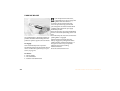
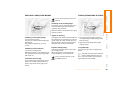
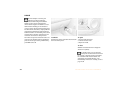
The illustration is an example showing
the mounts for the LATCH (Lower Anchors
and Tethers for Children) child-restraint
mounting system at the right rear.
The system is also available at the left rear
position.
Always follow all manufacturer's
instructions and observe all safety
precautions when installing the LATCH
child-restraint system.<
CONTROLS
OPERATION
Open the cover.
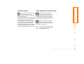
INDEX
LATCH child-restraint system
> Automatic activation of windshield
wipers on cleaning
Doubtless you have often reflected on how
> "Follow me home" lamps
great it would be if you could configure
Low beams light up for a short time after
your vehicle's various adjustment settings
the engine has been switched off
to meet your own personal requirements.
> Locking when engine is running (with
In developing this vehicle, the manufacsecond key)
turer has incorporated a number of options
>
Stop function of power windows on
that your MINI center can program to
opening/closing
reflect your individual preferences.
> Activating/deactivating daytime driving
lamps*
What the system can do
> Switching on interior lamps via remote
Your MINI center can provide you with
control.
details on the capabilities of the Vehicle
Memory system.
This symbol draws your attention to
Examples for Vehicle Memory:
other Vehicle Memory functions
described in the Owner's Manual.<
> Signals an acknowledgement when
locking or unlocking your vehicle
> Automatic locking after starting off
> Automatic unlocking when the parking
brake is applied
> Selective central locking
First open the driver's door, then the
whole car
> Automatic opening/closing of sliding/tilt
sunroof
> Opening/closing windows and/or
sliding/tilt sunroof via remote control
> Speed-dependent windshield wiper
REPAIRS
How the system functions
OVERVIEW
VEHICLE MEMORY
DATA
TRANSPORTING CHILDREN
Online Edition for Part No. 01 41 0 156 724 - © 01/02 BMW AG
41
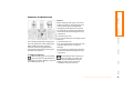
IGNITION LOCK
STARTING THE ENGINE
Vehicles with Continuously Variable
automatic Transmission (CVT):
Do not move the selector lever from position "P" until the engine is running.
Your vehicle is equipped with an interlock.
Therefore, the ignition key cannot be
turned to position 0 and removed until the
selector lever is in position "P" (Interlock).<
0
1
2
3
Steering locked
Steering unlocked
Ignition switched on
Starting the engine
0 Steering locked
The key can be inserted or removed in this
position only.
To lock the steering:
1. Remove the key
2. Turn the steering wheel slightly to the
left or right until the lock engages.
42
Do not allow the engine to warm up with
the vehicle at a standstill. Move off immediately at a moderate engine speed.
Do not allow the engine to run in
enclosed spaces. The exhaust gases
contain carbon monoxide, an odorless and
colorless, but highly toxic gas.
Breathing the exhaust gases poses an
extreme health risk, and can lead to uncon1 Steering unlocked
sciousness and death.
Individual electrical accessories are ready
Do not leave the vehicle unattended with
for operation.
the engine running. An unattended vehicle
You will find that it is often easier to turn
with a running engine represents a potenthe ignition key from position 0 to positial safety hazard. When driving, standing
tion 1 when you move the steering wheel
at idle or when parking, take precautions to
slightly to help disengage the lock.
avoid contact between the hot exhaust
system and easily flammable materials
2 Ignition switched on
(grass, hay or leaves, for example). Such
All electrical accessories are ready for oper- contact could lead to a fire, resulting in
ation.
serious personal injury and property
damage.<
3 Starting the engine
Vehicles with manual transmission:
Step on the clutch when starting the
vehicle. A lockout prevents the engine from
starting if the clutch is not depressed.<
Online Edition for Part No. 01 41 0 156 724 - © 01/02 BMW AG
1.
2.
3.
4.
Do not actuate the starter for too
short a time. Do not turn it for more
than approx. 20 seconds. Release the ignition key immediately when the engine
starts.
Extended starting attempts, characterized
by excessively frequent or long periods
with the starter engaged, can lead to
damage in the catalytic converter.<
If the engine does not start on the first
attempt (the engine is very hot or cold, for
instance):
> Press the accelerator pedal halfway
down while engaging the starter.
Cold starts at extremely low temperatures
(as of approx. +5 7(–15 6)):
You should never remove the ignition
key when the vehicle is in motion, as
Engage the parking brake
Put the manual gearshift lever in neutral the steering lock could engage.
When you leave the vehicle, always remove
Press the clutch pedal
the ignition key and engage the steering
Start the engine.
lock.
When you park on downward slopes,
Continuously Variable automatic
engage the parking brake.<
Transmission (CVT)*
1. Press the footbrake
2. Put the selector lever in position P or N
3. Starting the engine.
Move the selector lever to position N
and engage the parking brake before
leaving your vehicle with the engine
running.
Do not leave the vehicle with the engine
running. An unattended vehicle with a
running engine represents a potential
safety hazard.<
CONTROLS
Manual transmission
When starting the engine, do not press the
accelerator pedal.
Manual transmission
Turn the ignition key to position 1 or 0.
Continuously Variable automatic
Transmission (CVT)*
OPERATION
Starting
OVERVIEW
SWITCHING OFF THE ENGINE
Engage selector lever position P, turn the
ignition key to position 1 or 0.
INDEX
DATA
> Press the accelerator pedal halfway
down while engaging the starter
> For the initial start attempt, allow the
starter to remain engaged somewhat
longer (approx. 10 seconds).
REPAIRS
STARTING THE ENGINE
Online Edition for Part No. 01 41 0 156 724 - © 01/02 BMW AG
43
PARKING BRAKE
If, in exceptional circumstances,
it should be necessary to engage the
parking brake while the vehicle is
in motion, do not pull the lever with
excessive pressure. Keep your thumb
pressed against the release button while
carefully pulling the lever up to apply
moderate pressure.
Excessive pressure can lead to overbraking
and loss of traction (fishtailing) at the rear
axle.
The brake lamps do not come on when the
The parking brake is designed primarily to parking brake is engaged.
prevent the vehicle from rolling when it is Vehicles with manual transmission:
parked. It operates against the rear wheels. Always engage the parking brake when
parking on hills and inclined surfaces, as
To engage
first gear or reverse may not provide
adequate resistance to rolling.
Lever automatically locks in position.
The warning lamp in the instrument cluster Vehicles with CVT:
comes on when the ignition key is in posi- Place the selector lever in P.<
tion 2, see page 16.
To release
1. Pull up slightly
2. Press the button
3. Push the lever downwards.
44
Online Edition for Part No. 01 41 0 156 724 - © 01/02 BMW AG
5-speed transmission:
Press the gearshift lever to the right and to
the back.
The manual gearshift lever neutral plane
lies in the gear plane of the 3rd/4th gear.
When shifting from each gear into
"Neutral", the manual gearshift lever
springs back automatically into the gearshift lever neutral plane.
6-speed transmission:
Press the gearshift lever to the left to overcome the slight resistance and press
forwards.
As you do this, the backup lamps will turn
on automatically when the ignition key is
in position 2.
6-speed transmission*
Do not hold the vehicle in place on
slopes by slipping or "riding" the
clutch. Use the parking brake instead.
Riding the clutch causes the clutch
assembly to wear out sooner.<
CONTROLS
INDEX
When changing gear in the 5th/6th
gear plane, press the gearshift lever
to the right to prevent shifting to a gear of
the 3rd/4th gear plane.<
OPERATION
As you do this, the backup lamps will turn
on automatically when the ignition key is
in position 2.
REPAIRS
Before selecting reverse gear, ensure the
vehicle is stationary; then, fully press the
clutch pedal and pause briefly before
moving the gearshift lever into position.
DATA
Reverse
OVERVIEW
MANUAL TRANSMISSION
Online Edition for Part No. 01 41 0 156 724 - © 01/02 BMW AG
45
CONTINUOUSLY VARIABLE AUTOMATIC TRANSMISSION (CVT) *
You can drive with a steplessly shifting CVT.
In addition, you can also shift manually.
While the vehicle is stationary and
before shifting out of P or N, press
the brake pedal in order to disengage the
selector lever lock mechanism (Shiftlock).
If the engine speed is too high when the
vehicle is at a standstill, the selector lever
is also blocked to protect the transmission.
Hold the brake pedal down until starting
off. Otherwise the vehicle will "creep" when
a drive position is engaged.<
When you move the selector lever from the
D position to the right into the M/S + –
range, the performance-oriented shift
programs of the CVT are engaged. Steptronic enters the manual selection mode
and executes the desired shift whenever
you tap the selector lever in the direction
indicated by "+" or "–" .
Whenever you want to use automatic
again, just move the selector lever toward
the left to position D.
In positition D, you achieve the
lowest fuel consumption for average
driving.<
Selector lever positions
P R N D M/S + –
Range selection
Inadvertent engaging of certain selector
lever positions is prevented by a lock.
Press the button on the front side of the
selector lever knob. The lock is released.
To prevent the vehicle from starting
off on its own, always move the
selector lever to position P or N and engage
the parking brake before leaving your
vehicle with the engine running.
Do not leave the vehicle unattended with
the engine running. An unattended vehicle
with a running engine represents a potential safety hazard.<
If the selector lever is not placed in
position P when the vehicle is parked,
the position display of the selector lever
stays on. This can lead to battery
discharge.<
46
Online Edition for Part No. 01 41 0 156 724 - © 01/02 BMW AG
N Neutral
D Drive (CVT driving position)
This position is designed for driving under
all normal operating conditions.
"Kickdown"
In "kickdown", you achieve maximum
acceleration and maximum speed in position D.
Press the accelerator pedal past the
increased resistance point at the fullthrottle position.
M/S + – Manual mode and Sport
program
Switch from D into M/S + –:
Activates the Sport program and indicates
SD in the gear indicator in the speedometer.
> Press briefly:
CVT shifts from the Sport program to the
manual mode
> Press selector lever briefly towards "+":
Transmission shifts upwards
> Press selector lever briefly towards "–":
Transmission shifts back.
1 to 6 appear in the gear indicator.
INDEX
Select "N" only if your journey is interrupted for a long period.
CONTROLS
Switching from M/S + – into the selector
lever positions P, R and N and switching
from manual mode back into the Sport
program is only possible via D.
Select "R" only when the vehicle is
completely stopped.
OPERATION
R Reverse
REPAIRS
The transmission will only execute upshifts
and downshifts that will result in a plausible combination of vehicle speed and
engine rpm, forinstance, downshifts that
would result in excessive engine speed are
not executed.
Select "P" only when the vehicle is
completely stopped. Transmission locks to
prevent rear wheels from turning.
DATA
P Park
OVERVIEW
CONTINUOUSLY VARIABLE AUTOMATIC TRANSMISSION (CVT) *
Online Edition for Part No. 01 41 0 156 724 - © 01/02 BMW AG
47
CONTINUOUSLY VARIABLE AUTOMATIC TRANSMISSION (CVT) *
Do not work in the engine compartment when a drive gear (forward or
reverse) is engaged. If you do this, the
vehicle could move.<
Jump-starting and towing, refer to
pages 113, 115.<
Available displays
P R N D SD 1 2 3 4 5 6 EP
Electronic transmission control module
If there is a malfunction in the transmission
system, EP appears in the display.
All selector lever positions can still be
selected. In positions for driving forward:
The vehicle can now only be driven with a
limited gear selection.
Avoid high engine loads. Proceed to
the nearest MINI center.<
48
Online Edition for Part No. 01 41 0 156 724 - © 01/02 BMW AG
SIGNAL/HEADLAMP FLASHER
OVERVIEW
PARKING LAMPS/LOW BEAMS
You can also have this function activated.<
Switching on the standing lamps
"Lights on" warning
Switching on the parking lamps
Turn to the first position.
The front, rear and side vehicle lighting is
switched on.
One-sided standing lamps, see next
column.
Switching on the low beams
Turn to the second position.
With the low beams on and with the ignition switched off, only the parking lamps
will remain on.
"Follow me home" lamps
If the lights have not been switched off and 1 Turn signal indicator (green indicator
accompanied by periodic clicking sound
the ignition key is in position 0, an acoustic
from the relay)
signal sounds for a few seconds when you
open the driver's door to remind you that
2 High beams/Headlamp flasher (blue
the lights have not been switched off.
indicator lamp)
Daytime driving lamps*
To signal briefly
If you desire, the light switch can be left in
the second position:
When the ignition is switched off, the
external lighting is also switched off.
Press the lever up to but not beyond the
detent.
You can have this function set by
your MINI center.<
If the indicator lamp of the indicators
and the clicking from the relay are
both faster than normal: one of the turn
signal indicators has failed.<
INDEX
If you switch off the engine with the low
beams on, and then switch off the low
beams, they remain lit for approx. one
minute.
REPAIRS
Move the lever into the relevant turn signal
indicator position.
DATA
In ignition key position 0:
OPERATION
CONTROLS
For parking, you can activate lights on one
side of the vehicle (observe local laws).
Online Edition for Part No. 01 41 0 156 724 - © 01/02 BMW AG
49
INSTRUMENT LIGHTING
FOG LAMPS
INTERIOR LAMPS
To control the instrument lighting, press
the button.
When the parking lamps/low beams are
switched on:
Switching the interior lamps on and
off manually
Briefly press the switch upwards or downwards.
Press button 1.
To increase the illumination intensity
Keep the button pressed until the desired
brightness is reached.
Briefly press once again to switch off.
Switching the reading lamps on and
off
Fog lamps*
Press button 2.
To decrease the illumination intensity
Press the button briefly.
With each brief press of the button, the
illumination intensity is reduced in steps.
Fog lamps switched on:
Green light-emitting diode in the
switch lights up.
The fog lamps are deactivated whenever
the high beams are switched on.
50
Online Edition for Part No. 01 41 0 156 724 - © 01/02 BMW AG
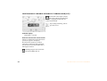
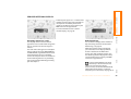
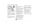
The rain sensor is located on the windshield, directly in front of the interior rearview mirror. When the rain sensor is
activated, the windshield wipers are automatically controlled depending on the
amount of water (or snow) landing on the
windshield.
Do not remove the protective lens
and avoid staring directly at the unfiltered beam for several hours, as inflammation of the iris could result.<
CONTROLS
Rain sensor*
Light-emitting diodes (LEDs) installed
behind translucent lenses serve as the light
source for many of the controls and
displays in your vehicle. These light-emitting diodes are related to conventional
lasers, and legislation defines them as
"light-emitting diodes, Class 1".
OVERVIEW
WASHER/WIPER SYSTEM
From ignition key position 1:
Lever in position 1.
The wipers move across the windshield
once.
To deactivate the rain sensor:
Put lever in position 0.
Switch the rain sensor off when
passing through an automatic car
Intermittent operation
wash. Failure to do so could result in
(not on vehicles with rain sensor)
damage caused by undesired wiper activaThe interval varies depending on the speed tion.<
being driven.
You can have this function set by
your MINI center.<
Fast wiper speed
When the vehicle is stationary, the wipers
switch automatically to normal wiper
speed.
You can have this function activated/
deactivated by your MINI center.<
Online Edition for Part No. 01 41 0 156 724 - © 01/02 BMW AG
REPAIRS
Wipers parked
Intermittent operation or rain sensor
Normal wiper speed
Fast wiper speed
Brief wipe
Clean windshield and headlamps
DATA
0
1
2
3
4
5
OPERATION
To activate the rain sensor:
INDEX
LIGHT-EMITTING DIODES
51
WASHER/WIPER SYSTEM
Cleaning windshield and headlamps*
The system sprays washer fluid against the
windshield. The wipers are automatically
activated for a brief period.
When the vehicle lighting is on, the headlamps are also cleaned at appropriate intervals.
Do not use the washers if there is any
danger that the fluid will freeze on
the windshield. If you do so, your vision
could be obscured. For this reason, use an
Rear window wiper
antifreeze agent, see page 89.
6 Intermittent operation:
Do not use the washers when the reservoir
Turn the cap to position 6
is empty, since this could cause damage to
The rear window wiper moves across the
the washing pump.<
window a number of times before
switching to intermittent operation
Windshield washer jets*
The windshield washer jets are heated
automatically when the ignition key is in
position 2.
Cleaning the rear window
7 Intermittent operation:
Turn the cap to position 7 and hold in
place
8 In lever position 0:
Turn the cap to position 8 and hold in
place
52
Online Edition for Part No. 01 41 0 156 724 - © 01/02 BMW AG
If you are already driving with active cruise
control, the speed is decreased by approx.
1 mph (2 km/h) every time you briefly tap
the button.
The indicator lamp in the instrument
cluster lights up.
Cruise control is active.
Press and hold button 4.
To maintain and store speed or to
accelerate
Press button 3.
Do not use cruise control on twisting
roads, when high traffic density
prevents driving at a constant speed, when
the road surface is slick (snow, rain, ice), or
when the road surface is loose (rocks,
sand).<
The system maintains and stores the
current vehicle speed. Every time you tap
the button, the speed increases by approx.
1 mph (2 km/h).
Press and hold button 3.
The vehicle accelerates without pressure on
the accelerator pedal. When you release
the button, the system maintains and
stores the current speed.
If, on a downhill gradient, the engine
braking effect is not sufficient, the
controlled speed may be exceeded. Speed
can drop on uphill grades if the engine
output is insufficient.<
INDEX
Starting at about 25 mph (40 km/h), the
vehicle maintains and stores any vehicle
speed that you specify.
With the cruise control active, the system
automatically reduces the throttle opening
to slow the vehicle. When you release the
button, the system maintains and stores
the current speed.
CONTROLS
Press button 2.
OPERATION
Press button 4.
REPAIRS
To decelerate
From ignition key position 1:
DATA
To activate the system
OVERVIEW
CRUISE CONTROL*
Online Edition for Part No. 01 41 0 156 724 - © 01/02 BMW AG
53
CRUISE CONTROL*
To cancel the cruise control
To continue cruise control
When the system is activated, press
button 2.
Press button 1.
The indicator lamp stays lit.
You can use the cruise control again as
required.
The vehicle accelerates to and maintains
the last speed stored. If you turn the ignition key to position 0, the stored speed is
deleted and the system is deactivated.
In addition, cruise control is canceled automatically
To deactivate the system
> if the brakes are applied
> when you apply pressure to the clutch
pedal, or when you move the CVT
selector lever from D to P, N or R
> or if the cruise speed is either exceeded
or not met for an extended length of
time (if you press the accelerator pedal
and exceed the stored speed, for
example).
54
With cancelled cruise control, press
button 2 once again.
The indicator lamp goes out and the stored
speed is deleted.
Online Edition for Part No. 01 41 0 156 724 - © 01/02 BMW AG
TACHOMETER
FUEL GAUGE
1 Trip odometer
Do not operate the engine with the needle
in the red overspeed zone of the gauge.
In the speedometer
You can activate the displays shown in the
illustration with the ignition key in position 0 by pressing the button in the instrument cluster.
When you switch on the ignition, the indicator lamp lights up briefly to confirm that
the system is operational.
If the tilt of the vehicle varies (when you
are driving in mountainous areas, for
example), the needle may fluctuate
slightly.
Please refuel early, since driving to
the last drop of fuel can result in
damage to the engine and/or catalytic
converter.<
Online Edition for Part No. 01 41 0 156 724 - © 01/02 BMW AG
REPAIRS
2 Odometer
Once indicator lamp 1 stays on continuTo protect the engine, the power is reduced ously, there are still approx. 2.1 gallons
when you approach a certain engine speed (8 liters) of fuel in the fuel tank.
Tank capacity: approx. 13.2 gallons
in this sector.
(50 liters).
DATA
With ignition key in position 1, press the
button until the trip odometer is at zero.
INDEX
To set to zero:
OPERATION
CONTROLS
OVERVIEW
ODOMETER
55
FUEL GAUGE
TEMPERATURE GAUGE
1 Red indicator lamp
When you switch on the ignition, warning
lamp 1 comes on briefly to confirm that the
system is operational.
If the lamp comes on while operating the
vehicle, the engine has overheated. Switch
off the engine immediately and allow it to
cool down.
Navigation system option
In the navigation system
Please also comply with the instructions in the previous column.<
Once indicator lamp 1 switches from
orange to red, there are still approx.
2.1 gallons (8 liters) of fuel in the fuel tank.
Low temperature
The needle is located at the bottom or on
the right.
The engine is still cold. Drive at moderate
engine and vehicle speeds.
Coolant temperature warning
lamp in the tachometer.
If the lamp comes on while operating the vehicle, the engine has overheated. Switch off the engine immediately
and allow it to cool down.
Center position
Normal operating temperature of the
engine.
High temperature
As soon as there is a deviation from the
center position upwards or to the left:
Drive moderately and at low engine speed,
if necessary, switch off the engine and
allow to cool down.
Checking coolant level, see page 91.
56
Online Edition for Part No. 01 41 0 156 724 - © 01/02 BMW AG
OVERVIEW
SERVICE INTERVAL DISPLAY
The displays shown in the illustration
appear for a few seconds when the ignition
key is in position 1 or after the engine is
started.
You can obtain a display of the number of
days remaining until the next due brake
fluid change, see page 92.
The next service due appears in miles (kilometers) with the message INSPECTION or/
and OILSERVICE, together with the distance
remaining before the next scheduled
service. The computer bases its calculations
of the remaining distance on your driving
style in the period immediately preceding
your data request.
While the next due service is displayed,
press the button in the display element.
As of the due date of the brake fluid
change, the clock symbol also lights up in
the remaining distance display for Service,
see left column. Please contact your MINI
center for an appointment.
Periods of immobilization in which
the battery is disconnected are not
taken into account by the display.
For this reason, ensure that the brake fluid,
independent of the display, is replaced
every two years at the latest, see page 92.<
Online Edition for Part No. 01 41 0 156 724 - © 01/02 BMW AG
REPAIRS
Brake fluid change
DATA
Remaining distance for service
INDEX
For more information on the Service
Interval Display, see page 93.
OPERATION
CONTROLS
A flashing message and a "–" in front of the
number mean that the service interval has
already been exceeded by the distance
shown on the display. Please contact your
MINI center for an appointment.
57
CLOCK
COMPUTER*
The displays appear in the following order:
Outside temperature, cruising range,
average fuel consumption, average vehicle
speed.
Starting with ignition key position 1, the
last active setting is displayed.
If the vehicle is equipped with a navigation system, see chapter covering
the computer in the navigation system
Owner's Manual.<
Settings
Mode selection
From ignition key position 1:
With the ignition key in position 1 and
higher, you can use the button in the turn
signal indicator lever to retrieve information from the computer for display in the
tachometer. By pressing the button briefly,
you can call up a new function for display.
Left button: hours
Right button: minutes
Move forward in increments:
Press the button
or
Fast forward:
Press and hold the button
Changeover from 24-hour to 12-hour
mode:
Press both buttons at the same time for
approx. 5 seconds.
58
Online Edition for Part No. 01 41 0 156 724 - © 01/02 BMW AG
OVERVIEW
COMPUTER*
Average speed –
Average fuel consumption
The average speed value/consumption
value on display is recalculated.
OPERATION
Any time spent when the vehicle is
stationary and the engine is switched off
is ignored for the calculation.
CONTROLS
Press the button in the turn signal indicator
lever for a longer period.
Outside temperature
REPAIRS
If the vehicle is equipped with a tachometer, but not with a computer, the
temperature is always displayed.
You can display the exterior temperature and distance driven in other
units of measurement.<
Cruising range
INDEX
DATA
The computer bases its calculations for the
cruising range on the driving style and on
the remaining fuel in the tank.
Online Edition for Part No. 01 41 0 156 724 - © 01/02 BMW AG
59
AUTOMATIC STABILITY CONTROL PLUS TRACTION (ASC+T) *
The concept
Indicator lamp
This system optimizes vehicle stability and
traction, especially when just starting off,
when accelerating or when cornering.
ASC+T recognizes the danger present in
traction loss and will increase driving
stability and traction by reducing the
engine's output, and if necessary, by
applying the brakes to the front wheels.
ASC+T is operational each time you start
the engine.
The indicator lamp on the instrument cluster will go out shortly
after the ignition has been
switched on, see pages 16, 17.
If the indicator lamp flashes:
ASC+T controls the drive and braking
forces.
If the indicator lamp fails to go out
after the engine is started, or if it
comes
on during normal driving and stays
Switch off the ASC+T
The laws of physics cannot be
on:
repealed, even with ASC+T. An appro- Briefly press the switch.
If the system is either defective or was
priate driving style always remains the
The indicator lamp stays lit.
switched off with the button, then the
responsibility of the driver. Avoid using the When driving with snow chains or to "rock stabilizing applications described are no
additional safety margin provided by the
free" in snow, it can be helpful to switch off longer available. You can, however, drive
system as an excuse for taking unnecessary the ASC+T for a brief period.
the vehicle normally without ASC+T.
risks.
In the event of a malfunction, please see
Do not make any modifications to the
To maintain vehicle stability, always your MINI center, see pages 16, 17.<
ASC+T system. Allow only authorized techdrive with the ASC+T switched on
nicians to perform service procedures on
whenever possible.<
the ASC+T.<
Switch the ASC+T back on
Briefly press the switch once again.
Indicator lamp goes out.
60
Online Edition for Part No. 01 41 0 156 724 - © 01/02 BMW AG
To switch off the DSC
Briefly press the switch.
The DSC is operational every time you start
The indicator lamp stays lit.
the engine. DSC contains the functions
Antilock Brake System ABS/Electronic Brake When driving with snow chains, it may be
effective to switch off the DSC for a brief
Force Distribution EBV/ASC+T.
period.
The laws of physics cannot be
To maintain stability, always drive
repealed, even with DSC. An approwith the DSC switched on whenever
priate driving style always remains the
possible.<
responsibility of the driver. We therefore
urge you to avoid using the additional
To switch DSC back on
safety margin of the system as an excuse
for taking risks.
Briefly press the switch once again.
Do not make any modifications to the DSC Indicator lamp goes out.
system. Allow only authorized technicians
to perform service procedures on the
DSC.<
If the indicator lamp fails to go out
after the engine is started, or if it
comes on during normal driving and stays
on:
If the system is either defective or was
switched off with the button, then the
stabilizing applications described are no
longer available. The vehicle will remain
completely operational, however, without
DSC.
In the event of a malfunction, please see
your MINI center, see pages 16, 17.<
Online Edition for Part No. 01 41 0 156 724 - © 01/02 BMW AG
CONTROLS
If the indicator lamp flashes:
DSC controls the drive and braking forces.
OPERATION
The system optimizes vehicle stability
during acceleration and when starting
from a full stop, as well as optimizing traction. In addition, it recognizes unstable
vehicle conditions, such as under- or oversteering, and, as far as is possible within
the laws of physics, helps keeping the
vehicle on a steady course by reducing the
rpms and brake applications to the individual wheels.
REPAIRS
The indicator lamp on the instrument cluster will go out shortly
after the ignition has been
switched on, see pages 16, 17.
DATA
Indicator lamp
INDEX
The concept
This system maintains driving stability
even in critical driving situations.
OVERVIEW
DYNAMIC STABILITY CONTROL (DSC) *
61
FLAT TIRE MONITOR
The concept
Flat tire
The tire inflation pressure is determined
The indicator lamp in the instrufrom the signals of the ABS sensors.
ment cluster informs you by
The system provides an alert whenever the
flashing when the tire inflation
tire inflation pressure drops below the
pressure of a tire drops in relation to any
pressure in any other tire.
other tire. In addition, an acoustic signal is
sounded.
Requirement
So that the system can "familiarize" itself
with the correct inflation pressure, please
do the following:
1. Check the tire inflation pressure in all
tires
2. Compare them with the inflation pressure table, see page 81, and adjust the
pressures if necessary
3. Initialize the system.
Check the tire inflation pressure
regularly and correct it if necessary,
see page 80.<
> Vehicles with safety (run-flat) tires, see
notes on pages 110, 80, 84
> Vehicles with normal tires, see notes on
pages 106, 80.
The Flat Tire Monitor cannot alert you
to severe and sudden tire damage
caused by external factors. Another factor
which the Flat Tire Monitor does not recognize is the balanced and very gradual pressure loss that takes place in all tires over an
extended period of time.<
Malfunctions
As long as there is still a malfunction, the
yellow indicator lamp on the instrument
cluster will stay lit up.
The indicator lamp also lights up in the
event of a system malfunction.
Initializing the system
Only initialize the system if the inflation
pressure, e. g. after a tire change, has been
corrected.
1. Ignition key in position 2
2. Press the button long enough for the
yellow indicator lamp in the instrument
cluster to light up for a few seconds
3. Start the engine.
After a few minutes driving time, the Flat
Tire Monitor sets the current inflation pressure in the tires as the target values to be
monitored.
Please contact your MINI center in these
cases.
62
Online Edition for Part No. 01 41 0 156 724 - © 01/02 BMW AG
> When driving on roads covered with
snow or on other slippery road surfaces
> A sporty driving style (slip at the driven
wheels, high lateral accelerations).<
The system starts to operate automatically
about one second after you select reverse
with the ignition key in position 2. PDC is
deactivated when you shift back out of
reverse.
Acoustical signals
The distance to the nearest object is indicated by a tone sounding at various intervals. As the distance between vehicle and
object decreases, the intervals between the
tones become shorter. A continuous tone
indicates the presence of an object less
than 9 in (20 cm) away.
Even with PDC, final responsibility for
estimating the distance between the
vehicle and any obstructions always
remains with the driver. Even when sensors
are involved, there is a blind spot in which
objects cannot be detected. Moreover, the
detection of obstructions can approach the
physical limits of ultrasonic measurement,
as occurs e. g. in the case of thin and
wedge-shaped objects.
Certain sources of sound, such as a loud
radio, could drown out the PDC signal
tone.<
Keep the sensors clean and free of ice
or snow in order to ensure that they
will continue to operate effectively.
Do not apply high pressure spray to the
sensors for a prolonged period of time.
Always maintain a distance of more than
4 in (10 cm).<
The warning signal is canceled after
approx. three seconds if the distance to the
obstacle remains constant during this time
(if you are moving parallel to a wall, for
instance).
Online Edition for Part No. 01 41 0 156 724 - © 01/02 BMW AG
OVERVIEW
System malfunctions will be indicated by
a continuous high-pitched tone when the
system is activated the first time. Please
have your MINI center resolve the problem.
CONTROLS
In the following situations false
alarms can also occur under certain
circumstances or the detection of inflation
pressure loss can be delayed:
The PDC assists you when you back into a
parking space. A signal warns you of the
distance to an obstacle. To do this, four
ultrasonic sensors in the rear bumper
measure the distance to the nearest object.
The range for the sensors located at both
rear corners ends approx. 2 ft (60 cm)
behind the bumpers. The range for the two
middle sensors is slightly less than 5 ft
(1.5 meters).
OPERATION
The concept
REPAIRS
Do not initialize the system when
snow chains are fitted. When driving
with snow chains, false alarms can occur or
pressure losses might not be detected.<
DATA
PARK DISTANCE CONTROL (PDC)*
INDEX
FLAT TIRE MONITOR
63
AIR CONDITIONER SYSTEM
64
1 Air onto the windshield and onto the
side windows
4 Temperature 65
5 Windshield heating 65
9 Recirculated-air mode 65
2 Air for the upper body area 66
6 Blower for air supply 65
10 Rear window defroster 65
3 Air for the front and rear footwells
7 Air conditioner 65
8 Air distribution
Online Edition for Part No. 01 41 0 156 724 - © 01/02 BMW AG
Air distribution in upper body
region , upper body region
and footwell , footwell ,
footwell and windows
and
windows .
All intermediate positions are possible, see
illustration and overview on page 64.
Indicator lamp goes out.
The heating continues to run with reduced
power output and then switches itself off
automatically.
Condensation forms in the air conditioner system during operation, and
then exits under the vehicle. Traces of
condensed water under the vehicle are
therefore normal.<
Recirculated-air mode
Supply of outside air into the
vehicle is blocked: indicator lamp
lights up.
The air within the vehicle is recirculated.
Do not run the recirculated-air mode
for longer than approx. 30 minutes,
as otherwise the air quality in the interior
will deteriorate.<
If the windows fog over in the recirculated-air mode, switch the recirculated-air mode off and increase the air
supply as required.<
Online Edition for Part No. 01 41 0 156 724 - © 01/02 BMW AG
CONTROLS
Indicator lamp goes out.
The heating continues to run with reduced
power output and then switches itself off
Temperature
Turn to the right (red) to increase automatically.
the temperature of the
Windshield heating*
passenger compartment.
Windshield heating switched on:
Rapid heating: turn to the
Indicator lamp lights up.
extreme right. Then select a pleasant inteAs long as the indicator lamp is
rior temperature.
lit, the heating operates at high power
output (rapid defrosting).
Air distribution
OPERATION
tion 1.
Air conditioner operation
switched on:
Indicator lamp lights up.
The air is cooled and dehumidified and –
depending on the temperature setting –
rewarmed.
After the engine start, the windshield can
fog over briefly.
REPAIRS
Air conditioner
DATA
Rear window defroster
You can select blower speeds
Rear window defroster switched
from 1 to 4. Position 0: blower is
on:
switched off. The button for
Indicator lamp lights up.
recirculated-air mode fully blocks As long as the indicator lamp is lit, the
the supply of air from outside.
heating operates at high power output
Heating and ventilation operate as of posi- (rapid defrosting).
INDEX
Air supply
OVERVIEW
AIR CONDITIONER SYSTEM
65
AIR CONDITIONER SYSTEM
Microfilter
The microfilter removes dust and pollen
from the incoming air.
Your MINI center will replace it during
routine maintenance. A substantial reduction in the air supply indicates that the
filter must be replaced before scheduled
maintenance.
Draft-free ventilation
Air supply for the upper body area:
Button 1: open and close the vent outlets
as required by turning.
The points indicate the position in each
case.
Vent 2: change the direction of the airflow
by swiveling.
66
Defrosting and demisting the
windshield and side windows
1. Set the rotary blower speed control for
the airflow rate to position 4
2. Turn the rotary temperature control
completely to the right (red)
3. Rotary control for air distribution in position
4. To defrost the rear window: switch on
the rear window defroster and, if
required, the windshield heating.
Online Edition for Part No. 01 41 0 156 724 - © 01/02 BMW AG
REPAIRS
OPERATION
CONTROLS
OVERVIEW
AUTOMATIC CLIMATE CONTROL*
1 Air onto the windshield and onto the
side windows
5 Interior temperature sensor – please
keep clear and unobstructed
2 Air for the upper body area, see page 69
6 Recirculated-air mode 68
11 Display for temperature and air
supply 68
3 Air for the front and rear footwells
7 Air conditioner 68
12 Blower for air supply 69
4 Rear window and windshield
heating 68
8 Automatic air distribution and
supply 68
13 Defrosting and demisting the
windshield and side windows 69
9 Switching the automatic climate
control on/off 68
14 Individual air distribution 69
Online Edition for Part No. 01 41 0 156 724 - © 01/02 BMW AG
INDEX
DATA
10 Temperature 68
67
AUTOMATIC CLIMATE CONTROL*
Automatic air distribution and supply
Automatic program (AUTO):
Indicator lamp lights up.
Automatic adjustment of the air distribution and the air supply and adaptation of
the specified temperatures to external
influences (outside temperature and
sunlight).
In the automatic program (AUTO), the air
conditioner is activated automatically.
Switching the automatic climate
control on/off
The blower, heating and air conditioner are switched off.
After the engine start, the windshield can
Rear window defroster and windshield
fog over briefly. Switching on the air condi- heating*
tioner reduces condensation on the
Rear window defroster and windwindows.
shield heating switched on:
Condensation forms in the air conditioner system during operation, and
then exits under the vehicle. Traces of
condensed water under the vehicle are
therefore normal.<
Recirculated-air mode
Supply of outside air into the
vehicle is blocked:
Indicator lamp lights up.
The air within the vehicle is recirculated.
Air conditioner switched on:
Indicator lamp lights up.
The air is cooled and dehumidified and –
depending on the temperature setting –
rewarmed.
In the automatic program (AUTO), the air
conditioner is activated automatically.
68
Indicator lamp goes out.
The heating continues to run with reduced
power output and then switches itself off
automatically.
Temperature
Setting the temperature:
Move or turn the wheel in the
appropriate direction to increase
the temperature step by step.
To switch the automatic climate control on
In the automatic program (AUTO) in hot
again:
weather conditions, the recirculated-air
Press any button of the automatic climate
mode is activated temporarily to enable
control.
faster cooling.
Air conditioner
Indicator lamp lights up.
As long as the indicator lamp is lit, the
heating operates at high power output
(rapid defrosting).
Do not run the recirculated-air mode
for longer than approx. 30 minutes,
as otherwise the air quality in the interior
will deteriorate.<
If the windows fog over in the recirculated-air mode, switch the recirculated-air mode off and increase the air
supply as required.<
The figures in the display provide a general
indication of interior temperature. When
you start the vehicle, the system ensures
that the selected temperature is achieved
as quickly as possible and then maintained.
Permanent heating with maximum
power output at temperature selection "HI". Permanent cooling at "LO".<
Online Edition for Part No. 01 41 0 156 724 - © 01/02 BMW AG
Defrosting and demisting the
windshield and side windows
Press the button briefly.
The indicator lamp flashes.
Ice and condensation are removed from the
rear window/windshield and side
windows.
Draft-free ventilation
The rear window defroster/windshield
heating is switched on automatically. It can Air supply for the upper body area:
be switched off again separately.
Button 1: open and close the vent outlets
Press the button for a longer period.
as required by turning.
Only air to the windshield.
The points indicate the position in each
case.
Vent 2: change the direction of the airflow
by swiveling.
DATA
Combine the air distribution
yourself. This switches off the
automatic program.
INDEX
Individual air distribution
CONTROLS
The microfilter removes dust and pollen
from the incoming air. The activated-charcoal filter provides additional protection by
filtering gaseous pollutants from the
outside air.
Your MINI center replaces this combined
filter as a standard part of your scheduled
maintenance. A substantial reduction in
the air supply indicates that the filter must
be replaced before scheduled maintenance.
OPERATION
Microfilter/activated-charcoal filter
Press the left or right half of the
button: the air supply varies.
REPAIRS
Air supply
OVERVIEW
AUTOMATIC CLIMATE CONTROL*
Online Edition for Part No. 01 41 0 156 724 - © 01/02 BMW AG
69
GLOVE COMPARTMENT
ASHTRAY/BEVERAGE HOLDER CIGARETTE LIGHTER
To open:
Ashtray
From ignition key position 1:
Pull the handle.
The light goes on.
The ashtray is located in one of the
beverage holders in the center console.
Press the cigarette lighter in.
To close:
In the rear, an ashtray can also be fitted in
the beverage holder at the end of the
center console.
Fold the door up.
To prevent injury in the event of an
accident, close the glove compartment immediately after use.<
70
Remove as soon as the lighter jumps back
out.
Hold or touch the hot cigarette
lighter by the knob only. Holding or
Beverage holders
touching it in other areas could result in
There are two beverage holders at the front burns. <
of the center console. Another is located at
Lighter socket
the end of the center console.
Suitable for attaching power supplies for
flashlights, car vacuum cleaners, etc., up to
a rating of approx. 200 Watts at 12 Volts.
Avoid damaging the socket with plugs of
different shapes or sizes.
Online Edition for Part No. 01 41 0 156 724 - © 01/02 BMW AG
FOLDABLE REAR BACKREST
OVERVIEW
LUGGAGE COMPARTMENT COVER
When the tailgate is opened, the luggage
compartment cover is also raised.
1. Pull lever
2. Fold the rear backrest forwards.
1. Remove the retaining straps on the
When folding the backrest back into
tailgate
its original position always ensure
2. Pull the luggage compartment cover out
that the detent engages securely. A loose
towards the rear.
backrest might fail to prevent cargo from
entering the passenger compartment
during sudden braking or evasive maneuvers, posing a potential hazard to occupants.<
OPERATION
To load bulky luggage, the compartment
cover can be removed.
REPAIRS
Unlock and fold
DATA
Removal
INDEX
The warning triangle* is located
beneath the luggage compartment
cover, see page 113.
Comply with legal requirements requiring
you to carry a hazard warning triangle in
the vehicle.<
CONTROLS
Never place heavy or hard objects on
the luggage compartment cover, as
otherwise occupants could be injured
during braking maneuvers.<
Online Edition for Part No. 01 41 0 156 724 - © 01/02 BMW AG
71
LOADING CARGO
Stowing cargo
> For very heavy loads when the rear seat Securing the load
is not occupied, secure each safety belt in > For small, light items, secure using the
> Load heavy cargo as far forward as
the opposite buckle. This provides addipossible – directly behind the backrests –
luggage compartment net* or elastic
tional stabilization for the rear backrests.
and as low as possible
straps
> Cover sharp edges and corners
> For large, heavy items, see your MINI
> Do not pile objects higher than the top
center for load-securing devices*.
edge of the backrest
Lashing eyes are provided at the inner
corners of the luggage compartment for
attaching these load-securing devices
> Comply with the information enclosed
with the load-securing devices.
72
Online Edition for Part No. 01 41 0 156 724 - © 01/02 BMW AG
When loading a roof-mounted
luggage rack, ensure that there is
sufficient space for the movement of the
sliding/tilt sunroof and that no objects
protrude into the swiveling area of the tailgate, as otherwise damage can occur.<
Do not secure the roof-mounted
luggage rack to the trim panels/
strips: the lack of a secure hold could lead
to damage or accidents.<
INDEX
DATA
REPAIRS
Special roof-mounted luggage racks
for your MINI are available as accessories from your MINI center.<
OVERVIEW
Always position and secure the load
carefully. If you do not, it can
endanger the passengers during braking
or evasive maneuvers.
Do not exceed the permissible gross weight
and axle load, see page 122, otherwise the
vehicle's operating safety is no longer
assured and you are in violation of the law.
Do not stow heavy or hard objects in the
passenger compartment without first
securing them. Otherwise they would be
thrown around during braking and evasive
maneuvers and endanger the occupants.<
CONTROLS
ROOF-MOUNTED LUGGAGE RACK *
OPERATION
LOADING CARGO
Online Edition for Part No. 01 41 0 156 724 - © 01/02 BMW AG
73
74
Online Edition for Part No. 01 41 0 156 724 - © 01/02 BMW AG
OWNER SERVICE PROCEDURES
TECHNICAL DATA
INDEX
Operation
Online Edition for Part No. 01 41 0 156 724 - © 01/02 BMW AG
OVERVIEW
CONTROLS
OPERATION
REPAIRS
OPERATION, CARE, MAINTENANCE
DATA
CONTROLS
INDEX
OVERVIEW
75
BREAK-IN PROCEDURES
To ensure that your vehicle provides
maximum economy throughout a long
service life, we request that you comply
with the following information:
Engine
Up to 1,200 miles (2,000 km):
Attempt to constantly vary both vehicle
and engine speed during these initial miles
while remembering to avoid engine speeds
in excess of 4,500 rpm and/or vehicle
speeds of over 95 mph (150 km/h).
Absolutely avoid using the full-throttle or
kickdown position for the accelerator.
Once you have driven 1,200 miles
(2,000 km), both the engine and vehicle
speed can be gradually increased.
GENERAL DRIVING NOTES
Tires
Parking the vehicle
Due to technical factors associated with
their manufacture, tires do not achieve
their full traction potential until after an
initial break-in period. We therefore ask
you to drive with extra care during the first
200 miles (300 km).
Condensation forms in the air conditioner
system during operation, and then exits
under the vehicle. Traces of condensed
water under the vehicle are therefore
normal.
Brakes
Brake system
Do not rest your foot on the brake
pedal while driving. Even light but
Approx. 300 miles (500 km) must be driven
consistent pedal pressure can lead to high
before the brake pads and rotors achieve
temperatures, brake wear and possibly
the optimum pad-surface and wear
even brake failure.<
patterns required for trouble-free operation and an extended service life.
Hydroplaning
Clutch
Roughly 300 miles (500 km) must be driven
You should also comply with these break-in before the clutch starts to operate at
procedures if the engine has to be replaced optimum efficiency. Remember to engage
the clutch carefully during this initial
at a later point.
period.
76
When driving on wet or slushy roads,
reduce road speed. If you do not, a
wedge of water can form between tires and
road surface. This phenomenon is characterized by a partial or complete loss of
contact between the tires and the road
surface. The ultimate results are loss of
steering and braking control.<
Online Edition for Part No. 01 41 0 156 724 - © 01/02 BMW AG
Always observe all safety precautions
posted at the service station when
handling fuel.<
Clothes hooks
> results in premature pump shutoff
> and will reduce the effect of the fuel
vapor recovery system on the pump.
High temperatures occur in any
vehicle equipped with a catalytic
converter. Do not remove the heat protection plates fitted in the area of the exhaust
system and do not apply body-cavity
protectant to this area. When driving,
standing at idle or when parking, take
precautions to avoid contact between the
hot exhaust system and easily flammable
materials (grass, hay or leaves, for
example). Such contact could lead to a fire,
resulting in serious personal injury and
property damage.<
As long as the filler nozzle is used properly,
the fuel tank is full whenever the nozzle
shuts off the first time.
Tank capacity: approx. 13.2 gallons
(50 liters).
1. Open the fuel filler door
2. Turn the filler cap counterclockwise
Close the fuel cap carefully after
3. Put the filler cap in the bracket attached
refuelling until a "click" is heard.
to the fuel filler door.
While closing, be sure not to squeeze the
strap which is fastened to the filler cap.
Always observe all applicable precau- A loose or missing cap will activate the
tions and regulations when handling "Service Engine Soon" warning lamp.<
fuels. Never carry spare fuel containers in
your vehicle. Whether empty or full, these
Refill early to avoid damaging the
containers can leak, cause an explosion,
catalytic converter; never attempt to
and lead to fire in the event of a collision.< drive to the last drop of fuel in the tank.<
REPAIRS
High temperatures
Always switch off the engine before
refueling. If you do not, fuel cannot
be filled into the tank and the "Service
Engine Soon" lamp may come on.<
INDEX
When suspending clothing from the
hooks, ensure that they will not
obstruct the driver's vision. Do not hang
heavy objects on the hooks. If you do so,
they could cause personal injury during
braking or evasive maneuvers.<
When refueling, insert the filler nozzle
completely into the filler pipe. Pulling the
nozzle out of the pipe during refueling
CONTROLS
Simple and environmentally friendly
Do not drive through water on the
road if it is deeper than 1 ft (30 cm),
and then only at walking speed at the
most. Otherwise, the vehicle's engine, the
electrical systems and the transmission
may be damaged.<
OPERATION
Driving through water
OVERVIEW
REFUELING
DATA
GENERAL DRIVING NOTES
Online Edition for Part No. 01 41 0 156 724 - © 01/02 BMW AG
77
FUEL SPECIFICATIONS
ANTILOCK BRAKE SYSTEM (ABS)
The engine uses lead-free gasoline only.
The concept
Required fuel:
The ABS keeps the wheels from locking
while braking, thereby enhancing active
driving safety.
> Premium Unleaded Gasoline,
min. 91 AKI.
AKI = Anti Knock Index.
Do not use leaded fuels. The use of
leaded fuels will cause permanent
damage to the emissions-control system's
oxygen sensor and the catalytic
converter.<
ABS also includes Electronic Brake Force
Distribution (EBV).
Braking with ABS
To achieve optimal performance from ABS
when reacting to critical situations you
should apply maximum pressure to the
brake pedal ("panic stop").
Since the vehicle maintains steering
responsiveness, you can nevertheless avoid
possible obstacles with a minimum of
steering effort.
Pulsation of the brake pedal in conjunction
with the sound of hydraulic regulation indicates to you that you are driving at the limit
and reminds you to readapt your vehicle's
speed to road surface conditions.
78
Online Edition for Part No. 01 41 0 156 724 - © 01/02 BMW AG
Disc brakes
When the vehicle is driven only occasionally, during extended periods when the
vehicle is not used at all, and in operating
conditions where brake applications are
less frequent, there is an increased
tendency for corrosion of the brake rotors
and accumulation of contamination on the
brake pads. This occurs because the
minimal pressure that must be exerted by
the pads to clean the rotors by brake applications is not reached.
For your own safety: use only brake
pads that the manufacturer has
released for your particular vehicle model.
The manufacturer cannot evaluate nonapproved brake pads to determine if they
are suited for use, and therefore cannot
ensure the operating safety of the vehicle
if they are installed.<
Extended or steep mountain descents
should be driven in the gear or in the
driving position in which only minimal periodic brake application is required. This
helps avoid placing excessive loads on the
brake system. Stay within the allowable
speed range, refer to page 55.
Do not coast with the clutch pressed
or with the transmission or selector
lever in Neutral. Do not coast with the
engine switched off. The engine provides
no braking effect when the transmisson is
in neutral and there is no power-assist for
braking when the engine is switched off.<
INDEX
Corrosion on brake rotors is signaled by a
running or pulsation during braking; even
extended subsequent braking will not cure
this phenomenon.
CONTROLS
Brake pads
OPERATION
Proceed to the nearest MINI center.
Higher brake application pressure
may be necessary under these conditions,
there may be slight "pull" to one side, and
brake pedal travel may be longer. Please
remember to adapt your driving style
accordingly.<
It is a good idea to periodically dry the
brakes with a gentle application when
driving in rain and on wet roads.
Monitor traffic conditions to ensure that
this maneuver does not endanger other
road users. The heat generated in this
process helps dry the brake pads and rotors
to ensure that your brake system will
respond with undiminished efficiency
when you need it.
REPAIRS
If the brake fluid level is too low and brake
pedal travel has become longer, there may
be a defect in one of the brake system's
hydraulic circuits.
DATA
Brake fluid level
OVERVIEW
BRAKE SYSTEM
Online Edition for Part No. 01 41 0 156 724 - © 01/02 BMW AG
79
TIRE INFLATION PRESSURE
Information for your safety
The factory-approved radial tires are
matched to the vehicle and have been
selected to provide optimum safety and
driving comfort if used properly.
It is not merely the tire's service life, but
also driving comfort and – above all else –
driving safety that depend on the condition
of the tires and the maintenance of the
specified tire pressure.
Incorrect inflation pressure is a frequent
cause of tire damage. It also significantly
influences the roadholding ability of your
MINI.
Inflation pressures are on a sticker attached Checking the inflation pressure on the
space-saver spare tire*
to the B-pillar and visible with the driver's
door open.
There is a valve extension accessible from
the outside on the bumper for checking the
Check tire inflation pressures regularly Checking tire inflation pressures
inflation pressure.
– at least every two weeks and before All pressures are specified in the standard
beginning a longer trip. Failure to observe
units of pressure for your country (bar, psi, Safety (run-flat) tires*
these precautions can result in incorrect tire kilopascal), and apply to cold tires (tires at
Safety tires are an optional extra consisting
pressures, which cause instable handling
ambient temperature).
of self-contained tires and special rims. The
response as well as tire damage, and can
tire reinforcement ensures that the tire
Vehicles with Flat Tire Monitor:
ultimately lead to an accident.
After correcting the tire inflation pressure, retains residual safety in the event of presAlso check the inflation pressure on the
sure drop and driving remains possible to a
reinitialize the Flat Tire Monitor, see
space-saver spare tire.<
restricted degree. The vehicle is equipped
page 62.
with a Flat Tire Monitor which indicates a
Comply with tire approval
flat-tire.
specifications
The specified pressures apply to the tire
brands recommended by the manufacturer,
which your MINI center can provide for you.
80
More information, see pages 62, 110.
Online Edition for Part No. 01 41 0 156 724 - © 01/02 BMW AG
MINI COOPER
MINI COOPER S
175/65 R 15
2.1 (210/30) 2.1 (210/30)
2.4 (240/35) 2.4 (240/35)
195/55 R 16
205/45 R 17
2.1 (210/30) 2.1 (210/30)
2.4 (240/35
175/60 R 16
All winter tires
2.3 (230/33) 2.3 (230/33)
2.6 (260/38) 2.6 (260/38)
2.4 (240/35
Space-saver spare tire
4.2 (420/61) 4.2 (420/61)
4.2 (420/61) 4.2 (420/61)
195/55 R 16
2.1 (210/30) 2.1 (210/30)
2.4 (240/35) 2.4 (240/35)
205/45 R 17
195/55 R 16 M+S
205/45 R 17 M+S
2.3 (230/33) 2.3 (230/33)
2.6 (260/38) 2.6 (260/38)
175/60 R 16 M+S
2.5 (250/36) 2.5 (250/36)
2.8 (280/41) 2.8 (280/41)
INDEX
DATA
In the case of all-season tires, the tire inflation pressure for summer tires applies.
This data only applies to tires approved and/or recommended by the manufacturer, about which your MINI center will be glad to
provide information.
CONTROLS
Pressures specified in bar (kPa/psi)
OPERATION
Tires
REPAIRS
Model
OVERVIEW
TIRE INFLATION PRESSURE
Online Edition for Part No. 01 41 0 156 724 - © 01/02 BMW AG
81
TIRE CONDITION
The tread depth should not fall below
0.12 in (3 mm), although e. g. European
legislation only prescribes a minimum
tread depth of 0.063 in (1.6 mm).
Below 0.12 in (3 mm) tread pattern depth,
there is an increased risk of hydroplaning,
even at relatively moderate speeds and
with only small amounts of water on the
road.
Wear indicators in the tread-groove base,
see arrow, are spread around the circumference of the tire and are marked on the
Tire tread/tire damage
side wall of the tire with TWI – Tread Wear
Inspect your tires frequently for tread wear, Indicator.
signs of damage and for foreign objects
The indicators in the tread indicate at
lodged in the tread. Check the tread depth. 0.063 in (1.6 mm) tread depth that the
legally permitted wear limit has been
reached.
82
Do not continue driving on depressurized (flat) tires, except with safety
tires. A flat tire greatly impairs steering and
braking response, and can lead to complete
loss of control over the vehicle.
Avoid overloading the vehicle so that the
permitted load on the tires is not exceeded.
Overloading can lead to overheating and
increases the rate at which damage
develops inside the tires. The ultimate
result can assume the form of a sudden air
loss.
Unusual vibrations while driving, e. g.
driving over a curb or similar, can indicate
tire damage or other damage to the
vehicle. This is also true for irregularities in
the vehicle's handling characteristics, such
as a pronounced tendency to pull to the left
or right. Should this occur, respond by
immediately reducing your speed. Proceed
carefully to the nearest MINI center or
professional tire center, or have the vehicle
towed in to have its wheels and tires
inspected.
Tire damage (up to and including blowouts)
can endanger the lives of both the vehicle
occupants and other road users.<
Online Edition for Part No. 01 41 0 156 724 - © 01/02 BMW AG
Tread wear
Traction AA A B C
Temperature A B C
All passenger car tires must conform
to Federal Safety Requirements in
addition to these grades.<
Tread wear
The tread wear grade is a comparative
rating based on the wear rate of the tire
when tested under controlled conditions
on a specified government test course.
For example, a tire graded 150 would wear
controlled conditions on a specified indoor
one and one-half (1 g) times as well on the
laboratory test wheel.
government course as a tire graded 100.
Online Edition for Part No. 01 41 0 156 724 - © 01/02 BMW AG
CONTROLS
OPERATION
REPAIRS
DOT Quality Grades
Sustained high temperature can cause the
material of the tire to degenerate and
reduce tire life, and excessive temperature
can lead to a sudden flat tire. The grade C
corresponds to a level of performance
which all passenger car tires must meet
under the Federal Motor Car Safety Standard No. 109. Grades B and A represent
Traction
The traction grades, from highest to lowest, higher levels of performance on the laboratory test wheel than the minimum required
are AA, A, B, and C.
by law.
Those grades represent the tire's ability to
stop on wet pavement as measured under
The temperature grade for this tire is
controlled conditions on specified governestablished for a tire that is properly
ment test surfaces of asphalt and concrete.
inflated and not overloaded. Excessive
A tire marked C may have poor traction
speed, underinflation, or excessive loading,
performance.
either separately or in combination, can
cause heat buildup and possible tire
The traction grade assigned to this
failure.<
tire is based on straight-ahead
braking traction tests, and does not include
Uniform Tire Quality Grading
acceleration, cornering, hydroplaning, or
Quality grades can be found where applipeak traction characteristics.<
cable on the tire sidewall between tread
shoulder and maximum section width. For
Temperature
example:
The temperature grades are A (the highest),
B, and C, representing the tire's resistance Tread wear 200
to the generation of heat and its ability to Traction AA
Temperature A
dissipate heat when tested under
DATA
Do not use retreaded tires, since
driving safety may be impaired. This
is due to the possible variations in casing
structures and, in some cases, to their
extreme age, which can lead to a decrease
in their durability.<
The relative performance of tires depends
upon the actual conditions of their use,
however, and may depart significantly
from the norm due to variations in driving
habits, service practices and differences in
road characteristics and climate.
INDEX
To maintain good handling and vehicle
response, use only tires of a single tread
configuration from a single manufacturer.
The manufacturer of your MINI tests and
approves wheel and tire combinations.
OVERVIEW
TIRE REPLACEMENT
83
TIRE REPLACEMENT
WHEEL AND TIRE COMBINATIONS
Tire age
The right choice
The date on which the tire was manufactured is indicated by the code on the sidewall:
The factory-approved normal tires and
safety tires are matched to the vehicle and
have been selected to provide optimum
driving safety and the desired driving
DOT ... 1202 indicates that the tire was
manufactured in Week 12 of the year 2002. comfort.
The manufacturer of your MINI recommends replacement of all tires – including
the space-saver spare tire, after no more
than 6 years.
Never mount wheels and tires that
have not been specifically approved
by the manufacturer for use on your particular model. Although other wheels and
tires may theoretically have the same
Safety (run-flat) tires*
dimensions, variations in factors such as
For replacement, use only safety tires, manufacturing tolerances can result in
as in the event of a flat tire there is no contact between tire and bodywork, ultispace-saver spare tire.
mately leading to serious accidents. The
You will recognize safety tires by a circular manufacturer cannot evaluate nonsymbol containing the letters RSC on the
approved wheels and tires to determine if
side of the tire, see pages 110, 80.<
they are suited for use, and therefore
cannot ensure the operating safety of the
vehicle if they are fitted.<
The manufacturer has tested certain tire
brands in each size, categorized them as
safe for use on the road, and approved
them. Contact your MINI center for more
details.
84
The correct wheel and tire combination affects various systems that
would otherwise be impaired, e.g. ABS,
ASC+T and DSC.
For this reason, use only tires of the same
manufacture and tread configuration. In
the event of a flat tire, for example,
remount the approved wheel and tire
combination as soon as possible.<
Storage
Store tires in a cool, dry place, protecting
them against light whenever possible.
Protect the tires against contact with oil,
grease and fuel.
Tire changes between axles
Depending on individual operating conditions, different wear patterns appear on
the front and rear axles. In the interests of
safety and optimized handling characteristics, a change between the axles is not
recommended.
Online Edition for Part No. 01 41 0 156 724 - © 01/02 BMW AG
The use of narrow-link snow chains is
permitted in pairs only and only on
the front wheels with the following tires:
175/65 R 15
175/60 R 16
When fitting, comply with the manufacturer's instructions.<
OVERVIEW
Never exceed the maximum speed
for which the tires are rated.
Unprofessional attempts by laymen to
service tires can lead to damage and accidents.
Have this work performed by skilled professionals only. Your MINI center will be glad
to assist you with both their expertise and
In the interest of safe tracking and steering the proper equipment for your vehicle.<
response, install winter tires made by the
same manufacturer having the same tread Tire condition, tire inflation pressure
configuration on all four wheels.
Once the tire wears to below 0.16 in
(4 mm), winter tires display a percepBefore purchasing winter tires, check
tible
decrease
in their ability to cope with
whether your MINI is fitted with safety
winter driving conditions, and should be
tires. You will recognize safety tires by a
replaced in the interest of safety.<
circular symbol containing the letters RSC
With chains, do not exceed a speed
of 30 mph (50 km/h).<
After fitting the snow chains, do not
activate the Flat Tire Monitor.
When driving with snow chains, it can be
helpful to switch off the ASC+T or DSC for
a brief period, see pages 60, 61.<
INDEX
DATA
on the side of the tire, see page 110. In this
case, use only safety tires, as in the event of Comply with the specified tire inflation
a flat tire there is no space-saver spare tire. pressures and be sure to have the wheel
and tire assemblies balanced every time
Only winter tires recommended by the
you change the tires.
manufacturer of your MINI should be
fitted. Any MINI center will be glad to
advise you on the selection of the right
winter tires for the relevant operating
conditions.
OPERATION
Observing speeds
REPAIRS
Choosing the right tire
The manufacturer recommends winter
tires (M+S radial tires) for driving in adverse
winter road conditions. While so-called allseason tires (M+S designation) provide
better winter traction than summer tires
with the load ratings S, T, H, V, W, they do
not achieve the performance of winter
tires.
CONTROLS
SNOW CHAINS*
WINTER TIRES
Online Edition for Part No. 01 41 0 156 724 - © 01/02 BMW AG
85
HOOD
Do not attempt to service your
vehicle if you do not have the
required technical background. Before
working in the engine compartment,
switch off the engine and allow it to cool
down. Before working on the electrical
system, always disconnect the battery first.
For all work on the vehicle, comply with the
appropriate information and instructions.
Failure to work in an informed, professional
manner when servicing components and
materials constitutes a safety hazard
for vehicle occupants and other road users. To unlock
If you are not familiar with the guidelines, Pull the lever in the right door area beneath
please have the operations performed by
the instrument panel.
your MINI center.<
To open
1. Reach under the hood
2. Pull the release lever
3. Open the hood.
To close
Allow the hood to fall from a height of
about 12 in (30 cm).
To avoid injuries, be sure that the
travel path of the hood is clear when
it is closed, as with all closing procedures.
If it is determined that the hood is not
completely closed while driving, stop
immediately and close it securely, see also
page 16.<
86
Online Edition for Part No. 01 41 0 156 724 - © 01/02 BMW AG
3 Engine oil filler neck 90
4 Battery 111
6 Reservoir for headlamp cleaning
system 89
2 Coolant expansion tank 91
5 Brake fluid reservoir 92
7 Engine oil dipstick 89
INDEX
1 Reservoir for windshield washer
system 89
DATA
REPAIRS
OPERATION
CONTROLS
OVERVIEW
ENGINE COMPARTMENT – MINI COOPER
Online Edition for Part No. 01 41 0 156 724 - © 01/02 BMW AG
87
ENGINE COMPARTMENT – MINI COOPER S
1 Reservoir for windshield washer
system 89
2 Coolant expansion tank 91
3 Engine oil filler neck 90
4 Auxiliary terminal for jumpstarting 113
6 Reservoir for headlamp cleaning
system 89
7 Engine oil dipstick 89
5 Brake fluid reservoir 92
88
Online Edition for Part No. 01 41 0 156 724 - © 01/02 BMW AG
Headlamp* and
windshield washer system
Measuring the oil level
1. Park the vehicle on a level surface
2. Switch off the warmed-up engine
3. Pull the dipstick out after approx.
5 minutes and wipe it off with a lint-free
Fill with water and – if required – with anticloth, paper towel, or similar material
freeze (according to manufacturer's recom4. Carefully push the dipstick all the way
mendations).
into the guide tube and pull it out again.
CONTROLS
The oil volume between the two marks on
the dipstick ("MIN", "MAX") corresponds to
approx. 1.1 quarts (1 liter). Do not fill
beyond the upper notch on the dipstick.
Excess oil will damage the engine.
OVERVIEW
ENGINE OIL
OPERATION
WASHER FLUID
As with fuel economy, oil consumption is
directly influenced by your driving style and
vehicle operating conditions.
DATA
Antifreeze agent for the washer
systems is flammable. Always keep it
well away from sparks and open flames,
and store it in tightly closed containers well
out of the reach of children. Always observe
the instructions for use provided on the
container.<
The oil level must be between the two
marks on the dipstick.
INDEX
We recommend that you mix the
washer fluid before adding it to the
reservoir.<
REPAIRS
Capacity approx. 2.6 quarts (2.5 liters) per
reservoir.
Online Edition for Part No. 01 41 0 156 724 - © 01/02 BMW AG
89
ENGINE OIL
Continuous exposure to used oil has
caused cancer in laboratory testing.
For this reason, any skin areas that come
into contact with oil should be thoroughly
washed with soap and water.
Always store oil, grease, etc., out of reach of
children. Comply with all warning labels
and information on lubricant containers.<
Adding engine oil
Only top up oil when the oil level has
dropped to just above the lower notch of
the dipstick, but before it goes below this
mark.
MINI engines are designed to operate
without oil additives; the use of additives could lead to damage in some cases.
This also applies to the CVT, the manual
transmission, and the differential.<
Comply with the applicable environmental laws regulating the disposal
of used oil.<
Approved engine oils
The quality of the engine oil selected has
critical significance for the operation and
service life of an engine. Based on extensive
testing, the manufacturer approves only
certain grades of engine oil.
You can find out from your MINI
center which individual oils have
been approved by the manufacturer.<
Alternative oil specifications
If you are unable to obtain one of these oils,
you may use small volumes of other oils
between oil changes in exceptional cases.
One of the following oil specifications must
be on the oil package:
> Preferred: BMW Longlife-01
> Alternative: BMW Longlife-98,
BMW Longlife or ACEA A3.
The manufacturer recommends that you
have the oil changed only at your MINI
center.
90
Online Edition for Part No. 01 41 0 156 724 - © 01/02 BMW AG
MINI COOPER S:
The illustration shows an example of the
coolant tank on the MINI COOPER.
Checking coolant level
Correct coolant level for cold engine
(approx. 68 7/20 6):
The coolant consists of water and
extended-duty antifreeze with corrosion
inhibitor. The mixing ratio of 50 to 50 must
be maintained all the year round due to the
required corrosion resistance. No other
additives are required.
Replace the coolant every 4 years.
INDEX
Comply with the applicable environ- Up to the mark "MAX" of the transparent
expansion tank.
mental laws regulating the disposal
of extended-duty antifreeze with corrosion
Only open the cap of the expansion
inhibitor.<
tank when the engine has cooled
down. The needle on the coolant temperature gauge in the instrument cluster must
be no higher than in the first quarter,
otherwise there is a danger of scalding.<
1. Open the cap by turning it slightly counterclockwise to allow accumulated pressure to escape.
2. Unscrew the cap completely and open.
3. If the coolant is low, slowly add coolant
until the correct level is reached – do not
overfill.
CONTROLS
1. Slowly open the cap by turning it with
the tab to allow accumulated pressure
toescape.
2. Pull open the cap completely.
3. If the coolant is low, slowly add coolant
until the correct level is reached – do not
overfill.
OPERATION
MINI COOPER:
REPAIRS
To add coolant
DATA
Do not add coolant to the cooling
system when the engine is hot.
Escaping coolant can cause burns.
To avoid the possibility of damage later on,
never use anything other than factoryapproved, nitrite and amino-free extendedduty antifreeze with corrosion inhibitor.
Every MINI center is aware of these.
Antifreeze and anti-corrosion agents are
hazardous to health. Always store these
agents in tightly-closed original containers
kept well away from the reach of children.
Extended-duty antifreeze with corrosion
inhibitor contains the flammable
substance ethylene-glycol. For this reason,
do not spill extended-duty antifreeze with
corrosion inhibitor on hot engine parts. It
could catch fire and cause serious burns.<
OVERVIEW
COOLANT
Online Edition for Part No. 01 41 0 156 724 - © 01/02 BMW AG
91
BRAKE FLUID
Brake fluid loss may result in extended
brake pedal travel. If this occurs, refer to
the information on page 79.
Brake fluid is hygroscopic, that is, it
absorbs moisture from the air over
time.
In order to ensure the brake system's
safety and reliability, have the brake fluid
changed every two years by a MINI center,
see also page 57 and the Service and
Warranty Information Booklet (US models)/
Warning lamp
Warranty and Service Guide Booklet (CanaIf the brake warning lamp comes
dian models). Brake fluid is toxic and also
on with the parking brake released: damages vehicle paintwork. Always store
The brake fluid level is too low, see brake fluid in tightly-closed original
page 15.
containers kept well away from the reach
of children.
Brake warning lamp for Canadian
Do not spill the brake fluid and do not fill
models.
the brake fluid reservoir beyond the "MAX"
mark. The brake fluid could ignite upon
contact with hot engine parts and cause
Adding brake fluid
serious burns.<
To add brake fluid or to determine and
correct the cause of brake fluid loss, consult
Comply with the applicable environyour MINI center. Your MINI center is
mental laws regulating the disposal
familiar with the specifications for factoryof brake fluid.<
approved brake fluids (DOT 4).
92
Online Edition for Part No. 01 41 0 156 724 - © 01/02 BMW AG
Determining the maintenance intervals
according to the actual use of the vehicle
covers every kind of operating situation.
People who drive very little – much less
than 6.000 miles (10.000 km) per year –
should have the engine oil changed at least
every 2 years since oil deteriorates over
time, regardless of use.
For more information on the Service
Interval Display, see page 57.
As a precaution against rust, it is advisable
to have the body checked for damage from
rocks or gravel at the same time, depending
upon operating conditions.
Have your vehicle's maintenance
and repairs performed at your MINI
center.
Be sure that all maintenance work is
confirmed in the Service and Warranty
Information Booklet (US models) or the
Warranty and Service Guide Booklet (Canadian models). These entries are your proof
that the vehicle has received regular maintenance. They are also a requirement for
warranty claims.<
CONTROLS
OPERATION
For additional information on maintenance
intervals and procedures, please refer to
the Service and Warranty Information
Booklet (US models) or the Warranty and
Service Guide Booklet (Canadian models).
REPAIRS
Please bear in mind that regular maintenance is not only necessary for the safety
of your vehicle, but also plays a significant
role in maintaining the resale value of the
vehicle.
The condition-based MINI Maintenance
System includes the Engine Oil Service and
Inspections I and II.
Service and Warranty Information
Booklet (US models)/Warranty and
Service Guide Booklet (Canadian
models)
INDEX
The MINI Maintenance System has been
designed as a reliable means of providing
maximum driving and operating safety –
and as cost-effectively as possible for you.
While conventional systems specify maintenance according to rigid distances driven,
the MINI Maintenance System takes
account of the operating conditions of the
vehicle, for distances can be driven in many
different ways:
From the point of view of maintenance,
60.000 miles (100.000 km) of shortdistance driving cannot be regarded in the
same way as 60.000 miles (100.000 km) of
long-distance highway travel.
DATA
Service Interval Display
OVERVIEW
MINI MAINTENANCE SYSTEM
Online Edition for Part No. 01 41 0 156 724 - © 01/02 BMW AG
93
CARING FOR YOUR VEHICLE
Suitable car-care products
Use the cleaning and car-care products available at your MINI center.<
Washing your vehicle
You can wash your new MINI from the
outset in automatic car washes, though
you should use brushless car washes.
When using steam jets or high-pressure washers, ensure that you keep
the jets sufficiently far away from the
vehicle. If the jet is too close or the pressure
is too high, this can lead to damage or
initial damage that can develop into more
serious damage. Water that enters vehicle
components can lead to damage over the
long term.<
After washing the vehicle, apply the
brakes briefly to dry them, otherwise
water can reduce braking efficiency over
the short term and the brake rotors can
corrode. <
Switch the rain sensor off when
passing through an automatic car
wash, see page 51. Failure to do so could
result in damage caused by undesired
wiper activation.<
94
Rod antenna
Care of upholstery
If necessary, before entering a car
wash or garage with elevator ramp
for example, remove the rod antenna. To
do so, grip the rod antenna at the base and
unscrew it from the antenna foot by
turning it to the left.<
Depressions that come about on the upholstery material of the seats in daily use can
be brushed out using a slightly damp brush
against the grain.
Headlamps
When cleaning the headlamps,
please observe the following: do not
clean by wiping with a dry cloth (scratches).
Never use abrasives or strong solvents to
clean the covers. Remove dirt and contamination (such as insects) by soaking with
shampoo and then rinsing with plenty of
water. Always use a deicer spray to remove
accumulated ice and snow – never use a
scraper.<
The fact that velour lays down is not a
quality defect, but rather is inevitable in
the case of home textiles or clothing materials.
In the case of strong sunlight and longer
parking periods, cover the seats or all
windows to prevent discoloration.
Care of special parts
> Light-alloy wheels:
Use wheel cleaner especially during the
winter months, but do not use any
aggressive, acidic, strong alkali or rough
cleansers or steam jets above 140 7
(60 6) (observe the manufacturer's
Vehicle paintwork
operating instructions)
Regular care contributes greatly to driving > Chrome parts* such as cooler grille, door
safety and value retention.
handles, etc.:
Especially if exposed to road salt, careEnvironmental influences varying from one
fully clean these parts with plenty of
region to the next can affect the vehicle
water and possibly with a shampoo addipaintwork. Please base the frequency and
tive. For additional treatment, use
scope of car care on these various influchrome polish
ences.
Online Edition for Part No. 01 41 0 156 724 - © 01/02 BMW AG
Regular cleaning and care are necessary, as
dust and road dirt scratches in pores and
creases and lead to heavy wear as well as
premature brittleness of the leather
surface. This is why you should use a cloth
or vacuum cleaner to remove dust from the
leather on a regular basis.
CONTROLS
DATA
As dirt and grease can slowly affect the
protective layer of the leather, the cleaned
leather surfaces must be treated with
leather care agent. This also helps to avoid
electrostatic charges.
OPERATION
Cleaning agents can contain
hazardous or health-damaging
substances. For this reason, always observe
the warnings on the package.
For interior cleaning, always open the doors
Leather care
The leather* used by the manufacturer is a or windows of the vehicle. Do not use any
products (e.g. solvents) that are not
high-quality natural product processed
using state-of-the-art methods, and it will intended for cleaning the vehicle.<
retain its quality level for many years if
cared for appropriately.
REPAIRS
Use only wiper blades which have
been approved by the manufacturer.<
INDEX
> Rubber parts:
Treat only with water or rubber care
products
> Plastic parts, imitation leather surfaces,
headliner, lamp glass, covering glass for
the instrument cluster, as well as matt
black molded parts:
Clean with water and, if necessary,
plastic care products. Do not dampen
seats and the headliner. Never use
solvents such as lacquer thinner, heavyduty grease remover, fuel or similar
> Safety belts:
Only clean using mild soap, leaving the
belts fitted; do not dry clean, as the
fabric can be destroyed.
Always unroll automatic safety belts
when dry. Dirty safety belts prevent
unrolling and thus negatively affect
safety
> Floor carpets and floor mats*:
If heavily soiled, clean using interior
cleaner. Floor mats can be removed to
allow the interior to be cleaned
> Wiper blades:
Clean with soapy water. Replace wiper
blades twice a year, before and after the
cold season. This is particularly important on vehicles fitted with a rain sensor.
OVERVIEW
CARING FOR YOUR VEHICLE
Online Edition for Part No. 01 41 0 156 724 - © 01/02 BMW AG
95
VEHICLE IMMOBILIZATION
OBD INTERFACE SOCKET
TECHNICAL MODIFICATIONS
Your MINI center will be glad to advise you
on what is important if the vehicle is to be
decommissioned for longer than three
months.
Any MINI center will be glad to inform you
of the advisability, legal regulations and
factory recommendations for technical
modifications to the vehicle. To do so, they
require the vehicle identification number
from your vehicle documents.
The interface for onboard diagnostics is
located on the driver's side, behind a cover
located beneath the instrument panel. The
cover has the letters "OBD" on it.
This interface makes it possible to access
data on emissions-related components
using special equipment.
96
Online Edition for Part No. 01 41 0 156 724 - © 01/02 BMW AG
OVERVIEW
CALIFORNIA PROPOSITION 65 WARNING
California laws require us to state the
following warning:
INDEX
DATA
REPAIRS
OPERATION
CONTROLS
Engine exhaust, some of its constituents, and certain vehicle components
contain or emit chemicals known to the
State of California to cause cancer and birth
defects or other reproductive harm.<
Online Edition for Part No. 01 41 0 156 724 - © 01/02 BMW AG
97
98
Online Edition for Part No. 01 41 0 156 724 - © 01/02 BMW AG
OWNER SERVICE PROCEDURES
TECHNICAL DATA
INDEX
Repairs
Online Edition for Part No. 01 41 0 156 724 - © 01/02 BMW AG
OVERVIEW
CONTROLS
OPERATION
REPAIRS
OPERATION, CARE, MAINTENANCE
DATA
CONTROLS
INDEX
OVERVIEW
99
ONBOARD TOOL KIT
WINDSHIELD WIPER BLADES
Storage location
Windshield wiper
The illustration shows an example of the
tire change set.
Rear window wiper
1. Rotate the wiper arm completely out
from the windshield
2.
Set the wiper blade at an angle
Depending on the level of equipment, your
3.
Press the securing spring (arrow)
MINI is fitted with a special onboard tool
4. Unhook the wiper blade towards the
kit stored at the following locations:
windshield
Tire change set for space-saver spare tire:
5. Pull the wiper blade past the wiper arm
In the luggage compartment under the
toward the top
floor mat.
6. Insert the new wiper blade
Tool bag for safety tires:
7. Press into position until you hear it
In the left of the luggage compartment,
engage.
behind the side trim panel beside the firstaid kit, see page 113.
Use only wiper blades which have
been approved by the manufacturer.<
100
1. Rotate the wiper arm completely out
from the windshield
2. Turn the wiper blade as far as it will go
to the rear, see arrow
3. Press the wiper blade against the limit
and thus out of the mounting
4. Press the new wiper blade into the
mounting.
Online Edition for Part No. 01 41 0 156 724 - © 01/02 BMW AG
Replacement bulbs are available from your
MINI center.
1 Low beams
Xenon lamps*
The service life of these bulbs is very long
and the probability of a failure is very low,
provided that they are not switched on and
Whenever working on the electrical
2 High beams
off an unusual number of times. If one of
system, switch off the electrical
H7 bulb, 55 Watts
these bulbs should nevertheless fail, it is
accessory you are working on or disconnect
possible to continue driving with great
the cable from the negative terminal of the
The H7 bulb is pressurized. Therefore, caution using the fog lamps, provided
battery. Failure to do this could result in
wear safety glasses and protective
traffic laws in your area do not prohibit
short circuits.
gloves. Failure to observe these precautions this.
To prevent injuries and damage, comply
can result in physical injury if the bulb
with any instructions provided by the bulb breaks.<
Because of the extremely high voltmanufacturer.<
ages involved, any work on the xenon
1. Pull off the cover panel of the correlighting system should be carried out by
sponding lamp
technically-qualified personnel only. Other2. Press the securing wire outwards
wise, there is a risk of fatal injury.<
3. Fold the securing wire downwards
4. Remove and replace the bulb.
CONTROLS
INDEX
H7 bulb, 55 Watts
OPERATION
Do not touch the glass portion of
a new bulb with your bare hands
since even small amounts of impurities
burn into the surface and reduce the
service life of the bulb. Use a clean cloth,
paper napkin, or a similar material, or hold
the bulb by its metallic base.<
REPAIRS
When cleaning the headlamps,
please observe the following: do not
clean by wiping with a dry cloth (scratches).
Never use abrasives or strong solvents to
clean the covers. Remove dirt and contamination (such as insects) by soaking with
shampoo and then rinsing with plenty of
water. Always use a deicer spray to remove
accumulated ice and snow – never use a
scraper.<
DATA
Proceed carefully when handling lamps and
bulbs. If you are not familiar with any of
the procedures, consult your MINI center.
OVERVIEW
LAMPS AND BULBS
Online Edition for Part No. 01 41 0 156 724 - © 01/02 BMW AG
101
LAMPS AND BULBS
Turn signal indicators, front
Side turn signal indicators
Fog lamps*
21 Watt bulb
5 Watt bulb
H7 bulb, 55 Watts
1. Open the hood
2. Reach into the opening for the turn
signal indicators from above
3. Apply gentle pressure to the bulb holder
while turning it to the left
4. Remove and replace the bulb.
1. Press the bulb towards the rear of the
vehicle and remove
2. Remove and replace the bulb.
Please contact a MINI center in case of a
malfunction.
Parking lamps and standing lamps
5 Watt bulb
Side marker lamps
Side marker lamps in the wheelhouse
paneling of the bumper.
Please contact a MINI center in case of a
malfunction.
The parking lamps and standing lamps are
integrated in the lamp housing of the turn
signal indicator.
1. Turn the bulb holder to the left and pull
out
2. Remove and replace the bulb.
102
Online Edition for Part No. 01 41 0 156 724 - © 01/02 BMW AG
Rear fog lamp (not active)
Turn signal indicator
Rear lamp
Rear lamp/brake lamp
red
yellow
red
red
To reach the bulb holder, remove the cover
of the side trim panel in the luggage
compartment.
Access to the lamp via the rear or underside
of the bumper.
1. Press the clips together
2. Push the lamp out of the bumper
3. Apply gentle pressure to the bulb while
turning it to the left
4. Remove and replace the bulb.
REPAIRS
1
2
3
4
Backup lamp
Replacing bulbs
1. Unplug the power supply
2. Release the bulb holder, see arrow, and
remove
3. Apply gentle pressure to the bulb while
turning it to the left
4. Remove and replace the bulb
5. Plug in the power supply receptacle
6. Press the bulb holder into position until
you hear it engage.
Online Edition for Part No. 01 41 0 156 724 - © 01/02 BMW AG
DATA
Rear lamp (3): 21/5 Watt bulb
Other bulbs: 21 Watts
To make this clear, the illustration shows a
dismantled tail lamp with the bulb holder
removed. All of the bulbs are integrated in
the bulb holder.
INDEX
Tail lamps
OPERATION
CONTROLS
OVERVIEW
LAMPS AND BULBS
103
LAMPS AND BULBS
Center (high-mount) brake lamp
License plate lamps
Interior lamps
LED strip on the tailgate.
5 Watt bulb
Interior lamp (6 Watt xenon bulb)
Please contact a MINI center in case of a
malfunction.
1. Apply a screwdriver to the recess and
lever out the lamp cover
2. Replace the bulb.
1. Press out the lamp cover with a screwdriver
2. Remove and replace the bulb.
Reading lamps (2 x 6 Watt xenon bulbs)
1. Press out the lamp cover with a screwdriver
2. Unscrew the entire lamp with a screwdriver
3. Remove the bulb from above and
replace.
104
Online Edition for Part No. 01 41 0 156 724 - © 01/02 BMW AG
Glove compartment lamp
5 Watt bulb
1. Press out the lamp cover with a screwdriver
2. Remove and replace the bulb.
Luggage compartment lamps
Lamps in the vanity mirror in the sun visor.
5 Watt bulb
Please contact a MINI center in case of a
malfunction.
1. Press the lamp cover with a screwdriver
to the left and press out
2. Remove and replace the bulb.
INDEX
DATA
Illuminated vanity mirror
CONTROLS
1. Press out the lamp cover with a screwdriver
2. Remove and replace the bulb.
OPERATION
5 Watt bulb
REPAIRS
Footwell lamps
OVERVIEW
LAMPS AND BULBS
Online Edition for Part No. 01 41 0 156 724 - © 01/02 BMW AG
105
REPAIRING A FLAT TIRE
CHANGING TIRES – MINI WITH SPACE-SAVER SPARE TIRE *
Safety measures in the event of a flat
tire:
Stop the vehicle as far as possible from
passing traffic. Switch on the hazard
warning flashers.
Turn the steering wheel to the straightahead wheel position and engage the
steering lock. Engage the parking brake and
shift into 1st or reverse gear (selector lever
in P).
All passengers should be outside the
vehicle and well away from your immediate working area (behind a guardrail, for
instance).
If a warning triangle or portable hazard
warning lamp is available, set it up on the
roadside at an appropriate distance from
the rear of the vehicle. Comply with all
safety guidelines and regulations.<
Additional safety measures in the
event of a wheel change: change the
wheel only on a level, firm surface which is
not slippery.
Avoid jacking the vehicle on a soft or slippery support surface (snow, ice, loose
gravel, etc.), as either the vehicle or the jack
could slip sideways.
Do not use a wooden block or similar object
as a support base for the jack, as this would
prevent it from extending to its full support
height and reduce its load-carrying
capacity.
Do not lie under the vehicle or start the
engine when the vehicle is supported by
the jack – risk of fatal injury.<
To change a space-saver tire, proceed as
follows:
> Remove the space-saver spare tire, see
In the event of a flat tire, different procepage 107
dures should be followed depending on the > Prepare the vehicle, see page 108
equipment included in your MINI:
> Jack up the vehicle, see page 108
> Vehicles with space-saver spare tire, see > Fit the space-saver spare tire, see
next column
page 109
> Vehicles with safety tires, see page 110. > Tighten the lug bolts, see page 109
> Drive with space-saver spare tire, see
page 109.
106
Tire change set
On vehicles with a space-saver spare tire,
the tire change set is stored in the luggage
compartment under the floor mat.
1
2
3
4
5
6
7
Chock, folding
Hubcap remover
Wheel stud wrench
Jack
Spanner
Tow fitting
Lifting handle
Online Edition for Part No. 01 41 0 156 724 - © 01/02 BMW AG
The screw connection of the space-saver
spare tire is in the luggage compartment
under the floor mat, on the base of the
storage compartment for the tire change
set.
3. Screw the lifting handle from the
onboard tool kit onto the thread
4. Raise the lifting handle slightly
5. Squeeze the securing springs
6. The space-saver spare tire is released
and must be held by the lifting handle
7. Lower the space-saver spare tire with
the lifting handle
8. Unscrew the lifting handle again
INDEX
DATA
1. Loosen the screw connection using the
wheel stud wrench
2. Take out the cover panel
REPAIRS
Removing the space-saver spare tire
OPERATION
CONTROLS
OVERVIEW
CHANGING TIRES – MINI WITH SPACE-SAVER SPARE TIRE *
Online Edition for Part No. 01 41 0 156 724 - © 01/02 BMW AG
107
CHANGING TIRES – MINI WITH SPACE-SAVER SPARE TIRE *
Preparing the vehicle
Read and comply with the safety
precautions provided on page 106.<
9.
10.
11.
12.
108
1. Secure the vehicle to prevent it from
rolling:
Place the folding chock behind the front
wheel on the other side of the vehicle;
on downward inclines, place it in front
of this wheel.
If the wheel is changed on a surface with
a more severe slope, take additional
Jacking up the vehicle
Pull out the space-saver spare tire
precautions to secure the vehicle from
towards the rear underneath the
1. Place the jack at the jacking point closest
rolling
vehicle
to the wheel.
2. Loosen the lug bolts by a half turn.
Position the space-saver spare tire with
The jack base must be perpendicular to
the valve facing upwards
the surface beneath the jacking point
Unscrew the valve extension from the
valve of the space-saver spare tire
Unscrew the dust cap from the extension and attach to the space-saver
spare tire.
Online Edition for Part No. 01 41 0 156 724 - © 01/02 BMW AG
Tightening the lug bolts
Tighten the lug bolts in a diagonal pattern.
As soon as possible, have the secure
seating of the lug bolts (tightening
torque 72 ftlb (100 Nm)) checked using a
calibrated torque wrench. Otherwise, a
wheel that might come loose can lead to a
severe accident.<
Only one space-saver spare tire may
be mounted at one time. Reinstall
wheels and tires of the same size and specification as soon as possible. Maintain
prescribed tire pressures, see page 80.<
Only use full hubcaps approved by
the manufacturer. Otherwise there is
no guarantee that the hubcap fits securely.
The hubcap must not be fitted to the spacesaver spare tire, as it could be damaged.<
Check and correct the tire inflation
pressure at the earliest opportunity.<
CONTROLS
OPERATION
You can expect changes in vehicle handling
such as delayed braking response, longer
braking distances, and changes in selfsteering properties in marginal stability
limits.
Replace the defective tire as soon as
possible and have the new wheel/tire
assembly balanced.
INDEX
The vehicle jack is designed for
changing wheels only. Do not
attempt to raise another vehicle model
with it or to raise any load of any kind. To
do so could cause accidents and personal
injury.<
Drive cautiously. Do not exceed a speed of
50 mph (80 km/h).
REPAIRS
Driving with the space-saver spare tire
1. Unscrew the lug bolts and remove the
wheel
2. Remove accumulations of mud or dirt
from the mounting surfaces of the
wheel and hub. Clean the lug bolts
3. Fit the space-saver spare tire
4. Screw at least two lug bolts finger-tight
into opposite bolt holes
5. Screw in the remaining bolts
6. Tighten all the lug bolts firmly in a diagonal pattern
2. Insert the jack head for jacking up in the
7. Lower the vehicle
square recess of the jacking point
8. Remove the jack.
3. Jack the vehicle up until the wheel you
are changing is raised from the ground.
DATA
Fitting the space-saver spare tire
OVERVIEW
CHANGING TIRES – MINI WITH SPACE-SAVER SPARE TIRE *
Online Edition for Part No. 01 41 0 156 724 - © 01/02 BMW AG
109
FLAT TIRE – SAFETY (RUN-FLAT) TIRES*
Flat tire
The yellow indicator lamp in the instrument cluster lights up to indicate a flat tire.
In addition, a gong sounds, see
pages 17, 62.
You will recognize safety tires by a circular
symbol containing the letters RSC on the
side of the tire.
Safety tires consist of self-contained tires
and special rims. The tire reinforcement
ensures that the tire retains some residual
safety in the event of pressure drop and
driving remains possible to a restricted
degree.
The reinforcement on the flanks of
the safety tires means that it is
usually not possible to detect an air loss
from outside.<
1. Reduce vehicle speed carefully to under
50 mph (80 km/h), avoiding hard brake
applications and steering maneuvers
2. Do not exceed a speed of 50 mph
(80 km/h)
3. Identify damaged tires; check tire inflation pressures on all four wheels at the
next opportunity, see page 80
4. Correct the tire inflation pressure if you
wish to continue your journey and this is
permitted, see next column
5. Have damaged tires changed by your
MINI center, see page 84.
Continuing driving with a damaged
tire
Driving can continue under certain conditions with safety tires, depending on the
vehicle load and the severity of the tire
damage, at a maximum speed of 50 mph
(80 km/h).
You can determine the possible mileage for
continued driving on the basis of the
following general indications:
> Tire inflation pressure 0 bar (0 psi):
approx. 95 miles (150 km)
> Tire inflation pressure 0.5 bar – 1 bar
(7.2 psi – 14.5 psi): approx. 300 miles
(500 km)
> Tire inflation pressure greater than 1 bar
(14.5 psi): approx. 600 miles (1,000 km).
Your MINI center has the information
needed for working with safety tires
and is equipped with the necessary special
tools. They provide advice if you wish to
replace the tires on your MINI or wish to
re-equip from summer to winter tires – or
vice versa, see also pages 80, 84, 85.<
For safety reasons, do not have a
damaged safety tire repaired.<
110
Online Edition for Part No. 01 41 0 156 724 - © 01/02 BMW AG
The battery is located in the luggage
compartment under the floor mat.
For all questions regarding the
battery, please consult your MINI
center. <
Charging the battery
Only charge the battery in the vehicle via
the terminals in the engine compartment
with the engine switched off, see "Jumpstarting" on page 113.
Whenever working on the electrical
system, disconnect the cable from
the negative terminal of the battery.
Failure to do this could result in fire hazards
or injury due to short circuits.<
Return used batteries to a recycling
point or your MINI center. Maintain
the battery in an upright position for transport and storage. Secure the battery to
prevent it from tilting during transport.<
CONTROLS
Location in the MINI COOPER S
INDEX
Exact location, see page 87.
OPERATION
The battery is absolutely maintenance-free,
that is, the original electrolyte will normally
last for the service life of the battery under
moderate climatic conditions.
REPAIRS
Battery care
The battery is located in the engine
compartment.
DATA
Location in the MINI COOPER
OVERVIEW
BATTERY
Online Edition for Part No. 01 41 0 156 724 - © 01/02 BMW AG
111
FUSES
If an electrical device fails, switch it off and In the interior
check the fuse.
On the left side of the footwell in the side
trim panel.
Plastic tweezers that you can use to pull
fuses out of their sockets can be found in
Open the cover panel of the fuse box. To do
the fuse box of the interior, see next
so, press the fastener.
column.
Do not attempt to repair a blown fuse
In the engine compartment
or replace it with a fuse of a different
color or amperage rating. To do this could
To the right of the battery.
Open the cover panel of the fuse box. To do cause a fire in the vehicle resulting from a
circuit overload.<
so, press the clip fastener.
If a fuse blows a second time, have
the cause of the damage rectified by
your MINI center.<
112
Online Edition for Part No. 01 41 0 156 724 - © 01/02 BMW AG
INDEX
Do not touch live wiring and cables
on a running engine. There is a risk of
The warning triangle is located beneath the The first-aid kit is located together with the
fatal injury if you do this. Carefully observe
luggage compartment cover.
onboard tool kit in the left of the luggage
the following instructions to avoid personal
compartment, behind the side trim panel.
injury and/or damage to either vehicle or
Comply with legal requirements
both vehicles.<
requiring you to carry a hazard
Some articles in the first-aid kit are
warning triangle in the vehicle.<
perishable. For this reason, check the
expiration dates of each of the items regularly, and replace any whose expiration
dates have passed.
Source: any pharmacy.
Comply with legislation requiring you to
carry a first-aid kit in the vehicle.<
CONTROLS
When your battery is discharged, you can
use two jumper cables to start your vehicle
with power from the battery in a second
vehicle. By the same token, you can provide
another vehicle with starting assistance.
To do so, use only jumper cables with fully
insulated terminal clamps.
OPERATION
Do not use spray starter fluids to start the
engine.
OVERVIEW
JUMP-STARTING
REPAIRS
FIRST-AID KIT*
DATA
WARNING TRIANGLE *
Online Edition for Part No. 01 41 0 156 724 - © 01/02 BMW AG
113
JUMP-STARTING
114
Preparation for jump-starting
Performing the jump-start
1. Check whether the battery of the support
vehicle has 12 Volts and approximately
the same capacity (Ah) (printed on the
battery)
2. Switch off the engine of the support
vehicle
3. Switch off any electrical systems and
components in both vehicles – except
for the hazard warning flashers of the
support vehicle.
> Do not disconnect the discharged
1. On the MINI COOPER S, the positive
battery from the vehicle electrical
terminal connection (for jump-starting),
system
see arrow 1, functions as the positive
> Make certain that there is no contact
battery terminal.
between the bodywork of the two
Use the jumper cable (+) to set up a
vehicles – short circuit hazard!
connection between the positive terminal
4. With the battery of the MINI COOPER,
of the discharged battery and the positive
remove the cover panel. To do so, press
terminal of the support battery
both clips at the same time
2. Use the second jumper cable (–) to set
or
up the connection between the negative
with the MINI COOPER S, open the cover
terminals of both vehicles.
of the positive terminal connection (for
To do so:
jump-starting)*, see arrow 1.
> Connect one terminal clamp to the
negative terminal and/or to an engine
Connect the jumper cables
or body ground of the support vehicle
Adhere to the sequence also when
> Connect the second terminal clamp to
providing support for other vehicles;
the negative terminal of the battery
failure to observe this procedure can lead
and/or to an engine or body ground of
to sparks at the terminals and pose an
the vehicle to be started. For the MINI,
injury hazard.<
see arrow 2.
1. Start the engine of the vehicle providing
the current and allow to run at a fast idle
speed for several minutes
2. Start the engine on the vehicle with the
discharged battery in the usual manner.
> If the first start attempt is not
successful, wait a few minutes before
another attempt in order to allow the
discharged battery to recharge.
On the MINI:
Before disconnecting the jumper
cables, switch on the lighting, rear window
defroster and the highest blower speed as
well as the engine for at least approx.
10 seconds to prevent a voltage surge from
the regulator to the electrical systems and
components.<
3. Then disconnect the jumper cables in
the reverse order.
Depending on the cause of the
malfunction, have the battery
checked and recharged at your MINI
center.<
Online Edition for Part No. 01 41 0 156 724 - © 01/02 BMW AG
Do not tow a vehicle that is heavier
than the towing vehicle, otherwise it
Screw the tow fitting in until it
bottoms firmly. If this is not done, the will no longer be possible to control vehicle
response.<
threads could be damaged.
Never attach tie-down hooks, chains,
straps, or tow hooks to tie rods, control
Tow fitting
arms, or any other part of the vehicle
The screw-in tow fitting is stored in the
onboard tool kit; be sure that it remains in suspension, as severe damage to these
components will occur, leading to possible
the vehicle at all times. This fitting is
designed for installation in the tow sockets accidents.<
located at the front and rear of the vehicle.
It is intended for towing on paved road
surfaces only.
For towing, use either a tow bar or a nylon
rope or nylon belts that prevent sudden
jerking movements.
Access to tow sockets
CONTROLS
INDEX
Use a suitable object (e.g. credit card,
screwdriver) to press out the covers from
the recess.
OPERATION
> Clearance and maneuvering capability
will be strictly limited in corners
> The inclination of the tow bar generates
lateral force (critical above all if the road
surface is slippery).
REPAIRS
If the tow fittings of the two vehicles are
not directly opposite one another, please
note:
DATA
Tow bars
OVERVIEW
TOW-STARTING AND TOWING
Online Edition for Part No. 01 41 0 156 724 - © 01/02 BMW AG
115
TOW-STARTING AND TOWING
Tow-starting
Towing
Only tow vehicles with Continuously
On vehicles with Continuously VariVariable automatic Transmission
able automatic Transmission (CVT), it
is not permitted to start the engine by tow- (CVT) with the front wheels raised or on a
special transport vehicle, otherwise the
starting. The transmission could be
transmission can be damaged.<
damaged.
For jump-starting, see page 113.<
1 Ignition key in position 1:
The brake lamps, turn signals, horn and
Only tow-start vehicles with a catalytic
windshield wipers can be operated
converter when the engine is cold, other2 Switch on the hazard warning flashers
wise, unburned fuel in the catalytic
(comply with national regulations).
converter could catch fire. It is better to use
jumper cables.
If the electrical system has failed, place
some kind of warning on the towed vehicle,
1. Switch on the hazard warning flashers
e.g. a sign or warning triangle in the rear
(comply with national regulations)
window.
2. Ignition key in position 2
3. Engage 3rd gear
Ensure that if the electrical system
4. Tow-start with the clutch pedal pressed
has failed the ignition key is in posi5. Slowly release the clutch
6. When the engine starts, press the clutch tion 1, otherwise the steering lock could
engage and make it impossible to steer the
pedal again
7. Switch off the hazard warning flashers. vehicle.
When the engine is not running, there is no
Have the cause of the starting problems
power-assist. This means that greater
rectified by your MINI center.
effort is required for braking and
steering.<
116
Towing with a commercial tow truck
> Do not tow with sling-type equipment
> Use a wheel-lift or flatbed carrier
> Please comply with applicable towing
laws.
Never allow passengers to ride in a
towed vehicle for any reason.<
Online Edition for Part No. 01 41 0 156 724 - © 01/02 BMW AG
OVERVIEW
CONTROLS
OPERATION
REPAIRS
DATA
INDEX
Online Edition for Part No. 01 41 0 156 724 - © 01/02 BMW AG
117
118
Online Edition for Part No. 01 41 0 156 724 - © 01/02 BMW AG
OWNER SERVICE PROCEDURES
TECHNICAL DATA
INDEX
Data
Online Edition for Part No. 01 41 0 156 724 - © 01/02 BMW AG
OVERVIEW
CONTROLS
OPERATION
REPAIRS
OPERATION, CARE, MAINTENANCE
DATA
CONTROLS
INDEX
OVERVIEW
119
ENGINE DATA
MINI COOPER
MINI COOPER S
97.52/1,598
4
97.52/1,598
4
kW/bhp
rpm
85/115
6,000
120/163
6,000
Maximum torque
at engine speed
lb ft/Nm
rpm
110/149
4,500
155/210
4,000
Compression ratio
e
Stroke
Bore
in/mm
in/mm
Displacement
Number of cylinders
cu in/cmm
Maximum output
at engine speed
Fuel-injection system
120
10.6
8.3
3.38/85.8
3.03/77
3.38/85.8
3.03/77
Digital electronic engine-management system
Online Edition for Part No. 01 41 0 156 724 - © 01/02 BMW AG
All dimensions specified in inches (millimeters). Smallest turning circle 35 ft (10.66 m).
Online Edition for Part No. 01 41 0 156 724 - © 01/02 BMW AG
INDEX
DATA
REPAIRS
OPERATION
CONTROLS
OVERVIEW
DIMENSIONS
121
WEIGHTS
Curb weight, ready for operation, with 165 lbs./75 kg
load, 90% full tank, options not included
with manual transmission
lbs./kg
with Continuously Variable automatic Transmission (CVT) lbs./kg
MINI COOPER
MINI COOPER S
2,480/1,125
2,535/1,150
2,678/1,215
–
3,263/1,480
3,318/1,505
3,461/1,570
–
Approved gross vehicle weight
with manual transmission
lbs./kg
with Continuously Variable automatic Transmission (CVT) lbs./kg
122
Approved front axle load
lbs./kg
1,918/870
1,962/890
Approved rear axle load
lbs./kg
1,543/700
1,675/760
Approved roof load (with special MINI roof rack)
lbs./kg
165/75
165/75
Luggage compartment capacity
cu ft/liters
5.3/150
5.3/150
Online Edition for Part No. 01 41 0 156 724 - © 01/02 BMW AG
Fuel quality, see page 78
Windshield washer/
headlamp cleaning system
quarts/liters approx. 2.6/2.5
quarts/liters approx. 2.6/2.5
More details, see page 89
Cooling system including heater circuit
quarts/liters 5.6/5.3 MINI COOPER
6.3/6.0 MINI COOPER S
More details, see page 91
Engine oil and filter change
quarts/liters 4.7/4.5 MINI COOPER
4.7/4.5 MINI COOPER S
Longlife Oil
More details, see page 89
Manual transmission, incl. differential
quarts/liters approx. 2.1/2 MINI COOPER
approx. 1.8/1.7 MINI COOPER S
Contact your MINI center for more
details
Continuously Variable automatic
Transmission (CVT), incl. differential
quarts/liters approx. 4.2/4.0 MINI COOPER
Contact your MINI center for more
details
CONTROLS
approx. 13.2/50
approx. 2.1/8
INDEX
DATA
REPAIRS
gal./liters
gal./liters
OPERATION
Notes
Fuel tank
Reserve
OVERVIEW
CAPACITIES
Online Edition for Part No. 01 41 0 156 724 - © 01/02 BMW AG
123
ELECTRICAL SYSTEM
Battery
12V, 55 Ah
Original MINI parts and accessories
as well as qualified advice is available
at your MINI center.<
Spark plugs
NGK BKR 6 EQUP
124
Online Edition for Part No. 01 41 0 156 724 - © 01/02 BMW AG
OVERVIEW
CONTROLS
OPERATION
REPAIRS
DATA
INDEX
Online Edition for Part No. 01 41 0 156 724 - © 01/02 BMW AG
125
126
Online Edition for Part No. 01 41 0 156 724 - © 01/02 BMW AG
OWNER SERVICE PROCEDURES
TECHNICAL DATA
INDEX
Index
Online Edition for Part No. 01 41 0 156 724 - © 01/02 BMW AG
OVERVIEW
CONTROLS
OPERATION
REPAIRS
OPERATION, CARE, MAINTENANCE
DATA
CONTROLS
INDEX
OVERVIEW
127
Hilfsrahmen für Querverweise
EVERYTHING FROM A TO Z
A
ABS (Antilock Brake
System) 16, 17, 78
Activated-charcoal filter 69
Adjusting
backrest 33
seats 31
steering wheel 35
thigh support 33
Air conditioner operation 65
automatic climate
control 68
Air conditioner system 64
Air distribution
air conditioner system 65
automatic climate
control 68, 69
Air pressure 80
Air recirculation 65, 68
Air supply
air conditioner system 65
automatic climate
control 69
Air vents 66, 69
Air, dry 65, 68
Airbags 16, 31, 37
All-season tires 85
Antenna 94
128
Antifreeze 91
Antilock Brake System
(ABS) 16, 17, 78
Aquaplaning 76
ASC+T (Automatic Stability
Control plus
Traction) 16, 17, 60
Ashtray 70
Automatic air distribution 68
Automatic air supply 68
Automatic car wash 94
Automatic cruise control 53
Automatic dimming of interior
rearview mirror 37
Automatic program, see
Automatic air
distribution 68
Automatic Stability Control
plus Traction
(ASC+T) 16, 17, 60
Average fuel consumption 59
Average speed 59
Axle loads 122
B
Backrest, adjusting 33
Backup lamps 45
bulb replacement 103
Bar, towing 115
Battery 111, 113, 114, 124
capacity 124
charge current 15
charging 111
maintenance 111
Battery changing
remote control 22
Battery, remote control 22
Beverage holder 70
Blower 65, 69
BMW 6
Bore 120
Brake 16
Brake fluid change 57
Brake fluid level 15, 79, 92
Brake hydraulic system 15
Brake lamp
bulb replacement 103
Brake pads 76, 79
Brake rotors 76
Brake system 76, 79
brake fluid 92
Brakes 79
Break-in procedure 76
Breaking in the vehicle 76
Bridging 113, 114
Bulb replacement 101
backup lamps 103
brake lamp, third 104
footwell lamps 105
front fog lamps 102
front turn signal
indicators 102
glove compartment
lamp 105
high beams 101
interior lamps 104
license plate lamp 104
low beams 101
luggage compartment
lamps 105
parking lamps 102
rear lamps 103
side turn signal
indicators 102
standing lamps 102
tail lamps 103
vanity mirror 105
Online Edition for Part No. 01 41 0 156 724 - © 01/02 BMW AG
CONTROLS
OPERATION
Control elements 12
Convenience feature
sliding/tilt sunroof 25
windows 25
Convenience operation
via central locking
system 26
Coolant 91
Coolant level 91
Coolant temperature
gauge 56
Cooling 65, 68
Copyright notice 6
Correct sitting posture with
airbags 31
safety belt 31
Cruise control 17, 18, 53
Cruising range 59
Cup holder, see Beverage
holder 70
Curb weight 122
Currency of the Owner's
Manual 7
Cylinders 120
REPAIRS
Computer 58
average fuel
consumption 59
average speed 59
cruising range 59
exterior temperature 59
Condensation 65, 68
Consumption 59
Consumption display 55
Contents 2
Continuously Variable
automatic Transmission
(CVT)
electronic transmission
control module (EP) 48
gear display 48
ignition 42
interlock 42
manual mode 47
parking 47
reverse gear 47
selector lever
shiftlock 42, 46
shiftlock 46
Sport program 47
Steptronic 46
towing 116
tow-starting 116
transmission fault 48
DATA
CD player, see separate
Owner's Manual
Center (high-mount) brake
lamp
bulb replacement 104
Central locking system 23, 26
Changing tires
space-saver spare tire 106
Child seat 38
Child-restraint systems 38
Chrome parts 94
Cigarette lighter 70
socket 70
Cleaning rear window 52
Cleaning windshield 52
Clock 58
Closing
from inside 26
from outside 23
Clothes hooks 77
Clutch 76
Cockpit 12
Combination of wheels/
tires 84
Compact Disc player, see
separate Owner's Manual
Compression ratio 120
INDEX
C
California Proposition 65
Warning 97
Can holder, see Beverage
holder 70
Car wash 94
Car-care products 94
Care
chrome parts 94
floor mats 95
imitation leather 95
leather 95
light-alloy wheels 94
of upholstery 94
plastic parts 95
rubber parts 95
safety belts 95
special parts 94
windshield wipers 95
Cargo 72
securing 72
stowing 72
Caring for your vehicle 94
Cassette player, see separate
Owner's Manual
CD changer, see separate
Owner's Manual
OVERVIEW
EVERYTHING FROM A TO Z
Online Edition for Part No. 01 41 0 156 724 - © 01/02 BMW AG
129
EVERYTHING FROM A TO Z
D
Dashboard 12
Data
dimensions 121
engine 120
weights 122
Data, technical 120
Daytime driving lamps 49
Decommissioning the
vehicle 96
Deep water, see Water on
roadways 77
Defrosting position 66
Defrosting windows 69
air conditioner system 66
automatic climate
control 69
Dimensions 121
Dirt on the paintwork 94
Disc brakes 79
Displacement 120
Display elements 13, 14
coolant temperature
gauge 56
fuel gauge 55
indicator and warning
lamps 15
odometer 55
Service Interval Display 57
with navigation system 14
130
Display lighting 50
Distance remaining 59
Door keys 22
Doors
locking 24
manual operation 25
remote control 23
unlocking 24
DOT Quality Grades 83
Drink holder, see Beverage
holder 70
Driving lamps 49
Driving notes, general 76
Dry air 65, 68
Dynamic Stability Control
(DSC) 16, 61
E
Easy Entry 33
EBV (Electronic Brake Force
Distribution) 16
Electric power windows 28
Electrical defect
driver's door 25
sliding/tilt sunroof 30
Electrical system 124
Electronic Brake Force
Distribution (EBV) 16
Electronic transmission control
module (EP), Continuously
Variable automatic
Transmission (CVT) 48
Emergency operation
driver's door 25
sliding/tilt sunroof 30
tailgate 27
Engine 76
electronics 17
power output 17
speed 17, 55
starting 42
switching off 43
Engine compartment
MINI COOPER 87
MINI COOPER S 88
Engine oil 89
additives 90
prescribed oils 90
pressure 15
Entry to the rear 33
EP (electronic transmission
control module),
Continuously Variable
automatic Transmission
(CVT) 48
Exterior finish, care 94
Exterior mirrors 36
Eyelets, towing 115
F
Failure, tires 62, 106, 110
Filler cap cover 77
Filling capacities 123
Filling, tank 123
First-aid kit 113
Flat tire 62, 106
Flat Tire Monitor 16, 17, 62
Floor carpets 95
Floor coverings 95
Floor mats 95
Fog lamps 50
Foldable rear backrest 71
"Follow me home" lamps 49
Footbrake 79
Footwell lamps
bulb replacement 105
Front fog lamps 50
bulb replacement 102
Front seat adjustment 31
Fuel consumption 59
Fuel consumption display 55
Fuel gauge 55
Fuel preparation 120
Fuel quality 78
Fuel reserve indicator 55
Fuel tank capacity 123
Fuses 112
Online Edition for Part No. 01 41 0 156 724 - © 01/02 BMW AG
I
Handbrake 44
Hazard warning flashers 12
Head airbags 37
Head restraints 34
Headlamp cleaning
system 52, 89
filling 89
Headlamp flasher 49
Headlamps
care 94, 101
cleaning 52
Ignition lock 42
Illuminated vanity mirror 36
Imitation leather 95
Imprint 6
Indicator lamps 15
Individual air distribution 69
INSPECTION 57
Instrument cluster, see Display
elements 13
Instrument lighting 50
Instrument panel 12
Interface socket
for Onboard Diagnostics 96
Jack 100, 106
Jump-starting 113, 114
K
Keys 22
multifunction steering
wheel 18
Kickdown 47
L
Lamps 49, 101
backup lamps 103
brake lamp 103, 104
daytime driving lamps 49
fog lamps 50
footwell lamps 105
front fog lamps 102
glove compartment 105
high beams 101
instrument lighting 50
CONTROLS
OPERATION
J
interior lamps 50, 104
license plate lamp 104
low beams 49, 101
luggage compartment
lamps 105
parking lamps 49, 102
reading lamps 50
rear fog lamp 103
standing lamps 49, 102
tail lamp 103
turn signal indicators 102
xenon lamps 101
Lashing eyes 72
LATCH child-restraint
system 41
Leather care 95
LED light-emitting diodes 51
Length 121
License plate lamp
bulb replacement 104
Light-alloy wheels 94
"Lights on" warning 49
Loading 72
Load-securing devices 72
Low beams 49
bulb replacement 101
Luggage compartment 72
content 122
REPAIRS
H
Interior lamps 50
bulb replacement 104
Interior rearview mirror 36
automatic dimming 37
Interlock 42
Interval display 93
DATA
Heated
outside mirrors 36
rear window 65, 68
seats 34
windshield 65, 68
windshield washer jets 52
Heavy cargo 72
Height 121
High beams 17, 49
bulb replacement 101
Hood 16, 86
Horn 12
Hubcap remover 100, 106
INDEX
G
Gasoline 78
Gasoline gauge 55
Gear display 48
Continuously Variable
automatic Transmission
(CVT) 48
General driving notes 76
Glove compartment 70
Glove compartment lamps
bulb replacement 105
Grilles 66, 69
Gross weight 122
OVERVIEW
EVERYTHING FROM A TO Z
Online Edition for Part No. 01 41 0 156 724 - © 01/02 BMW AG
131
EVERYTHING FROM A TO Z
Luggage compartment
cover 71
Luggage compartment lamp
bulb replacement 105
Luggage rack
see Roof-mounted luggage
rack 73
Lumbar support 32
M
M+S tires 85
Maintenance 57, 93
Maintenance System 93
Manual operation
driver's door 25
sliding/tilt sunroof 30
tailgate 27
Manual transmission 45
Manufacturer 6
Master key 22
initialization 22
MD player, see separate
Owner's Manual
Mechanical key 22
MFL (Multifunction steering
wheel) 18
Microfilter 66, 69
Mini Disc player, see separate
Owner's Manual
132
MINI Maintenance System 93
MINI manufacturer 6
MINI Mobility System 100
Mirrors 36
Mobility System, see MINI
Mobility System 100
Modifications, technical 96
Multifunction steering wheel
(MFL) 18
Multifunction switch 49
N
Navigation system, see
separate Owner's
Manual 14
Non-smoker's equipment
package, see Cigarette lighter
socket 70
Nozzles 66, 69
O
OBD interface socket 96
Odometer 55
Oil 89
additives 90
level 15
prescribed oils 90
pressure 15
Oil change intervals, see Service
and Warranty Booklet (US
models)/Warranty and
Service Guide Booklet
(Canadian models)
Oil service 57
Old batteries 111
Onboard tool kit 100
Opening
from inside 26
from outside 23
Outside temperature
display 59
P
Package tray, see Luggage
compartment cover 71
Park Distance Control (PDC) 63
Parking brake 16, 44
Parking lamps 49
bulb replacement 102
Parking lamps/Low beams 49
Parking, vehicle 76
PDC (Park Distance Control) 63
Plastic 95
Pollen 66
Pollen filter 69
Power output 17, 120
Power supply 12 V 70
Power windows 28
Pressure, tires 80, 109
Q
Quality Grading, tire 83
R
Radiator 91
Radio, see separate Owner's
Manual
Rain sensor 51
Reading lamps 50
Rear backrest
foldable 71
Rear fog lamp 50
bulb replacement 103
Rear lamps 45, 103
Rear window defroster
automatic climate
control 68
heating and climate
control 65
Rear window wiper 52
replacing 100
Rearview mirror 36
Recirculated-air mode
air contitioner system 65
automatic climate
control 68
Online Edition for Part No. 01 41 0 156 724 - © 01/02 BMW AG
T
Tachometer 55
Tail lamps
bulb replacement 103
Tailgate 16, 27
manual unlocking 27
Tank capacity 77
Tank content, filling
capacities 123
CONTROLS
OPERATION
Technical data 120
Technical modifications 96
Temperature
automatic climate
control 68
heating and climate
control 65
tires 83
Temperature display 59
engine coolant 56
Temperature layering 66, 69
Temperatures, high 77
The right tires 84
Third brake lamp
bulb replacement 104
Tire change
tire change set 106
Tire changes between axles 84
Tire failure 16
safety tires 110
space-saver spare tire 106
Tire inflation pressure 80, 85
Tires 80
all-season tires 85
break-in 76
changing 106
condition 82, 85
damage 82
REPAIRS
Spare key 22
Spark plugs 124
Speed 120
Speeds 85
Split rear backrest 71
Spray jets 52
Standing lamps 49
bulb replacement 102
Starting 42
problems 43, 113, 114, 115
with a discharged
battery 113, 114
Steering lock 42
Storage, tires 84
Sun visors 36
Switches 12
Switching off, engine 43
Symbols 6
DATA
S
Safety belts 16, 31, 35, 95
adjusting 35
Safety lock buttons 26
Safety tires 80, 84, 110
winter tires 84, 85
Screwdriver 100
Seats 31
Securing cargo 72
Selector lever shiftlock 42, 46
Service and Warranty Booklet
(US models)/Warranty and
Service Guide Booklet
(Canadian models) 93
Service Interval Display 57, 93
Shiftlock 46
Side airbags 37
Side turn signal indicators
bulb replacement 102
Sitting 31
Sliding/tilt sunroof 29
convenience feature 25
safety function 30
Smoker's equipment
package 70
Snow chains 85
Space-saver spare tire
changing tires 106
INDEX
Recirculation of air 65, 68
Reclining seat 31
Refueling 77
Remaining distance for
service 57
Remote control 23
battery 22
battery changing 22
initialization 22
Removing mist,
windows 66, 69
Removing window mist
air conditioner system 66
automatic climate
control 69
Replacement key 22
Reporting safety defects 9
Restraint system 38
Reverse gear 45, 47
Rod antenna 94
Roller sun blind, rear window
blind 30
Rubber parts 95
Run-flat tire, see Safety
tires 80, 84, 85, 110
OVERVIEW
EVERYTHING FROM A TO Z
Online Edition for Part No. 01 41 0 156 724 - © 01/02 BMW AG
133
EVERYTHING FROM A TO Z
inflation pressure 80
M+S tires 85
replacement 83
safety tires 80, 84, 85, 110
snow chains 85
storage 84
temperature 83
the right choice 84
tread 82
winter tires 85
with emergency running
properties, see Safety
tires 80, 84, 85, 110
Tools 100
Torque 120
Tow bar 115
Tow fitting 115
Tow socket for tow
fittings 115
Towing 115
with bar 115
with Continuously Variable
automatic Transmission
(CVT) 116
Towing eyelets 115
134
Tow-starting 115, 116
with Continuously Variable
automatic Transmission
(CVT) 116
Tow-starting and towing 115
Traction 83
Trailer nose weight 122
Transmission 45
Transmission fault,
Continuously Variable
automatic Transmission
(CVT) 48
Transporting children
safely 38
Tread wear 83
Trip odometer 55
Turn signal indicators 17, 49
bulb replacement 102
U
Uniform Tire Quality
Grading 83
V
Vanity mirror 36
bulb replacement 105
illuminated 36
Vehicle
battery 124
decommissioning 96
dimensions 121
exterior finish 94
operating 42
settings 41
washing 94
weight 122
Vehicle Memory 41
Ventilation 66
draft-free 66, 69
W
Warning lamp 15
Warning triangle 113
Washer systems 89
Washer/wiper system 51
Waste container 70
Water on roadways
deep water 77
Wearing safety belt 16, 35
Weights 122
Wheel and tire
combinations 84
Wheel stud
wrench 100, 106, 107
Wheelbase 121
Width 121
Windows, convenience
feature 25
Windshield heating
automatic climate
control 68
heating and climate
control 65
Windshield washer
system 51, 89
filling 89
Windshield wipers 51, 100
care 95
replacing 100
Winter tires 85
all-season tires 85
safety tires 84, 85
Wiper/washer system 51
Work in the engine
compartment 86
Online Edition for Part No. 01 41 0 156 724 - © 01/02 BMW AG
OVERVIEW
EVERYTHING FROM A TO Z
X
INDEX
DATA
REPAIRS
OPERATION
CONTROLS
Xenon lamps 101
Online Edition for Part No. 01 41 0 156 724 - © 01/02 BMW AG
135
REFUELING
Fuel
Designation
AKI:
Engine oil
Quality
The oil volume between the two marks on the
dipstick corresponds to approx. 1.1 US quarts
(1 liter).
Tire inflation pressure
Summer
front
2 persons
rear
Winter
front
rear
To ensure that you always have convenient access
to all essential information when you stop for fuel,
we recommend that you take the time to fill out
the adjoining chart by entering the data that
applies to your vehicle.
4 persons plus luggage
Online Edition for Part No. 01 41 0 156 724 - © 01/02 BMW AG
01 41 0 156 724 ue
DRIVE ME.
Online Edition for Part No. 01 41 0 156 724 - © 01/02 BMW AG
MINI US-En
Online Edition for Part No. 01 41 0 156 724 - © 01/02 BMW AG