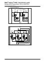
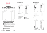
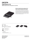
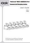
1
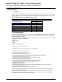
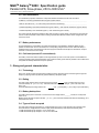
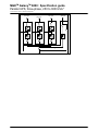
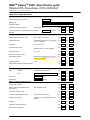
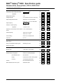
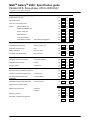
MGETM GalaxyTM 6000:
Specification guide
__________________________________
Parallel UPS, 250 to 3000 kVA*
* Power rating for an N+1 configuration.
MGETM GalaxyTM 6000 : Specification guide
Parallel UPS, three-phase, 250 to 3000 kVA*
* Power rating for an N+1 redundant configuration
Contents
1 - UPS definition .......................................................................................................................................... D-3
1.1 - Purpose ......................................................................................................................................... D-3
1.2 - Brief description ............................................................................................................................. D-3
2 - Operating principle.................................................................................................................................. D-4
2.1 - Normal operation ........................................................................................................................... D-4
2.2 - Operation on battery power ........................................................................................................... D-4
2.3 - Battery recharge ............................................................................................................................ D-4
2.4 - Parallel operation with redundancy ............................................................................................... D-4
2.4 - Transfer to bypass AC source....................................................................................................... D-4
2.5 - UPS maintenance.......................................................................................................................... D-4
2.6 - Battery maintenance...................................................................................................................... D-5
2.7 - Cold start (AC power absent) ........................................................................................................ D-5
3 - Sizing and general characteristics ........................................................................................................ D-5
3.1 - Technology .................................................................................................................................... D-5
3.2 - Rating ............................................................................................................................................ D-5
3.3 - Battery backup time....................................................................................................................... D-5
3.4 - Types of loads accepted................................................................................................................ D-5
3.5 - Limitation of harmonics upstream of the UPS............................................................................... D-6
3.6 - Efficiency ....................................................................................................................................... D-6
3.7 - Noise level ..................................................................................................................................... D-6
4 - AC sources............................................................................................................................................... D-6
4.1 - Normal AC source ......................................................................................................................... D-6
4.2 - Bypass AC source ......................................................................................................................... D-6
5 - Electrical characteristics ........................................................................................................................ D-6
5.1 - Rectifier and charger ..................................................................................................................... D-6
5.2 - Batteries......................................................................................................................................... D-7
5.3 - Inverter........................................................................................................................................... D-7
5.4 - Static bypass ................................................................................................................................. D-8
5.5 - Discrimination and short circuit capacity ....................................................................................... D-8
5.6 - System earthing arrangement ....................................................................................................... D-9
6 - Mechanical characteristics..................................................................................................................... D-9
6.1 - Mechanical structure ..................................................................................................................... D-9
6.2 - Modular design .............................................................................................................................. D-9
6.3 - Dimensions .................................................................................................................................... D-9
6.4 - Connections................................................................................................................................... D-9
6.5 - Ventilation ...................................................................................................................................... D-9
6.6 - Safety............................................................................................................................................. D-9
7 - Environment conditions ......................................................................................................................... D-10
7.1 - UPS (not including battery)............................................................................................................ D-10
8 - Protection ................................................................................................................................................. D-10
8.1 - UPS ............................................................................................................................................... D-10
8.2 - Rectifier/chargers .......................................................................................................................... D-10
8.3 - Inverters......................................................................................................................................... D-10
8.4 - Batteries......................................................................................................................................... D-10
9 - Battery management ............................................................................................................................... D-11
9.1 – Self-test......................................................................................................................................... D-11
9.2 - Measurement of actual backup time ............................................................................................. D-11
9.3 - Digital battery management........................................................................................................... D-11
9.4 - Block by block monitoring.............................................................................................................. D-11
10 - User interface and communication ..................................................................................................... D-12
10.1 - User interface .............................................................................................................................. D-12
10.2 - Communication............................................................................................................................ D-13
11 - Maintainability........................................................................................................................................ D-13
11.1 - Local and remote diagnostics and monitoring - E. Services ....................................................... D-13
12 - Standards and tests ............................................................................................................................. D-14
12.1 - Standards .................................................................................................................................... D-14
12.2 - Certification of conformity ............................................................................................................ D-14
13 - Test procedures and quality system .................................................................................................. D-14
13.1 - Test procedures........................................................................................................................... D-14
13.2 - Quality system ............................................................................................................................. D-14
14 - Services .................................................................................................................................................. D-15
14.1 - Maintenance ................................................................................................................................ D-15
14.2 - Technical competency................................................................................................................. D-15
14.3 - Functional components ............................................................................................................... D-15
14.4 - System start-up ........................................................................................................................... D-15
14.5 - Replacement parts ...................................................................................................................... D-15
14.6 - Recycling and renovation ............................................................................................................ D-15
15 - Warranty ................................................................................................................................................. D-15
16 - Installation services .............................................................................................................................. D-15
17 - Electrical diagram.................................................................................................................................. D-16
Appendix. Comparison table ....................................................................................................................... D-18
APC By Schneider Electric
Edition - 03/2009
Spec. E - 2
MGETM GalaxyTM 6000 : Specification guide
Parallel UPS, three-phase, 250 to 3000 kVA*
* Power rating for an N+1 redundant configuration
1 - UPS definition
1.1 - Purpose
The purpose of this specification is to define the design, manufacture and testing characteristics required in view of
supplying, putting into operation and maintaining an Uninterruptible Power Supply (referred to as a UPS in the rest
of this document).
The UPS shall be designed to supply dependable electric power to:
For information purposes
MTBF in
hours
475000
Single-UPS unit with static bypass
Active modular redundancy n+1 with centralized
bypass
2 UPS units
3 UPS units
4 UPS units
5 UPS units
6 UPS units
6
3.11x10
6
2.42x10
6
1.97 x10
6
1.67x10
6
1.44x10
Non availability
2.1x10
-5
-6
3.22x10
-6
4.14x10
-6
5.07 x10
-6
6 x10
-6
6.95 x10
1.2 - Brief description
The UPS system shall be made up of …[ 2 / 3 / 4 / 5 / 6 ]…identical parallel-connected UPS units with the same
power rating, operating in double-conversion mode (also called on-line mode) in accordance with the VFI category
described in standard IEC 62040-2.
Each UPS unit shall have a unit rating of …[ 250 / 300 / 400 / 450 500 / 600 / 800 ]… kVA, made up of the following
components, described in this specification:
ω rectifier;
ω battery charger;
ω inverter;
ω battery;
ω a battery-management system.
In addition, the UPS shall be equipped with:
…………………………………………………………………………………………………………………………..
() for parallel connection of two single UPS units, with redundancy)
ω static bypass (via a static switch) on each unit;
ω manual maintenance bypass on each unit;
ω user and communications interface on each unit.
…………………………………………………………………………………………………………………………..
() for parallel connection with an external maintenance-bypass cabinet, up to four units)
ω static bypass (via a static switch) on each unit;
ω common, external, maintenance bypass for all units, installed in a cabinet;
ω user and communications interface on each unit.
…………………………………………………………………………………………………………………………..
() for parallel connection with a centralized-bypass cabinet, up to six units)
ω a centralized bypass shall be made up of the following components:
- static bypass (via a static switch);
- manual maintenance bypass.
The centralized bypass shall be sized to support the entire load. Consequently, its power rating shall be
…[ 250 / 500 / 800 / 1200 / 2000 …] kVA.
ω a user and communications interface for the entire UPS system.
The UPS system shall also comprise any and all other devices required for safe operation and maintenance,
including circuit breakers, switches, etc.
The UPS system shall ensure continuity of electric power to the load within the specified tolerances, without
interruption upon failure or deterioration of the normal AC source (utility power) for a maximum protection time
determined by the capacity of the backup batteries installed.
APC By Schneider Electric
Edition - 03/2009
Spec. E - 3
MGETM GalaxyTM 6000 : Specification guide
Parallel UPS, three-phase, 250 to 3000 kVA*
* Power rating for an N+1 redundant configuration
2 - Operating principle
The double-conversion UPS (also called on-line) shall operate as defined below.
2.1 - Normal operation
(normal AC source available)
The rectifier supplies the inverter with DC current while the charger simultaneously float charges the battery. The
load is continuously supplied with dependable electrical power by the inverter.
() for parallel connection with a centralized bypass cabinet, up to six units)
A current-loop system shall ensure automatic distribution of the total load between the various parallel-connected
units.
2.2 - Operation on battery power
(normal AC source not available or outside tolerances)
Upon failure or excessive deterioration of the normal AC source, the inverter shall continue to supply the load from
battery power without interruption or disturbance, within the limits imposed by the specified battery backup time.
2.3 - Battery recharge
(normal AC source restored)
When the normal AC source is restored, the rectifier shall again power the inverter, without interruption or
disturbance to the load, while the charger automatically recharges the battery.
2.4 - Parallel operation with redundancy
………………………………………………………………………………………………………………………………….
() without redundancy)
The system shall not be redundant. The [ 2 / 3 / 4 ] UPS units must operate in parallel to supply the load. Shutdown
of one unit shall result in transfer to
…[ the various static bypasses, connected to the same bypass AC source ]
…[ the centralized bypass ]
…………………………………………………………………………………………………………………………………..
() with redundancy)
The units shall operate in parallel and redundantly, with the load shared equally between the units.
Redundancy shall be of the "n+1" (or n+2) type, i.e. "1" (or 2) units shall be redundant in the total of n units. If a
major fault occurs on a unit, it shall automatically disconnect.
If the remaining unit(s) are sufficient to supply the load, it/they shall remain in operation.
If the total available power is insufficient, the load shall be automatically transferred, without interruption, to the
bypass AC source, if it is within tolerances.
…………………………………………………………………………………………………………………………………..
2.5 - Transfer to bypass AC source
In the event of an overload exceeding system capabilities or UPS shutdown, the static bypass switch shall
instantaneously transfer the load to the bypass AC source without interruption, on the condition that bypass power
is available and within tolerances.
…………………………………………………………………………………………………………………………………..
() for parallel connection with an external maintenance-bypass cabinet, up to four units)
During transfer, the system shall simultaneously switch the static switches.
…………………………………………………………………………………………………………………………………..
() for parallel connection with a centralized-bypass cabinet, up to six units)
Transfer shall be carried out by the common static bypass in the centralized-bypass cabinet, with simultaneous
orders to the UPS units.
………………………………………………………………………………………………………………………………….
Transfer of the load back to the UPS-unit output, synchronised with the bypass AC source, shall be automatic or
manual. During transfer, the load shall not suffer an outage or disturbance in the supply of power.
On request, the UPS system may automatically transfer the load with a micro-interruption if a major fault occurs on
the UPS system and if synchronisation with the bypass source has not been established.
APC By Schneider Electric
Edition - 03/2009
Spec. E - 4
MGETM GalaxyTM 6000 : Specification guide
Parallel UPS, three-phase, 250 to 3000 kVA*
* Power rating for an N+1 redundant configuration
2.6 - UPS maintenance
For maintenance purposes, all electronic components shall be accessible from the front of the UPS.
In addition, a manually operated mechanical bypass system shall be:
…………………………………………………………………………………………………………………………………..
- Built into each UPS unit () for a two-UPS system with active redundancy)
…………………………………………………………………………………………………………………………………..
- Installed separately in the external maintenance bypass cabinet () with external maintenance-bypass cabinet)
…………………………………………………………………………………………………………………………………..
- Installed separately in the centralized bypass () with centralized-bypass cabinet).
This system shall be designed to isolate the UPS while continuing to supply power to the load from the bypass AC
source. The UPS shall also include a device making it possible to isolate the rectifiers and the chargers from the
normal AC source.
2.7 - Battery maintenance
For safe maintenance on the battery, the system shall include a circuit breaker to isolate the battery of each
parallel-connected UPS unit from the rectifier, the corresponding charger and the inverter. When the battery is
isolated from the system, the UPS shall continue to supply the load without interruption or disturbance, except in
the event of a normal AC source outage.
2.8 - Cold start (normal AC source absent)
The battery of each unit shall be capable of ensuring UPS start-up even if normal AC power is not available and
continuing operation within the specified back-up time (start on battery power shall be possible on the condition that
the system was already started with AC power present).
3 - Sizing and general characteristics
3.1 - Technology
Each unit in the UPS system shall be based on IGBT technology with built-in thermal monitoring and a high freefrequency chopping mode to dynamically optimise efficiency and power quality.
3.2 - Rating
The UPS system shall be sized to continuously supply a load of
kVA, at a power factor (pf) of 0.8.
It shall be made up of ...[2 / 3 / 4 / 5 / 6]... UPS units, each with an identical rating of ...[ 250 / 300 / 400 / 500 /
600]... kVA.
The total installed power rating shall thus be
kVA. ...[Consequently, 1 (or 2) unit(s) may be redundant.]
3.3 - Battery backup time
The battery backup time in the event of a normal AC source outage shall be _______ minutes, for a load power
factor of 0.8.
Battery service life shall be equal to at least …[ 5 / 10 ]…years. It shall be selected and sized correspondingly, for a
load power factor of 0.8.
3.4 - Types of loads accepted
The UPS shall accept high crest factors (3:1) without derating to ensure correct operation with computer loads.
The total harmonic voltage distortion at UPS output (THDU downstream) shall respect the following limits:
ω THDU downstream ph/ph and ph/N ≤ 4% for linear loads;
ω THDU downstream ph/ph and ph/N ≤ 4 % for non-linear loads.
APC By Schneider Electric
Edition - 03/2009
Spec. E - 5
MGETM GalaxyTM 6000 : Specification guide
Parallel UPS, three-phase, 250 to 3000 kVA*
* Power rating for an N+1 redundant configuration
3.5 - Limitation of harmonics upstream of the UPS
The UPS system shall not draw a level of harmonic currents that could disturb the upstream AC system, i.e. it shall
comply with the stipulations of guide IEC 61000-3-4.
To that end, it shall be possible to equip each rectifier/charger input with a filter of the type …[compensated LC /
non-compensated LC / with contactor / double-bridge / phase shifting]...
If necessary, it shall be possible to use an electronic active filtering system to obtain, at the normal AC input, the
following levels, constant from 50% to 100% load:
ω total harmonic current distortion (THDI) upstream of the rectifier/charger not exceeding 4%;
ω input power factor (pf) greater than 0.94.
3.6 - Efficiency
Overall efficiency shall be greater than or equal to:
ω 95% at full rated load (In);
ω 93% at half rated load (In/2).
3.7 - Noise level
The noise level for each unit, measured as per standard ISO 3746, shall be less than:
.........................................................................................................................................................................
ω 69 dBA () for 250 and 300 kVA units).
ω 72 dBA () for 400, 450, 500 and 600 kVA units).
.........................................................................................................................................................................
4 - AC sources
The UPS shall be designed to receive power from the sources listed below.
4.1 - Normal AC source
(rectifier input)
The normal AC source supplying the UPS shall, under normal operating conditions, have the following
characteristics:
ω rated voltage: 380 - 400 or 415 volts rms at full rated load Pn;
ω voltage:
volts, ± 15%;
ω number of phases: 3 + N + earth;
ω frequency:
Hz ± 10%.
4.2 - Bypass AC source
(static-bypass input, if separate from rectifier input)
The bypass power supplying the UPS in the event of an inverter shutdown (maintenance, failure) or an overload
(short-circuit, heavy inrush currents, etc.) shall have the following characteristics:
ω voltage:
/
volts, ± 10%;
ω number of phases: 3 + N + earth; (a non-distributed neutral is possible);
Hz ± 5% (adjustable up to ± 2 Hz).
ω frequency:
Outside these tolerances, it shall be possible to supply the load, but in downgraded mode.
5 - Electrical characteristics
5.1 - Rectifier and charger
5.1.1 - Supply
The rectifier and charger module shall be supplied via the normal AC input (see § 4. AC sources) and shall have
the characteristics presented below.
5.1.2 - Inrush current
A device shall be provided to limit inrush currents.
When AC power fails and during genset start, the rectifier shall limit the power drawn to 70% of its rating for ten
seconds. The remaining 30% shall be supplied by the battery.
5.1.3 - Battery-current limiting
For long battery life, an electronic device shall automatically limit the charging current to the maximum value
APC By Schneider Electric
Edition - 03/2009
Spec. E - 6
MGETM GalaxyTM 6000 : Specification guide
Parallel UPS, three-phase, 250 to 3000 kVA*
* Power rating for an N+1 redundant configuration
specified by the battery supplier (0.1 x C10 for a sealed lead-acid battery).
5.1.4 - Operating mode
The charger of each UPS unit shall be sized to recharge the battery rapidly:
a battery with a backup time of…[5 / 10 minutes in less than 11 hours] [15 minutes in less than 13 hours] (following
a discharge to Pn/2 to recover 90% of backup time).
5.1.6 - Input power factor
The required level of performance is indicated in section 3.5 "Limitation of harmonics upstream of the UPS".
5.1.7 - Voltage regulation
Rectifier/charger regulation shall take into account the ambient temperature of the battery and shall ensure DC
output voltage fluctuations of less than 1% irrespective of load and AC input voltage variations (within the limits
specified in section 4.1 “Normal AC source”).
5.2 - Batteries
Each UPS unit shall be equipped with its own battery of the …[sealed lead-acid type, factory mounted and wired in
a cabinet identical to that of the UPS,] … [sealed lead-acid type, mounted on shelves,]…[vented lead-acid type,
mounted on a rack,]... with a service life equal to at least …[5 / 10]… years.
Each battery shall be sized to ensure continuity in the supply of power to the corresponding inverter for at least
…[8 / 10 / 15 / 30 / 60…]… minutes, in the event of a normal AC source failure, with the inverter operating at full
kVA at a power factor (pf) of 0.8.
rated load, i.e.
Sizing calculations shall assume an ambient temperature between 0° C and 35° C
The UPS shall include devices to ensure:
ω effective battery protection (see section 8.4 "Protection - Battery");
ω battery management (see section 9 "Battery management").
5.3 - Inverter
Each inverter shall be sized to supply a rated load of …[ 250 / 300 / 400 / 450 / 500 / 600 ]… kVA at 0.8 pf and
shall satisfy the specifications listed below.
5.3.1 - Output voltage
ω Rated voltage
…[ 380 / 400 / 415 ]… volts rms, adjustable via the user interface (see section 10), within tolerances of +/- 3%.
ω Number of phases
3 phases + neutral + earth.
ω Steady-state conditions
The variation in the rated voltage shall be limited to ± 2% for a balanced load between 0 and 100% of the rated
power, irrespective of normal AC input and DC voltage levels, within the limits specified in section 4.1 “Normal AC
source” and 5.1.4 “Rectifier/charger - Operating modes and DC-voltage levels”.
ω Voltage variations for load step changes
Output voltage transients shall not exceed ± 1% of rated voltage for 0 to 100% or 100 to 0% step loads. In all
cases, the voltage shall return to within steady-state tolerances in less than 100 milliseconds.
ω Unbalanced load conditions
For a load unbalance greater than 30%, the voltage unbalance shall be less than 2% for the phase-to-neutral
amplitude and 3 degrees for the phase angle deviation.
5.3.2 - Output frequency
ω Rated frequency
- 50 or 60 Hz.
ω Variations in free-running frequency mode:
- ± 0.5 Hz.
APC By Schneider Electric
Edition - 03/2009
Spec. E - 7
MGETM GalaxyTM 6000 : Specification guide
Parallel UPS, three-phase, 250 to 3000 kVA*
* Power rating for an N+1 redundant configuration
5.3.3 - Synchronisation with bypass power
ω When bypass power is within tolerances
To enable transfer to bypass power (see conditions below in section 5.4 "Static-bypass"), the inverter output
voltage shall be synchronised with the bypass source voltage whenever possible. To that end, during normal
operation, a synchronisation system shall automatically limit the phase deviation between the voltages to 3
degrees, if the bypass source frequency is sufficiently stable (within adjustable tolerances of ± 0.5 Hz with respect
to the rated frequency).
ω Synchronisation with an external source
It shall be possible to synchronise with all types of external source.
For example, if the bypass source is a generator set, the synchronization tolerances shall be approximately
± 2 Hz (adjustable).
ω Autonomous operation following loss of synchronisation with bypass power
When the bypass source frequency deviates beyond these limits, the inverter shall switch over to free-running
mode with internal synchronisation, regulating its own frequency to within ± 0.1 %. When bypass power returns to
within tolerances, the inverter shall automatically resynchronise.
ω Variation in frequency per unit time
To avoid transmitting to the inverter any excessive frequency variations on the bypass AC source when it is within
tolerances, inverter frequency variations per unit time (dF/dt) shall be limited to 1 Hz/s or 2 Hz/s (user defined).
5.3.4 - Overload capacity
The UPS shall be capable of supplying for at least:
ω 1 minutes a load representing 165% of the rated load;
ω 1 second a load representing 200% of the rated load.
If necessary, the UPS shall operate as a generator (current limiting) with a peak capacity of 233% for 150
milliseconds, to allow highly disturbed transient operating states (high overloads, very high crest factors, etc.)
without transferring the load to the bypass.
5.4 - Static bypass
5.4.1 - Load transfer to the static bypass
Instantaneous transfer of the load from the inverters to bypass power and back shall take place without a break or
disturbance in the supply of power to the load, on the condition that the bypass source voltage and frequency are
within the tolerances specified in section 4.1 "Bypass AC source" and that the inverters are synchronized. Transfer
shall take place automatically in the event of a major overload or an internal UPS-system fault. Manually initiated
transfer shall also be possible.
If the bypass power is outside the specified tolerances or is not synchronized with the inverters, automatic transfer
of the load from the inverters to bypass power shall be inhibited or shall take place after a calibrated interruption of
500 to 800 milliseconds.
Manual initiation of this transfer as well as transfer back to the inverters shall also be possible.
5.4.2 - Static-switch protection
The static switch
.........................................................................................................................................................................
[ common centralized-bypass ] () with centralized-bypass cabinet)
.........................................................................................................................................................................
[ in each UPS unit ] (other cases)
.........................................................................................................................................................................
shall be equipped with an RC filter for protection against switching overvoltages and lightning strikes.
5.5 - Discrimination and short-circuit capacity
If the bypass power is within the tolerances specified in section 4.2 "Bypass AC source" section, the presence of
the static switch
.........................................................................................................................................................................
[ common centralized-bypass ] () with centralized-bypass cabinet)
.........................................................................................................................................................................
[ in each UPS unit, supplied by the same bypass AC source ] (other cases)
.........................................................................................................................................................................
shall make it possible to use the short-circuit power of the bypass source to trip the downstream protection devices
of the inverter.
To ensure tripping in a selective manner, the available power shall be sufficient to trip protection devices with high
ratings (circuit breaker rated In/2 or UR fuses rated In/4, where In is the rated inverter current).
If the bypass source is outside the specified tolerances, the inverter on its own shall, for the same discrimination
requirements, be capable of tripping circuit breakers rated In/2 or UR fuses rated In/4, irrespective of the type of
short-circuit.
APC By Schneider Electric
Edition - 03/2009
Spec. E - 8
MGETM GalaxyTM 6000 : Specification guide
Parallel UPS, three-phase, 250 to 3000 kVA*
* Power rating for an N+1 redundant configuration
5.6 - System earthing arrangement
The UPS shall be compatible with the following system earthing arrangements:
ω upstream source
…[ TT/ IT / TNS / TNC ]…
ω downstream installation
…[ TT/ IT / TNS / TNC ]…
If the upstream and downstream earthing arrangements are different, galvanic isolation shall be provided on the
static-bypass line.
6 - Mechanical characteristics
6.1 - Mechanical structure
UPSs and batteries shall be installed in cabinet(s) with a degree of protection IP20 (standard IEC 60529). Access
to the subassemblies making up the system shall be exclusively through the front.
…………………………………………………………………………………………
6.2 - Modular design
The UPS system shall be designed to allow the installed power to be easily increased on site by connection of
additional UPS units, either to meet new load requirements or to enhance system availability by introducing
redundancy.
This transformation shall be possible directly on site, without returning the equipment to the factory and without
causing excessive system downtime.
6.3 – Dimensions
The UPS shall require as little floor space as possible. To gain space, it shall be possible to install the UPS with the
back to the wall.
6.4 - Connection
To facilitate connections, all terminal blocks must be easily accessible from the front when the UPS is installed with
the back to the wall. Entry of upstream and downstream power cables, as well as any auxiliary cables, shall be
possible through the bottom for a false floor.
The UPS shall be equipped with an earth-circuit connector, in compliance with the standards listed in section 13
"Standards and tests".
The cables shall comply with the standards listed in section 12 "Standards and tests" and be mounted in
compliance with the stipulations in section 6.6 "Safety". The neutral conductor shall be oversized for any third-order
harmonic currents and their multiples (the size of the neutral shall be 1.5 times that of each phase).
6.5 - Ventilation
The UPS units shall be provided with forced-air cooling.
To facilitate positioning of UPS units (back to the wall), ventilation shall take place through the top with an air intake
on the front.
6.6 - Safety
For the safety of maintenance personnel, the cabinet shall be provided with a manually operated mechanical
bypass designed to isolate the rectifier, charger, inverter and static switch while continuing to supply the load from
the bypass AC source.
It shall be possible to send to the UPS an external EPO order resulting in opening of the battery circuit breaker and
the upstream circuit breaker.
APC By Schneider Electric
Edition - 03/2009
Spec. E - 9
MGETM GalaxyTM 6000 : Specification guide
Parallel UPS, three-phase, 250 to 3000 kVA*
* Power rating for an N+1 redundant configuration
7 - Environment conditions
7.1 - UPS (not including battery)
7.1.1 - Operation
The UPS, not including the battery, shall be capable of operating under the following environmental conditions
without loss of performance:
ω ambient temperature range: 0° C to +40° C.
ω recommended temperature range: +20° C to + 25° C;
ω maximum temperatures: 40 °C for 8 hours
ω maximum relative humidity: 95% at 25° C;
ω maximum altitude: 1000 meters.
7.1.2 - Storage
The UPS, not including the battery, shall be designed for storage under the following conditions:
ω ambient temperature range: -10° C to +45° C.
8 - Protection
8.1 - UPS
Each UPS unit shall include protection against AC-source overvoltages (as per standard IEC 60146), excessive
external or internal temperature rise and vibrations and impacts during transport.
8.2 - Rectifier and charger
Each rectifier/charger shall be equipped to receive an external order to automatically shut down under the following
circumstances:
ω emergency off; in this case, the shutdown will be accompanied by opening of the battery circuit breaker;
ω battery room ventilation fault.
The rectifier and the charger shall automatically shut down if the DC voltage reaches the maximum value specified
by the battery manufacturer.
8.3 - Inverter
The load shall be protected against any overvoltages that could result from voltage regulation failure at the output
of the inverters.
The inverter (and the corresponding rectifier/charger) shall automatically shut down if the DC voltage reaches the
minimum value specified by the battery manufacturer.
Each inverter shall be equipped with an automatic shutdown system to protect its power circuits against overloads
exceeding UPS-system overload capacity when bypass power is not available. In particular, a short-circuit on the
load shall initiate a static shutdown of each inverter, without blowing a fuse.
8.4 - Batteries
8.4.1 - Protection against deep discharge and self-discharge
The UPS shall comprise a device designed to protect the battery against deep discharges, taking into account the
characteristics of the discharge cycles, with isolation of the battery by a circuit breaker.
8.4.2 - Independent regulation and monitoring systems
A regulation system shall regulate the battery voltage and the charge current.
A second system, independent of the regulation, shall monitor the battery voltage and the charge current.
Consequently, if the regulation system fails, the monitoring system steps in to shut down the charger and avoid
overcharging.
8.4.3 - Regulation of the battery voltage depending on the ambient temperature
A temperature sensor adapts the charge voltage to the ambient temperature.
This regulation system takes into account the chemical reaction and prolongs the battery service life.
The permissible temperature range is set in the personalisation parameters.
An alarm shall be issued for temperatures outside the permissible range.
8.4.4 - Self-test
Battery monitoring shall be carried out by an automatic device. Self-test intervals shall be set to one month by
default, but shall be adjustable.
This self-test system shall, where necessary, initiate indications via LEDs on the front panel or a message to a
remote monitoring system.
APC By Schneider Electric
Edition - 03/2009
Spec. E - 10
MGETM GalaxyTM 6000 : Specification guide
Parallel UPS, three-phase, 250 to 3000 kVA*
* Power rating for an N+1 redundant configuration
9 - Battery management
As the life of the batteries is very sensitive to operating conditions, the battery shall be managed in an optimum
manner.
In addition to the devices indicated in section 8.4 "Batteries", the battery-management system shall include the
features listed below.
9.1 - Self-test
The battery shall include a self-test system initiated in two manners:
ω as necessary by a manual command;
ω automatically at user-defined intervals.
This self-test system shall update the battery parameters and detect any abnormal deterioration to facilitate
preventive maintenance.
9.2 - Measurement of actual backup time
The battery function shall be combined with a system that continuously monitors the actual backup time available
(AC source present) or remaining (AC source absent), according to the actual load on the UPS, the battery
temperature and the age of the battery.
9.3 - Digital battery monitoring
Each UPS shall be equipped with a system for battery digital management.
Based on a number of parameters (percent load, temperature, battery type and age), the system shall control the
battery charge voltage and continuously calculate:
ω The true available backup time
ω The remaining service life.
9.4 - Block by block monitoring
To further optimise battery availability and service life, it shall be possible to equip each UPS with an optional
system to continuously monitor all battery strings and display a block by block failure prediction.
The system shall include the functions listed below.
ω Continuous measurement of the voltage of each block.
ω Continuous measurement of the internal resistance.
ω Identification of faulty blocks (trend curves).
ω Possibility of replacing individual blocks.
ω Remoting of all information via Ethernet, dry contacts or JBus.
APC By Schneider Electric
Edition - 03/2009
Spec. E - 11
MGETM GalaxyTM 6000 : Specification guide
Parallel UPS, three-phase, 250 to 3000 kVA*
* Power rating for an N+1 redundant configuration
10 - User interface and communication
10.1 - User interface
UPS operation shall be facilitated by a user interface comprising:
ω a graphic display (at least quarter VGA and high resolution are preferable);
ω controls;
ω status indications with mimic panel.
10.1.1 - Graphic display
The graphic display shall facilitate operation by offering the functions listed below.
ω operating language
language all the operating information supplied on the
It shall be possible to display in the
screens.
ω step by step operating help
The graphic display shall assist the user by providing step by step help in the user's language.
ω animated colour mimic diagram
The mimic diagram shall enable display of installation parameters, configuration, operating status and alarms and
indication of operator instructions for switching operations (e.g. bypass).
ω display of measurements
It shall be possible to display the following measurements:
- inverter output phase-to-phase voltages;
- inverter output currents;
- inverter output frequency;
- voltage across battery terminals;
- battery charge or discharge current;
- rectifier/charger input phase-to-phase voltages;
- rectifier/charger input currents;
- crest factor;
- active and apparent power;
- power factor of the load;
- battery temperature.
ω display of status conditions and events
It shall be possible to display the following indications:
- load on battery power;
- load on UPS;
- load on automatic bypass;
- general alarm;
- battery fault;
- remaining battery backup time;
- low battery warning;
- bypass AC source outside tolerances;
- battery temperature.
Additional information shall be provided in view of accelerating servicing of the system, as specified in section 11
“Maintainability”.
ω display of operating graphs
It shall be possible to display on the screen curves and bargraphs over significant periods for the measurements
mentioned above.
ω log of time-stamped events
This function shall store in memory and make available, for automatic or manually initiated recall, time-stamped
logs of all important status changes, faults and malfunctions, complete with an analysis and display of
troubleshooting procedures. It shall be possible to time stamp and store at least 3 000 events.
10.1.2 - Controls
The UPS shall comprise the following controls:
ω two ON and OFF buttons
Located on the front panel of the UPS, they shall control UPS-unit ON/OFF status.
It shall be possible to turn OFF the UPS externally via an isolated dry contact.
ω EPO terminal block
The UPS shall be equipped with an emergency power off terminal block for complete system shutdown following
reception of an external control signal. The EPO command shall result in:
- shutdown of UPS units;
- opening of the static switch on the bypass line and of the battery circuit breaker;
- opening of an isolated dry contact on the programmable card.
ω alarm reset button
This button shall turn off audio alarms (buzzer) (see section 10.1.3). If a new alarm is detected after clearing the
first, the buzzer sounds again.
APC By Schneider Electric
Edition - 03/2009
Spec. E - 12
MGETM GalaxyTM 6000 : Specification guide
Parallel UPS, three-phase, 250 to 3000 kVA*
* Power rating for an N+1 redundant configuration
10.1.3 - Status indications with mimic panel
Indication of status conditions shall be distinct of the graphic display.
Three LEDs on the control panel indicate the following status conditions:
ω load protected;
ω minor fault;
ω major fault.
The mimic panel shall represent the UPS and indicate the status of the load supply using five two-colour (red and
green) LEDs:
ω load supplied (LED at UPS output on mimic panel),
ω inverter on (inverter LED on mimic panel),
ω operation on battery power (LED between battery and inverter on mimic panel),
ω bypass activated (bypass LED on mimic panel),
ω PFC rectifier on (rectifier LED on mimic panel).
A buzzer shall warn the user of faults, malfunctions or operation on battery power.
10.2 - Communication
10.2.1 - Standard communication
It shall be possible to remote the following controls, indications and measurements. To that end, the UPS shall
have as standard equipment:
ω a programmable communication card for data input/output.
The card shall be equipped with eight dry contacts, six for input data and two for output data.
ω at least three communication ports for later addition, without interrupting operation, of communication cards
implementing different protocols, e.g. SNMP, JBus/ModBus, RS232, USB.
10.2.2 - Communications options
The UPS shall be designed to enable the extension of communications, without system shutdown, to the following
types of cards:
ω an SNMP communication card for connection to an Ethernet network, for connection to a computer-network
management system;
ω an RS485 serial-link communication card capable of implementing the JBus/ModBus protocol for connection to a
building management system (BMS);
ω an RS232 serial-link communication card for communication with a modem and a remote-maintenance system;
ω an USB communication card;
ω an XML-Web communication card for direct UPS connection to an intranet network, without connection to a
server, capable of supplying information via a standard web browser.
The UPS shall be detectable by supervision software for large UPS systems.
Shutdown and administration software shall be available in addition to the communication cards.
11 - Maintainability
For optimum safety during servicing, a maintenance bypass shall be available to completely isolate the UPS.
11.1 - Local and remote diagnostics and monitoring - E. Services
ω The UPS shall be equipped with a self-test system to check operation of the system as a whole each time it is
started. To that end, the supply control/monitoring electronics shall offer:
ω auto-compensation of component drift;
ω acquisition of information vital for computer-aided diagnostics or monitoring (local or remote);
ω overall readiness for remote supervision services provided by the manufacturer.
APC By Schneider Electric
Edition - 03/2009
Spec. E - 13
MGETM GalaxyTM 6000 : Specification guide
Parallel UPS, three-phase, 250 to 3000 kVA*
* Power rating for an N+1 redundant configuration
12 - Standards and tests
12.1 - Standards
All equipment shall be designed and built in accordance with accepted engineering practice and applicable
international standards, in particular the standards listed below.
ω IEC 6014A-4: UPS - Performance.
ω IEC 62040-1 and EN 62040-1: UPS - Safety.
ω IEC 62040-2 and EN 62040-2: UPS - Electromagnetic compatibility - [level C3 / C2 class A is optional].
ω IEC 62040-3 and EN 62040-3: UPS - Performance.
ω IEC 60950 / EN 60950: Safety of IT equipment, including electrical business equipment.
ω IEC 61000-2-2: Compatibility levels for low-frequency conducted disturbances and signalling in public lowvoltage power supply systems.
ω IEC 61000-4: EMC - Electrical fast transient/burst immunity.
ω IEC 439: Low-voltage switchgear and controlgear assemblies.
ω IEC 60529: Degrees of protection provided by enclosures (IP Code).
ω ISO 3746: Sound power levels.
ω CE marking.
What is more, the equipment must comply with environmental-protection standards, with production taking place on
premises certified ISO 14001. The UPS design procedure shall be covered by an ISO 9001 quality system as well
as a dependability study to ensure maximum reliability.
12.2 - Certification of conformity
The manufacturer shall provide, on request, a complete qualification file demonstrating compliance with the above
standards. What is more, the indicated levels of performance shall be confirmed by certification from independent
laboratories (e.g. TÜV or Veritas).
13 - Test procedures and quality system
13.1 - Test procedures
The UPS manufacturer shall provide proof of a stringent Quality Assurance programme.
In particular, the main equipment manufacturing stages shall be sanctioned by appropriate tests such as:
ω incoming components inspection, discrete subassembly testing;
ω complete functional checks on the final product.
Equipment shall undergo on-load burn-in before leaving the factory.
Final inspection and adjustments shall be documented in a report drawn up by the supplier’s Quality Inspection
department.
ISO 9001 or 9002 certification of the production site is compulsory.
13.2 - Quality system
The UPS design procedure shall be covered by an ISO 9001 quality system as well as a dependability study to
ensure maximum reliability.
APC By Schneider Electric
Edition - 03/2009
Spec. E - 14
MGETM GalaxyTM 6000 : Specification guide
Parallel UPS, three-phase, 250 to 3000 kVA*
* Power rating for an N+1 redundant configuration
14 - Services
14.1 - Maintenance
The supplier shall propose contracts covering four levels of maintenance.
ω Level one: simple checks and settings, procedures accessible without any dismounting and involving no risk.
ω Level two: preventive maintenance, checks not inhibiting continuous operation of the system and preparing
operators for Manufacturer services.
ω Level three: trouble-shooting. Repairs by standard exchange of subassemblies and functional power and control
components. Preventive-maintenance operations, both systematic and when indicated by qualified diagnosis.
ω Level four: major preventive and corrective maintenance operations or technical upgrades during start-up,
operation or renovation of the UPS installation and recycling of equipment or components representing a risk.
These operations require the use of devices and means that have been calibrated by certified organisations.
14.2 - Technical competency
ω customer operators: the supplier shall offer a level 2 training program.
ω service personnel: the supplier shall ensure that service personnel are qualified for level 4.
14.3 - Functional components - organisation of supplier services
ω Sufficient geographical proximity of the supplier or an authorised agent shall ensure reasonable access times to
the customer site in view of reducing the mean time to repair (MTTR). The supplier shall be in a position to offer a
contract limiting the response time to four hours.
ω The supplier's logistics system and the availability 24 hours a day of original replacement parts shall similarly
contribute to reducing to the greatest extent possible the mean time to repair (MTTR).
14.4 - System start-up
ω The system and equipment shall be started up on site by the supplier or its authorised agent. The procedure
shall include checks on the characteristics of the upstream and downstream protection devices and on the UPS
installation parameters.
14.5 - Replacement parts
ω The suppler shall undertake to provide certified original replacement parts for at least ten years following the date
of delivery.
14.6 Recycling and renovation/substitution
ω At the end of the UPS service life, the supplier shall guarantee the continuity of service of the customer's
installations if necessary, including dismantling of equipment and replacement of equipment, in compliance with
applicable standards on environmental protection.
15 - Warranty
The rectifier/charger and inverter subassemblies shall be guaranteed (parts and labour on site) for one year
following the start-up date.
The sealed lead-acid battery shall be covered by the same warranty as the UPS.
16 - Installation services
Required services include:
ω supply of the UPS and any accessory parts or elements;
ω carriage-paid UPS transportation and delivery to the site.
Options:
ω UPS handling and installation on the site;
ω connections between the battery and the UPS;
ω connection of the normal AC source to the rectifier/charger;
ω connection of the bypass AC source to the input transformer or bypass input;
ω connection of the load circuits to the UPS output.
APC By Schneider Electric
Edition - 03/2009
Spec. E - 15
MGETM GalaxyTM 6000 : Specification guide
Parallel UPS, three-phase, 250 to 3000 kVA*
* Power rating for an N+1 redundant configuration
17 - Electrical diagram
Bypass AC input
Normal
AC input
Normal
AC input
Battery
Battery
UPS 1
UPS 2
P1 (kVA)
P1 (kVA)
Load
P < P1
Fig. 1. Two parallel-connected UPS units, with or without redundancy.
Bypass
AC input
External bypass cabinet
Normal
AC input
UPS1
P1 (kVA)
Normal
AC input
Normal
AC input
UPS2
P1 (kVA)
UPS3
P1 (kVA)
Load
Fig. 2. UPS system with common, external bypass (up to four units).
APC By Schneider Electric
Edition - 03/2009
Spec. E - 16
MGETM GalaxyTM 6000 : Specification guide
Parallel UPS, three-phase, 250 to 3000 kVA*
* Power rating for an N+1 redundant configuration
Normal
AC input
Normal
AC input
Normal
AC input
Bypass
AC input
Centralized bypass
Load
Fig. 3. UPS system with centralized bypass (up to six units).
APC By Schneider Electric
Edition - 03/2009
Spec. E - 17
MGETM GalaxyTM 6000 : Specification guide
Parallel UPS, three-phase, 250 to 3000 kVA*
* Power rating for an N+1 redundant configuration
Appendix. Comparison table
Type of UPS
Total rated power (kVA) at PF 0.8
kVA
Manufacturer
Range of products
Operating mode (IEC 62040-2)
double conversion
Parallel connection ≤ 4 modules without interrupting
operation
kVA max.
yes
no
yes
no
Rectifiers
Three-phase input voltage at Pn
380 or 400 or 415 V ± 15 %
yes
no
Rated active power
constant for loads with cos ϕ 0.8 lagging
to cos ϕ 0.9 leading
yes
no
Frequency
50 or 60 Hz ± 10 %
yes
no
Sinusoidal input current
THDI upstream ≤ 4 % with THM filter
yes
no
Input power factor
PF > 0.94
yes
no
yes
no
No inrush or start-up current
Rapid battery charger
Backup time 10 minutes in t ≤ 11 hours,
4 hours in t ≤ 24 hours
yes
no
Voltage regulation
±1%
yes
no
yes
no
yes
no
yes
no
Independent regulation/monitoring systems
Battery
Type
standard
sealed lead acid in a cabinet
other
Service life
years
yes
no
Backup time
minutes
yes
no
yes
no
yes
no
yes
no
Battery management and protection
Temperature correction
Measurement of actual backup time,
depending on:
load, temperature, age
Cold start on battery power
Protection against deep discharge
with circuit-breaker opening
yes
no
Charge-current limiting
0.05 C10 to 0.1 C10 (depending on the
battery)
yes
no
Self-tests
yes
no
Calculation of real backup time
yes
no
Block by block monitoring
yes
no
APC By Schneider Electric
Edition - 03/2009
Spec. E - 18
MGETM GalaxyTM 6000 : Specification guide
Parallel UPS, three-phase, 250 to 3000 kVA*
* Power rating for an N+1 redundant configuration
Inverter
Volts
yes
no
±3%
yes
no
Steady-state conditions
± 1%
yes
no
Voltage transients
± 3% (load from 0 to 100 or 100 to 0 %)
yes
no
Output voltage distortion at Pn
THDU ph-N < 4% for linear loads
yes
no
THDU ph-N < 4% for non-linear loads
yes
no
yes
no
± 0.5 Hz
yes
no
± 0.25 Hz to 2 Hz
yes
non
Frequency synchronisation with an external ± 8 % of rated frequency
source
yes
no
Overload capacity
125% In for 10 minutes
yes
no
165% In for 1 minute
yes
no
Current limiting
233% In for 150 milliseconds
yes
no
Crest factor
up to 3:1
yes
no
yes
no
yes
no
yes
no
> 95% at Pn, > 92 % at Pn/2
yes
no
selection of operating language
yes
no
personalisation menu
with password
yes
no
display
measurements, status, events, graphs
yes
no
event log
Time-stamping 2000 events
yes
no
Controls
ON, OFF, EPO terminal block
yes
no
Status indications with mimic panel
Audio alarm, LEDs
yes
no
Three-phase output voltage with neutral
adjustable
Hz
Output frequency
Variation in output frequency
adjustable
Static bypass
Static bypass
Short-circuit withstand of static bypass
depending on power
Maintenance bypass
Efficiency
Normal mode
User interface
Graphic display 15 languages
APC By Schneider Electric
Edition - 03/2009
Spec. E - 19
MGETM GalaxyTM 6000 : Specification guide
Parallel UPS, three-phase, 250 to 3000 kVA*
* Power rating for an N+1 redundant configuration
Communication
Programmable relay card
yes
no
EPO terminal block
yes
no
3 slots for communication cards
yes
no
Options
Ethernet SNMP card
yes
no
RS485 JBus/ModBus card
yes
no
RS232 U-Talk card
yes
no
XML-Web card
yes
no
Supervision software
yes
no
with shutdown management
yes
no
Certified standards and tests
See list in section 12.1
yes
no
Certification of performance
TÜV
yes
no
Quality certification
ISO 9001 / 9002
yes
no
Eco-design and manufacturing
ISO 14001 site
yes
no
Technical competency of supplier
Level 4 NFX 060-010
yes
no
Diagnostics and monitoring
Remote
yes
no
Technical support
International
yes
no
yes
no
Administration software
Certification
Services
Operation, Maintainability
Access to power components through front
Access to communication through front
hot-swap cards
yes
no
Access to batteries through front
hot-swap batteries
yes
no
Around the world
yes
no
Availability
Availability of original replacement parts
t < 4h 4<t<8 8<t<24 t>24 h
Response time of Service teams
yes
yes
no
no
Emergency services
yes
no
Renovation / substitution programmes
yes
no
Maintenance programmes
APC By Schneider Electric
Preventive
Predictive
Edition - 03/2009
Spec. E - 20