1
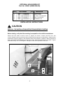
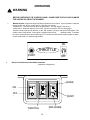
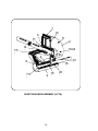
Form 1-738 R
JULY, 2003
INSTALLATION a nd OPERATING
INSTRUCTION MANUAL
1.8
PART NO.
&
2.0
CU. YD. INSERT HOPPER SPREADER
with Replaceable conveyor Floor
CAPACITY
LENGTH
WEIGHT (EMPTY)
62209 (STEEL)
1.8 CU YD
7 FT.
980 LBS.
62517 (STEEL)
2.0 CU YD
8 FT.
1015 LBS.
62504 (STEEL)
SPINNER ASSEMBLY
62505 (STEEL)
SPINNER ASSEMBLY (EXT.)
INDEX
SAFETY ALERT ...............................................................................................................
SPREADER ASSEMBLY INSTRUCTIONS .......................................................................
ELECTRIC THROTTLE CONTROLS ................................................................................
CENTER HIGH MOUNT STOP LAMP ...............................................................................
HYDRAULICS
...............................................................................................................
SPREADER OPERATION .................................................................................................
SPREADER MAINTENANCE ............................................................................................
SPREADER PARTS LISTS & EXPLODED VIEW
• HYDRAULIC MOTOR ....................................................................................................
• HYDRAULIC DRIVEN SPREADERS ............................................................................
• ENGINE DRIVEN SPREADERS ...................................................................................
• DURST GEAR BOX ASSEMBLY ....................................................................................
• SUPERIOR GEARBOX ASSEMBLY ..............................................................................
• SPINNER ASSEMBLY
•• SHORT ............................................................................................
•• INTERMEDIATE “NEW STANDARD EQUIPMENT” ......................
•• EXTENDED .....................................................................................
• ELECTRIC CONTROLS
•• HONDA ENGINE .............................................................................
•• BRIGGS & STRATTON ENGINE ....................................................
• CONTROL BOX .............................................................................................................
• OPTIONAL COMPONENTS ..........................................................................................
• PARTS LIST SHIPPING CARTON ................................................................................
NAME PLATE INFORMATION ..........................................................................................
WARRANTY INFORMATION .............................................................................................
WARRANTY REGISTRATION CARD ................................................................................
2
3
6
10
12
14
18
- 5
- 9
- 11
- 13
- 17
19
20
28
36
38
-
40
42
44
- 41
- 43
- 45
46
48
50
52
53
54
55
55
-
27
35
37
39
47
49
51
53
Meyer Products and Diamond Equipment reserves the right, under its continuing product improvement program, to change construction or design details,
specifications and prices without notice or without incurring any obligation.
Meyer Products
18513 Euclid Ave. • Cleveland, Ohio 44112-1084
Phone 486-1313 (Area Code 216)
www.meyerproducts.com• email [email protected]
1
Diamond Equipment
6 Angell Lane• Damariscotta, ME 04543-9720
Phone 563-2227(Area Code 207)
www.diamondplow.com • email [email protected]
THE BEST SAFETY
DEVICE IS A
CAREFUL OPERATOR!
SAFETY ALERT SYMBOL
!
THIS SYMBOL MEANS ATTENTION!
BECOME ALERT! YOUR SAFETY IS INVOLVED!
PLEASE READ AND UNDERSTAND COMPLETELY BEFORE DOING!
SAFE EQUIPMENT INSTALLERS
!
AND
OPERATORS:
TURN OFF ALL POWER BEFORE PERFORMING ANY SERVICE OPERATIONS
•
FOLLOW RECOMMENDED OPERATING PROCEDURES.
•
KEEP EQUIPMENT IN SAFE OPERATING CONDITION AT ALL TIMES.
•
RECOGNIZE AND AVOID HAZARDS WHILE OPERATING, SERVICEING AND
MAINTAINING EQUIPMENT.
!
REFER TO THE ENGINE OPERATING & MAINTENANCE MANUAL FOR
SPECIFIC SAFETY PRECAUTIONS FOR THIS ENGINE.
! CAUTION
1. KEEP ALL SHEILDS IN PLACE.
2. MAKE CERTAIN EVERYONE IS CLEAR BEFORE
STARTING MACHINE OR MOVING VEHICLE.
3. KEEP HANDS, FEET, AND CLOTHING AWAY FROM
ALL POWER DRIVEN PARTS.
4. DISENGAGE P.T.O., SHUT OFF HYDRAULIC VALVE
AND SET PARKING BRAKE BEFORE LEAVING
OPERATOR’S POSITION. MAKE SURE ALL
MOVEMENT HAS STOPPED BEFORE SERVING,
UNCLOGGING OR CLEANING MACHINE.
5. USE FLASHING LIGHTS WHEN OPERATING
MACHINE.
6. MAKE SURE MACHINE IS SOLIDLY SUPPORTED
WHEN IT IS BEING MOUNTED, DISMOUNTED, OR
STORED.
IF DEFACED • ORDER PART NO. 04049 045 00
NOTICE:
Instructional Material And Parts Lists Included In This Manual Are Subject To Change Without Notice.
2
INSTALLATION AND ASSEMBLY INSTRUCTIONS
INSTALLATION INSTRUCTIONS:
The 1.8 and 2.0 Series Spreaders can mount and store as a single unit and will mount on most medium,
heavy-duty/pick-up trucks as well as 1 ton trucks
WARNING
THE SPREADER UNIT MUST BE SECURELY FASTENED TO THE VEHICLE. FAILURE TO NOT
PROPERLY RESTRAIN THE UNIT COULD PERMIT THE UNIT TO BREAK FREE FROM THE TRUCK
AND CREATE A POTENTIAL FOR A LIFE THREATENING ACCIDENT.
DO NOT OVERLOAD THE VEHICLE. It is quite possible to overload the vehicle by improperly mounting or over
loading the spreader. This could result in dangerous stability and braking problems. Always consult and follow the
truck manufacturer’s instructions.
WARNING
BEFORE BEGINING ANY INSTALLATION ON THIS UNIT, disconnect the spreader battery negative cable if
already installed.
1. Place the Spreader in the rear of truck with the engine/hydraulic motor to the rear of the truck. Center the
spreader (side to side) in the truck. The spreader should extend past the rear of the outer most part of the truck
(i.e: truck bed, bumper) approximately 18 inches.
CAUTION
INSURE THAT THE SPREADER CANNOT TIP WHEN THE SPINNER ASSEMBLY IS ATTACHED
SPINNER ASSEMBLY
a.
Raise engine shroud and prop it open with the support rod. (If engine driven model)
b.
Slide the spinner frame assembly into the rear of the longitudinal with the spinner back plate toward the
rear.
c.
Bolt the spinner to the longitudinals using the four (4) 3/8” x 1” bolts, 3/8” flange nuts and flatwashers from
hardware bag located on the spinner. Using one (1) 3/8” x 1” bolt, flatwashers and flange nut from hardware
bag, bolt the top portion of the spinner back plate to the engine plate.
d.
Install roller chain between the gear box sprocket and the spinner sprocket.
Make sure sprockets are in line with each other. The roller chain is tightened first by loosening all four (4)
3/8” bolts on the back plate; then pull the entire bearing/shaft assembly in such a way to achieve the proper
amount of chain tension. Make sure the spinner shaft is straight up and down before
re-tightening.
2. Reposition the spreader in the truck, just short of making contact with the rearmost part of the truckbed,
bumper, pintle hook etc. Bolt the unit to the truck using a minimum of four (4) 1/2” - grade 5 bolts and
corresponding washers and locknuts.
The spreader is designed to sit flat on the bed of the truck, supported by the longitudinals/sides.
DO NOT SUPPORT THE SPREADER BY THE BODY JACKS ALONE!! UNIT IS NOT DESIGNED FOR
CHASSIS MOUNT APPLICATIONS!
3
OPTIONAL HOLD-DOWN KIT
Part No. 62562 (00002-306-00)
ITEM
1
2
3
4
5
PART NUMBER
62602
62807
20307
62604
62605
QTY.
04068-038-00
04048-504-02
04003-804-06
04003-801-11
04004-002-16
4
4
4
4
8
DESCRIPTION
Ratchet/Strap
Bolt, 1/2” Eye
Locknut, 1/2-13 Esna ZP
Nut, 1/2-13 Hex ZP
Flatwasher, 3/4"
INSTALLATION INSTRUCTIONS
CAUTION
READ ALL THE INSTALLATION INSTRUCTIONS BEFORE STARTING
Before starting, verify that this mounting is acceptable to the vehicle manufacturer.
Attach the hold down at each corner of hopper as shown. Locate and drill four .531
(17/32”) diameter holes for eye-bolts in the truck bed (position may vary from that shown). Straps must be
positioned at opposing angles so that spreader cannot slide forward or rearward. Mount eye-bolts as
shown, with locknuts and flatwashers on the bottom side. Assemble ratchet/strap to eye-bolts. Tighten
hold downs evenly. Do not over tighten damage will result to the spreader or the truck.
1
2
4
4
5
ASSEMBLY INSTRUCTIONS
1. Install roller chain between the gear box sprocket and the spinner sprocket. Make sure sprockets are in line with
each other. The roller chain is tightened, first by loosening all four (4) 7/16" bolts on the back plate. Then, pull the
entire bearing bracket assembly in such a way to achieve the right amount of chain tension. Make sure spinner
shaft is straight up and down before retightening.
2. Electric Throttle: Go to page 8.
Manual Throttle: Installation or replacement with gasoline engine do the following: Attach "Z" end of throttle
cable to engine throttle. Anchor brass shoulder end to engine with hold down. Drill 1/2" hole in truck cab for
control end of cable. The throttle handle can be removed to put throttle cable through drill hole. DO NOT MAKE
SHARP BENDS OR KINK THROTTLE CABLE. Use rubber grommet, supplied, in hole that you just drilled to
protect cable. Do not mount throttle cable assembly to switch bracket yet; upcoming assembly instructions will
become more difficult if throttle cable is mounted now.
Refer to diagram "A" on page 6-7 for installation and part ordering.
3. Run the (2) conductor cable (#16), which leads from the soleniod (white lead), and the electric clutch (black
lead) through the same hole which you put your throttle cable through.
4. Wire-up (2) conductor cable (#16) to the control panel as Diagram "A" shows; making sure the white conductor
is connected to the lone terminal of the push button (#3) and the black conductor to the lone terminal of the on/
off button (#7). The red wire (#6) which is about 4 ft. long, must be connected into the vehicles electrical system
so that it provides power to switch bracket. Control panel will not function without this connection.
5. Find a convenient location for the control panel and drill (2) 13/32" holes on 3" hole centers. Before mounting,
you may want to mount throttle cable to control panel according to diagram "A." Using the 3/8" x 1" bolts,
lockwashers and nuts, mount panel securely.
6. When finished, make sure all wires are away from moving parts and lower engine shroud.
CAUTION!
Never operate machine with engine shroud in the upright position. Never climb into hopper while the engine is
operating. SERIOUS INJURY or DEATH MIGHT OCCUR.
WARNING
Consult vehicle manufacturer for acceptable mounting locations. Improperly mounting the control box could interfere
with air bag(s) and the other functions of the occupant protection systems, such as knee bolsters!
Before mounting, you may want to mount throttle cable to control panel according to Diagram “A”.
Using the 3/8” x 1” bolts, lockwashers and nuts, mount panel securely.
5
6
1
FRONT VIEW
THROTTLE
3
17
7
2
4
5
9
6
REAR VIEW
WHITE
BLACK
BATTERY HOLD
DOWN POST
16
BLACK
WHITE
14
20
21
DIAGRAM "A"
18
19
BATTERY
10
12
15
11
13
STARTER
CHARGER
WIRE
TABLE FOR
DIAGRAM "A"
ITEM
PART NO.
QTY.
DESCRIPTION
62116
00001-598-00
1
Carton, Electrical Cab Controls
1
61216
00104-824-00
1
• Switch Bracket
2
62047
04640-004-00
1
• On/Off Plate
3
62038
04144-008-00
1
• Push Button Switch
4
62042
04616-013-00
1
• 16 Ga. Black Wire (6" Long)
5
61188
04143-024-00
1
• Throttle Cable Assembly
6
62043
04616-032-00
1
• 16 Ga. Red Wire (4' Long)
7
62049
04640-013-00
1
• On/Off Switch
8
62805
04638-040-06
1
• Insulated Spade Terminal
9
92805
04638-040-06
2
• Insulated Spade Terminal
10
62040
04604-004-00
2
• 19" Battery Cable
11
62046
04638-039-04
1
• Insulated Ring Terminal
12
61179
04146-005-00
1
• Grounded Solenoid
13
61167
04138-017-00
1
• Electric Clutch
14
•• Now part of item 13
15
61213
04616-067-02
1
• Starter Cable
16
62107
00111-162-00
1
• Cable Assembly, Rear Half
17
61152
00104-847-00
1
• Assembly, Control Panel **
18
62108
00111-163-00
1
• Cable Assembly, Front Half
19
• Tubing, Shrinkable 1/8" x 2"
Not Used
20
62105
04067-033-00
1
• Boot, Battery Cable (Battery End)
21
62106
04067-033-00
1
• Boot, Cable (Solenoid End)
Parts indented are included in the carton, bag or assembly under which they are indented.
** Includes items 1- 9
7
INSTALLATION INSTRUCTION FOR
ELECTRIC THROTTLE CONTROLS
(FACTORY INSTALLED ACTUATORS)
WARNING
BEFORE BEGINING ANY INSTALLATION ON THIS UNIT, disconnect the spreader battery
negative cable if already installed.
PREPARING UNIT:
1.
Spreaders with factory installed throttle controls do not require installer hook-up to the engine. The
actuator has been installed and tested at the factory.
2.
Raise the engine shroud and securely prop it in place with the prop rod. The installer will have to remove
the ties securing the coiled actuator cable to the top of the engine.
3.
The throttle actuator cable plugs into the in-cab control panel after being routed from the cab of the
vehicle to the rear of the mounted spreader.
4.
Select a suitable location in the cab of the vehicle to mount the throttle control box.
WARNING
Consult vehicle manufacturer for acceptable mounting locations. Improperly mounting the control box could
interfere with air bag(s) and the other functions of the occupant protection systems, such as knee bolsters!
5.
After the location of the control panel is determined, the cable must be routed to the front of the spreader,
Route cable under the cab and up to the front of the spreader securing as needed. Allow enough cable for
the control panel to be mounted in the cab.
6.
The routed cable must be clear of all moving or hot parts on the sreader or vehicle. Secure the cable with
the ties provided. Excess cable must be coiled up and secured. Apply dielectric grease on Item # 21
page 46 for protection from salt spreading envoirment.
7.
Mount the control panel (with screws supplied).
8.
For permanent cable mount at rear of the truck, a mounting bracket is supplied.
9.
Install a 12 volt battery with 40 ampere hour rating, recommended for winter use (if not already done). The
battery hold-downs furnished will accept any 2 SM Series battery.
8
WARNING
USE SAFETY GLASSES OR OTHER FACE PROTECTION AGAINST POSSIBLE BATTERY
EXPLOSION. DO NOT SMOKE AND AVOID OTHER SOURCES OF IGNITION.
10.
Attach the positive battery cable (each end should have a rubber boot) to the positive terminal of the
solenoid and to the positive terminal of the battery. Make sure these protective boots are covering the
positive terminal post on the battery and on the solenoid. Attach one end of the remaining battery cable
to the negative terminal of the battery.
11.
Connect the negative battery terminal to the battery hold down post. When finished, make sure all
wires are away from moving parts and lower engine shroud.
12.
Plug cable from spreader into socket mounted on truck.
WARNING
Never operate machine with engine shroud in the upright position. Never climb into hopper
while the engine is operating or capable of being operated.
SERIOUS INJURY or DEATH MIGHT OCCUR.
NOTE: Read and fully understand the owners manual supplied by the engine manufacturer
before operating this equipment. Not doing so, endangers your safety and the warranty
of the engine.
9
CENTER HIGH MOUNT STOP LAMP (CHSML)
WARNING
Federal Motor Vehicle Safety Standards require all Trucks, Buses, and Multipurpose passenger
vehicles, manufactured on or after September 1, 1993, with a gross vehicle weight rating (GVWR)
of 10,000 lbs. or less and overall width less than 80" must be equipped with a Center Height
Mount Stop Lamp (CHMSL).
If the original equipment CHMSL is obscured, an auxiliary CHMSL must be installed to bring
vehicle back into compliance with Federal Regulations.
Electrical Connection for Auxiliary CHMSL:
(Notes for all truck makes)
1.
Use high quality butt connectors and shrink wrap on all electrical splice connections. Wire should be routed
and secured to protect against abrasion, sharp edges, excessive movement. It is highly recommend that
wiring to be placed in convoluted tubing and secured with tie wraps.
2.
When drilling holes, any bare metal should be coated with a rust preventative, use appropriate size grommets
and seal hole with appropriate sealant.
3.
Allow for normal movement / twisting between cab and chassis / pickup box when routing wires.
4.
When spreader is removed from the truck, the OEM CHMSL must be reconnected.
WARNING
Consult the truck manufacturer for an approved method of connecting an auxiliary CHMSL to the particular truck
which is to carry the Spreader. Methods vary with truck models, optional equipment and years of manufacture.
IMPROPER CONNECTIONS COULD RESULT IN A VARIETY OF PROBLEMS AFFECTING CRITICAL SYSTEMS
SUCH AS BRAKING, ELECTRICAL AND EMISSION ! DON'T GUESS !
PV Spreader CHMSL Installation:
Mount power cable (04616-075-00) with plug at rear of truck frame and route to truck CHMSL power feed. Trim
excess cable length, attach white wire to suitable ground, attach black wire to truck's CHMSL power feed.
Connect cable on spreader to CHMSL power cable.
When the spreader is removed from the truck, the OEM CHMSL must be reconnected.
10
CENTER HIGH MOUNTING STOP LIGHT
ITEM
PART NUMBER
62097
62714
62715
62364
62738
62283
62739
1
2
3
4
5
6
00002-144-00
04605 153 00
04605 154 00
04605 155 00
04616 075 00
00111 339 00
00111 428 00
QTY.
1
1
1
1
1
1
1
DESCRIPTION
Kit, Center High Mount Stop Light
• Lamp, Stop
• Grommet
• Cable, Light Power
• Cable, Stop Lamp
• Weld, Stop Lamp Bracket - Hydraulic Units ONLY
• Hardware Bag - Not Shown
2
1
3
(GAS ENGINE)
5
2
1
(HYDRAULIC)
4
11
HYDRAULICS
WARNING
LEAKING HIGH PRESSURE FLUIDS CAN INJECT THEMSELVES UNDER THE SKIN OF PERSONS
NEAR A LEAK, CREATING GRAVE MEDICAL RISKS. TAKE CARE TO AVOID EXPOSURE TO
HIGH PRESSURE FLUIDS.
1 . Hydraulic components should be kept as clean as possible during assembly operations.
2. Galvanized pipe and pipe fittings must not be used because flaking or galvanizing material can cause
damage to major hydraulic components.
3. A pipe joint sealant, compatible with hydraulic oil, must be applied to all screwed fittings. (Teflon tape is not
recommended.)
4. Hose should be protected where severe wear may be caused by vibration or sliding movement.
5. Long runs of hose should be supported by tie wiring or clamping.
6. Pressure and return hoses, connected to hydraulic motors, may be reversed for proper motor rotation.
Spinner rotates in a clockwise direction when looking down from top.
7. Use hose manufacturer’s recommendations for fitting re-useable hose ends.
8. Hydraulic pumps must be mounted so shaft rotates in direction of arrow.
9. Locate reservoir as close to pump as possible. It may be installed on truck frame or truck box.
10. Hydraulic return line filter is screwed directly onto reservoir with cartridge down. Oil must flow through filter
in direction of arrow on filter.
11. Install the quick connect couplings so that when disconnected, there is a male and female on the truck as
well as on the spreader. This way, hoses will always be hooked up properly. and hose ends can be coupled
together when spreader is in storage to prevent system contamination.
12. See page 13 for valve assembly
13. Operate hydraulic system for several minutes to warm up. Check all connections for leaks.
14. After running, refill reservoir to three fourths full.
CONTROL AND HYDRAULIC SYSTEM SPECIFICATIONS
* Hydraulic Oil ................................. Good Grade of MS10W Hydraulic Oil Which has
wear, oxidation and foam inhibitors.
* Oil Filter ........................................ 10 Micron Element Return Line Filter.
* Relief Valve Setting ...................... 1500 PSI
* Oil Flow ......................................... 0 - 10 GPM
12
SINGLE FLOW CONTROL VALVE
DUAL FLOW VALVE/STAND
INSTALLATION INSTRUCTIONS
61190
(04105-306-00)
*
FLANGE PLATE
00105-873-00
1.
IMPORTANT: A pipe joint sealant compatible with
hydraulic oil must be applied to all screw fittings.
(Teflon Tape Sealant Is Not Recommended)
2.
Hose ends connected to flow valve must be of the
"swivel" type.
3.
CAUTION: Over tightening of the fittings in flow valve
may cause damage to valve body.
4.
Approximately 8" of hose slack must be realized
between the flow valve and valve stand after the
flow valve has been completely plumbed. If this
condition does not exist after the plumbing has
been completed, removal of valve will require hoses
to be removed at opposite end of valve.
5.
Assembly of valve on stand:
BOTTOM VIEW
A-A
(SHOWN W / O FITTINGS)
A
A
a.
Cut a 5" x 5" square opening in floor board of
truck where the valve stand is to be located.
b.
Bolt valve stand halves together forming a
"box" over the 5" x 5" square opening. NOTE:
When bolting valve stand halves in place,
make sure holes in flanges align with holes in
flange plate.”*”
c.
Bolt flange plate to VALVE (Use (2) 1/4" x 3"
bolts, lockwashers, etc.)
d.
Insert hoses through floor opening and valve
stand and connect appropriate hoses (see
instructions #1 thru #4) to flow valve.
e.
Bolt flange plate to valve stand flanges.
8.0"
HOSE SLACK
AFTER PLUMMING
VALVE STAND
(2) HALVES
00105-874-00
TRUCK CAB
FLOOR BOARD
13
OPERATION
WARNING
BEFORE OPERATING THE CONTROL PANEL - MAKE SURE THAT NO ONE IS INSIDE
THE HOPPER OR NEAR THE SPINNER.
1.
Manual Throttle: All gasoline engine models come with a control panel. If your spreader is a manual
throttle model, look at your control panel. It will have (3) controls
mounted on it. The one on the far left is the start button. The right toggle is the electric
clutch control. When the switch is in the “OFF” position, the electric clutch is disengaged
and the conveyor and spinner will stop. In the “ON” position, conveyor and spinner will operate. The
middle control is the throttle. Your engine is equipped with a semiautomatic choke. To activate
the choke, pull the throttle cable all the way out. To remove the choke function when engine us warm,
push throttle cable in, to desired engine RPM.
ON
THROTTLE
START
2.
OFF
Electric Throttle Control Panel Switch Functions
(Sequence of Operations)
CHOKE
ON
OFF
START
RED LENSE
THROTTLE
14
Electric Throttle Control Panel Switch Functions Cont.
A. ON/OFF
System power activated (ready to start). Spreader engine is not running.
Spreader conveyor is not engaged.
B. START (Engine only)
1.
Open fuel shut off valve on engine.
2.
On
On switch depressed.
3.
Choke
(cold engine ) Hold down for 5 seconds to move the throttle actuator to
the choke position.
Note: Choking a warm engine may not be necessary.
4.
Start
Hold down until engine starts.
4a.
On models with 6.5 HP at temperatures under minus 20o F (minus 29o C) it mat be
necessary to start the engine manually.
5.
Turtle
Deceases throttle speed - adjust as engine warms up. Will stop the choke function.
Rabbit
Increases throttle speed.
C. TO ENGAGE Spreader Conveyor
1. Push CONVEYOR switch only after you are sure no one is in the hopper or near the spinner! This lights up
the red indicator light, if light does not light, take care to verify that the light is not malfunctioning.
D. TO CONTROL Conveyor Speed.
1. Hold RABBIT to increase speed. NOTE: Do not hold switch in HI position after the desired RPM is achieved
or you will choke and/or stall the engine.
2. Hold TURTLE to decrease speed.
E. TO DISENGAGE Spreader Conveyor.
1. Tap START switch momentarily so that red indicator light goes out. Do not fully depress the START switch,
only half way is needed. Only the conveyor stops, the engine continues to run.
F. TO TURN ENGINE OFF (with or without conveyor running).
1. Depress LO on throttle control to reduce setting to idle (this prevents engine flooding and hard starting).
2. Push OFF position on the ON/OFF switch.
NOTE: OFF can be pushed at anytime during spreader operation to cut power to the unit . However, you
should normally use steps under F above.
(Once the off switch is depressed - the starting procedure must be followed for engine re-start.)
G. Do not attempt to start the engine with the conveyor engaged. (CONV switch light will be lit to indicating its'
being on.)
H. Close fuel shutoff valve on engine if unit is to be transported while not running.
WARNING
1. As with all power equipment, safety is the number one concern.
2. Do not operate this equipment until you fully understand how it functions.
3. Before starting engine, be sure that no one is near the rear of the unit and that no one is inside the
unit!
4. Do not start the engine or engage the conveyor (which is interconnected to the spinner); until everyone
is clear from moving parts and flying material from the spinner.
15
SPREADER OPERATION
A. Start the engine and engage the clutch. The amount of material spread, depends on engine speed and gate
opening. Decreasing RPM and/or gate height will decrease amount spread; the inverse holds true also.
Notice that the electric clutch can be engaged or disengaged at any time and at any engine RPM. However,
since engagement time and torque is almost instantaneous, to prevent premature spinner chain failure and
chain tension loss, it is recommended that the electric clutch be engaged at the lowest possible RPM
without stalling the engine.
If the truck is to be driven for an extended period of time while the spreader is not operating, it is RECOMMENDED
to turn off the gas at the carburetor inlet to prevent the carburetor from over filling with fuel.
Before loading the spreader the first time, start and stop the conveyor several times to break in the clutch.
WARNING
ALWAYS STAND AT A SAFE DISTANCE AWAY FROM THE SPINNER WHILE OPERATING
ALWAYS WEAR EYE PROTECTION WHEN OUTSIDE OF THE TRUCK CAB WHILE
SPREADER IS RUNNING.
B. Spread pattern depends on baffle settings and spinner RPM. Maximum spreader width is 30 ft.
1. Speeding up or slowing down the engine will increase or decrease spread pattern width.
2. Internal baffle adjustments will move the spread pattern to the right or left.
3. External baffle adjustments will block spreading to the right or left side.
DESIRED SPREAD PATTERN
BAFFLE SETTING
INTERNAL
EXTERNAL
CENTERED BEHIND TRUCK
BOTH DOWN
ALL THREE UP
BEHIND TRUCK
LEFT
RH - DOWN
LH - UP
RH - DOWN
LH - UP
BEHIND TRUCK AND RIGHT
RH - UP
LH - DOWN
RH - UP
LH - DOWN
WINDROW BEHIND TRUCK
RH - DOWN
LH - DOWN
ALL - DOWN
AND
4. External Baffles can be lowered to an intermediate position to baffle down the particles that may otherwise
leave the spinner at a high trajectory.
16
June, 2000
SERVICE BULLETIN NO. 178
1.8, 2.0 and MDV Insert Hopper Spreader
Briggs & Stratton Corporation and Honda Engine Motor of America have stated in
their manuals:
DO NOT TRANSPORT ENGINE WITH FUEL IN TANK OR WITH FUEL
SHUT-OFF VALVE OPEN.
Failure in doing this may cause the engine crankcase to fill with fuel. If this occurs the
engine warranty will be void by the engine manufacturer. It is the responsibility of the
end user to ensure that the fuel shut-off is closed when the engine is not in operation.
17
WARNING
MAINTENANCE
DO NOT ATTEMPT TO LIFT THE SPREADER BY THE CENTER LIFT OR CORNER LIFT HOOKS
WITH MATERIAL IN THE SPREADER.
BEFORE BEGINNING ANY MAINTENANCE ON SPREADER, DISCONNECT SPREADER
BATTERY LEADS.
1.
Grease idler bearings on idler shaft takeup assembly, outboard bearing on gearbox output shaft, and
lower spinner bearing every ten hours of operation.
2.
Grease input shaft bearing on gearbox every fifty hours of operation. CAUTION! Over greasing may
cause seal damage. The gearbox must be filled to oil level plug with SAE 90 gear type lubricant. Keep
breather plug clean.
3.
Drag chain slack on V-boxes should be checked periodically and taken up if distance between center line
of rear sprocket and point where chain contacts lower flange on longitudinal is less than eight (8) inches.
CAUTION! Over tightening conveor chain can cause serious drive train problems. Above distance must
not exceed 20 inches.
4.
If the spreader is equipped with a gasoline engine, it should be maintained per engine manufacturer's
instruction. (Instructions and parts book is enclosed.)
5.
V-belt tension must be maintained. The v-belt can be tightened by loosening engine hold-down bolts and
sliding engine as required. CAUTION! Over tightening of v-belt may damage gearbox.
6.
Roller chain tension must be maintained. It is adjusted by loosening the spinner mounting bearings and
sliding the bearings. Make sure the spinner shaft is straight up and down before retightening. Oil chain
often and at end of season.
7.
When the box is not in use, it should be washed out. If the box is put in storage, all surfaces should be
oiled or painted after washing.
8.
For HYDRAULIC SPREADERS, maintain oil level three fourths (3/4) full in reservoir with clean high grade
non-foaming hydraulic oil; recommended viscosity 100-200 SSU. Operating temperature should be limited
to 180°F. Replace filter cartridge No. 62382 (04104 005 00) at least twice a year.
9.
If chain becomes stuck or "froze" to the floor to the point where the clutch cannot pull the load, never
attempt to free chain using a pipe wrench or any other tool on the output shaft. The gearbox is designed
to accept torque from input shaft only. Trying to turn output shaft will strip the gears, thus voiding the
warranty.
10.
To minimize problems and extend the life of the Electric Clutch, the following is highly recommended.
a.
Before starting unit, make sure the drag chain is free (not stuck or "froze" to the
floor). If the drag chain is stuck, this can cause the clutch to burnup.
b.
After the using season is over, remove clutch from unit, and clean thoroughly.
c.
After cleaning, coat both mating surfaces of the clutch with oil or light weight
grease.
NOTE: The Oil or Grease must be removed prior to the next using season.
18
11
1
2
3
4
6
5
7
89
12
13
11
15
11
16
17
14
10
PARTS LIST FOR HYDRAULIC MOTOR
60324 (04101-035-00)
PARTS LIST
ITEM
1
2
3
4
5
6
7
8
9
10
11
12
13
14
15
16
17
PART NUMBER
QTY.
DESCRIPTION
20644
——————
62118
——————
62756
——————
62757
21203
62758
62809
——————
62759
62760
62761
04101-035-01
——————
04101-102-02
——————
04101 035 05
——————
04101 035 07
04009 002 02
04101 035 09
04101 035 10
——————
04101 035 12
04101 035 13
04101-035-14
4
1
1
—
1
—
1
1
1
1
—
1
1
4
Screw, 5/16" - 24 x 7/8"
Seal
Flange, Mounting (4 Bolt)
Seal, O-Ring
Race, Bearing
Seal, O-Ring
Bearing, Thrust Needle
Key, 1/4" x 1" Woodruff
Shaft, Output
Housing
Seal, O-Ring
Drive (For 04101 035 00)
Plate, Spacer
Screw, 5/16" - 24 x 1 1/2" Cap
62814
62405
62762
04101 035 15
04101 035 17
04101 035 18
04101 035 21
1
1
7
1
62406
62359
04101 102 09
04101 035 98
1
1
Gerotor Set (For 04101 035 00)
Cap, End
Washer, Seal
Repaired Motor
(for 04101 035 00)
Seal Kit (Char-Lynn)
Seal Kit (White)
19
20
19
27
used with
gas engine?
56
43
28
29
2
30
18
25
21
87
5
28
29
43
26
29
11
28
?
34
23
3-43
44 41
1
40
10
12
6
HYDRAULIC DRIVEN HOPPER SPREADER
13
16
35
54
42
31
19
12
20
16
34
21
4
54
17
13
19
18
PARTS LIST FOR HYDRAULIC DRIVEN
HOPPER ASSEMBLIES
(Carbon Steel) After 11-1998 S/N 85171
1.8 Cu. Yd.(62520) - 2.0 Cu. Yd. (62521)
PARTS LIST
ITEM
1
2
3
4
5
6
7
8
9
10
11
12
13
14
15
16
17
18
19
20
21
22
23
N/S
N/S
N/S
24
25
26
27
28
29
30
31
32
33
34
35
36
37
38
39
40
41
PART NUMBER
62740
62741
61178
62615
62742
61201
61158
62129
62617
20329
20066
20327
62743
61165
22418
22419
62641
61170
62644
62570
61172
61171
61169
62281
60324
62118
62406
62359
62201
62202
20049
20353
62073
62326
62408
62745
62320
62310
62280
20354
20384
62746
20305
62270
61173
62002
61174
62755
00115-156-08
00115-156-10
04132-074-00
04003-033-04
00115-167-01
04009-001-01
04043-013-00
04043-016-00
04003-005-14
04004-001-09
04033-003-04
04004-001-07
04003-806-12
04080-053-00
04003-002-04
04003-002-02
04003-806-13
00101-326-00
04003-034-01
04003-806-03
00101-325-00
06022-001-00
04624-001-01
00110-819-00
04101-035-00
04101-102-02
04101-102-09
04101-035-98
06011-000-00
04008-001-00
04003-003-03
04004-002-08
00105-302-00
00106-366-00
04003-802-05
04007-005-04
00115-173-01
00115-139-01
00110-817-00
04004-002-09
04010-003-02
04003-033-12
04003-804-02
00101-636-00
04043-017-00
04045-023-00
04045-021-00
04045-025-00
21
QTY.
DESCRIPTION
1
1
1
1
1
1
1
1
4
4
4
4
8
2
2
4
16
2
8
8
1
1
1
1
1
1
1
1
1
4
8
15
1
2
4
2
2
2
1
2
2
3
5
1
2
2
Weld, 1.8 Hopper
Weld, 2.0 Hopper
Gearbox, Assembly
Bolt, 3/8-16 x 1-1/4 Car. GR. 5 ZP
Guard, Conveyor
Key, 1/4” X 7/8” Woodruff
Weld, Drag Chain, 7 Ft.
Weld, Drag Chain, 8 Ft.
Bolt, 1/2-13 x 3/4 HH GR5 ZP
Lockwasher, 1/2” Med Split ZP
Bolt, 3/8-16 x 1-1/4 HH GR5 ZP
Lockwasher, 3/8” Med Split ZP
Nut, 3/8-16 Serrated Flange SS
Bearing, 2 Bolt Flange
Bolt, 5/16-18 x 1 HH GR5 ZP
Bolt, 5/16-18 x 3/4 HH GR5 ZP
Nut, 5/16-18 Serrated Flange SS
Plate, Front Bearing
Bolt, 1/2-13 x 1 Car Sht NK
Nut, 1/2-13 Hex ZP
Weld, Idler Shaft
Sprocket, Drag Chain
Knob, Hand
Weld, Feedgate
Motor, Hydraulic
Flange Mounting (4Bolt)(Char-Lynn)
Seal Kit (Char-Lynn)
Seal Kit (White)
Plate, Motor Mtg.
Bushing, 3/8” I.D. x 5/8” O.D.
Bolt, 3/8-16 x 1 HH GR5 ZP
Flatwasher, 3/8” U.S.S. ZP
Coupling, Shaft
Setscrew 1/2” x 6”
Nut, 1/2-13 Hex Jam ZP
Setscrew, 1/4-20 x 3/8” Al. HD
Shield, Rep. Chain 7 Ft.
Shield, Rep. Chain 8 Ft.
Handle
Flatwasher, 7/16” U.S.S. ZP
Pin, 1/8” x 1” Cotter
Bolt, 3/8-16 x 3/4 Car GR5 SS
Locknut, 3/8-13 Nylon Insert ZP
Bar, Pivot
Drag Chain w/Links
Connecting Link Only
Pin, Master for Chain w/o Cotter
Pin, Cotter Only
22
19
27
used with
gas engine?
56
43
28
29
2
30
18
25
21
87
5
28
29
43
26
29
11
28
?
34
23
3-43
44 41
1
40
10
12
6
16
13
HYDRAULIC DRIVEN HOPPER SPREADER
35
54
42
31
19
12
20
16
34
21
4
54
17
13
19
18
PARTS LIST FOR HYDRAULIC DRIVEN
HOPPER ASSEMBLIES
(Carbon Steel)
1.8 Cu. Yd.(62520) - 2.0 Cu. Yd. (62521)
Continued
PARTS LIST
ITEM
42
43
44
45
46
47
48
49
50
51
52
53
54
PART NUMBER
62497
62571
62009
62572
62318
62292
62747
62640
62314
62364
62283
62714
62715
62284
62000
61163
62354
04049-002-00
04049-165-00
04049-182-00
04049-195-00
00115-172-01
00115-109-01
04003-018-04
04003-032-06
00115-154-01
04605-155-00
00111-339-00
04605-153-00
04605-154-00
00102-347-00
04031-010-00
04080-005-00
04076-100-00
QTY.
3
1
2
1
1
1
4
8
1
1
1
1
1
2
2
1
1
23
DESCRIPTION
Decal, Meyer
Decal, Serial (w/Pat. Nos.)
Decal, Danger (Conveyor)
Decal, Motor
Floor, Forming 7 Ft.
Floor, Forming 8 Ft.
Screw, 3/8-16 x 1 3/16 Slt. Fl. HD
Bolt, 5/16-18 x 3/4 Car GR5 SS
Guard, Shaft
Cable, Light Power
Weld, Stop Lamp Bracket
Lamp, Stop (Ctr Hgh Mt)
Grommet, Mtg
Sprocket, Drive (w/set screws)
Key, 1/4” Square x 2”
Bearing, Drive
Wiper, Chain
24
19
27
used with
gas engine?
56
43
28
29
2
30
18
25
21
87
5
28
29
43
26
29
11
28
?
34
23
3-43
44 41
1
40
10
12
6
16
13
HYDRAULIC DRIVEN HOPPER SPREADER
35
54
42
31
19
12
20
16
34
21
4
54
17
13
19
18
PARTS LIST FOR HYDRAULIC DRIVEN
HOPPER ASSEMBLIES
(Stainless Steel) After 11-1998 S/N 85171
1.8 Cu. Yd.(62522) - 2.0 Cu. Yd. (62523)
PARTS LIST
ITEM
1
2
3
4
5
6
7
8
9
10
11
12
13
14
15
16
17
18
19
20
21
22
23
N/S
N/S
N/S
24
25
26
27
28
29
30
31
32
33
34
35
36
37
38
39
40
41
PART NUMBER
62748
62749
61178
62777
62317
61201
61158
62129
62750
22380
62695
22379
62743
61165
62751
62752
62641
62268
62753
62754
61172
61171
61169
62282
62398
62118
62406
62359
62368
62339
62697
22230
62073
62326
62336
62745
62321
62311
62280
62808
20384
62746
62638
62270
61173
62002
61174
00115-156-09
00115-156-11
04132-074-00
04003-033-05
00115-167-02
04009-001-01
04043-013-00
04043-016-00
04003-005-56
04004-001-16
04003-003-26
04004-001-14
04003-806-12
04080-053-00
04003-002-24
04003-002-23
04003-806-13
00101-326-01
04003-034-14
04003-806-16
00101-325-00
06022-001-00
04624-001-01
00110-819-01
04101-035-00
04101-102-02
04101-102-09
04101-035-98
06011-000-01
04008-007-00
04003-003-20
04004-002-20
00105-302-00
00106-366-00
04003-802-09
04007-005-04
00115-173-02
00115-139-02
00110-817-00
04004-002-32
04010-003-02
04003-033-12
04003-804-08
00101-636-00
04043-017-00
04045-023-00
04045-021-00
04045-025-00
QTY.
1
1
1
1
1
1
1
1
4
4
4
4
8
2
2
4
16
2
8
8
1
1
1
1
1
1
1
1
1
4
8
15
1
2
4
2
2
2
1
2
2
3
5
1
2
2
25
DESCRIPTION
Weld, 1.8 Hopper, S3
Weld, 2.0 Hopper, S3
Gearbox, Assembly
Bolt, 3/8-16 x 1 1/4 Car SS
Guard, Conveyor, S3
Key, 1/4” X 7/8” Woodruff
Weld, Drag Chain, 7 Ft.
Weld, Drag Chain, 8 Ft.
Bolt, 1/2-13 x 3/4 HH SS
Lockwasher, 1/2” Med Split SS
Bolt, 3/8-16 x 1-1/4 HH SS
Lockwasher, 3/8” Med Split SS
Nut, 3/8-16 Serrated Flange SS
Bearing, 2 Bolt Flange
Bolt, 5/16-18 x 1 HH SS
Bolt, 5/16-18 x 3/4 HH SS
Nut, 5/16-18 Serrated Flange SS
Plate, Front Bearing, S3
Bolt, 1/2-13 x 1 Car Sht NK, SS
Nut, 1/2-13 Serrated Flange SS
Weld, Idler Shaft
Sprocket, Drag Chain
Knob, Hand
Weld, Feedgate, S3
Motor, Hydraulic
Flange Mounting (4Bolt)(Char-Lynn)
Seal Kit (Char-Lynn)
Seal Kit (White)
Plate, Motor Mtg., S3
Bushing, 3/8” I.D. x 5/8” O.D., SS
Bolt, 3/8-16 x 1 HH SS
Flatwasher, 3/8” U.S.S. SS
Coupling, Shaft
Setscrew 1/2” x 6”
Nut, 1/2-13 Hex Jam SS
Setscrew, 1/4-20 x 3/8” Al. HD
Shield, Rep. Chain 7 Ft., S3
Shield, Rep. Chain 8 Ft., S3
Handle
Flatwasher, 7/16” U.S.S. SS
Pin, 1/8” x 1” Cotter
Bolt, 3/8-16 x 3/4 Car GR5 SS
Locknut, 3/8-16 Nylon Insert SS
Bar, Pivot
Drag Chain w/Links
Connecting Link Only
Pin, Master for Chain w/o Cotter
Pin, Cotter Only
26
19
27
used with
gas engine?
56
43
28
29
2
30
18
25
21
87
5
28
29
43
26
29
11
28
?
34
23
3-43
44 41
1
40
10
12
6
16
13
HYDRAULIC DRIVEN HOPPER SPREADER
35
54
42
31
19
12
20
16
34
21
4
54
17
13
19
18
PARTS LIST FOR HYDRAULIC DRIVEN
HOPPER ASSEMBLIES
(Stainless Steel)
1.8 Cu. Yd.(62522) - 2.0 Cu. Yd. (62523)
Continued
PARTS LIST
ITEM
42
43
44
45
46
47
48
49
50
51
52
53
54
PART NUMBER
62497
62571
62009
62572
62319
62293
62771
62640
62315
62364
62283
62714
62715
62284
62000
61163
62354
04049-002-00
04049-165-00
04049-182-00
04049-195-00
00115-172-02
00115-109-02
04003-018-05
04003-032-06
00115-154-02
04605-155-00
00111-339-00
04605-153-00
04605-154-00
00102-347-00
04031-010-00
04080-005-00
04076-100-00
QTY.
DESCRIPTION
3
1
2
1
1
1
4
8
1
1
1
1
1
2
2
1
1
Decal, Meyer
Decal, Serial (w/Pat. Nos.)
Decal, Danger (Conveyor)
Decal, Motor
Floor, Forming 7 Ft., S3
Floor, Forming 8 Ft., S3
Screw, 3/8-16 x 1 -1/4” Slt Fl HD SS
Bolt, 5/16-18 x 3/4 Car SS
Guard, Shaft, S3
Cable, Light Power
Weld, Stop Lamp Bracket
Lamp, Stop (Ctr Hgh Mtg)
Grommet, Mtg.
Sprocket, Drive (w/set screws)
Key, 1/4” Square x 2”
Bearing, Drive
Wiper, Chain SS
27
28
45
7
35
12
71
70
76
35
26
57
28
24
25
27
46
14
34
68
13
35
26
73
21
77
23
54, 56, 66
32
69
7
73
7
40
31 33
35
41
53
30
47
29
48
Mo
tor
51
39
37
60
57
15
47
42 18
60,62
61 58
52
36 17
38
Se
ria
lN
o.
1
16
74
67
55
ER
NG
DA
43, 44, 59
17
7
17
50
22
64
20
65
63
19
19
10
49
11
12
2
9
3
4
32
75
8
7
6
5
ENGINE DRIVEN HOPPER SPREADER
PARTS LIST FOR ENGINE DRIVEN
HOPPER ASSEMBLIES
(Carbon Steel) After 11-1998 S/N 85171
1.8 Cu. Yd. (62209) - 2.0 Cu. Yd. (62517)
PARTS LIST
ITEM
1
2
3
4
5
6
7
8
9
10
11
12
13
14
15
16
17
18
19
20
21
22
23
24
25
26
27
28
29
30
31
32
33
34
35
36
37
N/S
N/S
N/S
N/S
PART NUMBER
62740
62741
61172
61171
62747
61170
61165
20599
62641
62744
62570
62326
62408
61178
62617
20329
20066
62743
61158
62129
62771
62640
62320
62310
61162
62318
62292
62555
62701
61188
62763
61168
61176
20005
20305
62187
62208
62361
61196
61177
62745
62764
61205
20352
62765
61179
62046
62188
62545
62766
62483
00115-156-08
00115-156-10
00101-325-00
06022-001-00
04007-005-04
00101-326-00
04080-053-00
04003-032-05
04003-806-13
04003-034-01
04003-806-03
00106-366-00
04003-802-05
04132-074-00
04003-005-14
04004-001-09
04003-003-04
04003-806-12
04043-013-00
04043-016-00
04003-018-04
04003-032-06
00115-173-01
00115-139-01
04071-016-00
00115-172-01
00115-109-01
00115-655-00
00115-717-00
04143-024-00
04003-002-02
04622-008-00
00104-822-00
04003-001-05
04004-001-05
04003-806-05
04145-063-00
04145-064-00
04031-007-00
04070-021-00
04007-005-04
04003-002-06
04048-518-01
04004-002-07
04093-022-00
04146-005-00
04638-039-04
04638-043-02
00115-663-00
00115-664-00
00001-774-00
QTY.
DESCRIPTION
1
1
1
2
1
2
2
4
26
6
6
2
4
1
4
4
4
6
1
1
4
14
2
2
1
1
1
1
1
1
1
1
1
4
4
4
1
1
1
1
2
3
1
5
1
1
2
1
1
1
A/R
Weld, 1.8 Hopper
Weld, 2.0 Hopper
Weld, Idler Shaft
Sprocket, Drag Chain
•Setscrew1/4-20x3/8”Al.HD
Plate, Front Bearing
Bearing, 2 Bolt Flange
Bolt, 5/16-18 x 3/4 Car GR5 ZP
Nut, 5/16-18 Serrated Flange SS
Bolt, 1/2-13 x 1 Car Sht NK
Nut, 1/2-13 Serrated Flange ZP
Setscrew, 1/2’ x 6”
Nut, 1/2-13 Hex Jam ZP
Assy, Gearbox
Bolt, 1/2-13 x 3/4 HH GR5 ZP
Lockwasher, 1/2” Med Split ZP
Bolt, 3/8-16 x 1-1/4” HH GR5 ZP
Nut, 3/8-16 Serrated Flange SS
Weld, Drag Chain, 7 Ft.
Weld, Drag Chain, 8 Ft.
Screw, 3/8-16 x 1 -1/4 Slt Fl HD
Bolt, 5/16-18 x 3/4 Car SS
Shield, Rep. Chain 7 Ft.
Shield, Rep. Chain 8 Ft.
V-Belt
Floor, Forming, 7 Ft. (1.8)
Floor, Forming, 8 Ft. (2.0)
Assy., Control Cable, Briggs & Stratton(E.T.) Pg.33
Assy., Control Cable, Honda( Electric Throttle) Pg.32
Cable, Throttle Control Manual - Pg.6-7
Bolt, 5/16-18 x 2 HH GR5 ZP
Cover, Clutch
Retainer, Clutch
Bolt, 1/4-20 x 1 HH GR5 ZP
Lockwasher, 1/4” Med Split ZP
Nut, 1/4-20 Serrated Flange ZP
Engine, 10 1/2 HP I/C Briggs & Stratton
Engine, 11 HP Honda
Key, 1/4” Sq x 1”
Pulley, Driver
Setscrew, 1/4-20 x 3/8” Al. HD
Bolt, 5/16-18 x 1 1/2 HH GR5 ZP
Bolt, “L”
Flatwasher, 5/16” U.S.S. ZP
Grommet, CA Plug Type (1-1/4”)
Solenoid, Grounded (Briggs & Stratton Only)
Terminal, Insulated Ring
Connector 16-14 Insulated Butt
Carton, Shipping, Briggs & Stratton
Carton, Shipping, Honda
Safety Decal Package
29
30
45
7
35
12
71
70
76
35
26
57
28
24
25
27
46
14
34
68
13
35
26
73
21
77
23
54, 56, 66
32
69
7
73
7
40
31 33
35
41
53
30
47
29
48
Mo
tor
51
39
37
60
57
15
47
42 18
60,62
61 58
52
36 17
38
Se
ria
lN
o.
1
16
74
67
55
ER
NG
DA
43, 44, 59
17
7
17
50
22
64
20
65
63
19
19
10
49
11
12
2
9
3
4
32
75
8
7
6
5
ENGINE DRIVEN HOPPER SPREADER
PARTS LIST FOR ENGINE DRIVEN
(Carbon Steel)
1.8 Cu. Yd. (62209) - 2.0 Cu. Yd. (62517) Continued
ITEM
38
39
40
41
42
43
44
45
46
47
48
49
50
51
52
N/S
53
54
55
56
57
58
59
60
N/S
61
N/S
N/S
62
63
64
65
66
67
68
69
70
71
72
73
74
75
76
77
N/S
N/S
N/S
N/S
N/S
PART NUMBER
62040
04604-004-00
61213
04616-067-02
61206
00104-802-00
62767
04604-017-00
62281
00110-819-00
61169
04624-001-01
20355
04004-002-10
62726
00117-073-01
62332
00117-074-01
61215
00112-734-00
20353
04004-002-08
62691
04010-016-01
62497
04049-002-00
62009
04049-182-00
62768
04049-199-00
62571
04049-165-00
62652
04607-027-00
62656
04093-021-00
62364
04605-155-00
62280
00110-817-00
62715
04605-154-00
20354
04004-002-32
20384
04010-003-02
62615
04003-033-02
20305
04003-804-02
20048
04003-003-02
62270
00101-636-00
62633
04120-078-01
62706
04120-108-01
62632
04110-006-03
62707
04121-057-01
62615
04003-033-04
61173
04043-017-00
62002
04045-023-00
61174
04045-021-00
62755
04045-025-00
62105
04067-032-00
62106
04067-033-00
62714
04605-153-00
61163
04080-005-00
62284
00102-347-00
62000
04031-010-00
62769
04001-001-01
61156
04041-085-00
62547
04046-016-04
61201
04009-001-01
62354
04076-100-00
62317
00115-167-01
61161
04070-020-00
61167
04138-017-00
62705
04121-056-01
62704
04121-058-01
62725
04607-028-00
62695
04003-003-26
62638
04003-804-08
PARTS LIST
QTY.
DESCRIPTION
2
Cable, Battery Pg. 7
1
Cable, Starter Pg. 7
2
Rod, Battery
1
Hold Down
1
Weld, Feedgate
1
Knob, Hand
1
Flatwasher, 1/2” U.S.S. ZP
1
Weld, Shroud (Briggs & Stratton)
1
Weld, Shroud (Honda)
1
Rod, Prop
7
Flatwasher, 3/8” U.S.S. ZP
2
Pin, 3/32” x 1” Cotter
3
Decal, Meyer
2
Decal, Danger (Conveyor)
1
Decal, Gasoline Only
1
Decal, Serial (w/Pat. Nos.)
1
Clamp, Cushioned 1/2”
2 ft. Trim, Vinyl
1
Cable, Light Power
1
Handle
1
Grommet, Mounting
4
Flatwasher, 7/16” U.S.S. ZP
2
Pin, 1/8” x 1” Cotter
1
Bolt, 3/8-16 x 1 Car GR5 ZP
1
Locknut, 3/8-16 Nylon Insert ZP
4
Bolt, 3/8-16 x 7/8 HH GR5 ZP
1
Bar, Pivot
1
Hose, 3/8” x 13” (1) Wire (Briggs & Stratton)
1
Hose, Drain (Honda)
1
Elbow 3/8” 90 Deg Street (Briggs & Stratton)
1
Bolt, Banjo (Honda)
1
Bolt, 3/8-16 x 1 1/4 Car GR5 ZP
Drag chain w/Links
1
1
Connecting Link Only
2
Pin, Master for Chain w/o Cotter
2
Pin, Cotter Only
1
Boot, Battery Cable, Straight Pg. 7
1
Boot, Alternator Cable Pg. 7
1
Lamp, Stop (Center High Mount)
1
Bearing, Drive
2
Sprocket, Drive (w/set screws)
2
Key 1/4” x Square x 2”
1
Collar, Set
1
Sprocket 41 B13
1
Chain Roller No. 41 (Old Style Hopper use 61160)
2
Key 1/4” x 7/8” Woodruff
1
Wiper, Chain
1
Cover, Conveyor
1
Pulley, Driven
1
Clutch, Electric
1
Plug (Honda) 37 Degree
1
Washer (Honda)
1
Clamp, Prop Rod
2
Bolt 3/8-16 x 1-1/4” HH,SS
2
Locknut, 3/8-16 Nylon Insert, SS
31
32
45
7
35
12
71
70
76
35
26
57
28
24
25
27
46
14
34
68
13
35
26
73
21
77
23
54, 56, 66
32
69
7
73
7
40
31 33
35
41
53
30
47
29
48
Mo
tor
51
39
37
60
57
15
47
42 18
60,62
61 58
52
36 17
38
Se
ria
lN
o.
1
16
74
67
55
ER
NG
DA
43, 44, 59
17
7
17
50
22
64
20
65
63
19
19
10
49
11
12
2
9
3
4
32
75
8
7
6
5
ENGINE DRIVEN HOPPER SPREADER
PARTS LIST FOR ENGINE DRIVEN
HOPPER ASSEMBLIES
(Stainless Steel) After 11-1998 S/N 85731
1.8 Cu. Yd.(62516) - 2.0 Cu. Yd. (62518)
PARTS LIST
ITEM
1
2
3
4
5
6
7
8
9
10
11
12
13
14
15
16
17
18
19
20
21
22
23
24
25
26
27
28
29
30
31
32
33
34
35
36
37
N/S
N/S
N/S
N/S
PART NUMBER
62748
62749
61172
61171
61170
61165
62640
62641
62744
62754
62326
62336
61178
62750
62770
62695
62743
61158
62129
62771
62640
62321
62311
61162
62319
62293
62555
62701
61188
62750
61168
61176
62772
62810
62690
62208
62361
61196
61171
62745
62773
61205
20352
62765
61179
62046
62188
62545
62766
62483
00115-156-09
00115-156-11
00101-325-00
06022-001-00
00101-326-00
04080-053-00
04003-032-06
04003-806-13
04003-034-14
04003-806-16
00106-366-00
04003-802-09
04132-074-00
04003-005-56
04004-001-16
04003-003-26
04003-806-12
04043-013-00
04043-016-00
04003-018-05
04003-032-06
00115-173-02
00115-139-02
04071-016-00
00115-172-02
00115-109-02
00115-655-00
00115-717-00
04143-024-00
04003-002-23
04622-008-00
00104-822-00
04003-001-16
04004-001-19
04003-806-15
04145-063-00
04145-064-00
04031-007-00
04070-021-00
04007-005-04
04003-002-21
04048-518-01
04004-002-25
04093-022-00
04146-005-00
04638-039-04
04638-043-02
00115-663-00
00115-664-00
00001-774-00
QTY.
1
1
1
1
2
2
4
26
6
6
2
4
1
4
4
4
4
1
1
4
14
2
2
1
1
1
1
1
1
1
1
1
4
4
5
1
1
1
1
2
3
1
5
1
1
2
1
1
1
A/R
DESCRIPTION
Weld, 1.8 Hopper, S3
Weld, 2.0 Hopper, S3
Weld, Idler Shaft
Sprocket, Drag Chain
Plate, Front Bearing, S3
Bearing, 2 Bolt Flange
Bolt, 5/16-18 x 3/4” Car SS
Nut, 5/16-18 Serrated Flange SS
Bolt, 1/2-13 x 1 Car Sht NK SS
Nut, 1/2-13 Serrated Flange SS
Setscrew, 1/2’ x 6”
Nut, 1/2-13 Hex Jam SS
Assy, Gearbox
Bolt, 1/2-13 x 3/4” HH SS
Lockwasher, 1/2” Med Split SS
Bolt, 3/8-16 x 1-1/4” HH GR5 SS
Nut, 3/8-16 Serrated Flange SS
Weld, Drag Chain, 7 Ft.
Weld, Drag Chain, 8 Ft.
Screw, 3/8-16 x 1-1/4” Slt Fl HD ss
Bolt, 5/16-18 x 3/4” Car SS
Shield, Rep. Chain 7 Ft., S3
Shield, Rep. Chain 8 Ft., S3
V-Belt
Floor, Forming, 7 Ft., S3 (1.8)
Floor, Forming, 8 Ft., S3 (2.0)
Assy., Control Cable, Briggs & Stratton(E.T.) Pg. 33
Assy., Control Cable, Honda( Electric Throttle)Pg. 32
Cable, Throttle Control (Manual) Pg. 6-7
Bolt, 5/16-18 x 3/4” HH SS
Cover, Clutch
Retainer, Clutch
Bolt, 1/4-20 x 1 HH SS
Lockwasher, 1/4” Med Split SS
Nut, 1/4-20 Serrated Flange SS
Engine, 10 1/2 HP I/C Briggs & Stratton
Engine, 11 HP Honda
Key, 1/4” Sq x 1”
Pulley, Driver
Setscrew, 1/4-20 x 3/8” Al. HD
Bolt, 5/16-18 x 1-1/2 HH SS
Bolt, “L”
Flatwasher, 5/16” U.S.S. SS
Grommet, CA Plug Type (1 1/4”)
Solenoid, Grounded (Briggs & Stratton Only)
Terminal, Insulated Ring
Connector 16-14 Insulated Butt
Carton, Shipping, Briggs & Stratton
Carton, Shipping, Honda
Safety Decal Package
33
34
45
7
35
12
71
70
76
35
26
57
28
24
25
27
46
14
34
68
13
35
26
73
21
77
23
54, 56, 66
32
69
7
73
7
40
31 33
35
41
53
30
47
29
48
Mo
tor
51
39
37
60
57
15
47
42 18
60,62
61 58
52
36 17
38
Se
ria
lN
o.
1
16
74
67
55
ER
NG
DA
43, 44, 59
17
7
17
50
22
64
20
65
63
19
19
10
49
11
12
2
9
3
4
32
75
8
7
6
5
ENGINE DRIVEN HOPPER SPREADER
PARTS LIST FOR ENGINE DRIVEN
(Stainless Steel)
1.8 Cu. Yd.(62516) - 2.0 Cu. Yd. (62518) Continued
ITEM
38
39
40
41
42
43
44
45
46
47
48
49
50
51
52
N/S
53
54
55
56
57
58
59
60
N/S
61
N/S
N/S
62
63
64
65
66
67
68
69
70
71
72
73
74
75
76
77
N/S
N/S
N/S
N/S
N/S
PART NUMBER
62040
61213
61206
62767
62282
61169
22351
62774
62775
61215
22230
20384
62497
62009
62768
62571
62652
62656
62364
62280
62715
62811
20384
62776
62638
62812
62270
62633
62706
62632
62607
62813
61173
62002
61174
62755
62105
62106
62714
61163
62284
62000
62769
61156
62547
61201
62354
62317
61161
61167
62705
62704
62725
62695
62638
04604-004-00
04616-067-02
00104-802-00
04604-017-00
00110-819-01
04624-001-01
04004-002-22
00117-073-02
00117-074-02
00112-734-00
04004-002-20
07010-016-01
04049-002-00
04049-182-00
04049-199-00
04049-165-00
04607-027-00
04093-021-00
04605-155-00
00110-817-00
04605-154-00
04004-002-32
04010-003-02
04003-033-03
04003-804-08
04003-003-27
00101-636-00
04120-078-01
04120-108-01
04110-006-03
04121-057-01
04003-033-05
04043-017-00
04045-023-00
04045-021-00
04045-025-00
04067-032-00
04067-033-00
04605-153-00
04080-005-00
00102-347-00
04031-010-00
04001-001-01
04041-085-00
04046-016-04
04009-001-01
04076-100-00
00115-167-02
04070-020-00
04138-017-00
04121-056-01
04121-058-01
04607-028-00
04003-003-26
04003-804-08
PARTS LIST
QTY.
2
1
2
1
1
1
1
1
1
1
2
2
3
2
1
1`
1
2 ft.
1
1
1
4
2
1
1
4
1
1
1
1
1
1
1
1
2
2
1
1
1
1
2
2
1
1
1
2
1
1
1
1
1
1
1
2
2
DESCRIPTION
Cable, Battery Pg. 7
Cable, Starter Pg. 7
Rod, Battery
Hold Down
Weld, Feedgate, S3
Knob, Hand
Flatwasher, 1/2” U.S.S. SS
Weld, Shroud (Briggs & Stratton)
Weld, Shroud (Honda)
Rod, Prop
Flatwasher, 3/8” U.S.S. SS
Pin, 1/8” x 1” Cotter
Decal, Meyer
Decal, Danger (Conveyor)
Decal, Gasoline Only
Decal, Serial (w/Pat. Nos.)
Clamp, Cushioned 1/2”
Trim, Vinyl
Cable, Light Power
Handle
Grommet, Mounting
Flatwasher, 7/16” U.S.S. SS
Pin, 1/8” x 1” Cotter
Bolt, 3/8-16 x 1 Car SS
Locknut, 3/8-16 Nylon Insert SS
Bolt, 3/8-16 x 7/8 HH SS
Bar, Pivot
Hose, 3/8” x 13” (1) Wire (Briggs & Stratton)
Hose, Drain (Honda)
Elbow 3/8” 90 Deg Street (Briggs & Stratton)
Bolt, Banjo (Honda)
Bolt, 3/8-16 x 1 1/4 Car SS
Drag Chain w/Links
Connecting Link Only
Pin, Master for Chain w/o Cotter
Pin, Cotter Only
Boot, Battery Cable, Straight Pg. 7
Boot, Alternator Cable Pg. 7
Lamp, Stop (Center High Mount)
Bearing, Drive
Sprocket, Drive (w/set screws)
Key 1/4” x Square 2”
Collar. Set
Sprocket 41 B13
Chain roller No. 41 (Old Style Hopper use 61160)
Key 1/4” x 7/8” Woodruff
Wiper, Chain
Cover, Conveyor S3
Pulley, Driven
Clutch
Plug (Honda)
Washer (Honda)
Clamp, Prop Rod
Bolt 3/8-16 x 1-1/4” HH,SS
Locknut, 3/8-16 Nylon Insert, SS
35
1
19
9
11
17
2
14
18:22
7:5
23
4
10
8
7:5
16
3
15
20
DURST GEAR BOX ASSEMBLY (61178)
36
PARTS LIST FOR DURST GEAR BOX ASSEMBLY (61178)
PARTS LIST
ITEM
1
2
3
4
5
6
7
8
9
10
11
12
13
14
15
16
17
18
19
20
21
22
23
24
PART NO.
62033
62034
62035
62036
62025
62022
62019
62026
62027
62020
62028
62037
62032
62029
62024
61166
62030
62016
62017
61236
62031
62023
62018
62021
04132-074-01
04132-074-02
04132-074-03
04132-074-04
04132-061-05
04132-004-17
04132-004-02
04132-061-08
04132-061-09
04132-004-04
04132-061-11
04132-074-12
04132-065-13
04132-061-14
04009-002-01
04132-004-18
04132-061-17
04110-021-01
04110-021-03
04015-005-00
04132-061-20
04132-013-14
04132-003-09
04132-004-05
QTY.
1
1
1
1
2
2
4
1
1
4
4
1
1
1
1
1
1
1
1
1
1
1
2
A/R
37
DESCRIPTION
Housing
Cover
Worm Gear - Bronze
Worm
Bearing Cone
Bearing Cone
Bearing Cup
Snap Ring Input
Snap Ring Output
Snap Ring
Capscrew, 3/8" x 3/4" H.H.
Shaft-Input
Shaft-Output
Woodruff Key - Hard
Woodruff Key - Hard
Seal Input
Seal Output
Plug, 1/8" - 27 NPTF
Plug, Level, 3/8" - 18 NPTF
Zerk, 1/4" - 28 NF
Gasket, Cover (Not Shown)
Plug, Vent, 1/8" - 27 NPTF
Cap
Shim (Not Shown)
SUPERIOR GEARBOX ASSEMBLY
14
B
20
17, 18
CW
25
CW
15
B
21
22
19
8
1 13
5, 7
Section A-A
12
3
4
24
7, 6
A
16
A
2
11
9
Notes:
1. Gear Ratio is: 20:1
2. Torque 3/8-16 Capscrews
(20, 21) to 35-40 ft. lbs.
Section B-B
38
10
23
PARTS LIST FOR
SUPERIOR GEARBOX ASSEMBLY
62902 (04132-117-00)
After 11/4/02
ITEM
PART NUMBER
QTY.
DESCRIPTION
1
2
3
4
5
6
62903
62904
62905
62906
62907
62908
04132-113-01
04132-113-02
04132-113-03
04132-113-04
04132-113-05
04132-113-06
1
1
1
1
2
2
Gear, Worm, LH 20:1
Casting, Machined
Casting, Machined Thru
Gear, Worm 20:1 LH 1/4 Keyway
Bearing, Cone TMKN # 15101
Bearing, Cone TMKN # 15126
7
8
9
10
11
12
13
14
15
16
17
18
19
20
21
22
23
24
25
26
62909
62910
62911
62912
62913
62914
62915
62916
62917
62918
62919
62920
62921
62922
62923
62924
62925
62926
62927
62928
04132-113-07
04132-113-08
04132-113-09
04132-113-10
04132-113-11
04132-113-12
04132-113-13
04132-113-14
04132-113-15
04132-113-16
04132-113-17
04132-113-18
04132-113-19
04132-113-20
04132-113-21
04132-113-22
04132-117-23
04132-117-24
04132-113-25
04132-113-26
4
1
1
1
1
1
1
4
1
1
1
1
1
4
4
1
1
1
1
20
Bearing, Cup TMKN # 15245
Retaining Ring, Ext. 1.000 Shaft
Retaining Ring, Ext 1.250 Shaft
Seal, 1.000
Seal, 1.250
Key, 1/4 x 1/4, 1.080
Key, 1/4 x 1/4, 1.580
Plug, 1/4-18 NPT SCHD W/3M
End Cap, CP-2.312
End Cap, CP-2.000
Bushing, 1/4 NPT x 1/8 NPT
Plug, Vent 5 PSI
Seal, 1.000
Socket Head Cap Screw, 5/16”-18 x 1.50
Socket Head Cap Screw, 5/16”-18 x 1.75
Zerk, Grease
Shaft, Input
Shaft, Output
End Cap, CP-1.500
Lube / EP 85W140
39
SHORT SPINNER ASSEMBLY
1
18 REF.
17 REF.
1
11
DANGER
CA
UT
ION
10
CAUTION
18
16
17
17
5
11
DA
NG
ER
10
DETAIL - A
6
3
12 - 13
9
2
4
5
9
8
18
14
3
17
9
9
9
8
16
14
17
8
7
6
40
PARTS LIST FOR SPINNER ASSEMBLY
SHORT - PARTS ONLY
(ORIGINAL VERSION OF STANDARD)
PARTS LIST
ITEM
1
2
3
4
4b
N/S
5
6
7
8
9
10
11
12
13
13b
14
15
16
17
18
PART. NO.
QTY.
DESCRIPTION
62504
62512
62506
00002-296-01
00002-296-05
00002-296-02
1
1
1
Short (Steel) Spinner Assy.
Short (Steel) W/Poly Disc.
Short (304SS) Spinner Assy.
62778
62779
61151
61180
62146
62356
61164
61187
61181
62273
61182
62272
61183
62275
62313
61232
62007
62006
61196
61156
61157
62358
62780
62331
62781
62782
62783
62333
62784
00115-576-01
00115-576-02
00104-804-00
00104-849-00
04622-033-00
04080-079-00
04080-011-00
00104-956-00
00104-811-00
00104-811-01
00104-810-00
00104-810-01
00104-835-00
00104-835-01
00115-150-00
04011-001-01
04049-045-00
04049-044-00
04031-007-00
04041-085-00
04041-086-00
04091-028-00
00115-165-00
00115-545-01
00115-545-02
00115-579-01
00115-579-02
00115-580-01
00115-580-02
1
1
1
1
1
2
2
2
1
1
1
1
1
1
3
12
1
1
1
1
1
2
1
1
1
2
2
1
1
•
•
•
•
•
•
•
•
•
•
•
•
•
•
•
•
•
•
•
•
•
•
•
•
•
•
•
•
•
Weld, Spinner Frame (Carbon Steel)
Weld, Spinner Frame (304 Stainless Steel)
Shaft, Spinner
Weld, Spinner Disc
Disc, Poly Spinner
Bearing
Bearing 1” (Old Style Hopper)
Bearing Bracket, Weldment (Old Style)
Weld, L. H. Baffle (Carbon Steel)
Weld, L. H. Baffle (304 Stainless Steel)
Weld, R. H. Baffle (Carbon Steel)
Weld, R. H. Baffle (304 Stainless Steel)
Weld, Rear Baffle (Carbon Steel)
Weld, Rear Baffle (304 Stainless Steel)
Link Bar, S3
Hairpin Keeper
Decal, Caution
Decal, Danger
Key, 1/4” Sq. x 1”
Sprocket Drive 41 B 13
Sprocket Drive 41 B 19 (Old Style Hopper)
Spring, Compression
Hardware Bag
Weld, R. H. Handle (Carbon Steel)
Weld, R. H. Handle (304 Stainless Steel)
Plate, Baffle (Carbon Steel)
Plate, Baffle (304 Stainless Steel)
Weld, L. H. Handle (Carbon Steel)
Weld, L. H. Handle (304 Stainless Steel)
PARTS LIST FOR HYDRAULIC MOTOR DRIVEN UNITS
PART NUMBER
QTY.
DESCRIPTION
62508
62510
00002-296-03
00002-296-04
1
1
Standard Hydraulic (Steel) Spinner Assy.
Standard Hydraulic (304SS) Spinner Assy.
62785
62786
62787
62788
62789
62790
62791
62792
00115-721-01
00115-721-02
04101-119-00
00106-490-00
00115-722-01
00115-722-02
00107-080-00
00107-080-01
1
1
1
1
1
1
2
2
•
•
•
•
•
•
•
•
41
Weld, Spinner Frame (Carbon Steel)
Weld, Spinner Frame (304 Stainless Steel)
Motor, Hydraulic
Weld, Shaft
Bracket, Motor Mount (Carbon Steel)
Bracket, Motor Mount (304 Stainless Steel)
Bushing
Bushing, (304 Stainless Steel)
INTERMEDIATE - STANDARD
SPINNER ASSEMBLY
1
18 REF.
17 REF.
1
CA
UT
IO
N
10
CAUTION
18
16
17
17
5
11
DA
NG
ER
11
DANGER
10
DETAIL - A
6
3
12 - 13
9
2
4
5
9
8
18
14
3
17
9
9
8
16
9
14
17
8
7
6
42
PARTS LIST FOR EXTENDED SPINNER ASSEMBLY
INTERMEDIATE - STANDARD (NEW)
PARTS LIST
ITEM
1
2
3
4
4b
N/S
5
6
7
8
9
10
11
12
13
13b
14
15
16
17
18
PART. NO.
QTY.
DESCRIPTION
62929
62930
00002-296-13
00002-296-14
1
1
Standard (Steel) W/Poly Disc.
Standard (304SS) Spinner Assy.
62931
62932
62933
61180
62146
62356
61164
61187
61181
62273
61182
62272
61183
62275
62313
61232
62007
62006
61196
61156
61157
62358
62780
62331
62781
62782
62783
62333
62784
00119-091-01
00119-091-02
00119-083-00
00104-849-00
04622-033-00
04080-079-00
04080-011-00
00104-956-00
00104-811-00
00104-811-01
00104-810-00
00104-810-01
00104-835-00
00104-835-01
00115-150-00
04011-001-01
04049-045-00
04049-044-00
04031-007-00
04041-085-00
04041-086-00
04091-028-00
00115-165-00
00115-545-01
00115-545-02
00115-579-01
00115-579-02
00115-580-01
00115-580-02
1
1
1
1
1
2
2
2
1
1
1
1
1
1
3
12
1
1
1
1
1
2
1
1
1
2
2
1
1
•
•
•
•
•
•
•
•
•
•
•
•
•
•
•
•
•
•
•
•
•
•
•
•
•
•
•
•
•
Weld, Spinner Frame (Carbon Steel)
Weld, Spinner Frame (304 Stainless Steel)
Shaft, Spinner
Weld, Spinner Disc
Disc, Poly Spinner
Bearing
Bearing 1” (Old Style Hopper)
Bearing Bracket, Weldment (Old Style)
Weld, L. H. Baffle (Carbon Steel)
Weld, L. H. Baffle (304 Stainless Steel)
Weld, R. H. Baffle (Carbon Steel)
Weld, R. H. Baffle (304 Stainless Steel)
Weld, Rear Baffle (Carbon Steel)
Weld, Rear Baffle (304 Stainless Steel)
Link Bar, S3
Hairpin Keeper
Decal, Caution
Decal, Danger
Key, 1/4” Sq. x 1”
Sprocket Drive 41 B 13
Sprocket Drive 41 B 19 (Old Style Hopper)
Spring, Compression
Hardware Bag
Weld, R. H. Handle (Carbon Steel)
Weld, R. H. Handle (304 Stainless Steel)
Plate, Baffle (Carbon Steel)
Plate, Baffle (304 Stainless Steel)
Weld, L. H. Handle (Carbon Steel)
Weld, L. H. Handle (304 Stainless Steel)
PARTS LIST FOR HYDRAULIC MOTOR DRIVEN UNITS
ITEM
PART. NO.
QTY.
DESCRIPTION
---------
00002-296-15
00002-296-16
1
1
Extended Hydraulic (Steel) Spinner Assy.
Extended Hydraulic (304SS) Spinner Assy.
--------62787
----62789
62790
62791
62792
00119-092-01
00119-092-02
04101-119-00
00119-085-00
00115-722-01
00115-722-02
00107-080-00
00107-080-01
1
1
1
1
1
1
2
2
•
•
•
•
•
•
•
•
43
Weld, Spinner Frame (Carbon Steel)
Weld, Spinner Frame (304 Stainless Steel)
Motor, Hydraulic
Weld, Shaft
Bracket, Motor Mount (Carbon Steel)
Bracket, Motor Mount (304 Stainless Steel)
Bushing
Bushing, (304 Stainless Steel)
EXTENDED SPINNER ASSEMBLY
1
11
DANGER
10
CAUTION
16 REF.
17 REF.
DETAIL- A
1
DETAILS - A
18
16
17
17
11
DA
NG
ER
CA
UT
ION
5
10
6
3
12 - 13
9
2
4
5
9
8
18
14
3
17
9
9
9
14
8
16
17
8
7
6
44
PARTS LIST FOR EXTENDED SPINNER ASSEMBLY
EXTENDED - PARTS ONLY
PARTS LIST
ITEM
1
2
3
4
4b
N/S
5
6
7
8
9
10
11
12
13
13b
14
15
16
17
18
PART. NO.
QTY.
DESCRIPTION
62505
62513
62507
00002-296-02
00002-296-10
00002-296-07
1
1
1
Extended (Steel) Spinner Assy.
Extended (Steel) W/Poly Disc.
Extended (304SS) Spinner Assy.
62574
62793
62057
61180
62146
62356
61164
61187
61181
62273
61182
62272
61183
62275
62313
61232
62007
62006
61196
61156
61157
62358
62780
62331
62781
62782
62783
62333
62784
00115-658-01
00115-658-02
00104-833-00
00104-849-00
04622-033-00
04080-079-00
04080-011-00
00104-956-00
00104-811-00
00104-811-01
00104-810-00
00104-810-01
00104-835-00
00104-835-01
00115-150-00
04011-001-01
04049-045-00
04049-044-00
04031-007-00
04041-085-00
04041-086-00
04091-028-00
00115-165-00
00115-545-01
00115-545-02
00115-579-01
00115-579-02
00115-580-01
00115-580-02
1
1
1
1
1
2
2
2
1
1
1
1
1
1
3
12
1
1
1
1
1
2
1
1
1
2
2
1
1
•
•
•
•
•
•
•
•
•
•
•
•
•
•
•
•
•
•
•
•
•
•
•
•
•
•
•
•
•
Weld, Spinner Frame (Carbon Steel)
Weld, Spinner Frame (304 Stainless Steel)
Shaft, Spinner
Weld, Spinner Disc
Disc, Poly Spinner
Bearing
Bearing 1” (Old Style Hopper)
Bearing Bracket, Weldment (Old Style)
Weld, L. H. Baffle (Carbon Steel)
Weld, L. H. Baffle (304 Stainless Steel)
Weld, R. H. Baffle (Carbon Steel)
Weld, R. H. Baffle (304 Stainless Steel)
Weld, Rear Baffle (Carbon Steel)
Weld, Rear Baffle (304 Stainless Steel)
Link Bar, S3
Hairpin Keeper
Decal, Caution
Decal, Danger
Key, 1/4” Sq. x 1”
Sprocket Drive 41 B 13
Sprocket Drive 41 B 19 (Old Style Hopper)
Spring, Compression
Hardware Bag
Weld, R. H. Handle (Carbon Steel)
Weld, R. H. Handle (304 Stainless Steel)
Plate, Baffle (Carbon Steel)
Plate, Baffle (304 Stainless Steel)
Weld, L. H. Handle (Carbon Steel)
Weld, L. H. Handle (304 Stainless Steel)
PARTS LIST FOR HYDRAULIC MOTOR DRIVEN UNITS
ITEM
PART. NO.
QTY.
DESCRIPTION
62509
62511
00002-296-08
00002-296-09
1
1
Extended Hydraulic (Steel) Spinner Assy.
Extended Hydraulic (304SS) Spinner Assy.
62794
62709
62787
62795
62789
62790
62791
62792
00115-720-01
00115-720-02
04101-119-00
00111-283-00
00115-722-01
00115-722-02
00107-080-00
00107-080-01
1
1
1
1
1
1
2
2
•
•
•
•
•
•
•
•
45
Weld, Spinner Frame (Carbon Steel)
Weld, Spinner Frame (304 Stainless Steel)
Motor, Hydraulic
Weld, Shaft
Bracket, Motor Mount (Carbon Steel)
Bracket, Motor Mount (304 Stainless Steel)
Bushing
Bushing, (304 Stainless Steel)
ELECTRIC CONTROLS PARTS & SCHEMATIC
HONDA ACTUATOR
GREY WIRE
THESE CONNECTIONS TO BE SECURED BEHIND PLATE
BROWN
CONNECT TO KILL WIRE FROM ENGINE
BROWN
GREEN
WHITE WIRE
BLACK
4
LINKAGE ROD
5
3
GRD
MOUNTING SCREW HERE
6
AT ASSEMBLY
WHT
ACTUATOR
GREEN
BLACK
RED
RED
WHT
** WHITE IS SECURED UNDER MOUNTING
FUSE HOLDER / W FUSE
SCREW USED IN STEP 1B
POSITIVE FROM BATTERY
AFTER INSTALLATION
COIL CABLE AND SECURE TO TOP OF ENGINE NEATLY
ON ENGINE
RED
BLUE
YELLOW
TO CENTER TAB ON SOLENOID
SOLENOID
YELLOW
(Rear Half)
1
BLUE
TO CLUTCH POWER WIRE
CLUTCH
(7) CONDUCTOR CABLE
& PLUG
GROUND
2
(Front Half)
(7) PIN CONNECTOR CABLE & PLUG
WIRING AT THE ENGINE
NOTE: The plug is wired to the cable as indicated on the connector.
(That is; red to red, black to black, etc.)
PARTS LIST
ITEM
1
2
3
4
5
6
PART. NO.
62701
62519
62081
62324
62322
62701
00115-717-00
00115-654-00
04150-037-00
00115-180-00
00115-176-00
00115-177-00
QTY.
1
1
1
1
1
1
46
DESCRIPTION
Conductor Cable & Plug (Rear)
Conductor Cable & Plug (Front)
Actuator, Linear
Rod, Linkage
Plate, Throttle
Assy., Throttle Plate
(Includes Items 4, 5, & 6)
ELECTRIC CONTROLS PARTS & SCHEMATIC
HONDA ACTUATOR
16
1 2 3
7
11 12 13
WIRE HARNESS
SUPPLIED WITH
ACTUATOR
(TWO PIECES)
4
5
BLACK
14
WHITE
8
WHITE GROUND WIRE FROM
(7) CONDUCTOR CABLE TO
BE SECURED UNDER MTG.
SCREW
PIVOT ARM
6
WHITE
BLACK
WHITE
RECOMMENDS THAT THESE
CONNECTIONS BE SECURED
SPEED CONTROL STROKE
ASS'Y. COMES WITH HONDA
ENGINE. LOCATED BEHIND
FUEL TANK.
GREEN
BLACK
8 Pin
ConductorCable
Rear Half
BROWN
FUSE HOLDER W/FUSE
POSITIVE CABLE FROM BATTERY
RED
15
COIL CABLE AND SECURE
TO TOP OF ENGINE NEATLY.
CONNECT BROWN WIRE
TO KILL WIRE FROM ENGINE
RED
YELLOW
BLUE
TO CENTER STUD ON SOLENOID.
SOLENOID
ON ENGINE
CLUTCH
HEAT SHRINK
GROUND
THIS CONNECTION
8 Pin
ConductorCable
Front Half
(8) PIN CONNECTOR CABLE & PLUG
PARTS LIST
ITEM
1
2
3
4
5
N/S
6
7
8
9
10
11
12
13
14
15
16
17
62647
62651
62650
62649
62718
62721
62703
62719
62720
62796
62797
62798
62799
62800
62801
62339
62519
62701
PART. NO.
04150-043-00
04004-002-59
04003-804-28
04003-069-01
00117-411-00
04150-044-00
00115-177-00
00117-610-00
00117-410-00
04016-001-03
04540-013-02
00117-632-00
04003-186-02
04004-001-23
04004-002-53
04008-007-00
00115-654-00
00115-717-00
QTY.
1
3
3
3
1
1
1
1
1
2
1
1
2
2
2
2
1
1
47
DESCRIPTION
Honda Actuator
Flatwasher, #8 S.S.
Locknut, #8-32 Nylon S.S.
Screw, Machine #8-32 Phil Rd S.S.
Bracket, Actuator Mtg.
Actuator, Honda 12V
Throttle Plate
Lever, Throttle, Ext, Honda
Linkage, Bosch Act/Honda
Spring Pin 3/32 x 3/8
Grease Dielectric 2 - Gram
Instr. Sheet Honda Act.
Bolt, M5 x 25 HH S.S.
Lockwasher, #10 S.S.
Flatwasher, #10 S.S.
Bushing, Spacer S.S.
Assembly, Control Cable (Front Half)
Assembly includes items 1 thru 11
(Rear Half)
ELECTRIC CONTROLS PARTS & SCHEMATIC
BRIGGS ACTUATOR
GREY WIRE
INSTALL KILL CONNECTION FROM ENGINE HERE
THESE CONNECTIONS TO BE SECURED BEHIND PLATE
BROWN
CONNECT TO KILL SWITCH TAB
5
BROWN
GREEN
WHITE WIRE
BLACK
4
LINKAGE ROD
3
GRD
MOUNTING SCREW HERE
AT ASSEMBLY
WHT
ACTUATOR
GREEN
BLACK
RED WIRE FROM ENGINE
RED
RED
WHT
** WHITE IS SECURED UNDER MOUNTING
FUSE HOLDER / W FUSE
SCREW USED IN STEP 2B
AFTER INSTALLATION
POSITIVE FROM BATTERY
COIL CABLE AND SECURE TO TOP OF ENGINE NEATLY
RED
SOLENOID
BLUE
YELLOW
TO CENTER STUD ON SOLENOID
YELLOW
(Rear Half)
1
BLUE
FROM STARTER
TO CLUTCH POWER WIRE
CLUTCH
(7) CONDUCTOR CABLE
& PLUG
GROUND
2
(Front Half)
(7) PIN CONNECTOR CABLE & PLUG
WIRING AT THE ENGINE
NOTE: The plug is wired to the cable as indicated on the connector.
(That is; red to red, black to black, etc.)
PARTS LIST
ITEM
PART. NO.
1
2
3
4
5
62169
62168
62081
62181
62172
62173
QTY.
00113-667-00
00114-165-00
04150-037-00
00113-665-00
00113-664-00
00002-256-00
1
1
1
1
1
1
48
DESCRIPTION
Conductor Cable & Plug (Rear)
Control Panel w/ Cable (Front)
Actuator, Linear
Rod, Linkage
Plate, Throttle
Kit Cable Operation to Electric
ThrottleConversion Kit (Complete)
ELECTRIC CONTROLS PARTS & SCHEMATIC
BRIGGS ACTUATOR
7
CONNECT BROWN WIRE
TO KILL WIRE FROM ENGINE
1
6
2
3 4 5
WHITE GROUND WIRE FROM
CABLE. SECURE UNDER
MOUNTING SCREW
BROWN
8 Pin
ConductorCable
Rear Half
WHITE
BLACK
BLACK
GREEN
RED WIRE FROM ENGINE
WHITE
FUSE HOLDER W/FUSE
RED
8
POSITIVE CABLE FROM BATTERY
RED
YELLOW
COIL CABLE AND SECURE
TO TOP OF ENGINE NEATLY.
SOLENOID
ON ENGINE
TO CENTER STUD ON SOLENOID.
BLUE
CLUTCH
HEAT SHRINK THIS CONNECTION
CABLE FROM STARTER
GROUND
9
8 Pin
ConductorCable
Front Half
(8) PIN CONNECTOR CABLE & PLUG
PARTS LIST
ITEM
1
2
3
4
5
6
7
8
9
PART. NO.
62648
62645
62649
62650
62651
62647
62183
62561
62519
00117-256-00
00117-257-00
04003-069-01
04003-804-28
04004-002-59
04150-043-00
04607-013-00
00115-655-00
00115-654-00
QTY.
3
3
3
1
1
1
2
1
1
49
DESCRIPTION
Linkage, Throttle
Bracket, Actuator
Screw, Machine #8-32 PHIL RD S.S.
Locknut, #8-32 NYL INS S.S.
Flatwasher, #8 S.S.
Assembly, Actuator
Tie, Nylon 5.5” STD.
Assembly, Control Cable (Rear Half)
Assembly, Control Cable (Front Half)
CONTROL BOX
MTG. TABS
3
6
1
CHOKE
ON
2
OFF
START
1
2
4
4
ON
5
THROTTLE
7
14
YELLOW
28
29
YELLOW
YELLOW
RED LENS
CONVEYOR
YELLOW
YELLOW
BLUE
BLUE
BLUE
BLACK GREEN
RED
RED
GREEN
BLACK
RED
BROWN
BROWN
BROWN
15
BLACK
WHITE
16
7
GREEN
BLUE
BROWN
RED
RED
BROWN
WHITE
BROWN
17
RED
BROWN
BROWN
WHITE
WHITE
RED
BROWN
RED
RED
RED
BROWN
BROWN
RED
YELLOW
RED
7
RED
11
27
RED
BLUE
BROWN
BROWN YELLOW
18
BLUE
BLUE
YELLOW
BLUE
BLUE
YELLOW
BLUE
10
24
YELLOW
BLUE
GREEN
BLACK
BROWN
RED
WHITE
26
21 - 22
31 - 32 - 33
RIBS THIS SIDE
11
WHITE
WHITE
BROWN
25
23
50
PARTS LIST FOR CONTROL PANEL ASSEMBLY
(62334)
PARTS LIST
ITEM
1
2
3
4
5
6
7
10
11
14
15
16
17
18
21
22
23
24
25
26
27
28
29
30
31
32
33
PART. NO.
QTY.
62150
62151
62152
62153
62154
62155
62156
62158
62159
62161
62162
62163
62164
62165
62671
62672
62673
62674
62675
62676
62677
62678
62679
62680
62177
62178
62179
04622-038-00
04640-026-00
04640-027-00
00114-161-00
00114-162-00
00114-163-00
04638-039-16
04622-039-00
04002-059-04
00113-753-00
00113-756-00
00113-755-00
00113-757-00
00113-754-00
04638-102-00
04638-105-00
04616-016-00
04616-037-00
04616-039-00
04616-022-00
04616-040-00
04616-021-00
04616-038-00
04638-045-06
04003-061-04
04003-801-01
04004-001-01
1
2
1
1
1
1
3
1
4
1
1
1
1
1
1
7
.333
.333
.333
.333
.333
.333
.333
7
4
4
4
62519
NOT SHOWN:
00115-654-00
1
51
DESCRIPTION
Enclosure
Panel, End
Panel, Middle
Switch, START/CONV
Switch, Choke HI/LO
Switch, ON/OFF
Conn., double M/FM
Enclosure, Back Panel
Screw, #8 x 1/2 SM SLT HWH ZP
Jump Wire, 14 Ga., BLUE 3”
Jump Wire, 14 Ga., BROWN 5.5”
Jump Wire, 14 Ga., RED 4”
Jump Wire, 14 GA., BROWN 3”
Jump Wire, 14 Ga., RED 3”
Receptical, Sq. Flange
Connector, Socket, 14 Ga., Tin
Wire, 14 Ga., White Insulated
Wire, 14 Ga., Black Insulated
Wire, 14 Ga., Red Insulated
Wire, 14 Ga., Brown Insulated
Wire, 14 Ga., Green Insulated
Wire, 14 Ga., Blue Insulated
Wire, 14 Ga., Yellow Insulated
Terminal Insulated Disc. Female
Screw, #4-40 x 1/2 Slt Rd HD
Nut, #4-40 Hex ZP
Lockwasher, #4 Med Split ZP
Cable, 7 Pin (Front Half)
1
22"
2
3
52
AUXILARY COMPONENTS
PARTS LIST
ITEM
PART. NO.
QTY.
DESCRIPTION
1
61148
62316
00115-166-01
00115-166-02
1
1
Inverted Vee (Carbon Steel)
Inverted Vee (Stainless Steel)
2
62114
62115
00112-127-01
00112-127-02
2
2
Weldment, Screen (7 Ft. Unit)
Weldment, Screen (8 Ft. Unit)
3
62111
62112
00002-177-01
00002-177-02
1
1
6” Extension (Carbon Steel - 7 Ft. Unit) Kit
6” Extension (Stainless Steel - 7 Ft. Unit) Kit
62194
62145
00002-177-04
00002-177-05
1
1
6” Extension (Carbon Steel - 8 Ft. Unit) Kit
6” Extension (Stainless Steel - 8 Ft. Unit) Kit
PARTS LIST FOR SHIPPING CARTON
62545
PARTS LIST
ITEM
1
2
3
4
5
6
7
8
PART. NO.
62547
62802
62803
62804
62334
62738
62166
62519
62806
04046-016-06
00115-667-00
00107-662-00
00115-191-00
00115-662-00
04616-075-00
00112-710-00
00115-654-00
04540-013-01
QTY.
DESCRIPTION
1
1
1
1
1
1
1
1
1
Chain, Roller
Bag, Hardware
Instruction Package (Briggs & Stratton)
Instruction Package (Honda)
Panel, Control
Cable, Stop Lamp
Bracket, Mounting
Cable, 8 Pin (Front Half)
Grease, Dielectric
53
NAME PLATE INFORMATION
• When ordering parts or requesting information or assistance, always include the information listed
below.
• The Model Number and Serial Number for the Spreader are shown on the Name Plate.
• The space below is provided as a convenient place to record these numbers; just fill in the blanks.
Model No. ___________________________________________________________
Serial No. ___________________________________________________________
Date Purchased _____________________________________________________
Purchased From _____________________________________________________
Phone No. For Service _______________________________________________
54
SPREADER ONE YEAR WARRANTY
WARRANTY SERVICE
Meyer Products (“Meyer”) and Diamond Equipment (“Diamond”)
warrants to the original purchaser only that it will repair, or, at the
sole option of Meyer or Diamond, replace any part of the new
Meyer or Diamond covered product which proves to be defective
in workmanship or material under normal use for a period of one
year from the date of delivery to the original purchaser. This
warranty is not transferable or assignable. The original
purchaser’s sole and exclusive remedy against Meyer or Diamond
and Meyer’s or Diamond’s sole obligation for any and all claims,
whether for breach of contract, warranty, tort (including
negligence) or otherwise shall be limited to providing, through its
Distributor/Sub Distributor network, all labor and or parts
necessary to correct such defects free of charge. Any cost
incurred in returning the product to the Distributor/Sub-Distributor
is the responsibility of the original purchaser.
In order to obtain service under this warranty, the original
purchaser must return the Meyer/Diamond claimed defective
product to the Distributor/Sub-Distributor from whom the product
was purchased or to any authorized Meyer or Diamond
Distributor/Sub-Distributor, transportation and freight charges
prepaid. Only Meyer or Diamond Distributor/Sub-Distributors
are authorized to perform the obligations under these warranties.
GENERAL
It is the responsibility of the original purchaser to establish the
warranty period by verifying the original delivery date. A bill of
sale, cancelled check or some other appropriate payment record
may be kept for that purpose. It is recommended, but not
required, that the consumer verify the original delivery date by
immediately returning the attached Warranty Registration Card.
No person is authorized to change this warranty or to create any
warranty other than that set forth herein. This warranty gives
you specific legal rights and you may also have other rights
which vary from state to state.
The gasoline engine used in this product is covered by its own
warranty as provided by the engine manufacturer. A copy of this
warranty is included with the engine.
EXCLUSIONS
Meyer Products
18513 Euclid Avenue
Cleveland, Ohio 44112
Phone (216) 486-1313
Fax (216) 486-3073
E-Mail [email protected]
THIS WARRANTY DOES NOT COVER PAINT, EXCEPT
EXPENDABLE PARTS SUCH AS PINS, SPREADER FINS, AND
OTHER NORMAL WEAR ITEMS. MEYER OR DIAMOND SHALL
NOT BE LIABLE FOR ANY SPECIAL, INDIRECT OR
CONSEQUENTIAL DAMAGES ARISING FROM ANY CLAIMS
ARISING HEREUNDER, OR FOR DAMAGES RESULTING FROM
LACK OF NECESSARY MAINTENANCE, OR FROM MISUSE,
ACTS OF GOD, ALTERATION OF A MEYER OR DIAMOND PLOW,
SPREADER OR PART, OR FROM USE OF PARTS OR HYDRAULIC
FLUID NOT SUPPLIED BY MEYER OR DIAMOND. USE OF THE
MEYER OR DIAMOND SNOWPLOW, SPREADER FOR ANY
PURPOSE OTHER THAN PLOWING SNOW OR SPREADING
APPROVED MATERIAL ARE EXAMPLES OF AN ABUSE AND
MISUSE.
Diamond Equipment
6 Angell Lane
Damariscotta, Maine 04543-9801
Phone (207) 563-2226
Fax (207) 563-2229
E-Mail [email protected]
THE FOREGOING WARRANTY IS EXCLUSIVE AND IN LIEU OF
ALL OTHER WARRANTIES, EXPRESS OR IMPLIED,
INCLUDING, BUT NOT LIMITED TO, ANY IMPLIED WARRANTY
OF MERCHANTABILITY OR FITNESS FOR A PARTICULAR
PURPOSE.
In order to validate this warranty, please complete this card and mail it.
Name:
______________________________________________________
Address: ______________________________________________________
______________________________________________________
Spreader Model: _______________ Serial No.: ____________________
Installation Date: _________ Purchased From: ____________________
55
Postage
Required
Meyer Products
18513 Euclid Avenue
Cleveland, Ohio 44112-1084
56