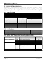
1
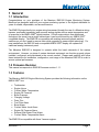
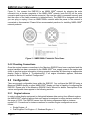
®
EMS100
Engine Monitoring System
User’s Manual
Revision 1.1
Copyright © 2012 Maretron, LLP All Rights Reserved
Maretron, LLP
9014 N. 23rd Ave #10
Phoenix, AZ 85021
http://www.maretron.com
Maretron Manual Part #: M001601
Revision 1.1
Page i
EMS100 User’s Manual
Revision History
Revision
Description
1.0
Original document
1.1
Added information on tachometer connection
Added factory default number of flywheel teeth
Added information on which fields of transmitted PGN’s are populated
Page ii
Revision 1.1
®
Table of Contents
1 General ..............................................................................................................................1 1.1 Introduction ................................................................................................................1 1.2 Firmware Revision .....................................................................................................1 1.3 Features ....................................................................................................................1 1.4 Quick Install ...............................................................................................................2 2 Installation ..........................................................................................................................2 2.1 Unpacking the Box ....................................................................................................2 2.2 Choosing a Mounting Location ..................................................................................2 2.3 Mounting the EMS100 ...............................................................................................3 2.4 Connecting the EMS100............................................................................................3 2.4.1 Connecting to NMEA 2000® Interface ........................................................3 2.4.2 Checking Connections................................................................................4 2.5 Configuration .............................................................................................................4 2.5.1 Engine Instance ..........................................................................................4 2.5.2 Drive Trim Gauge Type ..............................................................................5 2.5.3 Drive Trim Sender Type .............................................................................5 2.5.4 Drive Trim Sender Offset ............................................................................5 2.5.5 Boost Pressure Gauge Type ......................................................................5 2.5.6 Boost Pressure Sender Type .....................................................................5 2.5.7 Boost Pressure Sender Offset ....................................................................5 2.5.8 Oil Pressure Gauge Type ...........................................................................6 2.5.9 Oil Pressure Sender Type ..........................................................................6 2.5.10 Oil Pressure Sender Offset ....................................................................6 2.5.11 Water Temperature Gauge Type ...........................................................6 2.5.12 Water Temperature Sender Type ..........................................................6 2.5.13 Water Temperature Sender Offset .........................................................6 2.5.14 Engine Hours .........................................................................................6 2.5.15 Flywheel Teeth ......................................................................................7 2.5.16 NMEA 2000® PGN Enable/Disable ........................................................7 2.5.17 Restore Factory Defaults .......................................................................7 3 Maintenance ......................................................................................................................7 4 Troubleshooting .................................................................................................................8 5 Technical Specifications................................................................................................... 10 5.1 Specifications .......................................................................................................... 10 5.2 Certifications ............................................................................................................ 10 5.3 NMEA 2000® Parameter Group Numbers (PGNs) .................................................. 10 Technical Support ..................................................................................................................... 11 Installation Template ................................................................................................................ 12 Maretron (2 Year) Limited Warranty ......................................................................................... 13 Revision 1.1
Page iii
EMS100 User’s Manual
Table of Figures
Figure 1 – Mounting the EMS100 .............................................................................................. 3 Figure 2 – NMEA 2000® Connector Face Views ....................................................................... 4 Figure 3 – Mounting Surface Template ................................................................................... 12 Table of Appendices
Appendix A – NMEA 2000® Interfacing.................................................................................... A1
Page iv
Revision 1.1
®
1 General
1.1 Introduction
Congratulations on your purchase of the Maretron EMS100 Engine Monitoring System.
Maretron has designed and built your engine monitoring system to the highest standards for
years of reliable, dependable, and accurate service.
The EMS100 plugs directly into engine wiring harnesses (through the use of a Maretron wiring
harness, purchased separately) and converts analog signals such as water temperature and
oil pressure to the NMEA 2000® digital interface. Critical engine data is then distributed
throughout the vessel over a single cable where it can be monitored by any NMEA 2000®
compatible display. The EMS100 is compatible with existing instrument panels and key
switches so you don’t need to remove them while upgrading to newer digital technology. For
new installations, the EMS100 and a compatible NMEA 2000® display can replace the
traditional analog instrument panel.
The Maretron EMS100 is designed to operate within the harsh demands of the marine
environment. However, no piece of marine electronic equipment can function properly unless
installed, configured, and maintained in the correct manner. Please read carefully and follow
these instructions for installation, configuration, and usage of the Maretron EMS100 in order to
ensure optimal performance.
1.2 Firmware Revision
This manual corresponds to EMS100 firmware revision 1.1.1.
1.3 Features
The Maretron EMS100 Engine Monitoring System provides the following information on the
NMEA 2000® bus.
•
•
•
•
•
•
•
•
•
•
•
•
•
Tachometer
Engine Hours
Coolant Water Temperature
Engine Oil Pressure
Boost Pressure
Charging Voltage
Drive Trim
Fuel Filter Alarm
Boost Alarm
Coolant Water Level Alarm
Engine Oil Pressure Alarm
Exhaust (Salt Water Flow) Alarm
Coolant Water Temperature Alarm
The EMS100 is compatible with these Yanmar engines:
Revision 1.1
Page 1
EMS100 User’s Manual
•
•
•
•
•
•
GM Series
YM Series
JH Series
LH Series
LP Series
LY Series
The EMS100 has the following additional features:
• Waterproof Enclosure and Cable System
• Connects to Analog or Digital tachometers
• Can Work With or Without Existing Analog Gauges
1.4 Quick Install
Installing the Maretron EMS100 Engine Monitoring System involves the following five steps.
Please refer to the individual sections for additional details.
1.
2.
3.
4.
5.
Unpack the Box (Section 2.1)
Choose a Mounting Location (Section 2.2)
Mount the EMS100 Engine Monitoring System (Section 2.3)
Connect the EMS100 Engine Monitoring System (Section 2.4)
Configure the EMS100 Engine Monitoring System (Section 2.5)
2 Installation
2.1 Unpacking the Box
When unpacking the box containing the Maretron EMS100, you should find the following items.
•
•
•
1 – EMS100 Engine Monitoring System
1 – EMS100 User’s Manual
1 – Warranty Registration Card
If any of these items are missing or damaged, please contact Maretron.
2.2 Choosing a Mounting Location
The EMS100 is mounted between the engine and the NMEA 2000® network. Please consider
the following when choosing a mounting location.
1. The EMS100 is waterproof, so it can be mounted in a damp or dry location.
2. The orientation is not important, so the EMS100 can be mounted on a horizontal deck,
vertical bulkhead, or even upside down if desired.
3. The EMS100 is temperature rated to 55°C (130°F), so it should be mounted away from
engines or engine rooms where the operating temperature exceeds the specified limit.
Page 2
Revision 1.1
®
2.3 Mounting the EMS100
Attach the Maretron EMS100 securely to the vessel using bolts or screws (not included) as
shown in Figure 1 below.
Figure 1 – Mounting the EMS100
2.4 Connecting the EMS100
You connect the EMS100 using a Maretron wiring harness (available separately) which is
designed for a particular type of engine. One end of the Maretron wiring harness has two 12pin Deutsch connectors which plug into the two connectors on the end of the EMS100 product
enclosure. These connectors are keyed differently, so there is no danger of plugging these in
incorrectly.
2.4.1 Connecting to NMEA 2000® Interface
The Maretron EMS100 provides a connection to an NMEA 2000® interface through a five pin
male connector located on the Maretron wiring harness, which is purchased separately (see
Revision 1.1
Page 3
EMS100 User’s Manual
Figure 2). You connect the EMS100 to an NMEA 2000® network by plugging the male
connector into a female receptacle of the NMEA 2000® network (note the key on the male
connector and keyway on the female connector). Be sure the cable is connected securely and
that the collar on the cable connector is tightened firmly. The EMS100 is designed such that
you can plug or unplug it from an NMEA 2000® network while the power to the network is
connected or disconnected. Please follow recommended practices for installing NMEA 2000®
network products.
Figure 2 – NMEA 2000® Connector Face Views
2.4.2 Checking Connections
Once the engine harness connections to the Maretron EMS100 have been completed and the
engine harness has been connected to the NMEA 2000® bus, supply power to the engine and
check to see that engine information is being properly transmitted by observing an appropriate
display. Refer to Section 4, “Troubleshooting”, if no engine information appears, otherwise
proceed to Section 2.5 entitled “Configuration”.
2.5 Configuration
There are several configurable items within the EMS100. You configure the EMS100 using a
Maretron DSM250 display or other NMEA 2000® display unit that is capable of configuring the
EMS100. Please refer to the Maretron DSM250 User’s Manual for details. Descriptions of the
various configurable items appear in the following sections.
2.5.1 Engine Instance
In order to allow display equipment to distinguish between data coming from different engines,
the NMEA 2000® network requires that each engine be assigned a unique instance number in
the range of 0-252. The EMS100 comes from the factory programmed with an instance
number of 0. Conventions for instance numbers for common engine configurations are as
follows:
• Single Engine = 0
• Dual Engines: Port Engine = 0, Starboard Engine = 1
Page 4
Revision 1.1
®
•
Triple Engines: Port Engine = 0, Starboard Engine = 1, Center Engine =2
2.5.2 Drive Trim Gauge Type
The EMS100 comes from the factory preprogrammed with the characteristics of drive trim
gauge types for supported engines. If the EMS100 is used with an analog drive trim gauge,
you must select the correct type of gauge for this setting in order for the data to be displayed
correctly. If you have no drive trim gauge present, select the “No Gauge” option for this
setting.
2.5.3 Drive Trim Sender Type
The EMS100 comes from the factory preprogrammed with the characteristics of drive trim
senders for supported engines. If the engine to which you are connecting the EMS100 has a
drive trim sender, you must select the correct type of drive trim sender for this setting in order
for the data to be displayed correctly. If you have no drive trim sender present, select the
“Disabled” option for this setting.
2.5.4 Drive Trim Sender Offset
Often, the characteristics of individual drive trim senders vary from their specified values. This
setting allows you to apply an offset to the resistance value of the drive trim sender in order to
allow you to bring the digital value reported by the EMS100 into agreement with that displayed
by the analog gauge.
2.5.5 Boost Pressure Gauge Type
The EMS100 comes from the factory preprogrammed with the characteristics of boost
pressure gauge types for supported engines. If the EMS100 is used with an analog boost
pressure gauge, you must select the correct type of gauge for this setting in order for the data
to be displayed correctly. If you have no boost pressure gauge present, select the “No Gauge”
option for this setting.
2.5.6 Boost Pressure Sender Type
The EMS100 comes from the factory preprogrammed with the characteristics of boost
pressure senders for supported engines. If the engine to which you are connecting the
EMS100 has a boost pressure sender, you must select the correct type of boost pressure
sender for this setting in order for the data to be displayed correctly. If you have no boost
pressure sender present, select the “Disabled” option for this setting.
2.5.7 Boost Pressure Sender Offset
Often, the characteristics of individual boost pressure senders vary from their specified values.
This setting allows you to apply an offset to the resistance value of the boost pressure sender
in order to allow you to bring the digital value reported by the EMS100 into agreement with that
displayed by the analog gauge.
Revision 1.1
Page 5
EMS100 User’s Manual
2.5.8 Oil Pressure Gauge Type
The EMS100 comes from the factory preprogrammed with the characteristics of oil pressure
gauge types for supported engines. If the EMS100 is used with an analog oil pressure gauge,
you must select the correct type of gauge for this setting in order for the data to be displayed
correctly. If you have no oil pressure gauge present, select the “No Gauge” option for this
setting.
2.5.9 Oil Pressure Sender Type
The EMS100 comes from the factory preprogrammed with the characteristics of oil pressure
senders for supported engines. If the engine to which you are connecting the EMS100 has a
oil pressure sender, you must select the correct type of oil pressure sender for this setting in
order for the data to be displayed correctly. If you have no oil pressure sender present, select
the “Disabled” option for this setting.
2.5.10 Oil Pressure Sender Offset
Often, the characteristics of individual oil pressure senders vary from their specified values.
This setting allows you to apply an offset to the resistance value of the oil pressure sender in
order to allow you to bring the digital value reported by the EMS100 into agreement with that
displayed by the analog gauge.
2.5.11 Water Temperature Gauge Type
The EMS100 comes from the factory preprogrammed with the characteristics of water
temperature gauge types for supported engines. If the EMS100 is used with an analog water
temperature gauge, you must select the correct type of gauge for this setting in order for the
data to be displayed correctly. If you have no water temperature gauge present, select the “No
Gauge” option for this setting.
2.5.12 Water Temperature Sender Type
The EMS100 comes from the factory preprogrammed with the characteristics of water
temperature senders for supported engines. If the engine to which you are connecting the
EMS100 has a water temperature sender, you must select the correct type of water
temperature sender for this setting in order for the data to be displayed correctly. If you have
no water temperature sender present, select the “Disabled” option for this setting.
2.5.13 Water Temperature Sender Offset
Often, the characteristics of individual water temperature senders vary from their specified
values. This setting allows you to apply an offset to the resistance value of the water
temperature sender in order to allow you to bring the digital value reported by the EMS100 into
agreement with that displayed by the analog gauge.
2.5.14 Engine Hours
The EMS100 reports engine hours based on how long the EMS100 has been powered from
the engine. The EMS100 comes from the factory preprogrammed with an engine hours
reading of 0 hours. If you are installing the EMS100 on an engine that has been in service, or
Page 6
Revision 1.1
®
if you have overhauled an engine, you can use this setting to preset the engine hours reading
to the desired value.
2.5.15 Flywheel Teeth
The EMS100 needs to know the number of flywheel teeth on the engine (or the number of
alternator pulses per revolution) in order to correctly calculate engine RPM. Use this setting to
program the EMS100 with the number of flywheel teeth or alternator pulses per revolution for
the engine the EMS100 is connected to. The factory default value of this parameter is 129.
2.5.16 NMEA 2000® PGN Enable/Disable
The EMS100 is capable of transmitting several different kinds of NMEA 2000® messages (or
PGNs) associated with engines. You can use this setting to enable or disable transmission of
each of these message types.
2.5.17 Restore Factory Defaults
This setting will cause all user-programmable settings on the EMS100 to be restored to the
values that were in the EMS100 when it was shipped from the factory.
3 Maintenance
Regular maintenance is important to ensure continued proper operation of the Maretron
EMS100. Perform the following tasks periodically:
•
•
•
Clean the unit with a soft cloth. Do not use chemical cleaners as they may remove
paint or markings or may corrode the EMS100 enclosure or seals.
Ensure that the unit is mounted securely and cannot be moved relative to the mounting
surface. If the unit is loose, tighten the mounting screws.
Check the security of the connections to the engine wiring harness and re-seat or
tighten if necessary.
Revision 1.1
Page 7
EMS100 User’s Manual
4 Troubleshooting
If you notice unexpected operation of the Maretron EMS100, follow the troubleshooting
procedures in this section to remedy simple problems. If these steps do not solve your
problem, please contact Maretron Technical Support (refer to Section 0 for contact
information).
Symptom
No engine data visible
on NMEA 2000®
network.
Troubleshooting Procedure
Ensure that the NMEA 2000® network is operational by observing
displays. You should see information from components besides the
ones attached to the EMS100 which verifies an operational NMEA
2000® network. If you don’t see data, try disconnecting the NMEA
2000 connection you made to the EMS100 as something may
have been connected incorrectly.
Ensure that the Maretron wiring harness is securely connected
both to the EMS100 and to the existing engine wiring harness as
directed in the instructions supplied with the Maretron wiring
harness.
Once you are sure that the NMEA 2000 network is operational with
a connected EMS100, ensure that the NMEA 2000® connector on
the Maretron wiring harness is securely connected to the NMEA
2000® network.
Ensure that the ignition switch for engine is turned on. The
EMS100 draws the majority of its power from the engine power
connection.
Ensure that the EMS100 is programmed with an appropriate
engine NMEA 2000 instance as described in Section 2.5.1.
Incorrect Engine Data
Incorrect Tachometer
Readings
Ensure that all NMEA 2000® messages are enabled (see Section
2.5.16 for details).
Ensure that the settings for gauge type, sender type, and number
of flywheel teeth are programmed appropriately.
Check the values of sender offset programmed into the EMS100.
Check the adjustment of the tachometer sensor on the engine.
Once the EMS100 is connected, you may need to adjust the
spacing between the sensor and the flywheel teeth.
Warning: There are no user-serviceable components inside the Maretron EMS100.
Opening the EMS100 will expose the sensitive electronic components to adverse
environmental conditions that may render the unit inoperative. Please do not open the
Page 8
Revision 1.1
®
EMS100, as this will automatically void the warranty. If service is required, please return
the unit to an authorized Maretron service location.
Revision 1.1
Page 9
EMS100 User’s Manual
5 Technical Specifications
As Maretron is constantly improving its products, all specifications are subject to change
without notice. Maretron products are designed to be accurate and reliable; however, they
should be used only as aids to navigation and not as a replacement for traditional navigation
aids and techniques.
5.1 Specifications
Parameter
Tachometer
Engine Hours
Oil Pressure
Coolant Water Temperature
Boost Pressure
Drive Trim Angle
Charging Voltage
Lube Oil Filter Alarm
Boost Pressure Alarm
Coolant Water Temperature Alarm
Oil Pressure Alarm
Exhaust (Salt Water Flow) Alarm
Clutch Oil Pressure Alarm
Diesel Preheat Alarm
Type
Analog/Digital Input
Logged with Key On
Analog Input
Analog Input
Analog Input
Analog Input
Alarm/Switch Input
Alarm/Switch Input
Alarm/Switch Input
Alarm/Switch Input
Alarm/Switch Input
Alarm/Switch Input
Alarm/Switch Input
Alarm/Switch Input
Comment
Configurable by # of Teeth
Stored Indefinitely in Non-Volatile Memory
Sensor Voltage Monitor/Sensitize
Sensor Voltage Monitor/Sensitize
Sensor Voltage Monitor/Sensitize
Sensor Voltage Monitor/Sensitize
5.2 Certifications
Parameter
NMEA 2000®
Maritime Navigation and Radiocommunication Equipment & Systems
FCC and CE Mark
Comment
Level A
IEC 60945
Electromagnetic Compatibility
5.3 NMEA 2000® Parameter Group Numbers (PGNs)
Description
Periodic Data PGNs
Response to Requested PGNs
Protocol PGNs
Maretron Proprietary PGNs
Page 10
PGN #
127488
127489
126464
126996
126998
059392
059904
060416
060160
060928
065240
126208
128720
PGN Name
Engine Parameters, Rapid Update
Engine Parameters, Dynamic
PGN List (Transmit and Receive)
Product Information
Configuration Information
ISO Acknowledge
ISO Request
ISO Transport Protocol, Connection
Management
ISO Transport Protocol, Data Transfer
ISO Address Claim
ISO Address Command
NMEA
Configuration
Default Rate
10 times/second
1 time/second
N/A
N/A
N/A
N/A
N/A
N/A
N/A
N/A
N/A
N/A
Revision 1.1
®
Electrical
Parameter
Operating Voltage
Power Consumption
Load Equivalence Number (LEN)
Reverse Battery Protection
Load Dump Protection
Value
9 to 16 Volts
<150mA
1
Yes
Yes
Comment
DC Voltage
From Battery
NMEA 2000® Spec. (1LEN = 50 mA)
Indefinitely
Energy Rated per SAE J1113
Mechanical
Parameter
Value
5” x 4.5” x 1.25”
12 oz.
Size
Weight
Comment
Excluding Wiring Harness
Excluding Wiring Harness
Environmental
Parameter
IEC 60954 Classification
Degree of Protection
Operating Temperature
Storage Temperature
Relative Humidity
Vibration
Rain and Spray
Solar Radiation
Corrosion (Salt Mist)
Electromagnetic Emission
Electromagnetic Immunity
Safety Precautions
Value
Exposed
IP68
-25°C to 55°C
-40°C to 70°C
93%RH @40° per IEC60945-8.2
2-13.2Hz @ ±1mm, 13.2-100Hz @ 7m/s2 per IEC 60945-8.7
12.5mm Nozzle @ 100liters/min from 3m for 30min per IEC 60945-8.8
Ultraviolet B, A, Visible, and Infrared per IEC 60945-8.10
4 times 7days @ 40°C, 95%RH after 2 hour Salt Spray Per IEC 60945-8.12
Conducted and Radiated Emission per IEC 60945-9
Conducted, Radiated, Supply, and ESD per IEC 60945-10
Dangerous Voltage, Electromagnetic Radio Frequency per IEC 60945-12
Technical Support
If you require technical support for Maretron products, you can reach us in any of the following
ways:
Telephone:
Fax:
E-mail:
World Wide Web:
Mail:
Revision 1.1
1-866-550-9100
1-602-861-1777
[email protected]
http://www.maretron.com
Maretron, LLP
Attn: Technical Support
9014 N. 23rd Ave Suite 10
Phoenix, AZ 85021 USA
Page 11
EMS100 User’s Manual
Installation Template
Please check the dimensions before using the following diagram as a template for drilling the
mounting holes because the printing process may have distorted the dimensions.
4.0”
Figure 3 – Mounting Surface Template
Page 12
Revision 1.1
®
Maretron (2 Year) Limited Warranty
Maretron warrants the EMS100 to be free from defects in materials and workmanship for two (2) years from the
date of original purchase. If within the applicable period any such products shall be proved to Maretron’s
satisfaction to fail to meet the above limited warranty, such products shall be repaired or replaced at Maretron’s
option. Purchaser's exclusive remedy and Maretron’s sole obligation hereunder, provided product is returned
pursuant to the return requirements below, shall be limited to the repair or replacement, at Maretron’s option, of
any product not meeting the above limited warranty and which is returned to Maretron; or if Maretron is unable to
deliver a replacement that is free from defects in materials or workmanship, Purchaser’s payment for such
product will be refunded. Maretron assumes no liability whatsoever for expenses of removing any defective
product or part or for installing the repaired product or part or a replacement therefore or for any loss or damage
to equipment in connection with which Maretron’s products or parts shall be used. With respect to products not
manufactured by Maretron, Maretron’s warranty obligation shall in all respects conform to and be limited to the
warranty actually extended to Maretron by its supplier. The foregoing warranties shall not apply with respect to
products subjected to negligence, misuse, misapplication, accident, damages by circumstances beyond
Maretron’s control, to improper installation, operation, maintenance, or storage, or to other than normal use or
service.
THE FOREGOING WARRANTIES ARE EXPRESSLY IN LIEU OF AND EXCLUDES ALL OTHER EXPRESS OR
IMPLIED WARRANTIES, INCLUDING BUT NOT LIMITED TO THE IMPLIED WARRANTIES OF
MERCHANTABILITY AND OF FITNESS FOR A PARTICULAR PURPOSE.
Statements made by any person, including representatives of Maretron, which are inconsistent or in conflict with
the terms of this Limited Warranty, shall not be binding upon Maretron unless reduced to writing and approved by
an officer of Maretron.
IN NO CASE WILL MARETRON BE LIABLE FOR INCIDENTAL OR CONSEQUENTIAL DAMAGES, DAMAGES
FOR LOSS OF USE, LOSS OF ANTICIPATED PROFITS OR SAVINGS, OR ANY OTHER LOSS INCURRED
BECAUSE OF INTERRUPTION OF SERVICE. IN NO EVENT SHALL MARETRON’S AGGREGATE LIABILITY
EXCEED THE PURCHASE PRICE OF THE PRODUCT(S) INVOLVED. MARETRON SHALL NOT BE SUBJECT
TO ANY OTHER OBLIGATIONS OR LIABILITIES, WHETHER ARISING OUT OF BREACH OF CONTRACT OR
WARRANTY, TORT (INCLUDING NEGLIGENCE), OR OTHER THEORIES OF LAW WITH RESPECT TO
PRODUCTS SOLD OR SERVICES RENDERED BY MARETRON, OR ANY UNDERTAKINGS, ACTS OR
OMISSIONS RELATING THERETO.
Maretron does not warrant that the functions contained in any software programs or products will meet
purchaser’s requirements or that the operation of the software programs or products will be uninterrupted or error
free. Purchaser assumes responsibility for the selection of the software programs or products to achieve the
intended results, and for the installation, use and results obtained from said programs or products. No
specifications, samples, descriptions, or illustrations provided Maretron to Purchaser, whether directly, in trade
literature, brochures or other documentation shall be construed as warranties of any kind, and any failure to conform
with such specifications, samples, descriptions, or illustrations shall not constitute any breach of Maretron’s limited
warranty.
Warranty Return Procedure:
To apply for warranty claims, contact Maretron or one of its dealers to describe the problem and determine the
appropriate course of action. If a return is necessary, place the product in its original packaging together with
proof of purchase and send to an Authorized Maretron Service Location. You are responsible for all shipping and
insurance charges. Maretron will return the replaced or repaired product with all shipping and handling prepaid
except for requests requiring expedited shipping (i.e. overnight shipments). Failure to follow this warranty return
procedure could result in the product’s warranty becoming null and void.
Maretron reserves the right to modify or replace, at its sole discretion, without prior notification, the warranty listed
above. To obtain a copy of the then current warranty policy, please go to the following web page:
http://www.maretron.com/company/warranty.php
Revision 1.1
Page 13
EMS100 User’s Manual
This page intentionally left blank
Page 14
Revision 1.1
®
Appendix A – NMEA 2000® Interfacing
Note: For integer values, the most positive three values are reserved; e.g., for 8-bit unsigned integers,
the values 0xFD, 0xFE, 0xFF are reserved, and for 8-bit signed integers, the values 0x7D, 0x7E, 0x7F
are reserved. The most positive value (0xFF and 0x7F, respectively, for the 8-bit examples) represents
Data Not Available.
EMS100 NMEA 2000® Periodic Data Transmitted PGNs
PGN 127488 – Engine Parameters, Rapid Update
The EMS100 uses this PGN to transmit rapidly changing engine data.
Field 1: Engine Instance – (8-bit unsigned integer) This field indicates the particular engine
for which this data applies. A single engine will have an instance of 0. Engines in
multi-engine boats will be numbered starting at 0 at the bow of the boat incrementing
to n going in towards the stern of the boat. For engines at the same distance from the
bow are stern, the engines are numbered starting from the port side and proceeding
towards the starboard side.
2: Engine Speed – (16-bit unsigned integer) This field indicates the rotational speed of
the engine in units of ¼ RPM.
3: Engine Boost Pressure – (16-bit unsigned integer) This field indicates the
turbocharger boost pressure in units of 100 Pa.
4: Engine tilt/trim – (8-bit signed integer) This field indicates the tilt or trim (positive or
negative) of the engine in units of 1 percent.
5: Reserved – (16 bits) This field is reserved by NMEA; therefore, the EMS100 sets all
bits to a logic 1.
PGN 127489 – Engine Parameters, Dynamic
The EMS100 uses this PGN to transmit more slowly changing engine data.
Field 1: Engine Instance – (8-bit unsigned integer) This field indicates the particular engine
for which this data applies. A single engine will have an instance of 0. Engines in
multi-engine boats will be numbered starting at 0 at the bow of the boat incrementing
to n going in towards the stern of the boat. For engines at the same distance from the
bow are stern, the engines are numbered starting from the port side and proceeding
towards the starboard side.
2: Engine Oil Pressure – (16-bit unsigned integer) This field indicates the oil pressure of
the engine in units of 100 Pa.
3: Engine Oil Temperature – (16-bit unsigned integer) This field indicates the oil
temperature of the engine in units of 0.1°K. The EMS100 does not provide a value for
this field.
4: Engine Temperature – (16-bit unsigned integer) This field indicates the temperature
of the engine coolant in units of 0.1°K.
5: Alternator Potential – (16-bit signed integer) This field indicates the alternator voltage
in units of 0.01V.
Revision 1.1
Page A1
EMS100 User’s Manual
6: Fuel Rate – (16-bit signed integer) This field indicates the fuel consumption rate of
the engine in units of 0.0001 cubic meters / hour. The EMS100 does not provide a
value for this field.
7: Total Engine Hours – (32-bit unsigned integer) This field indicates the cumulative
runtime of the engine in units of 1 second.
8: Engine Coolant Pressure – (16-bit unsigned integer) This field indicates the pressure
of the engine coolant in units of 100 Pa. The EMS100 does not provide a value for
this field.
9: Fuel Pressure – (16-bit unsigned integer) This field indicates the pressure of the
engine fuel in units of 1000 Pa. The EMS100 does not provide a value for this field.
10: Reserved – (8 bits) This field is reserved by NMEA; therefore, the EMS100 sets all
bits to a logic 1.
11: Engine Discrete Status 1 – (16 bits) This field indicates warning conditions of the
engine with the following bit assignments (value of 1 indicates warning present):
Bit 0: Check Engine - The EMS100 always transmits a value of 0 for this field.
Bit 1: Over Temperature
Bit 2: Low Oil Pressure
Bit 3: Low Oil Level - The EMS100 always transmits a value of 0 for this field.
Bit 4: Low Fuel Pressure - The EMS100 always transmits a value of 0 for this
field.
Bit 5: Low System Voltage - The EMS100 always transmits a value of 0 for this
field.
Bit 6: Low Coolant Level
Bit 7: Water Flow
Bit 8: Water in Fuel
Bit 9: Charge Indicator
Bit 10: Preheat Indicator
Bit 11: High Boost Pressure
Bit 12: Rev Limit Exceeded - The EMS100 always transmits a value of 0 for this
field.
Bit 13: EGR System - The EMS100 always transmits a value of 0 for this field.
Bit 14: Throttle Position Sensor - The EMS100 always transmits a value of 0 for
this field.
Bit 15: Emergency Stop Mode
12: Engine Discrete Status 2 – (16 bits) This field indicates warning conditions of the
engine with the following bit assignments (value of 1 indicates warning present):
Bit 0: Warning Level 1 - The EMS100 always transmits a value of 0 for this field.
Bit 1: Warning Level 2 - The EMS100 always transmits a value of 0 for this field.
Bit 2: Power Reduction - The EMS100 always transmits a value of 0 for this
field.
Bit 3: Maintenance Needed - The EMS100 always transmits a value of 0 for this
field.
Bit 4: Engine Comm Error - The EMS100 always transmits a value of 0 for this
field.
Bit 5: Sub or Secondary Throttle - The EMS100 always transmits a value of 0 for
this field.
Page A2
Revision 1.1
®
Bit 6: Neutral Start Protect - The EMS100 always transmits a value of 0 for this
field.
Bit 7: Engine Shutting Down - The EMS100 always transmits a value of 0 for this
field.
Bit 8-15: These bits are reserved and should be masked when read
13: Percent Engine Load – (8-bit signed integer) This field indicates the percent load of
the engine in units of 1 percent. The EMS100 does not provide a value for this field.
14: Percent Engine Torque – (8-bit signed integer) This field indicates the percent torque
of the engine in units of 1 percent. The EMS100 does not provide a value for this
field.
Revision 1.1
Page A3