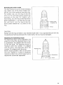
1
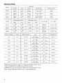
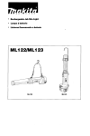
Cordless Percussion=DriverDrill
Equipped with Electric Brake
INSTRUCTION MANUAL
DZ
DWA
Nt-Cd 2 0 AH
DWD N I - M H ~ ~ H
DWF NI-MH 3 o AH-
-
-
SPECIFICATIONS
Concrete
Steel
Wood
Wood screw
Machine screw
13 mm
f 1/2 ")
13 m m
( 1 /2 ")
30 m m
(1-3/16"1
6 mm x 75 m m
(1/4" x 3")
6 mm
(1/4" )
8413D
38"
No load speed (RPM)
Model
8413D
8433D
84431)
I
I
I
1
High
0-1'300
/min.
o~,.,!,;~
o
~
I
I
I
"
lOmmx90mm
(3/8" x 3-1/2")
0-400
/min.
'it,
;
1
I
I
High
0-19,500
0 - 19.500
0-21,000
~
I
I
I
1
Overall length
Low
0-6,000
0 -6,000
0-6,750
1
1
1
;zlxy
-,/2,,)
267mm
fiylxm)
7 2 V - 144V
*
Manufacturer reserves the right t o change specifications without notice
Note Specifications may differ from country to country
WARNING For your personal safety, READ and understand before using
SAVE THESE INSTRUCTIONS FOR FUTURE REFERENCE
2
I 1/4 " )
Blows per minute
Low
o/~Tnpnso
I
6 mm
11/4 )
Net weight
I
I
1
2.3kg15.1 Ibs)
2 4 kg 15 3 Ibs)
2.6 kg15.7 lbsl
GENERAL SAFETY RULES
U’A(l(’J1
(For All Battery Operated Tools)
WARNING! Read and understand all instructions. Failure
to follow all instructions listed below, may result in electric
shock, fire and/or serious personal injury.
SAVE THESE INSTRUCTIONS
Work A r e a
1. Keep your work area clean and well lit. Cluttered benches and dark areas invite
accidents.
2. D o not operate power tools in explosive atmospheres, such as in the presence
of flammable liquids, gases, or dust. Power tools create sparks which may
ignite the dust or fumes.
3.Keep bystanders, children, and visitors away while operating a power tool.
Distractions can cause you t o lose control.
Electrical Safety
4. A battery operated t o o l with integral batteries or a separate battery pack
must be recharged only with the specified charger for the battery. A charger
that may be suitable for one type of battery may create a risk of fire w h e n
used with another battery.
5. Use battery operated t o o l only with specifically designated battery pack.
Use of any other batteries may create a risk of fire.
Personal S a f e t y
6. Stay alert, watch what you are doing, and use common sense when operating
a power tool. D o n o t use tool while tired or under the influence o f drugs,
alcohol, or medication. A moment of inattention while operating power tools
may result in serious personal injury.
7. Dress properly. D o not wear loose clothing or jewelry. Contain long hair. Keep
your hair, clothing, and gloves away from moving parts. Loose clothes, jewelry.
or long hair can be caught in moving parts.
8. Avoid accidental starting. Be sure s w i t c h is in the locked or off position before
inserting battery pack. Carrying tools w i t h your finger o n t h e switch or
inserting the battery pack into a tool with the switch o n invites accidents.
9.Remove adjusting keys or wrenches before turning the tool on. A wrench
or a key that is left attached t o a rotating part of the tool may result in personal
injury.
10. Do not overreach. Keep proper footing and balance at all times. Proper footing
and balance enable better control of t h e tool in unexpected situations.
1 1 , Use safety equipment. Always wear eye protection. Dust mask, non-skid
safety shoes, hard hat, or hearing protection must be used for appropriate
conditions.
3
Tool U s e a n d C a r e
12. Use clamps or other practical way t o secure and support the workpiece t o
a stable platform. Holding the work by hand or against your body is unstable
and may lead t o loss of control.
13.Do not force tool. Use the correct tool for your application. The correct tool
will do t h e job better and safer at the rate for which it is designed.
14. Do n o t use t o o l i f s w i t c h does n o t t u r n it o n or off. A tool that cannot be
controlled with the s w i t c h is dangerous and must be repaired.
15. Disconnect battery pack from tool or place the s w i t c h in the locked or o f f
position before making any adjustments, changing accessories, or storing
the tool. Such preventive safety measures reduce the risk of starting the tool
acc id e nta IIy.
16. Store idle tools out of reach of children and other untrained persons. Tools
are dangerous in the hands of untrained users.
17. When battery pack is n o t in use, keep it away f r o m other metal objects like:
paper clips, coins, keys, nails, screws, or other small metal objects that can
make a connection f r o m one terminal t o another. Shorting the battery
terminals together may cause sparks, burns, or a fire.
18. Maintain tools with care. Keep cutting tools sharp and clean. Properly
maintained tools with sharp cutting edge are less likely t o bind and are easier
t o control.
19. Check for misalignment or binding of moving parts, breakage of parts, and
any other condition t h a t may affect the tool's operation. If damaged, have
the t o o l serviced before using. Many accidents are caused b y poorly
maintained tools.
20. Use only accessories t h a t are recommended by the manufacturer for your
model. Accessories that may be suitable for one tool may create a risk of injury
when used o n another tool.
Service
21. Tool service m u s t be performed only by qualified repair personnel. Service
or maintenance performed by unqualified personnel may result in a risk of injury.
22. When servicing a tool, use only identical replacement ,parts. Follow
instructions in the Maintenance section of this manual. Use of unauthorized
parts or failure t o follow Maintenance Instructions may create a risk of shock
or injury.
4
Specific Safety Rules
1. Hold tool by insulated gripping surfaces w h e n performing an operation where
the cutting tool may contact hidden wiring. Contact w i t h a "live" wire will
also make exposed metal parts of the tool "live" and shock the operator.
2. Be aware that this tool is always in an operating condition, because it does
n o t have t o be plugged i n t o an electrical outlet.
3. Always be sure you have a f i r m footing.
Be sure no one is below w h e n using the tool in high locations.
4. Hold the tool firmly.
5. Keep hands away from rotating parts.
6. Do not leave the tool running. Operate the tool only w h e n hand-held.
7. Do not touch the drill bit or the workpiece immediately after operation; they
may be extremely hot and could burn your skin.
SYMBOLS
The followings show the symbols used for tool.
v
n,
....................................
volts
....................................
direct current
....................................
no load speed
.../min
...................................
b
....................................
revolutions or reciprocation per minute
number of blow
5
IMPORTANT SAFETY INSTRUCTIONS
FOR CHARGER &
BATTERY CARTRIDGE
I. SAVE THESE INSTRUCTIONS - This manual
Length of Cord (Feet)
AWG Size of Cord
6
25
18
50
100
150
18
18
16
ADDITIONAL SAFETY RULES
FOR CHARGER & BATTERY CARTRIDGE
USCUOl 1
1 . Do not charge Battery Cartridge w h e n temperature is BELOW 10°C (5OOF)
or ABOVE 4OoC (104OF).
2. Do not attempt t o use a step-up transformer, an engine generator or DC power
receptacle.
3. Do not allow anything t o cover or clog t h e charger vents.
4. Always cover the battery terminals with t h e battery cover w h e n the battery
cartridge is not used.
5. A battery short can cause a large current flow, overheating, possible burns
and even a breakdown.
(1) Do n o t touch the terminals with any conductive material.
( 2 )Avoid storing battery cartridge in a container with other metal objects such
as nails, coins, etc.
( 3 )Do not expose battery cartridge t o water or rain.
6. Do not store the tool and Battery Cartridge in locations where t h e temperature may reach or exceed 5OoC (122OF).
7 . Do n o t incinerate t h e Battery Cartridge even i f it i s severely damaged or i s
completely worn out. The battery cartridge can explode in a fire.
SAVE THESE INSTRUCTIONS.
7
FUNCTIONAL DESCRIPTION
Installing or removing battery cartridge
Always switch off the tool before insertion or removal of the battery cartridge
To remove the battery cartridge, withdraw it from the tool while pressing the
buttons on both sides of the cartridge
*To insert the battery cartridge, align the
tongue on the battery cartridge with the
groove in the housing and slip it into
place Always insert it all the way until it
locks in place with a little click If not, it
may accidentally fall out of the tool, causing injury to you or someone around you
* D o not use force when inserting the battery cartridge. If the cartridge does not slide in
easily, it is not being inserted correctly
Charging
*Your new battery cartridge is not charged
You will need to charge it before use Use
the high capacity battery charger Model
DC1411 (for 8413D and 8433D) / DC1801
(for 8443D) to charge the battery cartridge
Battery cartridge
Charging light
Plug the high capacity battery charger into
the proper A C voltage source The
charging light will flash in green color
*Insert the battery cartridge so that the
plus and minus terminals on the battery
cartridge are on the same sides as their respective markings on the high capacity battery
charger. Insert the cartridge fully into the port so that it rests on the charger port floor.
When the battery cartridge is inserted, the charging light color will change from green to
red and charging will begin. The charging light will remain lit steadily during charging.
When the charging light color changes from red to green, the charging cycle is complete
and the charger will switch into its "trickle charge (maintenance charge)" mode. The
charging time is approximately one hour.
*After charging, unplug the charger from the power source
CAUTION:
*The high capacity battery charger Model DC1411 / DC1801 is for charging Makita battery
cartridge. Never use it for other purposes or for other manufacturer's batteries.
When you charge a new battery cartridge or a battery cartridge which has not been used
for a long period of time, it may not accept a full charge This is a normal condition and
does not indicate a problem. You can recharge the battery cartridge fully after discharging
it completely and recharging a couple of times.
8
If you charge a battery cartridge from a just-operated tool or a battery cartridge which has
been left in a location exposed to direct sunlight or heat for a long time, the charging light
may flash in red color If this occurs, wait for a while Charging will begin after the battery
cartridge cools The battery cartridge will cool faster if you remove the battery cartridge
from the high capacity battery charger
If the charging light flashes alternately in green and red color, a problem exists and charging is not possible The terminals on the charger or battery cartridge are clogged with
dust or the battery cartridge IS worn out or damaged
Trickle charge (Maintenance charge)
If you leave the battery cartridge in the charger to prevent spontaneous discharging after
full charge, the charger will switch into its "trickle charge (maintenance charge)" mode and
keep the battery cartridge fresh and fully charged.
Tips for maintaining maximum battery life
1. Charge the battery cartridge before completely discharged.
Always stop tool operation and charge the battery cartridge when you notice less tool
power.
2. Never recharge a fully charged battery cartridge.
Overcharging shortens the battery service life.
3. Charge the battery cartridge with room temperature at 10°C - 40°C (50°F - 104°F).
Let a hot battery cartridge cool down before charging it.
Switch action
CAUTION
Before inserting the battery cartridge into the tool, always check to see that the switch
trigger actuates properly and returns to the "OFF" position when released
To start the tool, simply pull the trigger
Tool speed is increased by increasing pressure on the trigger Release the trigger to
stop
9
Reversing switch action
CAUTION
*Always check the direction of rotation before operation
*Use the reversing switch only after the tool comes to a complete stop Changing the
direction of rotation before the tool stops may damage the tool
*When not operating the tool, always set the reversing switch lever to the neutral position
This tool has a reversing switch to change
the direction of rotation Depress the
reversing switch lever from the A side for
clockwise rotation or from the B side for
counterclockwise rotation When the switch
lever is in the neutral position, the switch
trigger cannot be pulled
Reversing switch lever
Clockwise
Speed change
To change the speed, first switch off the
tool and then slide the speed change lever
to the "11" side for high speed or " I " side
for low speed Be sure that the speed
change lever is set to the correct position
before operation Use the right speed for
your job
- 1
Counterclockwise
I
1
t
t
Low speed
High speed
- Speed change
lever
CAUTION:
*Always set the speed change lever fully to the correct position. If you operate the tool
with the speed change lever positioned half-way between the " I " side and "11" side, the
tool may be damaged.
*Do not use the speed change lever while the tool is running. The tool may be damaged.
10
Selecting the action mode
This tool employs an action mode changing
ring Select one of the three modes suitable for your work needs by using this ring
For rotation only, turn the ring so that the
arrow on the tool body points toward the
anamark on the ring For rotation with
hammering, turn the ring so that the arrow
points toward the +on the ring For rotation with clutch, turn the ring so that the
arrow points toward the m3 mark on the
ring
''
Action mode
changing ring
Arrow
I
CAUTION:
Always set the ring correctly to your desired mode mark. If you operate the tool with the
ring positioned half-way between the mode marks, the tool may be damaged.
Adjusting the fastening torque
The fastening torque can be adjusted in 16
steps by turning the adjusting ring so that
its graduations are aligned with the arrow
on the tool body. The fastening torque is
minimum when the number 1 is aligned
with the arrow, and maximum when the
number 16 is aligned with the arrow.
Before actual operation, drive a trial screw
into your material or a piece of duplicate
material to determine which torque level is
required for a particular application.
A
11
ASSEMBLY
Installing or removing driver bit or drill bit
CAUTI0N :
Always be sure that the tool is switched off and the battery cartridge is removed before
installing or removing the bit.
Turn the sleeve counterclockwise to open
the chuck jaws. Place the bit in the chuck
as far as it will go. Turn the sleeve clockwise to tighten the chuck.
To remove the bit, turn the sleeve counterclockwise.
-
When not using the driver bit, keep it in the
bit holders. Bits 45 mm (1-3/4") long can
be kept there.
Bit
Bit holder
I
Side grip (auxiliary handle)
Always use the side grip to ensure operating safety. Install the side grip so that the
teeth on the grip fit in between the protrusions on the tool barrel.
Then tighten the grip by turning clockwise
at the desired position. It may be swung
360" so as to be secured at any position.
Teeth
Side grip
Loosen
12
Tighten
Adjustable depth rod
The adjustable depth rod is used to drill
holes of uniform depth Loosen the thumb
screw, set to desired position, then tighten
the thumb screw
s
OPERATION
Screwdriving operation
First, turn the action mode changing ring so
that the arrow on the tool body points to
the c . 4 marking Adjust the adjusting ring
to the proper torque level for your work
Then proceed as follows
Place the point of the driver bit in the screw
head and apply pressure to the tool Start
the tool slowly and then increase the speed
gradually Release the trigger as soon as
the clutch cuts in
*When driving wood screws, predrill pilot
holes to make driving easier and to prevent splitting of the workpiece. See the
chart.
Nominal diameter of
'
woodscrewl"l
Recommended size of
pllot hole 1)"
3 1 11/8"1
2 0 - 2 2 15/64'' - 3/32")
3 5 19/64',)
2 3 - 2 5 13/32"
3 8 15/32")
2 5 - 2 8 13/32''- 7/64',)
~
3/32',)
4 5 (1 1/64"J
2 9 - 3 2 (7164" - 1/8"J
4 8 (3/16")
3 1 - 3 4 (1/8" - 9/64")
5 1 113/64")
3 3 - 3 6 1,IlE'' - 9/61")
5 5 17/32")
3 7 - 3 9 (914'' 5/32")
5 8 17/32")
4 0-4
6 1 I 15/64 "1
4 2 - 4 4 11 1/64" - 11/64")
~
2 15/32'' - 11/64")
*If the tool is operated continuously until the battery cartridge has discharged, allow the
tool to rest for 15 minutes before proceeding with a fresh battery.
13
Drilling operation
First turn the action mode changing ring so that the arrow on the tool body points to the
marking The adlusting ring can be aligned in any torque levels for this operation Then
proceed as follows
2
*Drilling in wood
When drilling in wood best results are obtained with wood drills equipped with a guide
screw The guide screw makes drilling easier by pulling the bit into the workpiece
*Drilling in metal
To prevent the bit from slipping when starting a hole, make an indentation with a centerpunch and hammer at the point to be drilled Place the point of the bit in the indentation
and start drilling
Use a cutting lubricant when drilling metals The exceptions are iron and brass which
should be drilled dry
CAUTION
*Pressing excessively on the tool will not speed up the drilling In fact, this excessive
pressure will only serve to damage the tip of your bit, decrease the tool performance and
shorten the service life of the tool
*There is a tremendous force exerted on the tool/bit at the time of hole breakthrough
Hold the tool firmly and exert care when the bit begins to break through the workpiece
*A stuck bit can be removed simply by setting the reversing switch to reverse rotation in
order to back out However, the tool may back out abruptly if you do not hold it firmly
*Always secure small workpieces in a vise or similar hold-down device
*If the tool is operated continuously until the battery cartridge has discharged, allow the
tool to rest for 15 minutes before proceeding with a fresh battery
Hammer drilling operation
First, turn the action mode changing ring so that the arrow on the tool body points to the
+marking.
The adjusting ring can be aligned in any torque levels for this operation.
Position the bit at the desired location for the hole, then pull the trigger. Do not force the
tool. Light pressure gives best results. Keep the tool in position and prevent it from slipping away from the hole. Do not apply more pressure when the hole becomes clogged
with chips of particles Instead, run the tool at an idle, then remove the bit partially from
the hole. By repeating this several times. the hole will be cleaned out and normal drilling
may be resumed.
CAUTION:
There is a tremendous and sudden twisting force exerted on the tool/bit a t the time of
hole breakthrough, when the hole becomes clogged with chips and particles, or when
striking reinforcing rods embedded in the concrete. A.ways use the side grip (auxiliary
handle) and firmly hold the tool by both side grip and switch handle during operations.
Failure to do so may result in the loss of control of the tool and potentially severe injury.
14
Blow-out bulb
Use the blow-out bulb to clean out the hole
I
Installing set plate
For 8413D
Always install the set plate when using battery cartridges 1200, 1202 or 1202A. Install
the set plate on the tool with the screw
provided.
15
MAINTENANCE
CAUTION
Always be sure that the tool is switched off and the battery cartridge is removed before
attempting to perform inspection or maintenance
Replacing carbon brushes
Remove and check the carbon brushes
reqularlv. Replace when they wear down to
the limit mark. Keep the carbon brushes
clean and free to slip in the holders. Both
carbon brushes should be replaced at
the same time. Use only identical carbon
brushes.
I
/
/
Limit mark
Use a screwdriver to remove the brush
holder caps. Take out the worn carbon
brushes, insert the new ones and secure
the brush holder caps.
To maintain product SAFETY and RELIABILITY, repairs, maintenance or adjustment should
be performed by Makita Authorized or Factory Service Centers, always using Makita
replacement parts
Recycling the Battery
The
only way to dispose of a Makita battery is
to recycle it. The law prohibits any other
method of disposal.
@
Ni-Cd
To recycle the battery:
1. Remove the battery from the tool.
2. a). Take the battery to your nearest Makita Factory Service Center
or
b). Take the battery to your nearest Makita Authorized Service Center or
Distributor that has been designated as a Makita battery recycling location.
Call your nearest Makita Service Center or Distributor to determine the location
that provides Makita battery recycling. See your local Yellow Pages under
’ ‘Tools-Electric’
16
ACCESSORIES
CAUTION
These accessories or attachments are recommended for use w i t h your Makita tool specified in this
manual The u s e of any other accessories or attachments might present a risk of injury t o persons
The accessories or attachments should b e used only in t h e proper and intended manner
Bits
*
1
Sire
I
Part No
Heavy duty masonry drill bit
for Dercussion drill
1
Phillips
Part
No
711120-1
71 1121-A
Slotted
,>
L
Square drill bit
7846064A
Phillips bit
Part
NO
I
Size
I
L imm)
Bit
diameter
I
3/16"
114''
I
1
Overall
lenqth
Shank
dia
3116"
114"
1
114"
4
4
71 1 122-A
711123-A
71 1124-A
114"
5/16"
318"
1/4"
6
6
6
711125-A
112"
318"
6
711126-A
711127-A
5/8"
3/4"
318"
3/8"
6
6
711128-A
71 1129-A
114"
3/8"
114"
114"
13
13
711130-A
112"
318"
13
1/4"
Double-ended Phillips / Slotted bit
1-3/4" long Part No 7846144
2-1/2" long Part No 784613-A
1
*
Blow-out bulb
Part
Part No
Drill
dla
Shank
dia
Flute
length
Overall
length
711011-A
711012-A
711013-A
711014-A
711015-A
711016-A
711017-A
711018-A
711019-A
71 1020-A
711021-A
1/16"
3/32"
118"
5/32"
3/16"
7/32"
114''
9/32"
5/16"
11/32"
112"
1/16"
3/32"
7/8"
1-1/4"
1-518''
2"
2-5/16"
2-1/2"
2-3/4"
2-5/16"
3-3/16"
3-7/16"
3-5/8"
1-7/8"
2-1/4"
2-314"
3-1/8"
3-1/2"
3-314"
4"
4-1/4"
4-1/2"
4-3/4"
5"
711000A-A
1/8"
5/32"
3/16"
7/32"
1/4"
9/32"
5/16"
11/32''
318''
I ,
No
765009-6
Rubber pad assembly
Part No 123001-2
Foam polishing pad
Part No 743023-2
6 pc set 1/16", 118". 3/16", 1/4".
5/16", 3/8" Best selling bits in
convenient case
17
Wool bonnet
Part No. 743401-6
-
‘Grip assembly
Part No 122575-0
Battery cover
Depth rod
Part No. 414938-7
Part No. 122576-8
High capacity battery charger
Model DC1801
High capacity battery charger
Model DC1411
Battery cartridge 1222 I 1234 I 1235
Battery cartridge 1422 I 1434 I 1435
m
Battery cartridge 1822 I 1834 I 1935
Safety goggles
Part No. 191686-2
A>’Plastic carrying case
18
* Set plate
MAKITA LIMITEDONE YEAR WARRANTY
Warranty Policy
Every Makita tool is thoroughly inspected and tested before leaving the factory. It is warranted to
be free of defects from workmanship and materials for the period of ONE YEAR from the date of
original purchase. Should any trouble develop during this one-year period, return the COMPLETE
tool, freight prepaid, to one of Matita’s Factory or Authorized Service Centers. If inspection shows
the trouble is caused by defective workmanship or material, Makita will repair (or at our option,
replace) without charge.
This Warranty does not apply where:
repairs have been made or attempted by others:
repairs are required because of normal wear and tear:
The tool has been abused, misused or improperly maintained;
alterations have been made to the tool.
IN NO I-VENT SHALL MAKITA BE LIABLE FOK A N Y INDIRECT, INCIDI NTAL OR CONSEQUENTIAL DAMAGES FROM THE SALF OR USk Ob THE PRODUCT THIS DISCLAIMER
APPLIES BOTH DURING AND AFTER THk TERM OF TlllS WARRANTY
MAKITA DISCLAIMS LIABILITY FOR ANY IMPLIED WARRANTIES, INCLUDING IMPLIED
WARRANTIES OF “MERCHANTABILITY” AND “FITNESS FOR A SPECIFIC PURPOSE,”
AFTER THE ONE-YEAR TERM O F THIS WARRANTY.
This Warranty gives you specific legal rights, and you may also have other rights which vary from
state to state. Some states do not allow the exclusion or limitation of incidental or consequential
damages, so the above limitation or exclusion may not apply to you. Some states do not allow
limitation on how long an implied warranty lasts, so the above Limitation may not apply to you.
Makita Corporation of America
2650 Buford Hwy., Buford, GA 30518
884288-983
PRINTED IN USA
2000-1 -N