1
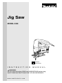
Jig Saw
MODEL 4324
DOUBLE
INSULATION
I N S T R U C T I O N
M A N U A L
WARNING:
For your personal safety, READ and UNDERSTAND before using.
SAVE THESE INSTRUCTIONS FOR FUTURE REFERENCE.
w w w. m a k i t a t o o l s. c o m
SPECIFICATIONS
Model
4324
Length of stroke
Max. cutting capacities
18 mm (11/16”)
Wood
65 mm (2-9/16”)
Mild steel
6 mm (1/4”)
Strokes per minute
500 - 3,100/min
Overall length
207 mm (8-1/8”)
Net weight
1.9 kg (4.2 lbs)
• Manufacturer reserves the right to change specifications without notice.
• Specifications may differ from country to country.
GENERAL SAFETY RULES
USA002-2
(For All Tools)
WARNING:
Read and understand all instructions. Failure to follow all
instructions listed below, may result in electric shock, fire and/or
serious personal injury.
SAVE THESE INSTRUCTIONS
Work Area
Electrical Safety
1. Keep your work area clean and well lit.
Cluttered benches and dark areas invite accidents.
4. Double insulated tools are equipped with
a polarized plug (one blade is wider than
the other.) This plug will fit in a polarized
outlet only one way. If the plug does not fit
fully in the outlet, reverse the plug. If it
still does not fit, contact a qualified electrician to install a polarized outlet. Do not
change the plug in any way. Double insula-
2. Do not operate power tools in explosive
atmospheres, such as in the presence of
flammable liquids, gases, or dust. Power
tools create sparks which may ignite the dust
or fumes.
3. Keep bystanders, children, and visitors
away while operating a power tool. Distractions can cause you to lose control.
2
tion
eliminates the need for the three wire
grounded power cord and grounded power
supply system.
5. Avoid body contact with grounded surfaces such as pipes, radiators, ranges and
refrigerators. There is an increased risk of
electric shock if your body is grounded.
6. Do not expose power tools to rain or wet
conditions. Water entering a power tool will
increase the risk of electric shock.
7. Do not abuse the cord. Never use the cord
to carry the tools or pull the plug from an
outlet. Keep cord away from heat, oil,
sharp edges or moving parts. Replace
damaged cords immediately. Damaged
cords increase the risk of electric shock.
8. When operating a power tool outside, use
an outdoor extension cord marked “W-A”
or “W”. These cords are rated for outdoor
use and reduce the risk of electric shock.
Personal Safety
9. Stay alert, watch what you are doing and
use common sense when operating a
power tool. Do not use tool while tired or
under the influence of drugs, alcohol, or
medication. A moment of inattention while
operating power tools may result in serious
personal injury.
10. Dress properly. Do not wear loose clothing or jewelry. Contain long hair. Keep
your hair, clothing, and gloves away from
moving parts. Loose clothes, jewelry, or long
hair can be caught in moving parts.
11. Avoid accidental starting. Be sure switch
is off before plugging in. Carrying tools with
your finger on the switch or plugging in tools
that have the switch on invites accidents.
12. Remove adjusting keys or wrenches
before turning the tool on. A wrench or a
key that is left attached to a rotating part of
the tool may result in personal injury.
13. Do not overreach. Keep proper footing
and balance at all times. Proper footing and
balance enables better control of the tool in
unexpected situations.
14. Use safety equipment. Always wear eye
protection. Dust mask, non-skid safety
shoes, hard hat, or hearing protection must
be used for appropriate conditions. Ordinary
eye or sun glasses are NOT eye protection.
Tool Use and Care
15. Use clamps or other practical way to
secure and support the workpiece to a
stable platform. Holding the work by hand or
against your body is unstable and may lead
to loss of control.
16. Do not force tool. Use the correct tool for
your application. The correct tool will do the
job better and safer at the rate for which it is
designed.
17. Do not use tool if switch does not turn it
on or off. Any tool that cannot be controlled
with the switch is dangerous and must be
repaired.
18. Disconnect the plug from the power
source before making any adjustments,
changing accessories, or storing the tool.
Such preventive safety measures reduce the
risk of starting the tool accidentally.
19. Store idle tools out of reach of children
and other untrained persons. Tools are
dangerous in the hands of untrained users.
20. Maintain tools with care. Keep cutting
tools sharp and clean. Properly maintained
tools with sharp cutting edges are less likely
to bind and are easier to control.
21. Check for misalignment or binding of
moving parts, breakage of parts, and any
other condition that may affect the tools
operation. If damaged, have the tool serviced before using. Many accidents are
caused by poorly maintained tools.
22. Use only accessories that are recommended by the manufacturer for your
model. Accessories that may be suitable for
one tool, may become hazardous when used
on another tool.
3
SERVICE
23. Tool service must be performed only by
qualified repair personnel. Service or maintenance performed by unqualified personnel
could result in a risk of injury.
24. When servicing a tool, use only identical
replacement parts. Follow instructions in
the Maintenance section of this manual.
Use of unauthorized parts or failure to follow
Maintenance instructions may create a risk of
electric shock or injury.
USE PROPER EXTENSION CORD: Make sure your extension cord is in good condition.
When using an extension cord, be sure to use one heavy enough to carry the current your
product will draw. An undersized cord will cause a drop in line voltage resulting in loss of
power and overheating. Table 1 shows the correct size to use depending on cord length and
nameplate ampere rating. If in doubt, use the next heavier gage. The smaller the gage number, the heavier the cord.
Table 1: Minimum gage for cord
Volts
120 V
Ampere Rating
More Than
Not More Than
0
6
10
12
6
10
12
16
25 ft.
Total length of cord in feet
50 ft.
100 ft.
150 ft.
AWG
18
18
16
14
16
16
16
12
16
14
14
12
14
12
Not Recommended
SPECIFIC SAFETY RULES
USB065-1
DO NOT let comfort or familiarity with product (gained from
repeated use) replace strict adherence to jig saw safety rules. If
you use this tool unsafely or incorrectly, you can suffer serious
personal injury.
1. Hold tool by insulated gripping surfaces
when performing an operation where the
cutting tools may contact hidden wiring or
its own cord. Contact with a “live” wire will
make exposed metal parts of the tool “live”
and shock the operator.
3. Avoid cutting nails. Inspect workpiece for
any nails and remove them before operation.
2. Always use safety glasses or goggles.
Ordinary eye or sun glasses are NOT
safety glasses.
6. Check for the proper clearance beyond
the workpiece before cutting so that the
blade will not strike the floor, workbench,
etc.
4. Do not cut hollow pipe.
5. Do not cut oversize workpiece.
7. Hold the tool firmly.
4
8. Make sure the blade is not contacting the
workpiece before the switch is turned on.
9. Keep hands away from moving parts.
10. Do not leave the tool running. Operate the
tool only when hand-held.
11. Always switch off and wait for the blade to
come to a complete stop before removing
the blade from the workpiece.
12. Do not touch the blade or the workpiece
immediately after operation; they may be
extremely hot and could burn your skin.
13. Some material contains chemicals which
may be toxic. Take caution to prevent
dust inhalation and skin contact. Follow
material supplier safety data.
SAVE THESE INSTRUCTIONS
WARNING:
MISUSE or failure to follow the safety rules stated in this
instruction manual may cause serious personal injury.
5
FUNCTIONAL
DESCRIPTION
•
002704
CAUTION:
Always be sure that the tool is switched off and
unplugged before adjusting or checking function on the
tool.
Selecting the cutting action
This tool can be operated with an orbital or a straight line (up
and down) cutting action. The orbital cutting action thrusts
the blade forward on the cutting stroke and greatly increases
cutting speed.
To change the cutting action, just turn the cutting action
changing lever to the desired cutting action position. Refer to
the table to select the appropriate cutting action.
1
1. Cutting action changing lever
Position
Cutting action
0
Straight line cutting action
I
Small orbit cutting action
II
Medium orbit cutting action
III
Large orbit cutting action
002707
Applications
For cutting mild steel, stainless steel and plastics.
For clean cuts in wood and plywood.
For cutting mild steel, aluminum and hard wood.
For cutting wood and plywood.
For fast cutting in aluminum and mild steel.
For fast cutting in wood and plywood.
Switch action
1
•
2
•
1. Lock button
2. Switch trigger
CAUTION:
Before plugging in the tool, always check to see that the
switch trigger actuates properly and returns to the “OFF”
position when released.
Switch can be locked in “ON” position for ease of
operator comfort during extended use. Apply caution
when locking tool in “ON” position and maintain firm
grasp on tool.
To start the tool, simply pull the switch trigger. Release the
switch trigger to stop.
For continuous operation, pull the switch trigger and then
push in the lock button.
To stop the tool from the locked position, pull the switch trigger fully, then release it.
6
002710
1
1. Speed adjusting dial
Speed adjusting dial
The tool speed can be infinitely adjusted between 500 and
3,100 strokes per minute by turning the adjusting dial. Higher
speed is obtained when the dial is turned in the direction of
number 6; lower speed is obtained when it is turned in the
direction of number 1.
Refer to the table to select the proper speed for the workpiece to be cut. However, the appropriate speed may differ
with the type or thickness of the workpiece. In general, higher
speeds will allow you to cut workpieces faster but the service
life of the blade will be reduced.
Workpiece to be cut
Wood
Mild steel
Stainless steel
Aluminum
Plastics
Number on adjusting dial
5-6
3-6
3-4
3-6
1-4
CAUTION:
• If the tool is operated continuously at low speeds for a
long time, the motor will get overloaded and heated up.
•
ASSEMBLY
•
The speed adjusting dial can be turned only as far as 6
and back to 1. Do not force it past 6 or 1, or the speed
adjusting function may no longer work.
CAUTION:
Always be sure that the tool is switched off and
unplugged before carrying out any work on the tool.
Installing or removing saw blade
•
CAUTION:
Always clean out all chips or foreign matter adhering to
the blade and/or blade holder. Failure to do so may
cause insufficient tightening of the blade, resulting in a
serious personal injury.
•
Do not touch the blade or the workpiece immediately
after operation; they may be extremely hot and could
burn your skin.
•
Always secure the blade firmly. Insufficient tightening of
the blade may cause blade breakage or serious personal
injury.
7
1
002715
To install the blade, loosen the bolt counterclockwise on the
blade holder with the hex wrench.
002716
With the blade teeth facing forward, insert the blade into the
blade holder as far as it will go. Make sure that the back edge
of the blade fits into the roller. Then tighten the bolt clockwise
to secure the blade.
3
2
1. Blade holder
2. Hex wrench
3. Bolt
1
2
To remove the blade, follow the installation procedure in
reverse.
3
NOTE:
1. Bolt
2. Roller
3. Blade
•
002727
1
2
1. Hook
2. Hex wrench
8
Occasionally lubricate the roller.
Hex wrench storage
When not in use, store the hex wrench as shown in the figure
to keep it from being lost.
Dust cover
002730
•
1
CAUTION:
Always wear safety goggles even when operating the
tool with the dust cover lowered.
Lower the dust cover to prevent chips from flying. However,
when making bevel cuts, raise it all the way.
1. Dust cover
002732
Anti-splintering device (optional accessory)
For splinter-free cuts, the anti-splintering device can be used.
To install the anti-splintering device, move the base all the
way forward and insert it between the two protrusions of the
base.
1
NOTE:
2
•
1. Anti-splintering device
2. Protrusions
OPERATION
CAUTION:
• Always hold the base flush with the workpiece. Failure to
do so may cause blade breakage, resulting in a serious
injury.
•
002743
1
The anti-splintering device cannot be used when making
bevel cuts.
Advance the tool very slowly when cutting curves or
scrolling. Forcing the tool may cause a slanted cutting
surface and blade breakage.
Turn the tool on without the blade making any contact and
wait until the blade attains full speed. Then rest the base flat
on the workpiece and gently move the tool forward along the
previously marked cutting line.
2
1. Cutting line
2. Base
9
002749
Bevel cutting
•
•
CAUTION:
Always be sure that the tool is switched off and
unplugged before tilting the base.
Raise the dust cover all the way before making bevel
cuts.
With the base tilted, you can make bevel cuts at any angle
between 0° and 45° (left or right).
002748
1
Loosen the bolt on the back of the base with the hex wrench.
Move the base so that the bolt is positioned in the center of
the cross-shaped slot in the base.
2
3
1. Hex wrench
2. Bolt
3. Base
002750
Tilt the base until the desired bevel angle is obtained. The
edge of the motor housing indicates the bevel angle by graduations. Then tighten the bolt to secure the base.
002757
Front flush cuts
1 2
1. Graduation
2. Edge
Loosen the bolt on the back of the base with the hex wrench
and slide the base all the way back. Then tighten the bolt to
secure the base.
10
Cutouts
Cutouts can be made with either of two methods A or B.
002762
A) Boring a starting hole
For internal cutouts without a lead-in cut from an edge,
pre-drill a starting hole 12 mm (1/2”) or more in diameter.
Insert the blade into this hole to start your cut.
1
1. Starting hole
002761
B) Plunge cutting
You need not bore a starting hole or make a lead-in cut if
you carefully do as follows.
(1) Tilt the tool up on the front edge of the base with the
blade point positioned just above the workpiece surface.
(2) Apply pressure to the tool so that the front edge of
the base will not move when you switch on the tool
and gently lower the back end of the tool slowly.
(3) As the blade pierces the workpiece, slowly lower the
base of the tool down onto the workpiece surface.
(4) Complete the cut in the normal manner.
002768
Finishing edges
To trim edges or make dimensional adjustments, run the
blade lightly along the cut edges.
Metal cutting
Always use a suitable coolant (cutting oil) when cutting
metal. Failure to do so will cause significant blade wear. The
underside of the workpiece can be greased instead of using
a coolant.
11
002772
Dust extraction
Clean cutting operations can be performed by connecting
this tool to a Makita vacuum cleaner. Insert the hose of the
vacuum cleaner into the hole at the rear of the tool. Lower
the dust cover before operation.
1
NOTE:
2
•
1. Dust cover
2. Hose
Dust extraction cannot be performed when making bevel
cuts.
Rip fence (optional accessory)
•
002775
CAUTION:
Always be sure that the tool is switched off and
unplugged before installing or removing accessories.
1. Straight cuts
When repeatedly cutting widths of 160 mm (6 - 9/32”) or
less, use of the rip fence will assure fast, clean, straight
cuts.
1
1. Rip fence (Guide rule)
002776
1
4
2
3
1.
2.
3.
4.
Hex wrench
Bolt
Rip fence (Guide rule)
Guide facing
12
To install, insert the rip fence into the rectangular hole on
the side of the base with the fence guide facing down.
Slide the rip fence to the desired cutting width position,
then tighten the bolt to secure it.
002777
1
2
3
1.
2.
3.
4.
4
Threaded knob
Guide facing
Rip fence (Guide rule)
Pin
2. Circular cuts
When cutting circles or arcs of 170 mm (6 - 11/16”) or
less in radius, install the rip fence as follows.
Insert the rip fence into the rectangular hole on the side
of the base with the fence guide facing up. Insert the circular guide pin through either of the two holes on the
fence guide. Screw the threaded knob onto the pin to
secure the pin.
Now slide the rip fence to the desired cutting radius, and
tighten the bolt to secure it in place. Then move the base
all the way forward.
002778
1
1. Rip fence (Guide rule)
MAINTENANCE
•
CAUTION:
Always be sure that the tool is switched off and
unplugged before attempting to perform inspection or
maintenance.
To maintain product SAFETY and RELIABILITY, repairs, carbon brush inspection and replacement, any other maintenance or adjustment should be performed by Makita
Authorized or Factory Service Centers, always using Makita
replacement parts.
13
ACCESSORIES
•
CAUTION:
These accessories or attachments are recommended for
use with your Makita tool specified in this manual. The
use of any other accessories or attachments might
present a risk of injury to persons. Only use accessory
or attachment for its stated purpose.
If you need any assistance for more details regarding these
accessories, ask your local Makita service center.
14
•
Jig saw blades
•
Hex wrench 3
•
Rip fence (guide rule) set
•
Anti-splintering device
•
Hose (For vacuum cleaner)
Memo
15
Memo
16
Cut
First-Class
Postage
Required
Post Office will
not deliver
without proper
postage.
Makita U.S.A., Inc.
14930 Northam Street
La Mirada, CA 90638-5753
Fold
17
MAIL THIS PORTION
Your answers to the following questions are appreciated.
1. This product was purchased from:
3. How did you learn about this product:
Other (
Magazine
Radio
Hardware/Lumber Store
From Dealer
Exhibition
Tool Distributor
Newspaper
From Friend
Industrial Supply
Store Display
Previous Usage
Construction Supply
Catalog
Other (
Home Center
)
2. Use of the product is intended for:
)
4. Most favored points are:
Construction Trade
Design
Repair Service
Industrial Maintenance
Features
Durability
Home Maintenance
Size
Power
Hobby
Price
Other (
Other (
)
)
Makita Brand
5. Any comments:
Paste
MODEL NO.
DAY
YEAR
SERIAL NO.
SEX
STATUS
INTL.
LAST NAME / COMPANY NAME
Married Single
M
F
STREET ADRESS
Paste
MONTH
Paste
Paste
Paste
Paste
DATE PURCHASED
Under 19
AREA
CODE
PHONE
20-29
30-39
Paste
AGE:
ZIP CODE
40-49
50-60
Over 60
Paste
Paste
STATE
Paste
CITY
Paste
Paste
BE SURE TO COMPLETE THE CUSTOMER’S PORTION OF THIS FORM AND RETAIN FOR YOUR RECORDS.
Please return this portion by facsimile or mail.
18
Facsimile No: (714) 522-8133
Paste
Paste
Paste
Paste
Paste
Paste
Paste
Paste
FACTORY SERVICE CENTERS
1-800-4-MAKITA
RETAIN THIS PORTION FOR YOUR RECORDS
ARIZONA
3707 E. Broadway Rd., Ste. 6
Phoenix, AZ 85040
(602) 437-2850
FLORIDA
750 East Sample Road
Pompano Beach, FL 33064
(954) 781-6333
MISSOURI
9876 Watson Road
St. Louis, MO 63126-2221
(314) 909-9889
PENNSYLVANIA
1704 Babcock Blvd.
Pittsburgh, PA 15209
(412) 822-7370
CALIFORNIA
41850 Christy St.
Fremont, CA 94538-5107
(510) 657-9881
GEORGIA
4680 River Green Parkway NW
Duluth, GA 30096
(770) 476-8911
NEBRASKA
4129 S. 84th St.
Omaha, NE 68127
(402) 597-2925
PUERTO RICO
200 Guayama St.
Hato Rey, PR 00917
(787) 250-8776
ILLINOIS
1450 Feehanville Dr.
Mt. Prospect, IL 60056-6011
(847) 297-3100
NEVADA
3375 S. Decatur Blvd.
Suites. 22 - 24
Las Vegas, NV 89102
(702) 368-4277
TENNESSEE
1120 Elm Hill P.
Suile 170 Nashville, TN 372
(615) 248-3321
14930 Northam St.
La Mirada, CA 90638-5753
(714) 522-8088
1970 Fulton Avenue
Sacramento, CA 95825
(916) 482-5197
7674 Clairemont Mesa Blvd.
San Diego, CA 92111
(858) 278-4471
16735 Saticoy St., Ste. 105
Van Nuys, CA 91406
(818) 782-2440
COLORADO
11839 E. 51st Ave.
Denver, CO 80239-2709
(303) 371-2850
MARYLAND
7397 Washington Boulevard,
Suite 104 Elkridge, MD 21075
(410) 796-4401
MASSACHUSETTS
232 Providence Hwy.
Westwood, MA 02090
(781) 461-9754
MINNESOTA
6427 Penn Ave. South
Richfield, MN 55423
(612) 869-5199
NEW JERSEY
251 Herrod Blvd.
Dayton, NJ 08810-1539
(609) 655-1212
NEW YORK
4917 Genessee Street
Cheektowaga, NY 14225
(716) 685-9503
OREGON
828 19th Avenue, N.W.
Portland, OR 97209
(503) 222-1823
TEXAS
12801 Stemmons Fwy Ste. 809
Farmers Branch, TX 75234
(972) 243-1150
12701 Directors Dr.
Stafford, TX 77477-3701
(281) 565-8665
3453 IH-35 North, Ste. 101
San Antonio, TX 78219
(210) 228-0676
WISCONSIN
Lincoln Plaza Shopping Ctr.
2245 S. 108th St. West Allis, WI
53227
(414) 541-4776
CUSTOMER’S RECORD
When you need service: Send
complete tool (prepaid) to one
of the Makita Factory Service
Centers listed, or to an Authorized
Makita Service Center. Be sure
to attach a letter to the outside of
the carton detailing the problem
with your tool.
Date Purchased
Dealer’s Name & Address
Model No.
Serial No.
19
WARNING
Some dust created by power sanding, sawing, grinding, drilling, and other
construction activities contains chemicals known to the State of California
to cause cancer, birth defects or other reproductive harm. Some examples
of these chemicals are:
• lead from lead-based paints,
• crystalline silica from bricks and cement and other masonry products, and
• arsenic and chromium from chemically-treated lumber.
Your risk from these exposures varies, depending on how often you do this
type of work. To reduce your exposure to these chemicals: work in a well
ventilated area, and work with approved safety equipment, such as those
dust masks that are specially designed to filter out microscopic particles.
MAKITA LIMITED ONE YEAR WARRANTY
Warranty Policy
Every Makita tool is thoroughly inspected and tested before leaving the factory. It is warranted to be free of
defects from workmanship and materials for the period of ONE YEAR from the date of original purchase.
Should any trouble develop during this one year period, return the COMPLETE tool, freight prepaid, to one of
Makita’s Factory or Authorized Service Centers. If inspection shows the trouble is caused by defective
workmanship or material, Makita will repair (or at our option, replace) without charge.
This Warranty does not apply where:
• repairs have been made or attempted by others:
• repairs are required because of normal wear and tear:
• the tool has been abused, misused or improperly maintained:
• alterations have been made to the tool.
IN NO EVENT SHALL MAKITA BE LIABLE FOR ANY INDIRECT, INCIDENTAL OR CONSEQUENTIAL
DAMAGES FROM THE SALE OR USE OF THE PRODUCT. THIS DISCLAIMER APPLIES BOTH DURING
AND AFTER THE TERM OF THIS WARRANTY.
MAKITA DISCLAIMS LIABILITY FOR ANY IMPLIED WARRANTIES, INCLUDING IMPLIED WARRANTIES OF
“MERCHANTABILITY” AND “FITNESS FOR A SPECIFIC PURPOSE,” AFTER THE ONE YEAR TERM OF THIS
WARRANTY.
This Warranty gives you specific legal rights, and you may also have other rights which vary from state to state.
Some states do not allow the exclusion or limitation of incidental or consequential damages, so the above
limitation or exclusion may not apply to you. Some states do not allow limitation on how long an implied
warranty lasts, so the above limitation may not apply to you.
Makita Corporation
Anjo, Aichi, Japan
Made in China
Huangpu Jiang Road, Kunshan Economic & Technical Development Zone, Jiangsu P.R. China
884205-945