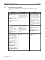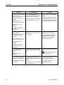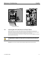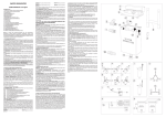
1
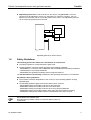
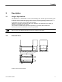
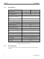
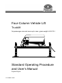
Four-Column Vehicle Lift Trucklift for passenger cars and vans up to max. gross weight of 8 t/10 t Standard Operating Procedure and User’s Manual Englisch/English D1 3602BA1-GB03 Trucklift EDITION Version 3 of the 22.10.1997 dated D1 3602BA1-GB03 Software Version from 4.3 © MAHA GMBH & CO. KG. All rights reserved. Any reproductions of this document, partial or complete, are only allowed with prior consent of MAHA GmbH & Co. KG. All rights reserved in cases of patent granting or registration of design. The contents of this version have been checked with great care. However, errors cannot be fully excluded. Please contact MAHA should you find errors of any kind. Subject to technical change without notice. These instructions are intended for users with previous technical knowledge in the field of vehicle testing technology as well as basic computer knowledge and MS-Windows operating system application. Windows and Windows for Workgroups is a registered trademark of the Microsoft-Corporation. MANUFACTURER MAHA Maschinenbau Haldenwang GmbH & Co. KG. Hoyen 20 D-87490 Haldenwang/Allgäu Telephone: 08374 / 585-0 Telefax: 08374/ 585-499 Internet: e-mail: http://www.maha.de [email protected] SERVICE MAHA Maschinenbau Haldenwang GmbH & Co. KG. - Service dept. Hoyen 20 D-87490 Haldenwang/Allgäu II Hotline: 08374 / 585 + extension 260 for brake testers, test lanes 280 for lifting technology 290 for performance testers, exhaust and air condidioning service equipment Service: Telefax: 08374 / 585-110 bis - 113, - 115 08374 / 585-491 Trucklift TABLE OF CONTENTS 1 Safety Instructions .................................................................................................... 1 1.1 1.2 1.3 1.4 2 Description ................................................................................................................ 5 2.1 2.2 2.3 2.4 3 Controls.......................................................................................................................................... 9 Vehicle Tracks ............................................................................................................................. 10 Driving onto the Lift ...................................................................................................................... 11 Lifting............................................................................................................................................ 12 Working on Raised Vehicles........................................................................................................ 12 Lowering ...................................................................................................................................... 13 Locking the Lift to Prevent Unauthorised Operation.................................................................... 13 Maintenance, Troubleshooting .............................................................................. 15 5.1 5.2 5.3 5.4 6 General Information ....................................................................................................................... 7 Installation Location ....................................................................................................................... 7 Foundations ................................................................................................................................... 8 Operation ................................................................................................................... 9 4.1 4.2 4.3 4.4 4.5 4.6 4.7 5 Usage, Applications ....................................................................................................................... 5 General View ................................................................................................................................. 5 Specifications................................................................................................................................. 6 Noise Emissions ............................................................................................................................ 6 Installation ................................................................................................................. 7 3.1 3.2 3.3 4 Safety Information.......................................................................................................................... 1 Further Information ........................................................................................................................ 2 Safety Features.............................................................................................................................. 2 Safety Guidelines........................................................................................................................... 3 Maintenance ................................................................................................................................ 15 Repair Notes ................................................................................................................................ 16 Troubleshooting Checklist ........................................................................................................... 17 Lowering the Lift in the Event of a Power Failure ........................................................................ 19 Warranty, Service .................................................................................................... 21 6.1 6.2 6.3 Warranty ...................................................................................................................................... 21 Warranty Exclusion Clause.......................................................................................................... 21 Service ......................................................................................................................................... 22 III Trucklift IV Trucklift 1 Safety Instructions 1.1 Safety Information Safety Instructions are provided to warn about dangerous situations and to help avoid injury to people. The truck lift is only to be used for its intended purpose as described in the operating instructions! Only trained authorized personnel may operate the truck lift. Explosion protection! The truck lift is not to be used in rooms liable to contain explosive mixtures! Standard lifts have no EX-protection! The main power switch serves as Emergency-Off switch! In case of emergency, turn switch to 0-position. Persons are not permitted in the danger zone during lifting and lowering cycles. Unauthorized persons may not in any way be positioned underneath the lifted vehicle! The net load capacity stated on the identification plate of the lift may not be exceeded! Persons may not climb on or be transported on the lift. Before repair-/maintenance-/set up work turn off main switch and secure against tampering. Secure the lift from unauthorized usage by locking the main switch. All work done on electrical parts of the equipment is to be carried out by trained, qualified electricians or service technicians only. Protect all parts of the machinery from humidity and moisture. D1 3602BA1-GB03 1 Trucklift 1.2 Safety Instructions Further Information At installation pay attention to the following: Standard lifting platforms may not be operated in washing halls, rooms with high humidity or outdoors! The lifting platform must be protected from any form of water splashing! Never clean the lifting platform with high pressure cleaners or steam cleaners! In rooms with very low ceilings it is recommended to install a ceiling light barrier. This can be ordered from the manufacturer. For safe operation pay attention to the following: Read the standard operating procedures and user`s manual thoroughly! MAHA will not accept and is not liable for any claims for damage or service costs incurred due to noncompliance with these operating instructions. All official Accident Prevention Regulations must be thoroughly complied with! Damages to low-lying vehicle parts are not covered by the warranty. Keep the lifting platform and the surrounding work area clean. Do not deposit any parts on the support arms or on the driving platform. The vehicle should be driven slowly onto the lifting platform to avoid putting any unnecessary strain on vehicle and lifting platform. On lifting platforms equipped with an axle jack pay close attention that no objects are below the axle jack. Balancing work on the lift while the platform is being loaded is forbidden. The vehicle may roll off the driving platform. Pull the parking brake of the vehicle after entering the lifting platform. All work done on impulse sensors and proximity switches should be carried out by trained electricians. 1.3 Safety Features The TRUCKLIFT is equipped with the following safety features: Electronic lift synchronisation monitoring. This system monitors all the lifting carriages and ensures that they are synchronised during lifting and lowering. If one carriage blocks all the drive motors are switched off automatically. Electronic bearing nut monitoring system on all four columns. If a bearing nut breaks the system only permits the unit to be moved to its lower starting position. Bearing nut wear indicator, lets you know in good time when the bearing nuts need to be replaced. Drive belt breakage safety system on all four columns. All motors are switched off automatically if a drive belt is defective. Motor overload protection system on all four columns. Catch nuts, which support the load on the lift in the event of failure of the bearing nuts. The main switch doubles as an emergency off switch. In an emergency, the unit can be switched off by turning the switch to position 0. 2 D1 3602BA1-GB03 Fehler! Verweisquelle konnte nicht gefunden werden. Trucklift Adjustable guard rails around the lift and on the ramps. The guard rails on the four columns must be adjusted in such a way, that there is a clearance of approx. 150 mm between the extension and the connection plates of the column. The adjustable guard rail can be locked by tightening the M 8 screw. 150 Adjustable guard rails on all four columns 1.4 Safety Guidelines The following points were taken into consideration at construction: The safety regulations correspond with the prEN 1493. The lifting platform meets the safety demands of the following guidelines: - 89/392/EWG in connection with 91/368/EWG and 93/44/EWG EG-Maschinery Guidelines. - 73/23/EWG EG-Low Voltage Guidelines - 89/336/EWG EG-guidelines regarding electro-magnetic tolerance. The CE-Declaration of Conformity is attached to the Operating Instructions or Test Booklet. Pay attention during operation: The Accident Prevention Regulations of the country in which the lifting platform is being operated apply. The following guidelines apply within the European Union countries: - 89/391/EWG Safety and Health Protection for the Employee. - 89/654/EWG Safety and Health Protection in the Work Area. - 89/655/EWG Safety and Health Protection when using Working Materials. - 89/656/EWG Safety and Health Protetion when using personal Protective Clothing. - 92/58/EWG Safety and/or Health Protection Identification at the Place of Work. EU-Guidelines are available from DITR German Information Center for Technical Rules in DIN e.V. 10772 Berlin D1 3602BA1-GB03 3 Trucklift 4 Safety Instructions D1 3602BA1-GB03 Trucklift 2 Description 2.1 Usage, Applications The TRUCKLIFT 8 / TRUCKLIFT 10 is a device for lifting motor vehicles up to a maximum gross weight of 8,000 kg / 10000 kg, with a maximum load of 6000 kg / 6600 kg permitted on any pair of columns. The maximum lifting height of the unit is 2,1 m, making it easy to work on the underside of the vehicle, even for taller staff members. TRUCKLIFT is designed primarily for lifting vans. However, the vehicle tracks can easily be adjusted for lifting normal cars as well. The lift must be installed and prepared for operation by a properly trained technician. Structural and technical alterations to the lift are prohibited. Always observe the detailed operating and service instructions provided. 2.2 General View Column 4 is the control column. D1 3602BA1-GB03 5 Trucklift 2.3 Descriptions Specifications Max. rated load in t Trucklift 8 Trucklift 10 8 10 Machine weight in kg 3500 Column height HS in mm 2650 Max. lifting height Ho in mm 1975 Height above ground surfaceFehler! Textmarke nicht definiert. Hu in mm Height to guard rail lower edge HB in mm 200 5810 Overall height HG in mm 5850 Inside column width BL in mm 3200 Max. horizontal clearance BM in mm 2980 Overall width BG in mm 3800 Inside track width BE in mm 1100 - 1640 Vehicle track width BB in mm 617 Column spacing LS in mm 6200 Overall baseplate length LG in mm 6510 Effective vehicle track length LF in mm 5940 Overall length L in mm 7800 Lifting period in s 54 Lifting travel in mm 1775 Lifting speed in mm/s ca. 35 Anchoring dowels 20 x UPAT composite dowels UKA 3 M 16 Concrete grade min. BN 25 Motor output 4 x 2,2 kW Voltage supply 3 x 400 V + N + PE; 50 Hz Specifications subject to change without notice! 2.4 Noise Emissions The noise emissions of the lift in the area occupied by the operating personnel are lower than 70 dB (A) 6 D1 3602BA1-GB03 Trucklift 3 Installation 3.1 General Information TRUCKLIFT is normally installed by the manufacturer's own trained technicians. However, the lift can also be installed by the operator's own technical staff, provided that they are properly trained, with the necessary skills. It is important that they should have experience in the proper use of composite dowels and the proper installation of the electrical connections in accordance with the VDE regulations. 3.2 Installation Location The lift can be installed in any suitable location. The only restriction is that the standard version of the lift is not rated for use in rooms with explosive atmospheres The installation location must be provided with the necessary power supply by the operator: 3~/N + PE 400/230 V, 50 Hz. The operator must also see to it that the power supply is protected with a T35A circuit breaker in accordance with the VDE 0100 regulation. The standard point for the power supply cable inlet to the lift is at the top in the control column. However, the power supply cable can also be routed in through the hole provided in the baseplate. In both variants, the cable must be protected with a suitable cable support sleeve. The power supply cable must be connected to the terminals of the main switch in the control console on the control column. Before installation, suitable foundations conforming to the specifications of the manufacturer MAHA must be provided. They must either be built specifically for installation of the unit, or the operator must provide evidence that they conform to the specifications. The installation location must be perfectly flat and level. If the foundations are installed in the open or in rooms where winter weather conditions or frost can be expected, the foundations must be sunk down to frost depth. D1 3602BA1-GB03 7 Trucklift 3.3 Installation Foundations The concrete used for the foundations must be at least grade B25 and reinforced. Because of the anchoring dowels used, the concrete base slab must also have a minimum thickness of 200 mm. The operator must provide evidence of the base slab load bearing capacity. The foundations plan is also available from MAHA. 8 D1 3602BA1-GB03 Trucklift 4 Operation 4.1 Controls The TRUCKLIFT unit has four controls. The main switch is used to turn the entire system on and off, and also doubles as an emergency off switch. Vor Öffnen des Gerätes Haupschalter ausschalten! Sicherheitsbestimmungen 1 The main switch must always be easily accessible. Bedienung: 0 Its position should never be changed. The light switch is identified by a light symbol. Turn this switch to the right to switch the light on. The raise button is identified by an arrow pointing up. The lift stops moving immediately as soon as you release the button. The lift also stops automatically when it reaches its upper travel limit. The lower button is identified by an arrow pointing down. The lift stops moving immediately as soon as you release the button. The lift also stops automatically when it reaches its lower travel limit. D1 3602BA1-GB03 9 Trucklift 4.2 Ôperation Vehicle Tracks The vehicle tracks can be moved laterally on the crossbars to adjust the width to match the track width of the vehicle to be lifted. Normally, you will only need to adjust the left track. Track to be adjusted To adjust the track width, first remove the retaining pins at the front and rear. Then move the track in the desired direction by inserting a lever in the retaining lug and levering against one of the holes in the perforated section below. This must be done both at the front and the rear, otherwise the track will not be straight. Adjusting the track Front retaining pin After adjusting the track position you must secure it again with the retaining pins! You do not have to adjust the other track, but you can if you wish, for example in order to centre a vehicle over a working pit. To do this, you must first unscrew the retaining disks on the two retaining pins, and then unscrew and remove the pins themselves. You can then adjust the position of the track. Since this only needs to be done once, no leverage aids are provided. Fixed track" After you have adjusted the track position you must replace the retaining pins. Retaining pin 10 D1 3602BA1-GB03 Operation 4.3 Trucklift Driving onto the Lift The control console is mounted on lifting column 1. The main switch is on the side of the console. Turn this switch to position 1 to turn on the power. The lift is then ready for operation. 1 0 The main switch doubles as the emergency off switch. In emergencies, simply turn the switch to the 0 position to switch off the lift! Remove all tools, chocks, stands etc. from the working area of the lift. 1. 2. Always make sure that the working area is kept free of excessive dirt! Lower the lift (see Lowering) until it stops automatically in its starting position. Drive the vehicle onto the lift tracks and stop so that it is centred between the end columns. = = The vehicle tracks of the lift must be adjusted to match the track width of the vehicle. The actual gross weight of the vehicle should never exceed the maximum rated load of 8 t. Secure the vehicle so that it can't roll away (motor off, hand brake on, gear engaged, chocks under the wheels). D1 3602BA1-GB03 11 Trucklift 4.4 Ôperation Lifting You can lift the vehicle once it is properly positioned on the lift and secured against rolling away. To start the lift, press the '###' button. The lift stops as soon as you release the button. Nobody should ever be in the working area of the lift while a vehicle is being lifted! Sicherheitsbestimmungen Bedienung: Vor Öffnen des Gerätes Haupschalter ausschalten! Whenever the lift is moved you should always keep an eye on the load and everything used to keep the load in place! Lifting people and climbing on the lift or on the vehicle when the lift is raised are all strictly prohibited! You can now lift the vehicle to the desired height. 4.5 Working on Raised Vehicles Never place any items on the lift or the vehicle tracks! Lifting people and climbing on the lift or on the vehicle when the lift is raised are all strictly prohibited! Secure the vehicle so that it can't roll away (motor off, hand brake on, gear engaged, chocks under the wheels). You can turn on the light by turning the light switch to the right. 12 D1 3602BA1-GB03 Operation 4.6 Trucklift Lowering Sicherheitsbestimmungen Before lowering, always make absolutely sure that nobody is in the working area of the lift! Bedienung: Remove all tools, chocks, stands etc. from the working area of the lift. Vor Öffnen des Gerätes Haupschalter ausschalten! Press the 'Ä' key until the platform is in its lowest position. The lift stops automatically in its starting position. 4.7 Locking the Lift to Prevent Unauthorised Operation When the lift is not being used you should always lock it to prevent unauthorised operation! 1 0 To lock the main switch, first turn it to the 0 position. Then press in the protruding pin and lock the switch in this position with a padlock. This prevents unauthorised operation of the lift. D1 3602BA1-GB03 13 Trucklift 14 Ôperation D1 3602BA1-GB03 Trucklift 5 Maintenance, Troubleshooting 5.1 Maintenance Regular maintenance is necessary to ensure reliable operation of the lift and a long service life. a) The support arm extension and the support disc threading should be well greased. It is recommended to use lithium soap grease. The oil level of the oil pan should be checked quarterly. It is located on the carriage slides behind the spindle cover sheet. (see the upper part of the diagram to the right) The pan should have at least 5 mm of oil in it. If the oil is not up to this level refill it. The neck of the oil can be directly applied through the brush cover of the column. 0-2mm b) Use only SAE 140 gear or the special oil available from the manufacturer, order no. 360004. D1 3602BA1-GB03 15 Trucklift Maintenance, Troubleshooting c) Wear and tear on the support nut must be checked annually. Remove the plastic cap from the spindle cover sheet and move the carriage slides so that the control drill holes lines up with the window. If there is no visible gap this is an indicatioin that the support nut is worn down beyond the permissable limit. The support nut must be replaced. The gap is approximately 2 mm. ex factory. When the wear limit is reached the lift must be shut down until the bearing nuts have been replaced. Lock the main switch to ensure that nobody can use the machine. 5.2 Repair Notes Only trained, skilled electricians are allowed to check impulse sensor and proximity switches. Immediately contact your MAHA dealer or the MAHA service center when there are problems with impulse sensors or proximity switches. Unskilled work on electrical parts of the lifting platform can be life threatening. The main switch should be switched off and secured before any repair work or malfunction troubleshooting is done on the lift! Malfunctions due to unskilled repair or adjustment work are not covered by the warranty. 16 D1 3602BA1-GB03 Maintenance, Troubleshooting 5.3 Trucklift Troubleshooting Checklist The following checklist will help your service technicians to locate faults in the event of problems. Problem When lifting, lift stops of its own accord at an arbitrary height. The LED on the circuit board lights up (see ill. on next page). Possible cause a) Excessive load on the lift. b) The distance between the pulse encoder and the drive pulley is too great. Remedy a) Check whether the load exceeds the rated maximum lifting capacity. Check the jackscrew lubrication and the tension of the toothed drive belt. b) Check impulse encoder distance (have it corrected, if necessary). Lowering from this position is possible. Lifting should then be possible again after lowering the lift by at least 2 cm. When lowering, the lift stops of its own accord at an arbitrary height. a) The lift has run into an obstacle, lifting out the jackscrew. The LED on the circuit board lights up (see ill. on next page). b) The distance between the pulse encoder and the drive pulley is too great. Lowering should then be possible again after raising the lift by at least 5 cm. No signals from the upper pulse encoders. Check the upper pulse encoders. Lifting from this position is possible. Lift stops in the upper position. After pressing the RESET button followed by the "Lower" button, all motors activate briefly and then stop.(see ill. on next page) a) Remove the obstacle. b) Check the upper pulse encoder. When the "Lift" button is pressed the motors activate again briefly and then stop. Pressing the buttons again produces no further reaction from the lift. The red LED on the circuit board lights up after about 5 seconds.(see ill. on next page) D1 3602BA1-GB03 17 Trucklift Maintenance, Troubleshooting Problem Possible cause Remedy The lift stops at a height of a) The distance between the a) Check the wear of the bearing approx. 260 mm catch nuts and the jackscrew nuts. (measured from the floor to bearing nuts is too small. b) Check the distance between the lower edge of the b) A proximity switch is defective the proximity switches and the carriage). switching cams on the frame or its setting is incorrect. The lift can only be and on the catch nuts .5 mm). lowered from this position. Further raising is not possible. The LED on the circuit board blinks.(see ill. on next page) The lift stops at a height of No signal pulse from the approx. 400 mm switching cam on the frame or (measured from the floor to the catch nut. the lower edge of the carriage). The lift can only be lowered from this position. Check the proximity switches. (Call MAHA-Service Dept.). Check the distance between the proximity switches and the switching cams on the frame and on the catch nuts. Further raising is not possible. The LED on the circuit board blinks.(see ill. on next page) The lift can only be moved to its lower starting position. A bearing nut is broken and the load is being borne by the catch nut. Lifting is no longer possible. At the beginning of lifting All motors are starting up the lift stops and the power simultaneously. This causes a supply circuit breaker trips. voltage peak that trips the circuit breaker Neither lifting nor lowering DIP switch 4 is set to "ON".(see are possible. ill. on next page) 18 Have the bearing nut repaired. Shut down the lift and lock the main switch! Change the setting of DIP switch 4 on the control PCB to "OFF".(see ill. on next page). This starts the motors in a staggered sequence. D1 3602BA1-GB03 Maintenance, Troubleshooting Trucklift DIP RESET LED 1234 470nJ o63 Reset ON DIP 470nJ o63 Ver. KEB 470nJ o63 Appl. K3 K4 K7 MK1 470nJ o63 470nJ o63 LED K8 MK1 470nJ o63 470nJ o63 470nJ o63 470nJ o63 K1 1 0 K5 K2 1 0 1 0 K6 MK1 1 0 S2.2 S3.2 Q1 PE 230V 50/60Hz 18V 0,25A 5.4 GERTH BV 4218-1 VDE 0551 T 60/E Control cabinet, opened ERO F1776-4223471 9220/ ERO F1776-4223471 9220/ Control PCB Lowering the Lift in the Event of a Power Failure Remove the motor cover hoods. Each spindle can be turned separately at the large drive pulleys with a ratchet (nut size 36) to lower the carriages. When doing this, two persons should lower the front column pair at the same time and then the back column pair. As soon as the power returns, synchronise the carriages again by pressing "###" and holding it down until all movement stops. The height difference between the lateral column pair should never be more than 20 mm. The height difference between the column pair in driving direction may not exceed 100 mm! Important: In the event of a power failure the lifting carriages should only be lowered! D1 3602BA1-GB03 19 Trucklift 20 Maintenance, Troubleshooting D1 3602BA1-GB03 Trucklift 6 Warranty, Service 6.1 Warranty Subject to the provisions of their General Terms and Conditions of Business, Maschinenbau Haldenwang (MAHA) undertakes to repair or replace any defective components free of charge during the warranty period if the product is sent to MAHA – either directly or through an authorised MAHA dealer – or if the product is repaired or installed by authorised personnel. This warranty is only provided for products installed by authorised personnel. Damage resulting from improper alterations or grossly negligent damage to the product is excluded from the warranty. No warranty coverage for MAHA products can be provided without a fully completed Warranty Registration Card and a Warranty Application, together with a completed and signed original sale receipt showing the date of purchase and the serial number of the product. Proper regular servicing is also a requirement for warranty coverage. 6.2 Warranty Exclusion Clause All warranty coverage is subject to the condition that our products must be used properly for their intended purpose, in accordance with the Installation and Maintenance Instructions and Operating Instructions, including any subsequent operating and service information provided. Normal functional wear and tear on vehicle components are excluded from the warranty. The warranty does also not cover any damage to vehicles and/or our equipment or other products caused by alterations to motor vehicles or other deviations of the motor vehicles from the series model specifications. D1 3602BA1-GB03 21 Trucklift 6.3 Warranty, Service Service MAHA has customer service offices in many countries all over the world. You can contact these offices at any time to obtain answers to any questions you may have regarding MAHA products. If your product needs repair you can always contact your dealer, or you can contact MAHA directly. A charge will be made for repairs after the end of the warranty period. You can reach our central customer service office at the address below: MAHA Maschinenbau Haldenwang GmbH & Co. KG. D-87490 Haldenwang/Allgäu Telephone : 08374 / 585-0 Telefax : 08374 / 585-491 Internet : http://www.maha.de E-Mail : [email protected] 22 D1 3602BA1-GB03