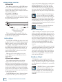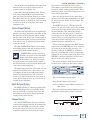
1
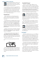
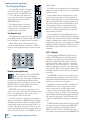
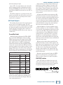
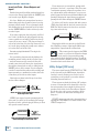
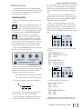
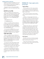
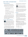
MIXER ANATOMY: CHAPTER 2
Inputs, Outputs, and Related Controls
the mixer. So, while there’s a wide adjustment range
for both mic and line inputs, the mic inputs have
higher gain.
Mackie E-Z Interfacing
Concerned about levels, balancing, impedance,
polarity, or other interface goblins? Don’t be. On
your Mackie mixer, you can connect almost anything
almost anywhere, with nary a care. Here’s why:
•
Every main input and output is balanced.
•
Every 1/4" input and output jack also accepts
unbalanced connections.
Don’t forget the Level-Setting Procedure at the beginning of this book. Mic
and line inputs are happiest when running at the optimum levels. That procedure will get
you there.
•
Every input is designed to accept virtually any
output impedance.
•
The main left and right mix outputs can deliver +28 dBu into a 600 ohm load (that’s hot!)
•
All the other outputs can deliver +22 dBu into
a 600 ohm load (that’s plenty).
•
Check the Tips section and Glossary for more information about terms we’ll be using here like operating
level, impedance, balanced, unbalanced, XLR, and
TRS. Also study the mixer block diagrams, as each
one is worth a thousand words or more.
Mic Inputs
Mackie mixers include phantom-powered, balanced XLR microphone inputs just like the big studio
mega-consoles, and for exactly the same reason:
A fully balanced circuit is excellent at rejecting
hum and noise, and phantom powering means that
condenser mics can be used without external power
supplies or batteries.
All the outputs are in phase with the inputs.
All Mackie mixers have both microphone and linelevel inputs. Some channels have both, some channels have only line-level inputs. Consult your mixer’s
quick start guide (or just look at the connector
panel) for the exact arrangement. Below is the rear
panel of the 1604-VLZ PRO.
You can plug in almost any kind of mic that has a
standard male XLR-type connector without fear of
overloading the preamp. Professional ribbon, dynamic, and condenser mics all sound great through
these inputs.
Mic? Line? – What’s The Difference?
Microphones produce a relatively low
voltage, generally in the range of 1 to 250
millivolts, depending on the sensitivity of
the mic, and how loud the sound is. Voltages in the
0.15 to 3 volt range are considered to be line-level.
These aren’t rules or standards, just ways of talking
about two widely different operating voltage ranges,
both of which are common in audio.
XLR Input Connectors – Mic wiring
Nearly all professional mics are designed to connect to a low impedance input, and employ balanced
wiring terminating in an XLR-style plug. You’ll find an
illustration and wiring diagram in the Tips section,
chapter 9. We use the wiring convention:
A microphone typically requires 20 to 60 dB of gain
in order to bring its signal up to the mixer’s operating level. A line-level signal requires little if any gain,
and may need to be brought down in level to match
120 VAC 50/60 Hz 20W
1A/250V SLO-BLO
POWER
ON
PHANTOM
ON
MAIN INSERT
(TIP SEND
RING RETURN)
MAIN OUT
BAL/UNBAL
L
TAPE
INPUT
R
MONO
INSERT
LINE
16
LINE
MIC 16
XD R
MIC PR
E
15
LINE
MIC 15
XD R
MIC PR
E
14
LINE
MIC 14
XD R
MIC PR
E
MIC 13
XD R
L
L
L
(MONO)
(MONO)
R
R
R
2
DIRECT OUT
BAL/UNBAL
5
3
1
7
5
3
1
6
4
2
8
6
4
2
13
LINE
MIC PR
E
12
LINE
MIC 12
XD R
MIC PR
E
11
LINE
MIC 11
XD R
MIC PR
E
10
LINE
MIC 10
XD R
MIC PR
E
9
LINE
MIC 9
XD R
MIC PR
E
8
LINE
MIC 8
XD R
MIC PR
E
7
LINE
MIC 7
XD R
MIC PR
E
6
LINE
5
LINE
4
LINE
INSERT
INSERT
INSERT
INSERT
3
LINE
2
BAL
UNBAL
BAL
UNBAL
BAL
UNBAL
BAL
UNBAL
BAL
UNBAL
BAL
UNBAL
BAL
UNBAL
BAL
UNBAL
BAL
UNBAL
BAL
UNBAL
INSERT
INSERT
INSERT
INSERT
INSERT
INSERT
INSERT
INSERT
BAL
UNBAL
BAL
UNBAL
BAL
UNBAL
BAL
UNBAL
BAL
UNBAL
4
1
2
+6
INSERT
INSERT
INSERT
R
3
(MONO)
R
R
OO
4
L
R
CAUTION:
TO REDUCE THE RISK OF
FIRE REPLACE WITH SAME
TYPE FUSE AND RATING
AUX SEND
BAL/UNBAL
AUX RETURN
BAL/UNBAL
1
3
L
L
UTILISE
UTILISE UN
UN FUSIBLE
FUSIBLE DE
DE RECHANGE
RECHANGE DE
DE MÊME
MÊMETYPE.
TYPE.DEBRANCHER
DEBRANCHERAVANT
AVANT DE
DE REMPLACER
REMPLACER LE
LE FUSIBLE
FUSIBLE
SUB OUT
BAL/UNBAL
C-R OUT
BAL/UNBAL
TAPE
OUTPUT
L
Pin 1 = shield
Pin 2 = positive (+ or hot)
Pin 3 = negative (- or cold)
LINE
MIC 6
MIC 5
MIC 4
MIC 3
MIC 2
MIC 1
XD R
XD R
XD R
XD R
XD R
XD R
MIC PR
E
MIC PR
E
MIC PR
E
MIC PR
E
1
BAL
UNBAL
MIC PR
E
MIC PR
E
XDRTM EXTENDED DYNAMIC RANGE MIC PREAMPLIFIERS ARE PROPRIETARY TO MACKIE DESIGNS, INC.
CONCEIVED, DESIGNED, AND MANUFACTURED BY MACKIE DESIGNS INC • WOODINVILLE • WA • USA • MADE IN USA • FABRIQUE AU USA • COPYRIGHT ©1998 • THE FOLLOWING ARE TRADEMARKS OR REGISTERED TRADEMARKS OF MACKIE DESIGN INC.: "MACKIE", "VLZ", "XDR", AND THE "RUNNING MAN" FIGURE • US PATENT NUMBER 29/049,129
Compact Mixer Reference Guide
17
MIXER ANATOMY: CHAPTER 2
Even though microphones produce alternating current (AC), they have a definite
polarity orientation. Be sure that you don’t
reverse the wires between pins 2 and 3.
Did you pick up a cool retro mic at a yard sale that
has a 1/4" phone plug instead of an XLR? Chances are
it’s a high impedance mic and it will require a matching transformer in order to sound its best with your
mixer. Plug-in transformers available from several
sources will not only match the impedance and signal
level, but will adapt the plug too.
Phantom Power
Most condenser mics require phantom power, a
system whereby the mixer supplies a DC voltage to
the mic’s electronics through the same wires that
carry audio.
The phantom power on all Mackie mixers (except
the Onyx series) is globally controlled by the PHANTOM switch on the rear panel (one switch for each
group of 8 mics on the 8-Bus). A PHAMTOM LED on
the front panel will remind you that phantom power
is turned on. The Onyx mixers have a 48V switch and
LED indicator on each channel for selective control of
phantom power.
“Phantom” owes its name to the ability to disappear
when it’s not needed, like when connecting dynamic
mics (Shure® SM57/SM58, for instance) that don’t
require external power.
The most common phantom power supply is 48
volts. All Mackie mixers have a 48 volt phantom
supply with the exception of the PPM series, which
provide 15 volts. Some microphones will operate just
fine on lower voltages while others require the full 48
volts. Check your mics’ specs.
Here’s what the phantom powering circuit looks
like:
2
1
0V
3
48 V 48 V
There’s 48 volts between pins 1 and 2 and between
pins 1 and 3. Since pins 2 and 3 are both at the same
DC potential, the voltage difference between them is
zero. That’s why an unpowered mic doesn’t “see” the
voltage.
18
Compact Mixer Reference Guide
Barenekked Preamps!
People have thought highly of Mackie mic preamps for a long time, so when it was time to put the
engineers to work on some new designs, they brought
us the Onyx series, which includes the 800R. This answers a popular customer request for a rack-mounted
unit with eight mic preamps, but no other mixer
features. The 800R has a few neat tricks up its sleeve
which we’ll discuss later, but we wanted to mention it
in this discussion about microphone preamps.
Dynamic and ribbon mics don’t like to
see DC voltage applied to their sensitive
insides. Normally it won’t be, but a shorted
or miswired mic cable can cause the full voltage to
appear across the sensitive microphone element. Be
sure that your cables are in good condition before applying phantom power.
Also, unless you know for certain that it is safe to
do so, never plug single-ended (unbalanced) microphones, instruments, or electronic devices into the
MIC input jacks if the phantom power is on.
Practice safe phantom powering! Plug in
your mics with phantom power switched
off! The XDR preamps used in many Mackie
mixers have extra protection against damage from
“hot plugging,” but your mics don’t. Get into the habit
of plugging mic cables in with the phantom power off,
then turning it on.
Line Inputs
Line inputs on Mackie mixers are on 1/4" TRS (tipring-sleeve - the parts of the mating plug) jacks. All
Mackie line inputs are balanced and present a moderately high impedance load, around 10 kΩ, depending on the model and the particular input. As we’ve
seen from our block diagram tour, LINE IN jacks on
channels with both line and mic inputs share circuitry
(but not phantom power) with the mic preamps.
You can use these inputs for virtually any line-level
signal. With proper adjustment of the TRIM control,
they’ll accept signals over a range of approximately
–45 to +16 dBu.
Some Mackie mixers are equipped with stereo line
inputs. These have two line-level input jacks which
share a common set of controls. To learn how signals
are routed from these inputs, consult the block diagram or quick start guide for your mixer, or check the
Controls section of this manual.
MIXER ANATOMY: CHAPTER 2
Always be sure to perform the Level-Setting Procedure when connecting to LINE inputs that have
TRIM controls, and check the level and adjust it
externally on the stereo inputs without TRIMs.
sound, but the guitar will lose punch and treble. The
proper way to connect an instrument pickup directly
to a Mackie mixer is to use a Direct Box (or DI =Direct Injection) between the guitar and a MIC input.
To connect balanced sources to the line-level
inputs, use a 1/4" tip-ring-sleeve (TRS) plug, the type
found on some stereo headphones:
Hi-Z Guitar Inputs
1
YX MIC PR
ON
E
RING SLEEVE
SLEEVE RING TIP
TIP
RING
HI-Z
1
TIP
MIC
HI-Z
SLEEVE
To connect unbalanced line-level sources, use
a cable with 1/4" mono (TS) plugs. In music store
lingo, that’s an “instrument cable” or “quarter inch
patch cord.” When a TS plug is inserted into a TRS
jack, the Ring (low signal) and Sleeve (ground) get
connected together.
See the Mixer Tips section for more information on
balanced and unbalanced connections.
The TRIM Control
The TRIM control adjusts the
input sensitivity of the MIC or LINE
IN jack, to match the input signal
to the operating range of the mixer.
0
60
+15dB -45dB
On all Mackie mixing consoles with
the exception of the PPM series,
the TRIM control is located at the top of the channel
strip. That makes it easy to find, since TRIM is the
first control the signal encounters on its way through
the console. The PPM series has an Input Level Set
control and LED indicator above each channel’s
VOLUME control.
TRIM
-10dGBV
C AIN
U MI
1
Whenever you connect a new input, or the input
source changes (you move the mic from the dulcimer
to the kick drum), you should perform the Level-Setting Procedure. That procedure is “how to use the
TRIM control.”
Connecting Electronic Instruments
Synthesizers, guitar processors, other
electronic instruments, and computer
sound cards work fine when connected
to the LINE inputs. The pickups on electric guitars
and basses, even though the plug fits, are a different
animal, however. Pickups require a higher input impedance than the Mackie LINE IN provides. Plugging
a guitar into a LINE IN jack will probably make some
48V
30
20
U
40
U
60
-20dB
+40dB
GAIN
After all that, we decided that it
would be a good idea to build a direct instrument input into some of our mixers.
On channels 1 and 2 of the Onyx series
mixers and 800R preamp, the MIC/HI-Z
switch switches the channel input from
the XLR mic connector to the 1/4" input
jack. This jack provides a high impedance input suitable for directly connecting an instrument pickup, saving you
the cost and fuss of using a DI. We’re not
stuffy – you can plug your bass in here,
too.
The Hi-Z jack also serves as a line input jack (it
has the same gain as the line inputs on the other
channels). When using line inputs with channels 1
and 2, don’t forget to push the “Guitar” button.
Tape Returns (8-Bus Only)
The TAPE RETURN jacks on the rear panel of the
8-Bus console are for connecting the outputs of a
multitrack recorder.
15
13
11
9
OPERATING
LEVEL CH. 9-16
IN –10dBV
OUT +4dBu
16
14
12
10
+4 / –10 BALANCED / UNBALANCED
TAPE RETURNS 9-16
These are balanced 1/4" TRS jacks which will
also accommodate unbalanced connections. They’re
grouped in sets of eight, with each group having an
OPERATING LEVEL switch to properly match the
gain of these inputs to pro (+4 dBu) or semi-pro
(-10 dBV) recorders.
TAPE RETURN jacks can be routed to either the
channel (for mixing) or Mix-B (during tracking).
Their fate is determined by the FLIP and MIX-B
SOURCE switches.
Tape Inputs
These unbalanced RCA TAPE INPUT jacks are
designed to work with semi-pro as well as pro recorders. The provide an unbalanced input at 0 dBu. Connect your 2-track tape recorder’s outputs here, using
standard RCA cables.
Compact Mixer Reference Guide
19
MIXER ANATOMY: CHAPTER 2
In recording applications, the TAPE INPUT jacks
provide a convenient way to play back your mixes
through the Control Room monitors. You’ll be able
to listen to a mix, then rewind and try another pass
without repatching or disturbing the mixer levels. In
sound reinforcement applications, you can use these
jacks to feed intermission music from a tape or CD
player without tying up a mixer channel.
If your mixdown recorder has balanced XLR outputs at the “pro” operating level of +4 dBu, then in
order to use the TAPE INPUTs, you will have to adapt
the connector type, as well as attenuating the signal
level by approximately 10 dB to avoid overloading.
If the recorder has an output level control, just turn
it down. Otherwise, you’ll need to purchase or build
an in-line attenuator. Alternately, you can connect
the recorder outputs through an XLR-TRS cable to a
channel line input.
Control and routing of the TAPE inputs varies
among models. Check the Control Room Source controls in the Master section for particulars.
Auxiliary Return Inputs
Auxiliary Returns are line-level inputs designed
for connecting the outputs of effects devices. They
can also be used to connect extra line-level audio
sources. They’re balanced 1/4" TRS jacks, and will
accept signals from just about any pro or semi-pro
effects device on the market.
Typically, Auxiliary Returns from effects are routed
to the main L/R busses, but on certain models, they
can also be easily routed to AUX sends or subgroup
busses for more flexibility.
Talkback Microphone Input
Some Mackie consoles are equipped with a connector for a dedicated talkback microphone. A mic
plugged into this XLR jack can be routed to the main
mix, allowing you to speak to the audience (“And
now, let’s give a warm welcome to The SLOUGHTONES - YEAH!!”) or via AUX Sends 1-2 to stage
monitors or headphones (“Hey Flash! Your D string is
flat!”).
The talkback mic has its own volume control and
routing switches located in the Master area of the
console.
The 8-Bus console has the talkback mic built
into the console. Just push the button and talk. In
addition to communication with the players, the
Talkback mic on the 8-Bus console can be sent to the
20
Compact Mixer Reference Guide
bus outputs to slate the tape. (“Purple Tears, take
seventeen.”)
The Onyx series mixers let you have it both ways.
There’s a built-in talkback mic as well as a connector
for an external talkback mic. It has 48 V phantom
power (always applied), so you can use a condenser
mic if you wish. Remember, though, that it’s not a
good idea to “hot plug” a mic to a connector that has
phantom power. Turn your mixer off before plugging
or unplugging your talkback mic whether it’s a condenser or a dynamic. It could save your mic!
Don’t feel left out if your console isn’t equipped
with dedicated talkback circuitry. You can accomplish the same thing by plugging a mic into a spare
input channel and routing it to wherever you want to
be heard.
Main Outputs
When we speak of the main outputs, we’re talking
about outputs from the left and right (stereo) busses. These outputs are controlled by the MAIN MIX
fader. This is where the fully mixed audio enters the
real world.
The MAIN OUTPUTS on XLR connectors are differential, providing an extra 6 dB of output level, up
to +28 dBu.
The Main outputs are duplicated on impedance
balanced 1/4" TRS jacks. These provide up to +22
dBu output level, and work equally well when connected to either balanced or unbalanced inputs.
When connected to a balanced input using a TRS
plug, they appear to the input as a balanced output
with nearly all the benefits of a differential, balanced
source. When connected to an unbalanced input,
they appear as an unbalanced source, at the same
output level as the balanced TRS outputs.
The PPM series mixers, since they’re intended
primarily for use with their own internal amplifiers,
have only 1/4" unbalanced jacks for the main mix
outputs.
MIXER ANATOMY: CHAPTER 2
Main Output Level Switch
Several compact mixer models
MAIN OUTS
are equipped with a switch that
L
attenuates the XLR main outputs
by 30 dB, bringing them down
to approximately the level of a
microphone. If you’re submixing
R
a group of instruments on stage
(say a bunch of keyboards), by
switching the output to MIC level,
you can send this submix back to
the main mixer just as if it were
another microphone. It’s also handy for connecting to
the one mic input they give you in the hotel meeting
room.
+4
MIC
MAIN
OUTPUT
LEVEL
Mono Output
Several Mackie mixers have a dedicated Mono
output for those requirements that seem to pop up
now and then, demanding a monaural mix of a painstakingly-created stereo panorama. The last thing you
want to do is start twirling all your carefully-placed
PAN settings to one side. What to do? Stick a cable in
the MONO output, hand the other end to Mr. Mono,
and you’re done. He’s got his mono mix and you’ve
still got your stereo mix. The MONO output is nothing
more than an equal mix of the left and right MAIN
MIX outputs.
Mono Level Control
So, Mr. Mono comes running back, screaming about
the level being so loud that his camcorder is melting.
Just reach for this knob and turn it down a bit. Just
the thing for sending mono signals to mic inputs like
camcorders, telephone interface boxes, even answering machines.
Subwoofer (75 Hz) Output
MAIN OUT
The CFX series of mixers is
equipped with a unique feature – a
L
mono output followed by a 3rd order
75 Hz low-pass filter. It sums the left
and right main outputs and removes
everything but the deepest bass.
R
Connect this output to a highpowered subwoofer, and the music
police will be right over. The level of
S
the subwoofer output is fixed relative
to the main outputs, so be sure that
your subwoofer amplifier (or powered
sub) has an adjustable input level for balancing the
bass level.
Don’t confuse this subwoofer output with its similarly named neighbors, the SUB (subgroup) outputs.
Tape Outputs
These unbalanced RCA jacks tap the MAIN MIX
outputs to make simultaneous recording and sound
reinforcement more convenient. They’re also handy
for interfacing consumer recorders or semi-pro computer sound cards.
Direct Outputs
The 1/4" jacks on the 1604-VLZ PRO, 1642-VLZ
PRO, and 8-Bus, deliver the signal from nearly the
tail end of the channel path: post-TRIM, post-EQ,
post-LOW CUT, post-fader, and post-MUTE.
The Onyx mixers also have direct outputs, but
they’re a bit different, both in form and function,
and they’re labeled RECORDING OUTS. Rather than
using separate 1/4" jacks, these mixers use 25-pin D
Subminiature (D-Sub) connectors, providing eight
fully balanced direct outputs on each connector.
The direct outputs on the Onyx series are more truly
“direct,” coming straight from the mic preamp stage
(which also incorporates the instrument and line inputs). These outputs are unaffected by the equalizer
or fader settings and are designed for the cleanest
recording of the direct microphone signal.
Optional for the Onyx is a FireWire® (IEEE-1394)
card, which provides direct outputs in digital format.
This is great for recording your live gigs with a laptop
computer.
Not all compact mixer models have direct outputs.
Some have direct outputs on only the lower-numbered channels, and only the 8-Bus and Onyx have a
DIRECT output on every channel.
Direct outputs are useful for sending the channel
straight to a track of a multitrack recorder. A direct
output can also be used to send a single channel’s
signal to an effects processor without using up an
Auxiliary send.
75Hz
SUB OUT
Compact Mixer Reference Guide
21
MIXER ANATOMY: CHAPTER 2
Bus/Subgroup Outputs
pan fully right.
PAN
In 4- and 8-Bus consoles, the output
of the PAN control can be assigned to
subgroup busses. The ASSIGN switches
(1-2, 3-4, L-R) direct the channel output to pairs of busses. The subgroup bus
outputs appear on the balanced 1/4"
TRS SUB OUT jacks.
L
The 8-Bus console extends this trick by tripling the
outputs of each of the eight busses to accommodate a
24-track recorder.
R
1
MUTE
OL
-20
SOLO
The subgroup outputs can be used
to feed a mix of several channels (for
example six mics on a drum kit) to a
single pair of recorder tracks.
1–2
3–4
L-R
On most Mackie mixers, subgroup busses can be
routed to the main outputs so that all channels assigned to that subgroup can be controlled by a single
fader, retaining the balance and pan position set by
the channel controls. You can individually mic each
of the background singers, assign their channels
to a single subgroup or pair, and use the subgroup
fader(s) to bring the background vocals up in the
mix when they’re needed.
OO
Bus Output Levels
The subgroup bus output level on all
of the Mackie mixers is nominally 0 dBu. The output
level of the busses is controlled by the bus faders.
On the 8-Bus console, the bus output level is
switch-selectable between +4 dBu and –10 dBV, allowing you to properly match pro or semi-pro recorders.
Not all models have the same SUB outputs, level
controls, and routing capabilities. Input channels on
the CFX series cannot be routed directly to the MAIN
outputs, but must first be routed to a pair of subgroup busses, which are in turn assigned to the MAIN
outputs by switches in the mixer’s Subgroup section.
The PPM series has no SUB outputs since it has no
subgroups.
ALT 3-4 Outputs
6
5
4
3
12
11
20
19
IN –10dBV
OUT +4dBu
14
22
13
OPERATING
LEVEL
21
+4dBu BALANCED / –10dBV UNBALANCED
SUBMASTER / TAPE OUTPUTS
Double (and triple) Bussing
The bus outputs on the 1642-VLZ PRO,
SR, and 8-Bus mixers have duplicate
jacks to make connection to a multitrack
recorder easier. Even though the SR and 1642 are
four-bus mixers with four subgroups, they have eight
SUB OUT jacks for feeding eight recorder tracks,
thanks to a trick called Double Bussing.
SUB OUTS 1 and 5 carry the same signal, as do 2
and 6, 3 and 7, and 4 and 8. By connecting those eight
jacks to the eight inputs of your recorder, you can
route any input channel to any track.
To record onto Track 1, assign the input channel to
Bus 1 by pressing the 1-2 ASSIGN button and turning
the PAN control fully left. On the recorder, put Track
1 into the Record mode, being sure that Track 5 is in
the Safe or Play mode. To record on Track 5, use the
same bus assignment on the mixer, but put Track 5 in
Record. To record on Track 2 or 6, ASSIGN to 1-2 and
22
Compact Mixer Reference Guide
The dual-purpose MUTE/ALT 3-4 switch on the
1202/1402-VLZ PRO and Onyx 1220/1620 mixers is
a variation on the subgroup concept. When Greg
Mackie was designing our first compact mixer, he
wanted to include a mute switch for each channel.
Mute switches do just what they say — turn off the
signal by sending it into oblivion. “Gee, what a waste,”
Greg reasoned. “Why not have the mute button route
the signal somewhere else useful - like an alternate
stereo bus?”
So MUTE/ALT 3-4 really serves two purposes: muting (handy during a mixdown session or live show)
and signal routing. For multitrack recording and live
mixing, it serves as an extra stereo bus.
One difference between the ALT 3-4 outputs and
BUS OUTs 3 and 4 on the larger consoles is that
there’s no output level control for those busses
– they run at unity gain. Another difference is that
it’s either/or routing – a channel can’t be assigned to
both the MAIN and ALT outputs simultaneously. But
like the true 4-bus consoles, the ALT busses can be
routed to the MAIN outputs, serving as a submaster
pair.
To MUTE channels in the main mix, leave the ALT
3-4 outputs disconnected. Pressing the MUTE/ALT
3-4 button switches the channel signal from the
MAIN to the ALT 3-4 busses, sending it off to nevernever land, disconnecting it from the MAIN MIX, and
MIXER ANATOMY: CHAPTER 2
effectively muting its input.
To use ALT 3-4 as output busses, just connect the
ALT 3-4 outputs to whatever destination you desire.
Pressing the MUTE button will remove the channel
signal from the MAIN bus and route it to the ALT 3-4
outputs.
The ALT 3-4 outputs are a good way to feed a multitrack recorder when you only need to record one or
two tracks at a time, or a good way to feed a stereo
sound card in a computer.
AUX Send Outputs
The Auxiliary Send section is like a bunch of mono
mixers, one for each Auxiliary output. The AUX
controls send a copy of the channel signal to the AUX
bus where the signals are mixed and sent to the AUX
output. On some of our mixers, these controls are
labeled MONITOR and EFX (effects) since those are
common uses.
Pre and Post Sends
Auxiliary Sends are designated as PRE or POST.
Pre or post what? POST always means post-fader,
PRE is always pre-fader. The output level of a PRE
send is independent of the position of the channel
fader, while the level of a POST send follows the
channel fader. Both come after the LOW CUT filter
(if any) but on some models, the PRE send is taken
before the equalizer section while on others it comes
after the EQ. It may come either before or after the
MUTE switch. Here’s a summary for all of the Mackie
mixers of where the Pre-fader AUX sends are taken:
Source for PRE Sends
Stage monitors are almost always fed from a prefader send, so that the engineer can create a mix
for the musicians on stage and leave it alone once
they’re happy. (Turn the drummer up really loud in
his monitor and he’ll think he’s really loud in the
house.) Then you can mix the house according to
your good taste.
In larger sound reinforcement systems, pre-EQ
sends for the monitors are nearly always preferred
since there’s usually an outboard equalizer between
the console and the monitor amplifier. If the monitors are fed after the channel equalizer, an EQ boost
to bring out an instrument in the house might cause
a blast of feedback on stage. Also, musicians don’t
like to hear you messing with “their tone.”
Studio headphone cue feeds are similar to stage
monitors only there’s no risk of feedback, so fidelity
can come first. If an instrument sounds better in the
control room with EQ, it will probably sound better
to the musician too, so post-EQ monitor sends are
usually preferred. A pre-fader send is a good idea,
though, since a musician playing an overdub may
want to hear a mix that helps him focus on his part,
while the producer will want to hear a well balanced
mix in the control room.
Effects sends are almost always post-fader and
post-EQ. Generally you want to send a signal to the
effects processor in proportion to its level in the mix.
When you turn something down in a mix, you want
the effect level to drop along with it. Sometimes,
though, you may want the “dry” signal to fade out,
leaving only the “effect”-ed version. Use a Pre-fader
send to achieve this.
Having the pre-fader sends fed after the MUTE
switch is very handy for live sound applications.
When you mute a channel, it’s muted everywhere.
Model
EQ
Mute
1202/1402-VLZ PRO
Post
Pre
1604-VLZ PRO
Pre
Pre
PRE/POST Switches
1642-VLZ PRO
Pre
Pre
Onyx
Post
Pre
CFX
Post
Post
Some AUX sends are hardwired one way or the
other, and are labeled as such on the panel. Some
models have switches that allow you to change the
feed point of the Send from the front panel.
DFX
Pre
Post
SR
Post
Post
8-Bus
Switched
Post
PPM
Pre
NA
MUTE
INPUT
TRIM
INSERT
LOW
CUT
'PRE' SIGNAL
PAN
ASSIGN
EQ
FADER
AUX 1
'POST' SIGNAL
PRE SWITCH
AUX 2
That’s quite an assortment. The variations reflect
both the most likely application, and what was in
favor at the time the mixer was designed. Here are
some common preferences:
Compact Mixer Reference Guide
23
MIXER ANATOMY: CHAPTER 2
easy reach of the mixer. By plugging a normally open,
latching (push-on-push-off) foot switch into the
EFX FOOT SWITCH jack, you can mute the effect
return without leaving your performing position. If
the mixer is in sight, the lighted EFX BYPASS LED
will remind you of why you’re no longer in the Grand
Canyon.
AUX Send Shift
Some Mackie consoles have six AUX SEND busses
but only four AUX knobs. The SHIFT button selects
whether their associated knobs send the channel
signal to AUX outputs 3 and 4 or outputs 5 and 6 on a
channel-by-channel basis.
Using AUXes with Effects
Here’s the signal flow from the AUX send, through
the AUX output, to a reverb unit, and back to the mix
through the AUX Return jack.
FADER
•
•
AUX
•
AUX
BUS
•
•
If you’re using an outboard effects processor on the PPM instead of the EMAC,
that will also be bypassed when either the
front panel or foot switch is activated. On the CFX
and DFX, however, the bypass switch comes ahead of
the EFX RETURN 2 jacks, so an external processor
coming in to the mix at that point will not be affected
by the bypass foot switch.
•
AUX
SEND
AUX
RETURN
•
•
Plugging in a foot switch disables the
front panel EFX BYPASS switch.
MAIN
BUS
REVERB
IN
OUT
This is sometimes called a “parallel” effect connection, since the path of the processed signal is in
parallel with the dry signal path.
Built-in Effects
The CFX, DFX. and PPM series mixers have a built
in digital effects processor (EMAC). The input of the
EMAC is normally connected to the EFX bus (EFX
2 in the CFX), and the output is normally returned
to the MAIN bus. The EFX send and return jacks on
these mixers have normalling switch contacts – inserting a plug disconnects the normal send/return
loop through the EMAC so that you can use them
with an outboard processor.
With some clever cable juggling you can even
use the EMAC processor as an outboard effect for
another mixer.
EFX Foot Switch and Bypass
We’ve included some features on the effectsequipped mixers that will be welcomed by the
musician or band working without a sound engineer.
The Grand Canyon reverb might have sounded great
on that ballad you just finished, but it really sounds
dumb on your speaking voice, when you’re introducing the next song. It’s handy to be able to quickly kill
the effects processor and then turn it back on when
it’s time for the next song.
The EFX BYPASS switch on the front panel mutes
the signal to the effects processor when you’re in
24
Compact Mixer Reference Guide
Control Room Output
When recording, it’s convenient to have an output
with its own volume control that’s dedicated to control room listening. Control Room outputs are on 1/4"
balanced TRS jacks (unbalanced on the 8-Bus) and
are fed from the Control Room Level control. This allows you to crank the playback level so the drummer
can hear it, or turn it down to answer the telephone,
all without disturbing the MASTER level, which
you’ve set to send the proper level to the mixdown
recorder.
The source for the Control Room output is selected
by switches in the Master section of the console. The
Main left/right outputs are always available to the
control room monitor. Other choices, depending on
the mixer, are the subgroups, ALT 3-4 bus, playback
from a stereo recorder, Mix B, or another external
source such as a CD player.
Headphone Output
The Headphone output is another copy of the
Control Room output (the 8-Bus offers several other
choices) followed by an amplifier capable of driving a
set of headphones to a comfortable, no, a pretty darn
loud level.
WARNING: When we say the headphone
amp is loud, we’re not kidding. It can
cause permanent hearing damage (and
headphone damage, too). Even intermediate levels
may be painfully loud with some earphones. BE
CAREFUL!
MIXER ANATOMY: CHAPTER 2
On some models, the headphones and control room
share the same level control; on others, there’s a
separate control for headphone level.
Some models have two headphone jacks. The two
jacks on the 1642-VLZ PRO are fed from the same
point, and both follow the same Phones level control.
The 8-Bus console has two completely independent
headphone outputs, each having its own level control
and source selector for two separate mixes to its
headphone jacks.
Studio Output (8-Bus)
The Studio Output normally feeds an amplifier and
speakers (or powered speakers) in the studio, so that
the musicians can hear a playback without coming
into the control room. These carry the same signal as
the Control Room outputs, but have an independent
level control so you can adjust the playback volume
to suit the listeners.
The 8-Bus TALKBACK microphone can be routed
to the Studio output, so that you can talk to the players through the studio monitor speakers.
WARNING: When you have mics live in
the studio, they’ll also be live in the studio
monitors if the Studio output control is
turned up. In the extreme case, you’ll get feedback,
but you don’t want to record the speaker outputs either. When tracking, be sure to turn the Studio Level
control down between playbacks.
The Studio Output jacks can be used with a second
amplifier and speakers in the control room, so you
can compare the mix on your high grade monitors
with the boombox speakers the rest of the world
listens to. To switch between the two, turn one level
control down and the other one up, or easier, use an
external monitor A/B switch.
Mix B Output (8-Bus)
The MIX-B jacks are 1/4" unbalanced outputs that
carry the Mix B signal. We’ll cover Mix B in depth
later on, but briefly, it’s an independent stereo mix
that’s usually used for monitoring the multitrack
recorder returns when tracking.
You can also insert a signal processor such as a
delay, flanger, or reverb unit in the channel path to
process the source coming into that channel. This is
sometimes called a “serial” effect hookup since it’s in
series with the signal path.
Since most people who need only a small mixer,
don’t have racks full of processing gadgets, our smallest mixers don’t have Inserts on every channel. The
larger ones do.
The INSERT jack is a 1/4" TRS type, but in this
instance, the two jack contacts are used as an output
(send) from the preamp and an input (return) back
into the remainder of the channel strip. Switch
contacts built into the jack provide a “normal” connection from send to return when there’s no plug
inserted. When you push a plug all the way in, this
connection is broken, and you have access to the
channel insert points through the jack.
The tip of the plug connects to the SEND, and the
ring connects to the RETURN. Since we’re using only
one contact of the jack for each connection, connections to and from the INSERT are unbalanced.
The send is a low impedance line-level output that
will drive any pro or semi-pro processing device. The
RETURN is a moderate impedance line-level input
that can be driven by almost any device.
You can buy an Insert cable off the rack at your local music store, or build one. Here’s how it’s wired:
tip
SEND to processor
ring
sleeve
(TRS plug)
This plug connects to one of the
mixer’s Channel Insert jacks.
“tip”
“ring”
RETURN from processor
Tip = Send (Output to effects device)
Ring = Return (Input to effects device)
Sleeve = Common Ground (Shield connects to all
three sleeves
Here’s how to hook an outboard signal processor in
line with the channel path (a “serial” connection):
RING
TIP
Channel Inserts
The channel INSERT jacks allow you to break the
channel signal path right after the mic preamp stage
and its associated TRIM control (the low-cut filter
too on some mixers) and insert a device such as a
compressor, equalizer, or de-esser into the chain.
vu
IN
OUT
Compact Mixer Reference Guide
25
MIXER ANATOMY: CHAPTER 2
Insert Jack Tricks – Direct Outputs and
Inputs
Besides being used for adding outboard signal processors to the channel signal path, the INSERT jacks
can be used as pre-EQ direct outputs.
It’s a fact - Mackie mic preamps have become so
famous that people buy our mixers just to have the
preamps in their arsenal. To use a preamp by itself,
with nothing else in the signal path to the recorder,
use the INSERT SEND to connect it directly to the
recorder’s input.
If you insert a plug into the jack gently, you’ll feel
two “clicks;” the first as the plug tip passes the ring
contact, and the second when it settles into the tip
contact. If you use a “mono” (TS) plug and insert it
only as far as the first click, the ring contact will connect to the plug, sending the preamp out to whatever’s on the other end of the cable.
But waitacottinpickinminnit! The ring is the
return, isn’t it?
Yes, but with the plug inserted only halfway, the
normalling switch contacts in the jack don’t open
– send and return are still connected. Since the
normal connection is still intact, the signal passes
through the channel path as well as coming out the
INSERT jack as a direct output. If you’re using the
console for sound reinforcement and recording each
input separately to a multitrack recorder, this is the
cleanest way to feed the recorder inputs.
Here’s what an Insert looks like up-close when
used as a Direct Output:
MONO PLUG
Channel Insert jack
Direct out with no signal interruption to master.
Insert only to first “click.”
NOTE: If you want to keep the preamp signal out
of the mix (you will if you’re monitoring the returns
from the recorder), push the plug all the way in. That
will open the normal contacts.
MONO PLUG
Channel Insert jack
Direct out with signal interruption to master.
Insert all the way in to the second “click.”
26
Compact Mixer Reference Guide
If you want to use an external mic preamp with
your mixer (boo-hoo!), or perhaps a Voice Processor
(combination preamp, compressor, equalizer, de-esser, and automatic word rememberer) you can completely bypass the fabulous world famous Mackie mic
preamp by bringing the signal from your outboard
preamp into the mixer through the INSERT Return.
To do this, you’ll need a custom cable with a stereo
(TRS) plug wired with the hot lead connected to the
RING, the shield connected to the sleeve, and nothing connected to the tip.
Channel Insert jack
Plugging this all the way into the jack will break
the normalling contacts, replacing the Mackie preamp with the output from the outboard unit.
This connection also bypasses the TRIM
control, so you’ll need to adjust the Output
Level control of your external preamp
when using the Level-Setting Procedure. It’s still important to check the channel level, even when using
an outboard unit as the front end.
Utility Output (CFX Series)
The stereo signal from the UTILITY OUT 1/4" TRS
jacks is the same as the MAIN output, but with its
own level control, allowing you to set the level to
an auxiliary set of speakers or a recorder without
disturbing the main mix level.
These outputs are handy for driving “fill” speakers
in areas of a room that aren’t adequately covered by
the main speakers. Or you might use them to feed
speakers in the lobby, or the Green Room. (Regardless of the color, every concert venue has a Green
Room – it’s where the musicians and hangers-on
hang out.)
UTILITY outputs are taken after the main fader, so
adjustment of the MAIN level control will affect the
UTILITY output level.
MIXER ANATOMY: CHAPTER 2
PPM Series Outputs
The PPM mixers have two power amplifiers built
in. A flexible arrangement of switches and jacks allow
you to use those two amplifiers for any combination
of main and monitor speakers.
SPEAKER Out (PPM)
These 1/4" TS jacks carry the outputs of the power
amplifiers.
There’s power behind these jacks – 125
to 600 watts depending on the model.
Don’t connect them to anything other than
passive speakers – not active speakers, not a recorder, not another mixer. PASSIVE SPEAKERS ONLY!
Caution: Don’t use standard guitar
cables to connect your speakers. Guitar
cords are designed for line level signals
and low currents, not the high currents and voltages
of speaker levels. Use heavy duty speaker cables—at
least 16 gauge. The heavier (lower gauge number)
the better. Thin speaker cables equal thin sound!
There are two SPEAKER OUT jacks for each amplifier. The jacks are wired in parallel.
POWER AMP 1 / MAIN
POWER AMP 2 / MONITOR
SPEAKER OUT
SPEAKER OUT
OUTPUT POWER: 250 WATTS / CHANNEL
MINIMUM SPEAKER LOAD: 2 OHMS / CHANNEL
When you connect two speakers to a single amplifier, the load presented to the amplifier is the parallel
impedance of both speakers. The total (parallel)
impedance must be two ohms or greater.
the total impedance isn’t lower than 2 ohms. Chances
are, however, that the efficiency of the speakers will
be different enough that they’ll produce noticeably
different volumes. This may or may not be what you
want.
Note that the stereo and mono PPM mixers have
different labels on the speaker connectors. They also
have different options for routing MAIN and MONITOR mixes to those two amplifiers.
There’s a convenient pushbutton to select the
most common configurations. There are also patching jacks that allow you to rearrange things to your
liking, or add an external power amplifier for more
flexibility. See the PPM Applications for some suggestions
POWER AMP ROUTING
STEREO MAINS
LEFT = MAIN
RIGHT = MONITOR
Two 8 ohm speakers in parallel equals 4 ohms.
•
Two 4 ohm speakers in parallel equals 2 ohms.
The general formula for impedance in parallel is:
Z
1
etc.
1
1
1
+
+
Z1 Z2 Z3
In electronics, Z is the symbol for impedance. We
don’t have a clue as to what word Z stands for.
Can you plug speakers with different impedances
into the two jacks same amplifier? Sure, as long as
2 X 250W STEREO
MAINS
(OVERRIDES INTERNAL EFX)
EFX FOOT
SWITCH
SEND
LEFT RETURN
RIGHT RETURN
L MIXER OUT
MONITOR
R POWER
AMP IN
LINE
OUT
R MIXER OUT
COMPRESSOR
L POWER
AMP IN
OUT
IN
On the stereo mixers, the choices for Power Amp
routing are:
POWER AMP ROUTING - In
AMP 1 – MAIN Mono (left + right)
AMP 2 – Monitor
Or
POWER AMP ROUTING - Out
AMP 1 – MAIN Left Channel
AMP 2 – MAIN Right Channel
POWER AMP ROUTING
AMP 1 AMP 2
MAIN
MAIN
MAIN
MONITOR
408M
2 X 250 WATTS
EFFECTS
MAINS
(OVERRIDES INTERNAL EFX)
EFX FOOT
SWITCH
SEND
RETURN
•
408S
EFFECTS
POWER
AMP 1 IN
MONITOR
POWER
AMP 2 IN
LINE
OUT
MIXER LINE OUT
COMPRESSOR
OUT
IN
On the mono mixers, the choices are:
POWER AMP ROUTING - In
AMP 1 – MAIN
AMP 2 – Monitor
Or
POWER AMP ROUTING - Out
AMP 1 – MAIN
AMP 2 – MAIN
On both the mono and stereo models, when the
ROUTING switch is in the Out position, both power
Compact Mixer Reference Guide
27
MIXER ANATOMY: CHAPTER 2
amplifiers are dedicated to the MAINs. If you want to
connect a stage monitor, you’ll either need to use a
powered speaker or an external power amplifier connected to the MONITOR LINE OUT jack.
The speaker outputs are affected by the MAIN
MASTER level control and the MAIN Graphic Equalizer.
MONITOR Line Out (PPM)
This is a 1/4" unbalanced jack with a line-level
signal suitable for driving powered speakers or power
amplifiers. The signal is fed pre-fader and pre-EQ
from the mixer’s monitor bus. The MONITOR output has its own low-cut (rumble) filter, MONITOR
MASTER volume, control and MONITOR graphic
equalizer.
MIXER LINE OUT (Mono)
L or R MIXER OUT(Stereo)
These are 1/4" unbalanced line-level jacks that
provide the main mixer output(s). The jack is fed
from the MAIN mixer bus (left and right busses in
the stereo version), following the MAIN MASTER
control and MAIN graphic equalizer, and just ahead
of the POWER AMP IN jack(s).
You can connect the MIXER OUT to an external
power amplifier for more power and more speakers. Plugging into these jacks does not interrupt the
signal flow to the PPM’s built-in power amplifiers.
POWER AMP IN (PPM)
This is a 1/4” jack that accepts an unbalanced
line-level signal. Whatever signal you plug into these
jacks is combined with the internal mixer signals and
routed to the power amplifiers. You could connect the
LINE OUT jacks from another mixer (even another
PPM) to the POWER AMP IN jacks to increase the
number of channels available.
You could connect the outputs from the opening
band’s mixing board to these inputs. This way you
don’t have to set up two complete sound systems
— the other band can use their mixer together with
your PPM, using its amplifiers and your speakers.
On later production PPM mixers, these jacks
are wired in the “normalled through” configuration
allowing you to use an Insert Cable for patching in
an outboard graphic equalizer, limiter, or crossover
network.
28
Compact Mixer Reference Guide
POWERING UP! – Power supplies and Accessory Power
Compact Mixers
Of course you have to be able to turn your mixer
on – but you don’t want to turn it off inadvertently,
either. To keep such accidents from happening, we
hide the POWER switch on the rear panel of all of the
Mackie compact mixers.
There’s a power-on indicator on the front panel.
Check your mixer’s manual for its location if it’s not
obvious.
At Mackie, our compact mixers have internal
power supplies. A standard IEC connector and power
cord connects the mixer to an AC outlet. The power
cord is an industry-standard item, so if you leave it
behind, you won’t have to look too far for a replacement. Most computers use the same power cord, and
you can buy one at most computer or office supply
stores as well as your local Radio Shack or music
store.
All Mackie mixers will operate equally well from
50 or 60 Hz power. The Onyx mixers have “world
friendly” power supplies that operate from 100 to
240 VAC (and they even ship with two power cords
to accommodate US and European outlets). Other
models are designed for only a single AC line voltage,
depending on the country where you bought it. If you
travel world-wide, you’ll need a step-up or step-down
transformer in countries that have a different line
voltage than what’s specified for your mixer.
8-Bus Console
The 8-Bus console has an outboard power supply
with the main power switch on its front panel. The
switch is also the power-on indicator.
Connect the power supply to the mixer using the
special multiconductor cable provided, then connect
the AC power to the power supply.
MIXER ANATOMY: CHAPTER 2
BNC Lamp Socket
Those decidedly non-audio-looking BNC connectors on the top panel of several Mackie mixers are for
mounting and powering gooseneck lamps so you can
find the knobs in the dark. The BNCs are wired with
the center post at +12 VDC.
We recommend LittleLite lamps 12" gooseneck
#12G or #12G-HI (a high-intensity version) for the
smaller consoles, and the 18G-HI with an 18" gooseneck for the larger mixers. Buy them from your pro
audio dealer.
Now that we’ve worked our way through the
functions of most of the parts of a console, let’s get
physical and take it section by section, looking at the
actual hardware. We’ll continue to point out unique
features of Mackie mixers, but with what you learn
here, you should be able to walk up to just about any
mixer and understand it in just a couple of minutes.
Compact Mixer Reference Guide
29
MIXER ANATOMY: CHAPTER 2
Notes
30
Compact Mixer Reference Guide