1
SP Switch Router Adapter Guide
1.4 Update 2
Part Number: 7820-2039-001
For software version 1.4.20 and later
October, 1999
Copyright© 1999 Lucent Technologies. All Rights Reserved.
This material is protected by the copyright laws of the United States and other countries. It may not be reproduced, distributed, or altered in any fashion by any
entity (either internal or external to Lucent Technologies), except in accordance with applicable agreements, contracts, or licensing, without the express
written consent of Lucent Technologies.
For permission to reproduce or distribute, please contact: Alison Gowan, 1-612-996-6891
Notice
Every effort was made to ensure that the information in this document was complete and accurate at the time of printing. However, information is subject to
change.
Trademarks
GRF is a trademark of Lucent Technologies. Other trademarks and trade names mentioned in this publication belong to their respective owners.
Limited Warranty
Lucent Technologies provides a limited warranty to this product. See Appendix B, "Limited Warranty," in the GRF 400/1600 Getting Started manual for more
information.
Ordering Information
To order copies of this document, contact your Lucent Technologies representative or reseller.
Support Telephone Numbers
For a menu of support and other services, call (800) 272-3634. Or call (510) 769-6001 for an operator.
Lucent Technologies
Contents
About this Guide ............................................................................. xiii
About 1.4 Update 2 ................................................................................................................ xiii
How to use this Guide ............................................................................................................ xiii
Manual sets ............................................................................................................................ xiv
SP Switch Router manuals.............................................................................................. xiv
IBM SP system manuals ................................................................................................. xiv
Documentation conventions..................................................................................................... xv
IP routing publications ........................................................................................................... xvi
Chapter 1
Introduction to the SP Switch Router Adapter card .................... 1-1
What is the RS/6000 SP Switch Router ? ............................................................................. 1-2
SP Switch Router systems for IBM sites .............................................................................
Cables included in your system ......................................................................................
SP Switch cable .....................................................................................................
Ethernet cable .........................................................................................................
SP ground strap........................................................................................................
PCMCIA 520MB disk ....................................................................................................
Redundant AC power supplies .......................................................................................
Redundant supply safety .........................................................................................
1-3
1-3
1-3
1-4
1-4
1-4
1-4
1-4
Upgrading system memory .................................................................................................... 1-5
Overview of the SP Switch Router Adapter card................................................................... 1-6
Face plate diagram ........................................................................................................ 1-6
Inserting a media card into the SP Switch Router ................................................................. 1-7
ESD requirements ........................................................................................................... 1-8
Card insertion procedure................................................................................................. 1-8
SP Switch Router Adapter card LEDs .................................................................................. 1-9
LED activity during boot ................................................................................................ 1-9
LED activity during normal operations ........................................................................ 1-11
SP Switch Router Adapter card specifications..................................................................... 1-13
Assigning filters .................................................................................................................. 1-14
SNMP on the SP Switch Router Adapter card.....................................................................
SP Switch Router Adapter dependent node MIB support ............................................
SP Switch Router Adapter media card states (SNMP) ................................................
SNMP configuration overview .....................................................................................
SNMP activity during media card start up ..................................................................
SP Switch Router Adapter Guide - 1.4 Update 2
1-15
1-15
1-16
1-17
1-18
iii
Contents
Chapter 2
Configuring the SP Switch Router Adapter.................................. 2-1
Introduction to installation and configuration ...................................................................... 2-2
Location of relevant information .................................................................................... 2-3
Pre-installation assumptions ......................................................................................... 2-3
Order of information ....................................................................................................... 2-4
Installing an SP Switch Router Adapter card......................................................................... 2-5
Installation overview....................................................................................................... 2-5
Installing the PCMCIA spinning disk .................................................................................... 2-6
Managing PCMCIA slots................................................................................................ 2-6
Panic dumps sent to external flash device .................................................................... 2-7
Installation steps.............................................................................................................. 2-7
Attaching SP Switch Router cables ................................................................................... 2-10
Ethernet cable................................................................................................................ 2-10
SP switch cable ............................................................................................................. 2-10
Procedure for attaching cables to card and SP Switch ................................................. 2-11
Configuration required on the SP system ............................................................................ 2-12
Determining the switch connection for a dependent node............................................ 2-12
Procedure ............................................................................................................... 2-13
Sources of configuration information .......................................................................... 2-14
Multiple frames for multiple system connections ........................................................ 2-15
Step-by-step media card configuration ................................................................................ 2-16
Configuration files and their uses ................................................................................ 2-16
Overview of steps 1–5 .................................................................................................. 2-16
Step 1. Check SNMP in the SP Switch Router system ....................................................... 2-18
Put SNMP changes into effect ...................................................................................... 2-20
Step 2. Assign IP addresses ................................................................................................ 2-21
Method 1: Recommended, use SP SNMP Manager ................................................... 2-21
Method 2: Optional, edit /etc/grifconfig.conf .............................................................. 2-21
Interface name ...................................................................................................... 2-22
Internet address...................................................................................................... 2-22
Netmask ................................................................................................................ 2-22
Broadcast / destination address ............................................................................. 2-22
Argument field ..................................................................................................... 2-23
Putting grifconfig.conf additions into effect ............................................................... 2-23
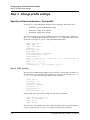
Step 3. Change profile settings .......................................................................................... 2-24
Specify card-level parameters – Card profile ............................................................. 2-24
Specify ICMP throttling ........................................................................................ 2-24
Specify different executables ................................................................................ 2-25
Specify different dump settings ........................................................................... 2-25
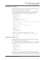
Change executables for all dev1 cards - Load profile ................................................. 2-27
Change dump defaults for all dev1 cards - Dump profile ............................................ 2-28
Dump vectors (read-only)..................................................................................... 2-29
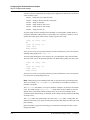
Step 4. Run dev1config to create grdev1.conf .................................................................... 2-31
Method 1: Recommended, use SP SNMP Manager .................................................... 2-31
Method 2: Optional, edit /etc/grdev1.conf................................................................... 2-31
How to run the command.............................................................................................. 2-31
Contents of /etc/grdev1.conf......................................................................................... 2-32
iv
SP Switch Router Adapter Guide - 1.4 Update 2
Contents
Parameter definitions ....................................................................................................
Step 5. Reset card to install files .........................................................................................
Saving configuration files .............................................................................................
Verify SP Switch Router Adapter card from router ...........................................................
Verify media card operation using ping ......................................................................
Verify switch node connectivity using ping .................................................................
Check media card status using grcard ..........................................................................
Media card states ...................................................................................................
Reset media card using grreset ...................................................................................
Bringing the SP Switch Router Adapter card on-line with the SP ......................................
Checking connectivity to the SP system.......................................................................
Procedure ......................................................................................................................
Chapter 3
2-33
2-35
2-35
2-36
2-36
2-37
2-37
2-37
2-38
2-40
2-40
2-41
Monitoring and Management Tools ............................................... 3-1
SP Switch Router command overview................................................................................... 3-2
csconfig .......................................................................................................................... 3-2
flashcmd.......................................................................................................................... 3-2
getver............................................................................................................................... 3-3
grarp .............................................................................................................................. 3-3
grcard ............................................................................................................................. 3-3
grfins ............................................................................................................................... 3-3
grms ............................................................................................................................... 3-4
grreset.............................................................................................................................. 3-4
grrmb ............................................................................................................................. 3-4
grroute ............................................................................................................................. 3-4
grrt................................................................................................................................... 3-4
grsite................................................................................................................................ 3-4
grsnapshot ....................................................................................................................... 3-4
grstat ............................................................................................................................... 3-5
grwrite ........................................................................................................................... 3-5
mountf ............................................................................................................................. 3-5
setver ............................................................................................................................... 3-5
umountf ........................................................................................................................... 3-5
vpurge ............................................................................................................................ 3-5
SP Switch Router UNIX tools ............................................................................................... 3-6
ping ............................................................................................................................... 3-6
route ................................................................................................................................ 3-6
tcpdump .......................................................................................................................... 3-7
traceroute ........................................................................................................................ 3-7
Using the netstat command ................................................................................................... 3-8
netstat -rn ...................................................................................................................... 3-8
netstat -rs ....................................................................................................................... 3-9
netstat -in ........................................................................................................................ 3-9
netstat -an ..................................................................................................................... 3-10
netstat -s ........................................................................................................................ 3-11
Obtaining layer 2 and 3 statistics - grstat ............................................................................. 3-12
Options.......................................................................................................................... 3-12
Layer 3 statistics ........................................................................................................... 3-12
List of IP stats ........................................................................................................ 3-12
SP Switch Router Adapter Guide - 1.4 Update 2
v
Contents
Layer 2 statistics ...........................................................................................................
List of layer 2 stats.................................................................................................
SP Switch Router Adapter card maint commands ...............................................................
Preparing to use maint commands ................................................................................
Sample maint commands ..............................................................................................
Find hardware and software version numbers - maint 2 .......................................
Find transmit (tx) binary version - maint 102........................................................
Display configuration and status - maint 3 ............................................................
maint 4 - display media statistics ..........................................................................
maint 5 - display switch statistics ..........................................................................
maint 6 - display combus statistics ........................................................................
Filtering commands - maint 50-58, 150-58 ..........................................................
List the filters per media card - maint 50 ..............................................................
List where filters are assigned - maint 54 .............................................................
Configure UDP packet discards - maint 89 7 ........................................................
Display ARP table - maint 189 1 ..........................................................................
Flush the ARP cache - maint 189 10 ....................................................................
Display switch route table - maint 189 2 ..............................................................
“Switch route not found” .......................................................................................
Checking for hardware problems - grdiag ..........................................................................
What is tested ...............................................................................................................
Where to find the user guide.........................................................................................
Stopping or halting grdiag ............................................................................................
When a media card does not boot after grdiag ............................................................
“Switch receive error” can indicate hardware problem ...............................................
SP Switch Router dumps .....................................................................................................
System dumps ...............................................................................................................
Media card dumps ........................................................................................................
Use grdinfo to collect logs ..........................................................................................
Data collection utility - grdinfo............................................................................................
Options ........................................................................................................................
SP Switch Router example............................................................................................
SP Switch Router logs ........................................................................................................
Accessing a log file.......................................................................................................
Sample gr.console log...................................................................................................
Sample gr.boot log ........................................................................................................
Sample messages log ....................................................................................................
Burning in media card flash memory...................................................................................
Appendix A
3-14
3-14
3-15
3-15
3-16
3-16
3-16
3-16
3-17
3-17
3-18
3-18
3-19
3-19
3-19
3-20
3-20
3-21
3-21
3-22
3-22
3-22
3-22
3-23
3-23
3-24
3-24
3-24
3-24
3-25
3-25
3-26
3-30
3-30
3-31
3-32
3-33
3-34
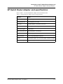
Part Numbers .................................................................................. A-1
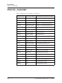
Parts list – model 04S............................................................................................................ A-1
Parts list – model 16S............................................................................................................ A-3
Publication numbers – IBM manuals.................................................................................... A-4
Appendix B
Log Messages ................................................................................. B-1
Alphabetical list of messages ................................................................................................. B-1
Message descriptions ............................................................................................................. B-3
vi
SP Switch Router Adapter Guide - 1.4 Update 2
Contents
Appendix C
Network Configuration Examples ................................................. C-1
Example 1: Single SP Switch Router Adapter card, single SP partition ....................... C-2
Configuration requirements ..................................................................................... C-2
Example 2: Multiple cards, single partition................................................................... C-3
Configuration requirements ..................................................................................... C-3
Configuration tasks.................................................................................................. C-4
Incoming traffic (going to SP processor nodes) ..................................................... C-4
Outgoing traffic (coming from SP processor nodes).............................................. C-4
Recovery procedure if an SP Switch Router Adapter card fails..................................... C-5
Example 3: Multiple cards, multiple SP partitions: ........................................................ C-6
Configuration tasks.................................................................................................. C-6
Appendix D
Upgrading Router Software ........................................................... D-1
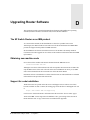
The SP Switch Router as an IBM product .....................................................................
Obtaining new machine code ........................................................................................
Support for code installation..........................................................................................
IBM License Agreement for Machine Code..................................................................
D-1
D-1
D-1
D-2
Index.......................................................................................... Index-1
SP Switch Router Adapter Guide - 1.4 Update 2
vii
Contents
viii
SP Switch Router Adapter Guide - 1.4 Update 2
Figures
Figure 1-1
Figure 1-2
Figure 1-3
Figure 1-4
Connections between the SP Switch Router and an SP system
..............
Expandable area of system memory .............................................................
Media card components ................................................................................
LEDs on the SP Switch Router Adapter card ...............................................
Figure 2-1
Figure 2-2
Figure 2-3
Figure 2-4
Figure 2-5
Components connecting an SP Switch Router to an SP Switch and control
workstation.................................................................................................... 2-2
SP system administrative Ethernet connections ......................................... 2-10
SP Switch Router Adapter cable 50-pin connector end.............................. 2-10
How frames enable connections to multiple SP Switches.......................... 2-15
Components in the SP Switch Router Adapter card’s interface name ....... 2-22
Figure 3-1
Figure 3-2
Figure 3-3
Figure 3-4
Figure 3-5
SP Switch Router control board memory components................................. 3-2
Sample entries in the gr.console log ........................................................... 3-31
Sample entries in the gr.boot log ................................................................ 3-32
Sample entries in the messages log ............................................................ 3-33
Sample entries in the gr.boot log ................................................................ 3-34
Figure C-1
Figure C-2
Figure C-3
Figure C-4
Example 1 – one card, one SP partition network configuration ................... C-2
Example 2 – multiple card, single SP partition configuration...................... C-3
Recovery from a card failure in a dually-connected configuration .............. C-5
Example 3 – multiple card, multiple SP partition configuration .................. C-6
SP Switch Router Adapter Guide - 1.4 Update 2
1-2
1-5
1-7
1-9
ix
Figures
x
SP Switch Router Adapter Guide - 1.4 Update 2
Tables
Table 1-1
Table 1-2
Table 1-3
SP Switch Router Adapter card LED activity during boot and reset............ 1-9
SP Switch Router Adapter media card LEDs ............................................. 1-11
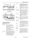
SP Switch Router Adapter media card specifications................................. 1-13
Table A-1
Table A-2
Table A-3
IBM and Lucent part numbers for model 04S ............................................ A-1
IBM and Lucent part numbers for model 16S ............................................. A-3
Publication numbers for related IBM manuals ............................................ A-4
SP Switch Router Adapter Guide - 1.4 Update 2
xi
Tables
xii
SP Switch Router Adapter Guide - 1.4 Update 2
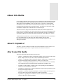
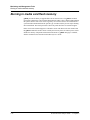
About this Guide
Lucent’s GRF switched IP routers can be used to provide high-speed data communication links
between IBM RS/6000 Scalable POWERparallel Systems (SP) and external networks/hosts.
When packaged with an IBM SP system, the GRF router is referred to as an RS/6000 SP
Switch Router, or SP Switch Router. The SP Switch Router Adapter card is the GRF media
card that specifically supports SP system data transfers. To connect to an SP system, the SP
Switch Router Adapter card is cabled directly to an SP Switch port.
The SP Switch Router Adapter Guide describes the media card itself and explains how to
install, verify, and configure the card. The Guide provides the same type of information for this
media card as is provided for other GRF media cards. Information specific to installing and
configuring a GRF router is found in the manuals listed below in the “Manual sets” section.
The RS/6000 SP Switch Router is based on the GRF 400 and GRF1600 routers manufactured
by Lucent Technologies. For that reason, this manual contains references to the
GRF 400/1600 Getting Started, GRF Reference Guide, and GRF Configuration and
Management manuals.
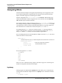
About 1.4 Update 2
The GRF 1.4 Update 2 manual set includes new features added since software release 1.4.12.
GateD information is provided in a separate document, the GRF GateD Manual.
How to use this Guide
The Guide contains the following chapters and an index:
•
Chapter 1, “Introduction to the SP Switch Router Adapter Card,” describes the SP Switch
Router Adapter media card, its cables, LEDs, and SNMP implementation.
•
Chapter 2, “Configuring the SP Switch Router Adapter,” explains how to configure the SP
Switch Router Adapter media card and how to attach it to the SP Switch.
•
Chapter 3, “Monitoring and Management Tools,” contains information about commands,
logs, and dumps useful for maintaining the SP Switch Router and adapter card.
•
Appendix A, “Part Numbers,” contains a table of corresponding Lucent and IBM part
numbers for SP Switch Router components.
•
Appendix B, “Log Messages,” contains explanations of log messages generated by the SP
Switch Router Adapter media card.
•
Appendix C, “Network Configuration Examples,” contains examples and descriptions of
three basic SP Switch network configurations and their requirements.
•
Appendix D, “Upgrading SP Switch Router Software,” describes how to install new
releases of the router’s operating software.
SP Switch Router Adapter Guide - 1.4 Update 2
October 25, 1999 xiii
About this Guide
Manual sets
Manual sets
This section provides a list of relevant GRF manuals. A second list includes IBM system
manuals that contain information specific to the SP supercomputer.
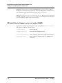
SP Switch Router manuals
The SP Switch Router Adapter media card is described only in the SP Switch Router Adapter
Guide. The SP Switch Router and other media cards are described in the GRF manual set.
The GRF 1.4 Update 2 documentation set consists of the following manuals:
•
GRF 400/1600 Getting Started - 1.4 Update 2
•
GRF Configuration and Management - 1.4 Update 2
•
GRF Reference Guide - 1.4 Update 2
•
GRF GateD Manual - 1.4 Update 2
•
SP Switch Router Adapter Guide - 1.4 Update 2
Router manuals and software upgrade release notes for the 9077 are available in PDF format
from this Web site:
http://www.rs6000.ibm.com/resource/aix_resource/sp_books/sra
/index.html
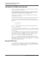
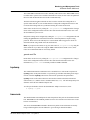
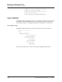
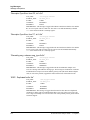
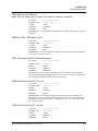
To check which software release your SP Switch Router is running, use the getver command:
super> getver
Current Revision: 1.4.20.ibm Version: default
super>
IBM SP system manuals
IBM information specific to the SP Switch Router Adapter card appears in:
xiv October 25, 1999
•
IBM RS/6000 Scalable POWERparallel Systems:
Planning, Volume 1, Hardware and Physical Environment, GA22-7280
•
IBM RS/6000 Scalable POWERparallel Systems:
Planning, Volume 2, Control Workstation and Software Environment, GA22-7281
•
IBM Parallel System Support Programs for AIX:
Installation and Migration Guide, GA22-7347
•
IBM Parallel System Support Programs for AIX:
Administration Guide, SA22-7348
•
IBM Parallel System Support Programs for AIX:
Diagnosis Guide, GA22-7350
•
IBM Parallel System Support Programs for AIX:
Command and Technical Reference, Volume 1, SA22-7351
•
IBM Parallel System Support Programs for AIX:
Command and Technical Reference, Volume 2, SA22-7351
•
IBM Parallel System Support Programs for AIX:
Messages Reference, GA22-7352
SP Switch Router Adapter Guide - 1.4 Update 2
About this Guide
Documentation conventions
You can download PDF versions of these manuals from the RS6000 SP Product
Documentation Library at this web site:
http://www.rs6000.ibm.com/resource/aix_resource/sp_books/
http://www.rs6000.ibm.com/resource/aix_resource/sp_books/pssp/inde
x.html
Documentation conventions
This manual uses the following standard documentation conventions:
Convention
Meaning
Monospace text Represents text that appears on your computer’s screen, or that could
appear on your computer’s screen.
Boldface text
Represents characters that you enter exactly as shown (unless the
characters are also in italics—see Italics, below). Command
names used in text appear in boldface.
Italics
In command usage, italic represent variable information. Do not enter
the words themselves in the command. Enter the information they
represent. In ordinary text, italics are used for titles of publications, for
some terms that would otherwise be in quotation marks, and to show
emphasis.
[]
Square brackets indicate an optional argument you might add to a
command. To include such an argument, type only the information
inside the brackets. Do not type the brackets unless they appear in bold
type.
|
Separates command choices that are mutually exclusive.
Key1-Key2
Represents a combination keystroke. To enter a combination
keystroke, press the first key and hold it down while you press one or
more other keys. Release all the keys at the same time. (For example,
Ctrl-H means hold down the Control key and press the H key.)
Press Enter
Means press the Enter, or Return, key or its equivalent on your
computer.
Note:
Introduces important additional information.
!
Caution:
Warns that a failure to follow the recommended procedure could result
in loss of data or damage to equipment.
Warning:
Warns that a failure to take appropriate safety precautions could result
in physical injury.
SP Switch Router Adapter Guide - 1.4 Update 2
October 25, 1999 xv
About this Guide
IP routing publications
IP routing publications
Here are some related publications that you may find useful:
xvi October 25, 1999
•
Internetworking with TCP/IP, Volume 1 and 2, by Douglas E. Comer, and David L.
Stevens. Prentice-Hall,
•
TCP/IP Illustrated, Volumes 1 and 2, by W. Richard Stevens. Addison-Wesley, 1994.
•
Interconnections, Radia Perlman. Addison-Wesley, 1992.
Recommended for information about routers and bridging.
•
Routing in the Internet, by Christian Huitema. Prentice Hall PTR, 1995.
Recommended for information about IP, OSPF, CIDR, IP multicast, and mobile IP.
•
TCP/IP Network Administration, by Craig Hunt. O’Reilly & Associates, Inc. 1994.
Recommended for network management information.
•
Essential System Administration, Æleen Frisch. O’Reilly & Associates, Inc. 1991.
Recommended for network management information.
SP Switch Router Adapter Guide - 1.4 Update 2
Introduction to the SP Switch Router
Adapter card
1
The RS/6000 SP Switch Router is based on the GRF 400 (4-card) and GRF 1600 (16-card)
routers manufactured by Lucent Technologies. For that reason, this manual contains references
to the GRF 400/1600 Getting Started, GRF Reference Guide, and
GRF Configuration and Management manuals. The SP model of the router is referred to as the
SP Switch Router.
SP Switch Routers can be used to provide high-speed data communication links between IBM
RS/6000 Scalable POWERparallel Systems (SP) and external networks/hosts. The SP Switch
Router Adapter card is the router media card that specifically supports SP system data
transfers. To connect to an SP system, the SP Switch Router Adapter card is cabled directly to
an SP Switch port.
Material in Chapter 1 provides a basic description of the SP Switch Router Adapter card.
Please refer to the GRF 400/1600 Getting Started manual for SP Switch Router system
installation procedures.
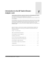
Chapter 1 covers these topics:
What is the RS/6000 SP Switch Router ? . . . . . . . . . . . . . . . . . . . . . . . . . . . . . . . . . . . 1-2
SP Switch Router systems for IBM sites . . . . . . . . . . . . . . . . . . . . . . . . . . . . . . . . . . . . 1-3
Upgrading system memory . . . . . . . . . . . . . . . . . . . . . . . . . . . . . . . . . . . . . . . . . . . . . . 1-5
Overview of the SP Switch Router Adapter card. . . . . . . . . . . . . . . . . . . . . . . . . . . . . . 1-6
Inserting a media card into the SP Switch Router . . . . . . . . . . . . . . . . . . . . . . . . . . . . . 1-7
SP Switch Router Adapter card LEDs . . . . . . . . . . . . . . . . . . . . . . . . . . . . . . . . . . . . . . 1-9
SP Switch Router Adapter card specifications . . . . . . . . . . . . . . . . . . . . . . . . . . . . . . . 1-13
Assigning filters . . . . . . . . . . . . . . . . . . . . . . . . . . . . . . . . . . . . . . . . . . . . . . . . . . . . . . 1-14
SNMP on the SP Switch Router Adapter card . . . . . . . . . . . . . . . . . . . . . . . . . . . . . . . 1-15
SP Switch Router Adapter Guide - 1.4 Update 2
October 22, 1999 1-1
Introduction to the SP Switch Router Adapter card
What is the RS/6000 SP Switch Router ?
What is the RS/6000 SP Switch Router ?
The RS/6000 SP Switch Router is a high-performance switched IP router designed for
high-volume, large-scale public and private backbone applications.
It has these main features:
•
Performs Layer-3 switching across 4-16 adapter slots, depending upon router model
•
Supports large suite of dynamic routing protocols
•
Accommodates multiple types of media, including HSSI, 10/100Base-T (fast Ethernet),
ATM OC-3c, ATM OC-12c, SONET OC-3c, HIPPI, and FDDI
•
Provides basic filtering, OSPF multicast, SNMP v1
•
Manages 150K-entry route table, batch updating with 20 routes per second
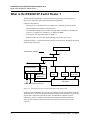
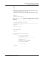
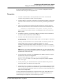
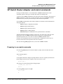
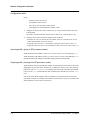
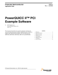
As shown in Figure 1-1, the SP Switch Router attaches to the SP Switch through the SP Switch
Router Adapter media card:
SP control workstation
Administrative network =
Ethernet hub or bridge
SP Switch Router
control
board
Switch
•••
SP Switch
Router Adapter
media card
Processor
node
•••
Processor
node
Primary node
for SP Switch
SP Switch
to/from other networks and hosts
Figure 1-1. Connections between the SP Switch Router and an SP system
Configured with an IBM SP system, the SP Switch Router provides multiple media LAN and
WAN connectivity for the SP. The SP Switch Router Adapter card connects directly to the SP
Switch. Other components communicate across the administrative Ethernet network.
(While using a hub or a bridge to interconnect the administrative Ethernet segments is
common, other network components can be used to provide connectivity between the
segments.)
1-2 October 22, 1999
SP Switch Router Adapter Guide - 1.4 Update 2
Introduction to the SP Switch Router Adapter card
SP Switch Router systems for IBM sites
By using the appropriate SP Switch Router Adapter card, the SP system can connect to FDDI,
fast Ethernet, HSSI, ATM OC-3c, ATM OC-12c, SONET OC-3c, and HIPPI networks and
hosts, depending upon which other media cards are installed in the SP Switch Router chassis.
The SP Switch Router supports these connection options:
–
a single SP Switch Router Adapter card can be installed in an SP Switch Router
–
multiple SP Switch Router Adapter cards can be installed in an SP Switch Router
–
more than one card can connect to the same SP system
–
a single SP Switch Router can connect to one or multiple SP systems
Each option requires unique IP addressing and network configuration. Appendix C contains
examples of specific SP system–SP Switch Router networks. See the IBM documentation
related to planning for the SP Switch Router for more information.
SP Switch Router systems for IBM sites
The SP Switch Router Adapter media card communicates directly with the SP. In the SP
system configuration, the SP Switch Router Adapter media card is treated as a dependent node
and is assigned a node number. There is only one node number address space in the SP system,
and traditional SP nodes and dependent nodes are both assigned node numbers from that
address space.
You may be given references to models 9076 and 9077:
–
Model 9076 is the IBM SP system.
–
Model 9077 04S is the 4-card SP Switch Router.
–
Model 9077 16S is the 16-card SP Switch Router.
This manual uses SP system and SP Switch Router, respectively, as system names.
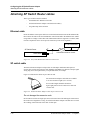
Cables included in your system
SP Switch cable
The SP Switch Router Adapter media card connects to an SP Switch via an SP Switch cable.
Make sure the shipping box contains one ten- or twenty-meter cable for each SP Switch Router
Adapter card you receive. If there is no cable, contact your IBM representative and order the
special cable required by the SP Switch Router Adapter media card from IBM:
•
SP Switch cable, 10m (IBM P/N 46H9699)
•
SP Switch cable, 20m (IBM P/N 46H9701)
Although it has 50-pin connector ends, the specified cable has custom signal wiring so that
other 50-pin cables cannot be substituted.
SP Switch Router Adapter Guide - 1.4 Update 2
October 22, 1999 1-3
Introduction to the SP Switch Router Adapter card
SP Switch Router systems for IBM sites
Ethernet cable
An Ethernet 10/100Base-T cable is required for connecting the SP Switch Router to the SP
control workstation. It is the customer's responsibility to provide the appropriate cable to make
this connection as well as any Ethernet hubs or bridges that may be required to connect to the
SP LAN.
SP ground strap
A ground strap is included with the SP Switch Router and must be connected between the
designated site on the SP Switch Router chassis and an SP frame. Refer to “ESD requirements”
on page 1-8 for a diagram showing the location of router ground strap connections.
PCMCIA 520MB disk
The SP Switch Router shipping box also contains a PCMCIA 520MB spinning disk device.
The PCMCIA disk installs in the SP Switch Router’s control board, in the PCMCIA “A” slot.
Once installed, the SP Switch Router can be configured to log and dump locally to the 520MB
external storage device.
By default, logging is turned off when the SP Switch Router boots and comes up. After the
system comes up, one of the first tasks is to configure the PCMCIA disk. The configuration
procedure formats and mounts the external PCMCIA device, and places the required logging
pointers. The installation procedure is described in Chapter 2.
Redundant AC power supplies
The SP Switch Router you receive is installed with redundant AC power supplies. You must
plug the power supply cords directly into an AC wall or rack receptacle.
Note: The SP Switch Router has no power on/off switch.
When you plug the power supply cord into a live outlet, the SP Switch Router powers on and,
since the software is already loaded, immediately begins to boot.
Redundant supply safety
Please note the following when powering off (unplugging) the SP Switch Router unit:
Caution: This unit has two power supply cords. For total isolation from electrical shock and
energy hazard, disconnect both supply cords. Care must be taken to correctly connect each
power supply to separate AC power sources and (optional) UPS devices.
Vorsicht: Dieses Gerät hat zwei Netzanschlusskabel. Um das Gerät vollstandig von Netz zu
trennen ziehen Sie beide Kabel ab, sonst können Sie einen elektrischen Schlag erhalten.
Achten Sie darauf, daß jedes Stromkabel mit einer separaten Wechselstromquelle und einem
separaten USV-Gerät verbunden wird.
Attention: Cet appareil a deux cordons d’alimentation électrique. Pour une isolation
complète de tout choc électrique et de danger énergétique, débrancher les deux cordons
d’alimentation.
1-4 October 22, 1999
SP Switch Router Adapter Guide - 1.4 Update 2
Introduction to the SP Switch Router Adapter card
Upgrading system memory
Upgrading system memory
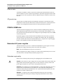
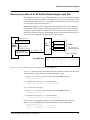
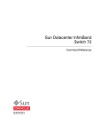
Figure 1-2 shows the area of system memory (control board RAM) that can be expanded to
meet site requirements. Memory upgrades are made in 128MB increments up to 512MB.
128MB RAM
32MB
(fixed size)
Memory
size and
organization
expandable to --> 256MB
RAM
--> 384MB
RAM
--> 512MB
RAM
- system software
- config files
- GateD binary
- log files
468MB
340MB
212MB
84MB
8-12MB
(fixed size)
- route tables
- ATMP tunnels
- kernel runs
- GateD runs
= expandable area of RAM
Figure 1-2. Expandable area of system memory
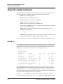
This chart provides general guidelines for memory required in different routing environments.
Although the figures assume BGP peers with 50K route entries, additional memory may be
required for higher average numbers of routes per BGP peer.
If the SP Switch Router is to support dynamic routing or ATMP home agents and mobile
nodes, upgrade to at least 256MB. In environments where large numbers of routes are
advertised, upgrade to 512MB.
Customer
profile
Amount of
control
board
memory
needed
Space for
dynamic
routing,
ATMP
tables
Route
entries
on
media
card
Route
entries in
dynamic
routing
database
Static routing:
(in high-performance
environment)
128MB
84MB
150K
Typical
number:
35,800
0
Small POP
256MB
212MB
150K
Typical
number:
199,000
3
Medium POP /
ISP backbone
384MB
340MB
150K
Typical
number:
362,000
9
Large POP /
Exchange point /
Route reflection server
512MB
468MB
150K
Typical
number:
521,000
12
SP Switch Router Adapter Guide - 1.4 Update 2
Typical
numbe
r of
peer
sessions
October 22, 1999 1-5
Introduction to the SP Switch Router Adapter card
Overview of the SP Switch Router Adapter card
Overview of the SP Switch Router Adapter card
The SP Switch Router Adapter media card is cabled to a connector jack on an SP Switch. This
media card transfers data to/from the SP Switch at 100 MB/s in each direction.
Like other SP Switch Router media interfaces, the SP Switch Router Adapter media card:
–
is intelligent, and performs IP-level routing and route look-ups
–
provides complete speed-decoupling between the connecting media and the
gigabit/second router switch core
–
fully buffers data for input and output queuing; each card has 16MB of high-speed
receive buffer memory and 16MB of high-speed transmit buffers
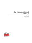
Face plate diagram
The SP Switch Router Adapter card provides one
full-duplex interface.
This illustration shows the faceplate, the interface
connector, and the card LEDs.
The actual height of the SP Switch Router Adapter card is
10 inches.
PWR ON
3V
RX HB
RX ST0
RX ST1
RX ERR
MD RCV
SW XMIT
The SP Switch Router Adapter cable 50-pin
connector end is also shown.
TX HB
TX ST0
TX ST1
TX ERR
MD XMIT
SW RCV
1-6 October 22, 1999
SP Switch Router Adapter Guide - 1.4 Update 2
Introduction to the SP Switch Router Adapter card
Inserting a media card into the SP Switch Router
Inserting a media card into the SP Switch Router
Note:
To operate properly, the 16-card SP Switch Router requires that at least two media cards be
installed. The 4-card router requires one card be installed. In both models, a face plate cover
must be installed in any unused chassis slot to maintain router cooling flows.
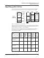
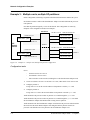
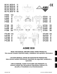
Media cards are actually two logic boards joined to make a single component. As shown in
Figure 1-3, the smaller board on the right is the serial interface, also called the serial daughter
card. The larger one on the left is the media board and has the network ports. Together they
comprise an SP Switch Router media card.
Cards install vertically for 16-card SP Switch Router:
Media board
Serial
daughter
Port
card
Serial/rev
number area
Cards install horizontally level for 4-card SP Switch Router:
Top
Bottom
Figure 1-3. Media card components
The two logic boards are joined by a pair of 100-pin connectors and reinforcing plates. Even
so, this joint retains some flex and must be carefully supported, especially when inserting the
media card into the chassis.
Warning: The backplane of the SP Switch Router contains hazardous energy levels. When
replacing a media card, remove only one card at a time. Removing more than one card will
expose the operator to this energy hazard.
Warnung: An den Rückwandplatinen der SP Switch Router liegen gefährliche
Hochspannungen ab. Zum Auswechseln der Medienkarte jeweils nur eine Karte entfernen. Bei
zwei gleichzeitig entfernten Karten ist der Bediener gefährlichen Spannungen ausgesetzt.
SP Switch Router Adapter Guide - 1.4 Update 2
October 22, 1999 1-7
Introduction to the SP Switch Router Adapter card
Inserting a media card into the SP Switch Router
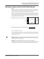
ESD requirements
!
Caution: Media cards are hot swappable and can be installed when the SP Switch Router is
running. However, media cards are highly susceptible to damage from electrostatic discharge.
You must wear a grounded, conductive wrist strap any time you handle a media card. Make
sure the metallic elements in the band directly touch your exposed skin.
SP Switch Router - 4 card
SP Switch Router - 16 card
Wrist strap grounding sites
Card insertion procedure
1
When you are properly grounded, remove the media card from its anti-static container.
2
Hold the media card with the network ports facing you.
4-card router
Turn the card horizontal, the top of the media card should be on the left, the bottom of the
card should be on the right. As you start, make sure you visually identify the left and right
guide pair for this particular slot.
Keeping the media card horizontally level, insert the card fully into the slot, you will feel
the card joining with the 100-pin connector on the backplane.
16-card router
Hold the card vertically. As you start, make sure you visually identify the top and bottom
guide pair for this particular slot. Have one hand under the card, lightly supporting its
weight. Rest just the edge of the bottom corner of the card in the bottom guide. Then,
bring the top edge of the card into the top guide. This will help you keep the card level as
you slide it in.
Keeping the media card vertically upright, insert the card fully into the slot.
You will feel the card joining with the 100-pin connector on the backplane.
3
When fully inserted, the card’s face plate should be flush against the chassis back panel.
Note: Do not force the card into the slot. Doing so can damage the card or slot connector.
4
1-8 October 22, 1999
Tighten the screws at each end of the face plate.
SP Switch Router Adapter Guide - 1.4 Update 2
Introduction to the SP Switch Router Adapter card
SP Switch Router Adapter card LEDs
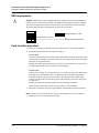
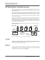
SP Switch Router Adapter card LEDs
The “RX” and “TX” LEDs are under software control and indicate port states on receive and
transmit sides. The “MD” and “SW” LEDs are hardware-controlled and reflect data activity on
the SP Switch Router switch core or interface side of receive and transmit ports.
MD XMIT
SW RCV
TX HB
TX ST0
TX ST1
TX ERR
MD RCV
SW XMIT
“Bottom” end of card
RX HB
RX ST0
RX ST1
RX ERR
PWR ON
3V
“Top” end of card
Figure 1-4. LEDs on the SP Switch Router Adapter card
LED activity during boot
During boot and resets, the four software-controlled LEDs indicate different media card
activities by flashing in specific patterns. Refer to Table 1-1 for a description of each pattern.
Table 1-1. SP Switch Router Adapter card LED activity during boot and reset
LED
Description
• RX HB (green)
•
•
•
•
ON
ON
ON
ON
At reset, all LEDs are lit for 1/2 second
as part of on-board diagnostics.
Also tests that LEDs are working.
•
•
•
•
OFF
OFF
OFF
ON
ERROR
- During a boot or reset, this pattern indicates
a checksum error is detected in
flash memory.
•
•
•
•
ON
OFF
ON
OFF
ERROR
- During a boot or reset, this pattern indicates
that the SRAM fails the memory test.
•
•
•
•
ON -> OFF
OFF
OFF
ON -> OFF
• RX ST0 (green)
• RX ST1 (amber)
• RX ERR (amber)
SP Switch Router Adapter Guide - 1.4 Update 2
- During loading, HB and RX ST1 flash
as each section of the code loads.
October 22, 1999 1-9
Introduction to the SP Switch Router Adapter card
SP Switch Router Adapter card LEDs
Table 1-1. SP Switch Router Adapter card LED activity during boot and reset
LED
Description
• TX HB (green)
•
•
•
•
ON
ON
ON
ON
At reset, all LEDs are lit for 1/2 second
as part of on-board diagnostics.
Also tests that LEDs are working.
•
•
•
•
OFF
OFF
OFF
ON
ERROR
- During a boot or reset, this pattern indicates
a checksum error is detected in
flash memory.
•
•
•
•
ON
OFF
ON
OFF
ERROR
- During a boot or reset, this pattern indicates
that the SRAM fails the memory test.
•
•
•
•
ON -> OFF
OFF
OFF
ON -> OFF
• TX ST0 (green)
• TX ST1 (amber)
• TX ERR (amber)
1-10 October 22, 1999
(continued)
- During loading, HB and TX ST1 flash
as each section of the code loads.
SP Switch Router Adapter Guide - 1.4 Update 2
Introduction to the SP Switch Router Adapter card
SP Switch Router Adapter card LEDs
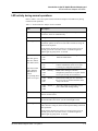
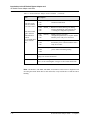
LED activity during normal operations
Refer to Table 1-2 for a description of SP Switch Router Adapter card LED activity during
normal run time operations.
Table 1-2. SP Switch Router Adapter media card LEDs
LED
Description
PWR ON
This green LED is on when 5 volts are present. Both power LEDs,
5V and 3V, can be on simultaneously.
3V
This green LED is on when 3 volts are present.
RX HB (green)
During normal run-time operations, this green LED blinks a
“heartbeat” pattern for the receive side CPU. The beat is a long off,
short on-off-on pattern .
In the pattern, the LED goes off for 1/2 second, comes on for 1/4
second, goes off for 1/4, comes on for 1/4, and then begins the
pattern again by going off for 1/2 second.
• RX ST0 (green)
• RX ST1 (amber)
• RX ERR (amber)
These three LEDs
light in different
combinations to
indicate
five operating states
for the receive port.
• ON
• ON
• ON
STATE_0
- These three LEDs are on during
hardware initialization.
• OFF
• ON
• ON
STATE_1 - Bottom two amber LEDs go on during
software initialization, show receive port
is waiting for configuration parameters.
• ON
• OFF
• ON
STATE_2 - Middle amber LED goes off when
configuration parameters are in place and the
receive port is ready to be connected.
• OFF
• OFF
• ON
STATE_3 - Bottom amber LED goes on to show that
the receive port is connected and the card is
ready to be on line
• OFF
• OFF
• OFF
STATE_4 - These three LEDs are off to show receive
port is online and running/routing.
MD RCV (amber)
This amber LED lights when data comes into the receive media port
from an external source.
SW XMIT (amber)
This amber LED lights when the receive media port sends data to the
SP Switch Router switch core (via the serial daughter card).
TX HB (green)
This green LED blinks a “heartbeat” pattern for the transmit side
CPU, the beat is a long off, short on-off-on pattern during normal run
time operations.
In the pattern, the LED goes off for 1/2 second, comes on for 1/4
second, goes off for 1/4, comes on for 1/4, and then begins the
pattern again by going off for 1/2 second.
SP Switch Router Adapter Guide - 1.4 Update 2
October 22, 1999 1-11
Introduction to the SP Switch Router Adapter card
SP Switch Router Adapter card LEDs
Table 1-2. SP Switch Router Adapter media card LEDs
LED
• TX ST0 (green)
• TX ST1 (amber)
• TX ERR (amber)
These three LEDs
light in different
combinations to
indicate
five operating states
for the transmit
port.
(continued)
Description
• ON
• ON
• ON
STATE_0
- These three LEDs are on during
hardware initialization.
• OFF
• ON
• ON
STATE_1 - Bottom two LEDs (amber) go on during
software initialization, show transmit port
is waiting for configuration parameters
• ON
• OFF
• ON
STATE_2 - Middle LED goes off when
configuration parameters are in place and the
transmit port is ready to be connected.
• OFF
• OFF
• ON
STATE_3 - Bottom LED (amber) goes on to show that
the transmit port is connected and the card is
ready to be on line.
• OFF
• OFF
• OFF
STATE_4 - These three LEDs are off to show transmit
port is online and running/routing.
MD XMIT (amber)
This amber LED comes on as data leaves the transmit media side
going to an external destination.
SW RCV (amber)
This amber LED lights when data from the SP Switch Router switch
core (via the serial daughter card) goes to the transmit media side.
Note: The MD RCV, SW XMIT, MD XMIT, and SW RCV LEDs increase in brightness with
increasing data traffic. When there is little data traffic, it may be difficult to see that the LED is
blinking.
1-12 October 22, 1999
SP Switch Router Adapter Guide - 1.4 Update 2
Introduction to the SP Switch Router Adapter card
SP Switch Router Adapter card specifications
SP Switch Router Adapter card specifications
Refer to Table 1-3 for SP Switch Router Adapter media card characteristics:
Table 1-3. SP Switch Router Adapter media card specifications
Element
Value
Attachment density
One full-duplex interface
Media transfer rate
100 megabytes per second
Processors
40 MHz SPARC, one transmit, one receive
Data buffers
16MB input, 16MB output
Route table support
150K entries
Max transmission unit
The default MTU is 65520 bytes
Card connector
2-row, 50-pin panel-mount receptacle
Cable connector
2-row, 50-pin shielded tab connector
Cables
Twisted-pair copper, 10- or 20-meter length, available from IBM
Power consumption
Approximately 50 watts per media card
SP Switch Router Adapter Guide - 1.4 Update 2
October 22, 1999 1-13
Introduction to the SP Switch Router Adapter card
Assigning filters
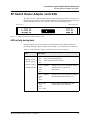
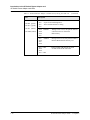
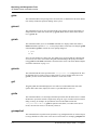
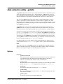
Assigning filters
The SP Switch Router Adapter card supports IP packet filtering. You can apply filters to the
receive and/or transmit path of a logical interface as described in the “IP Packet Filtering”
chapter of the GRF Configuration and Management manual.
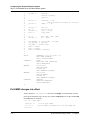
The filter configuration file is /etc/filterd.conf. The maint 50 – 58 commands report
statistics and information for filters assigned to the receive side of the card. The maint 150 –
158 commands report on transmit side filters.
The “IP Packet Filtering” chapter describes the entries in /etc/filterd.conf and tells you
how to design several types of filters. The binding statement in /etc/filterd.conf is where
you assign a filter you have created to a particular logical interface on a specific media card.
This statement has two variables that are media card specific, media and vlif.
In a binding statement, media is the type of media card and vlif is the logical interface
number to which the filter is assigned. For the SP Switch Router Adapter card, media is
always dev1 and the vlif is always 0 since the card has a single interface.
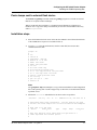
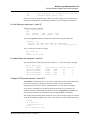
Here is a binding statement for an SP Switch Router Adapter card in slot 5, gt050 (the card is
connected to node 8 on an SP switch):
media dev1 5 {
# the filter named “no_host_22” blocks all packets from remote host 192.168.22.22
bind no_host_22_22 {
vlif 0;
direction out;
action filter;
# this is the switch node 8 interface
# outbound traffic to node 8
}
}
Here are the supported media names:
atm (OC-3c)
dev1
ether
fddi
hssi
hippi
sonet (OC-3c)
Please refer to the “IP Packet Filtering” chapter of the GRF Configuration and Management
manual for configuration information and examples.
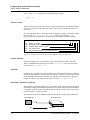
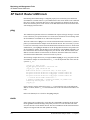
tcpdump
Filtering supports the standard UNIX tcpdump utility that enables you to examine the data
crossing an SP Switch Router Adapter interface. A tcpdump “listen” command for interface
gt030 is:
# tcpdump -i gt030
1-14 October 22, 1999
SP Switch Router Adapter Guide - 1.4 Update 2
Introduction to the SP Switch Router Adapter card
SNMP on the SP Switch Router Adapter card
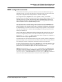
SNMP on the SP Switch Router Adapter card
This section describes the SNMP implementation on the SP Switch Router Adapter card as a
way of providing information for staff supporting the card from the SP control workstation.
Chapter 2 describes the actual configuration procedure performed on the SP Switch Router.
Although the mib2d daemon within the SP Switch Router supports several MIBs, the SET
command is supported only for the SP Switch Router Adapter card MIB, ibmSPDepNode.
For SP Switch Router Adapter cards specifically, mib2d creates a table of
ibmSPDepNodeEntry MIB objects, one entry for each possible media card slot.
SNMP write access mode is supported for SP Switch Router Adapter configuration parameters
and for an object representing the Administrative state of the adapter.
When a SET command is received for an object defined in the ibmSPDepNode MIB, the
/etc/grdev1.conf configuration file is also updated with the newly-set value. The SP
Switch Router Adapter card’s run-time software reports board status to mib2d.
For more information about the use of SNMP to configure the SP Switch Router Adapter card,
please refer to the “Managing Extension Nodes” chapter in the PSSP Administration Guide.
SP Switch Router Adapter dependent node MIB support
SP Switch Router Adapter MIB support complies with the dependent node MIB definition and
provides these objects:
–
ibmSPDepNode
–
ibmSPDepNodeTable
–
ibmSPDepNodeEntry
–
ibmSPDepNodeName
–
ibmSPDepNodeNumber
–
ibmSPDepSwToken
–
ibmSPDepSwARP
–
ibmSPDepSwNodeNumber
–
ibmSPDepIPaddr
–
ibmSPDepNetMask
–
ibmSPDepIPMaxLinkPkt
–
ibmSPDepIPHostOffset
–
ibmSPDepConfigState
–
ibmSPDepSysName
–
ibmSPDepNodeState
–
ibmSPDepSwChipLink
–
ibmSPDepNodeDelay
–
ibmSPDepAdminStatus
SP Switch Router Adapter Guide - 1.4 Update 2
October 22, 1999 1-15
Introduction to the SP Switch Router Adapter card
SNMP on the SP Switch Router Adapter card
The object ibmSPDepNodeName serves as an index for the ibmSPDepNodeTable and is
initialized to a constant text string equivalent to the corresponding chassis slot number: 00–15.
The slot numbers support SP Switch Router chassis with 4 or 16 card slots.
The objects ibmSPDepConfigState, ibmSPDepNodeState, and ibmSPDepNodeName are
read-only. At start up, ibmSPDepConfigState is set to 1 (not-configured), and is changed as
the SP Switch Router Adapter media card state changes.
SP Switch Router Adapter media card states (SNMP)
These states are available as possible instance values for the SNMP ibmSPDepConfigState
object, but are not directly viewed by the user:
1 - notConfigured
(card is initialized)
4 - diagnosticFailed
(card’s own on-board diagnostics fail)
5 - microcodeLoadFailed
(card is waiting for valid, not null, configuration parameters)
6 - fullyConfigured
(card is initialized, configured, ready to be brought on line
with the SP)
1-16 October 22, 1999
SP Switch Router Adapter Guide - 1.4 Update 2
Introduction to the SP Switch Router Adapter card
SNMP on the SP Switch Router Adapter card
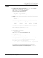
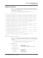
SNMP configuration overview
After the SP Switch Router is powered on and booted, the network administrator logs on to
configure the router as a system. The following is a description of the steps that can be taken
during router configuration. The actual procedure is described in Chapter 2.
The configuration for the snmpd daemon must be updated to identify the SP SNMP
Manager(s) that will configure and maintain status of the SP Switch Router Adapter card. The
community name to be used for communications with the SP SNMP Manager must be the
same community name that is specified in the Extension Node configuration data on the SP
control workstation where the SP SNMP Manager resides.
If no community name is specified on the SP control workstation, specify spenmgmt as the
community name for the SP SNMP Manager. The community name must allow read, write,
and trap capabilities. All community names used to communicate with managers other than the
SP SNMP Manager(s) should be restricted to read-only and trap capabilities. Traps should be
sent to the same UDP port on which the SP SNMP Manager is listening. This port will most
often be port number 162.
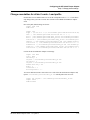
Using a UNIX editor, the administrator edits the configuration files required for each type of
media card. Configuration parameters for the SP Switch Router Adapter card could also be
entered in the /etc/grdev1.conf file at this time if the card is not going to be configured via
SNMP. Save this file using the grwrite command.
The administrator now resets the SP Switch Router system to actually install the configuration
parameters. During a reset, system daemons restart and reread their files. The media cards also
boot, loading their software, configuration information, and the current route table.
Each time the SP Switch Router software boots, mib2d starts up. Unless the administrator has
already entered SP Switch Router Adapter configuration values in /etc/grdev1.conf, file
parameters for SP Switch Router Adapter cards will all contain null values.
mib2d generates and sends a coldStart/warmStart trap message to all SNMP Managers
configured. It creates and initializes its MIB object instances. To support SET commands for
any instances of the SP Switch Router Adapter configuration objects, mib2d creates an
ibmSPDepNodeTable . The table contains an ibmSPDepNodeEntry MIB entry (there are 16
of these) for each available media card slot in various SP Switch Router models.
SP Switch Router Adapter Guide - 1.4 Update 2
October 22, 1999 1-17
Introduction to the SP Switch Router Adapter card
SNMP on the SP Switch Router Adapter card
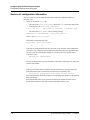
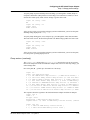
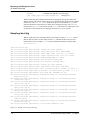
SNMP activity during media card start up
After the SP Switch Router software boots, the media cards boot and load their boot
diagnostics. The SP Switch Router Adapter media card runs its diagnostics as a check for
hardware defects. If no failure is detected, the card’s run-time software is loaded. The screen
displays diagnostic and boot reports from all the media cards, interleaved as received.
If a hardware problem is found, the diagnostic forwards a ConfigState trap request to
mib2d. In turn, mib2d sends a switchConfigState trap message
(with ConfigState=diagnosticFailed) to the SP SNMP Manager. The SP Switch Router
Adapter card continues to execute its self-test software until the card is powered off (removed
from the chassis).
Note: The execution of diagnostics at boot time is an option. The default is for diagnostics to
run each time the SP Switch Router Adapter card boots.
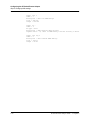
After an SP Switch Router Adapter card successfully loads its run-time software, the card
requests its configuration parameters. After the run-time software verifies the parameters are
valid (not null), the card is ready to begin normal operation.
If the configuration parameters contain null values, the card informs mib2d that the
configuration parameters have not been sent via a trap request message. mib2d sends the SP
SNMP Manager a switchConfigState trap message
(ConfigState=microcodeLoadFailed) and also a switchInfoNeeded trap message.
The card remains in this state (5, microcodeLoadFailed) until it receives valid configuration
parameters, or until the card is reset. The card periodically requests configuration parameters
and sends trap request messages to mib2d.
If the SP SNMP Manager is configured and operational, it responds to the mib2d trap
messages by sending SET commands to put the parameters in place. If the SP SNMP Manager
does not respond, there may be a configuration error that can be detected using the procedures
for diagnosing dependent node configuration problems in the PSSP Diagnosis Guide.
As a last resort, the network administrator can perform the following operations to install the
updated parameters on the SP Switch Router Adapter card:
–
run the dev1config command
–
edit /etc/grdev1.conf as required
–
use grreset slot to reset the SP Switch Router Adapter media card
The SP Switch Router Adapter card can receive valid parameters either way. It does not begin
normal operation until it is brought on line with the SP system as the IP router interface.
Refer to the section in Chapter 2 on “Bringing the SP Switch Router Adapter card on-line with
the SP” for a continuation of the start up scenario discussed here.
1-18 October 22, 1999
SP Switch Router Adapter Guide - 1.4 Update 2
Configuring the SP Switch Router Adapter
2
This chapter describes configuration and installation tasks required to connect an SP Switch
Router Adapter media card to an IBM SP System.
The RS/6000 SP Switch Router is based on the GRF 400 and GRF1600 routers manufactured
by Lucent Technologies. For that reason, this manual contains references to the
GRF 400/1600 Getting Started, GRF Reference Guide, and GRF Configuration and
Management manuals. The SP model of a GRF router is referred to as the SP Switch Router.
For more information about configuration as related to the SP, see the PSSP Administration
Guide and the PSSP Command and Technical Reference. For additional information on
troubleshooting your configuration, see the PSSP Diagnosis Guide.
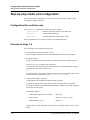
Chapter 2 covers these topics:
Introduction to installation and configuration . . . . . . . . . . . . . . . . . . . . . . . . . . . . . . . . 2-2
Installing an SP Switch Router Adapter card. . . . . . . . . . . . . . . . . . . . . . . . . . . . . . . . . 2-5
Installing the PCMCIA spinning disk . . . . . . . . . . . . . . . . . . . . . . . . . . . . . . . . . . . . . . 2-6
Attaching SP Switch Router cables . . . . . . . . . . . . . . . . . . . . . . . . . . . . . . . . . . . . . . . 2-10
Configuration required on the SP system. . . . . . . . . . . . . . . . . . . . . . . . . . . . . . . . . . . 2-12
Step-by-step media card configuration. . . . . . . . . . . . . . . . . . . . . . . . . . . . . . . . . . . . . 2-16
Step 1. Check SNMP in the SP Switch Router system . . . . . . . . . . . . . . . . . . . . . . . . 2-18
Step 2. Assign IP addresses . . . . . . . . . . . . . . . . . . . . . . . . . . . . . . . . . . . . . . . . . . . . . 2-21
Step 3. Change profile settings. . . . . . . . . . . . . . . . . . . . . . . . . . . . . . . . . . . . . . . . . . . 2-24
Step 4. Run dev1config to create grdev1.conf . . . . . . . . . . . . . . . . . . . . . . . . . . . . . . . 2-31
Step 5. Reset card to install files . . . . . . . . . . . . . . . . . . . . . . . . . . . . . . . . . . . . . . . . . 2-35
Verify SP Switch Router Adapter card from router . . . . . . . . . . . . . . . . . . . . . . . . . . . 2-36
Bringing the SP Switch Router Adapter card on-line with the SP. . . . . . . . . . . . . . . . 2-40
SP Switch Router Adapter Guide - 1.4 Update 2
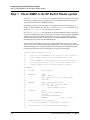
October 22, 1999 2-1
Configuring the SP Switch Router Adapter
Introduction to installation and configuration
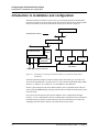
Introduction to installation and configuration
The SP Switch Router functions as an IP router to provide high-speed data communication
links between SP processor nodes and external networks/hosts. The SP Switch Router Adapter
media card connects to the SP Switch board in an SP system as shown in Figure 2-1.
SP control workstation
Administrative network =
Ethernet hub or bridge
SP Switch Router
control
board
Switch
•••
SP Switch
Router Adapter
media card
Processor
node
•••
Processor
node
Primary node
for SP Switch
SP Switch
to/from other networks and hosts
Figure 2-1. Components connecting an SP Switch Router to an SP Switch and control
workstation
The SP Switch Router Adapter card also transmits data to/from other types of media cards
across the SP Switch Router’s internal switch core. These media include HIPPI, HSSI, FDDI,
ATM OC-3c, ATM OC-12c, SONET OC-3c, and 100Base-T (Fast Ethernet).
The SP system manages the SP Switch Router Adapter card as a dependent node, under the
control of the SP SNMP Manager running on the SP control workstation and the primary node
of the SP Switch.
Once powered on and started up, the SP Switch Router can be configured and managed
remotely, via a site’s administrative network, including Telnet from the SP control workstation.
Information about procedures performed from the SP control workstation are found in the
“Managing Extension Nodes” chapter in the PSSP Administration Guide.
2-2 October 22, 1999
SP Switch Router Adapter Guide - 1.4 Update 2
Configuring the SP Switch Router Adapter
Introduction to installation and configuration
Location of relevant information
The intent of this chapter is to either provide or refer you to the necessary information to
enable you to attach an SP Switch Router to an IBM SP system, including:
•
Information to physically connect the two independent systems across cables is complete
in this chapter.
•
Information to start up, configure, and begin operations on the SP Switch Router is
contained in the GRF 400/1600 Getting Started manual.
•
Information to configure the SP Switch Router Adapter card as required for SP Switch
Router functionality is complete in this chapter.
•
Information to configure the SP Switch Router Adapter card as required for SP system
functionality is only partially described in this chapter. Detailed information is contained
in the “Managing Extension Nodes” chapter in the PSSP Administration Guide.
Pre-installation assumptions
The presentation of information in this chapter assumes the following:
•
The SP Switch Router is powered on and has a VT-100 terminal or administrative Ethernet
network connected to its control board.
•
The SP Switch Router’s basic system parameters, primarily IP address and host name,
have been configured during the first time power-on configuration script.
You use the terminal or network to log in to the SP Switch Router system and enter those
basic configuration parameters. Procedures for starting and setting up the SP Switch
Router are found in the GRF 400/1600 Getting Started manual.
•
Remote Telnet access is enabled. This requires editing the /etc/ttys file and creating an
entry for each remote session needed. Refer to Chapter 2 in the GRF Configuration and
Management manual.
Use the following command when telneting to the SP Switch Router from an X terminal:
xterm -sb -e tn <hostname_of_SP_Switch_Router>
This command ensures the screen output of the SP Switch Router is displayed correctly.
•
The SP Switch Router’s operating parameters, such as SNMP and IP addressing, have
been configured and the system rebooted so it is up and operating. Procedures to configure
operating parameters are found in the GRF Configuration and Management manual,
Chapter 2.
Descriptions of configuration and system management commands you may need are
found in the GRF Reference Guide.
•
You are ready to configure media cards. Procedures to configure media cards other than
the SP Switch Router Adapter card are found in the GRF Configuration and Management
manual
•
The IBM SP system is up and operating.
•
The SP system administrator has given you one of these pieces of information:
–
the node number assigned to each SP Switch Router Adapter card to be attached to an
SP Switch port
or
–
the port location on each SP Switch reserved for specific SP Switch Router Adapter
cards
SP Switch Router Adapter Guide - 1.4 Update 2
October 22, 1999 2-3
Configuring the SP Switch Router Adapter
Introduction to installation and configuration
Order of information
Here is the order in which installation information is presented:
2-4 October 22, 1999
–
an installation overview of tasks involving the SP Switch Router, the SP Switch
Router Adapter card, and the SP system
–
the configuration procedure for the PCMCIA 520MB disk, which also initiates
system logging
–
a description of which cables to attach between the SP Switch Router and the SP
control workstation, and between the SP Switch Router Adapter card and the SP
Switch
–
methods to determine node number and SP Switch port for an SP Switch Router
Adapter card
–
a step-by-step configuration of an SP Switch Router Adapter card
–
a list of ways to verify that the SP Switch Router Adapter card is correctly installed in
the SP Switch Router
–
a description of what needs to occur to bring the card on-line with the SP system
SP Switch Router Adapter Guide - 1.4 Update 2
Configuring the SP Switch Router Adapter
Installing an SP Switch Router Adapter card
Installing an SP Switch Router Adapter card
This section contains the procedure for physical installation and minimal configuration of the
SP Switch Router Adapter card for use as an SP dependent node. This includes cabling the card
to the SP control workstation and the appropriate SP switch port.
Note: There must be an Ethernet twisted-pair connection between the SP Switch Router
control board and the SP control workstation. This is normally done through an Ethernet hub.
Installation overview
IBM support personnel who install the SP Switch Router (9077) will perform the physical
installation and minimal configuration described below with help from the customer's system
administrator. The system administrator must provide basic configuration information to
complete the steps in this procedure.
1
Locate all the components of the SP Switch Router ship group.
2
Perform the complete physical installation of the SP Switch Router unit as described in the
“Power On and Initial Configuration” chapter of the GRF 400/1600 Getting Started
manual.
Make sure that when the “First-time power on configuration script” runs at system boot,
the required configuration information is provided by or entered by the customer. This
information includes the SP Switch Router unit IP address and host name.
3
Perform the procedure to configure the PCMCIA 520 MB disk. The procedure is included
in this chapter.
4
Route the Ethernet twisted-pair cable between the SP Switch Router unit and the Ethernet
hub, then connect the cable to the SP Switch Router control board and to the Ethernet hub.
5
Verify that the SP control workstation has a connection to this same Ethernet hub.
If the SP control workstation Ethernet adapter is configured by the system administrator,
then a ping test from the SP control workstation to the configured SP Switch Router
Ethernet address can be done to test Ethernet connectivity.
Physical installation and minimal configuration will be complete at this point.
Review the “Attaching SP Switch Router cables” section in this chapter before connecting the
SP Switch Router Adapter card cables to the SP switch ports specified for this configuration.
SP Switch Router Adapter Guide - 1.4 Update 2
October 22, 1999 2-5
Configuring the SP Switch Router Adapter
Installing the PCMCIA spinning disk
Installing the PCMCIA spinning disk
Your system is shipped with a PCMCIA disk device that is required to collect the system log
files. This disk can hold up to 520MB of data.
You can install the disk any time after the SP Switch Router is powered on and is running.
Logging is not enabled until you install the disk and complete this configuration procedure.
Logged messages can be helpful while you are configuring media cards.
The configuration is done only once to set up local logs and dumps, and is not affected by
software updates or system reboots.
Note that the disk is used only for storage. You cannot boot the router from an external device.
Three logs provide specific information useful for monitoring and debugging SP Switch
Router operations. If you are working with Customer Support, these are the three logs they will
need to see:
–
/var/log/gr.console
–
/var/log/messages
–
/var/log/gr.boot
The /var/log directory contains other log files that collect low-level information useful
primarily to system developers.
The procedure formats and initializes an external device (/dev/wd2a), temporarily mounts it
on /mnt, creates subdirectories and symbolic links, and creates a permanent site file for storing
the symbolic links.
Note that the iflash command can be used with a -f option that forces any data on the target
device to be overwritten. When you use iflash without -f, you are informed if there is a file
system already on the device and reminded that you must use the -f option to overwrite it.
Because of its “force” capability, use the iflash -f command with caution.
The /var/portcards directory only contains media card dump files. These include the
dumps from media card panics and dumps created when automatic dumping is selected via the
grreset -D command (media card dumps when it comes back up). The /var/crash directory
contains dumps from BSD kernel crashes.
Managing PCMCIA slots
Two commands enable remote management of PCMCIA slots. The csconfig slot_number
command returns status while csconfig slot_number up and csconfig slot_number down mark
the specified PCMCIA slot up or down, respectively.
2-6 October 22, 1999
SP Switch Router Adapter Guide - 1.4 Update 2
Configuring the SP Switch Router Adapter
Installing the PCMCIA spinning disk
Panic dumps sent to external flash device
The mountf and grdump commands enable the grdump program to work with an external
flash device to capture media card dumps.
When a media card panics and there is a formatted external flash device plugged into a
PCMCIA slot, a copy of the dump is automatically saved to the external flash in a directory
called /var/portcards.
Installation steps
1
Insert the PCMCIA disk into slot A on the SP Switch Router control board (the thickness
of the 520MB device requires it be installed in slot A).
2
Log in as root to the SP Switch Router, start the UNIX shell, and execute these
commands from the shell:
prompt> sh
#
# cd /
# iflash -A
# grsnapshot --dup PA
# mountf -A -w -m /mnt
# mkdir /mnt/crash
# mkdir /mnt/portcards
# cd /var
# mv crash crash.orig
# mv portcards portcards.orig
# ln -s /var/log/portcards /var/portcards
# ln -s /var/log/crash /var/crash
# grsite --perm portcards crash
# cd /var/log
# pax -rw -pe -v . /mnt
# umountf -A
Note:
The grsnapshot --dup command places a copy of the internal flash boot and configuration
files on the spinning disk. Customer Support may use these files to rebuild internal flash if
a problem occurs.
3
Edit the file /etc/fstab and add this line as shown in the excerpt below:
/dev/wd2a
#
#
#
#
#
#
#
#
#
/var/log
ufs
rw
0 2
#PCMCIA slot A, use wd3a for B
Filesystem mount table information. See the fstab(5) man page
and the /etc/fstab.sample file for more information and examples.
Each line is of the form:
device
mount_point
type
flags
dump
fsck_pass
Note that multiple flags (when used) are specified as a
comma separated list without spaces.
SP Switch Router Adapter Guide - 1.4 Update 2
October 22, 1999 2-7
Configuring the SP Switch Router Adapter
Installing the PCMCIA spinning disk
# Blank lines and lines beginning with `#' are comments.
#
/dev/rd0a
/
ufs rw 0 0
/dev/wd2a /var/log
ufs rw 0 2 #PCMCIA slot A, use wd3a for B
4
Edit the file /etc/syslog.conf to specify the location where the logs will be kept.
Uncomment the local log configuration lines in the “Log messages to Disk” section
by removing #disk# from each line and specify /var/log as the directory for each log:
These are the first four lines in the section:
#disk#*.err;*.notice;kern.debug;lpr,auth.info;mail.crit
/var/log/messages
/var/log/cron
#disk# cron.info
/var/log/gritd.packets
#disk# local0.info
/var/log/gr.console
#disk# local1.info
The file entries should now look like the following:
*.err;*.notice;kern.debug;lpr,auth.info;mail.crit
/var/log/messages
cron.info
/var/log/cron
local0.info
/var/log/gritd.packets
local1.info
/var/log/gr.console
local2.*
/var/log/gr.boot
local3.*
/var/log/grinchd.log
local4.*
/var/log/gr.conferrs
local5.*
/var/log/mib2d.log
If you had previously configured your SP Switch Router to log messages to a directory
other than /var/log, you changed settings in /etc/grclean.conf and
/etc/grclean.logs.conf files.
Go back into those files now and change the log directory.
5
To install your changes, restart syslog:
Determine the PID (process ID) for the syslog daemon and then use the kill -HUP PID
command to restart it:
# ps -ax | grep syslogd
# kill -HUP PID
6
Modify /etc/grclean.conf and /etc/grclean.logs.conf to reflect the new log
directory.
The /etc/grclean.conf file specifies which log and dump files the grclean program
compresses, archives, and deletes.
The /etc/grclean.conf file entries should look like the following:
#################################################################
# port card dump files.
#################################################################
2-8 October 22, 1999
SP Switch Router Adapter Guide - 1.4 Update 2
Configuring the SP Switch Router Adapter
Installing the PCMCIA spinning disk
hold=4
size=1
remove=y
local=y
logfile=/var/portcards/grdump.*
#################################################################
# cleanup our own log file, if necessary.
#################################################################
DEFAULTS
hold=2
local=y
size=10000
logfile=/var/log/grclean.log
The /etc/grclean.logs.conf file is used to set size limits on log files. Here are some
sample entries:
*****************************************************************
* Log files that used to be archived by the
*/etc/{daily|weekly|monthly} scripts.
*****************************************************************
size=150000
logfile=/var/log/gr.console
size=11000
logfile=/var/log/gr.boot
7
Save all changes and reboot:
# grwrite -v
# reboot -i
8
Verify that the PCMCIA interface and device are up:
# csconfig -a
Slot 0: flags=0x3<UP,RUNNING>
Attached device: wdc2
Manufacturer Name: "Kingston Technology"
Product Name: "DataPak 520"
Function ID: 4 (PC card ATA)
Assigned IRQ: 11
Assigned I/O port1: 0x3d0-0x3df
Slot 1: flags=0x5<UP,EMPTY>
9
To run a quick test, execute the grconslog command. If the command runs, these steps
have been performed correctly:
# grconslog
SP Switch Router Adapter Guide - 1.4 Update 2
October 22, 1999 2-9
Configuring the SP Switch Router Adapter
Attaching SP Switch Router cables
Attaching SP Switch Router cables
Three types of cables must be attached:
–
the administrative Ethernet LAN cable
–
the SP Switch Router Adapter card–SP Switch cable(s)
–
the ground strap to the SP frame
Ethernet cable
Route the Ethernet twisted-pair cable between the SP Switch Router unit and the Ethernet hub,
then connect the cable to the SP Switch Router control board and to the Ethernet hub. (While
using a hub or a bridge to interconnect the administrative Ethernet segments is common, other
network components can be used to provide connectivity between the segments.)
SP control workstation
Hub
SP Switch Router
Administrative Ethernet network
Control board
Figure 2-2. SP system administrative Ethernet connections
SP switch cable
The SP Switch Router Adapter card provides one full-duplex attachment and requires a
specific cable with 50-pin connector ends obtainable from IBM. The cable has a unique signal
wiring map, and is not replaceable by a 50-pin HSSI cable, for example.
Figure 2-3 illustrates the cables 50-pin connector end.
SP Switch Router Adapter card cables are available
in 10- and 20-meter lengths (32 or 65 feet).
Excess cable lengths should be bound in a
figure-eight pattern. Do not wind excess cable into
circular coils.
Figure 2-3. SP Switch Router Adapter cable 50-pin connector end
Do not damage the connector ends
Each connector end has 50 fragile pins. Pins can become bent while making the connection to
the media card if alignment is wrong. If an SP Switch Router Adapter card link does not work
after cabling, check both ends of the cable for bent pins.
2-10 October 22, 1999
SP Switch Router Adapter Guide - 1.4 Update 2
Configuring the SP Switch Router Adapter
Attaching SP Switch Router cables
Keep the plastic cap on
Cables ship with the connector pins protected by a plastic cap. Keep this cap on while you lay
out the cabling. Remove the cap only when you are ready to plug in the connector.
Procedure for attaching cables to card and SP Switch
This procedure connects the SP Switch Router Adapter card(s) to the SP Switch. Before the SP
Switch Router unit can begin full operation, all other router media cards must be configured
with appropriate customer configuration information.
Be careful with the cable ends. Because they use high-density pins, cable ends are susceptible
to physical damage if not handled correctly.
Warning: A connector can build up enough charge to disable the media card.
One way to discharge a cable is to run your finger gently over the tips of the pins, touching pins
and the connector shell at the same time.
Warnung: Es kann sich genug Ladung in einem Stecker ansammeln, daß die
Datenträgerkarte deaktiviert wird. So wird das Kabel entladen: Fahren Sie mit dem Finger
vorsichtig über die Spitzen der Stifte; berühren Sie dabei gleichzeitig die Stifte und das
Steckergehäuse.
Make sure you have identified and labeled the SP Switch cable as to which media card and SP
Switch port it will be connected to.
1
If there are any terminators on the media card or the switch assembly where you need to
attach the switch cable, remove them now.
2
Using appropriate frame entry and exit holes for cable management, route the SP Switch
cable between the SP Switch Router unit and the SP Switch.
3
Connect the SP Switch cable to both the media card and the correct SP Switch port:
Connection to media card
The EMI shielding fitted inside the connector end can make insertion difficult. Insert the
connector end very nearly perpendicular to the card. Pins can be damaged when the
connector is inserted at too much of an angle. Seat the connector firmly so the spring clips
are engaged.
Connection to SP Switch port
The cable ends should click onto the connectors.
Determining the correct switch port is described in the section, “Determining the switch
connection for a dependent node.”
4
Make sure there is positive retention at both ends of the cable by pulling lightly on the
cable.
At this point, the SP Switch Router Adapter card configuration information must be entered on
the SP control workstation to enable the PSSP code and SP Switch to recognize the adapter.
These tasks are discussed in the “Configuration required on the SP system” section.
SP Switch Router Adapter Guide - 1.4 Update 2
October 22, 1999 2-11
Configuring the SP Switch Router Adapter
Configuration required on the SP system
Configuration required on the SP system
This section describes the SP Switch Router-related configuration information that should be
defined by the SP administrator and then entered from the SP control workstation before
configuring the SP Switch Router Adapter card.
The SP Switch Router-related configuration information includes:
–
SP Switch Router Ethernet IP address
–
SP Switch Router Ethernet host name
(this host name is the SP Switch Router’s administrative Ethernet host name)
–
unique node number(s) for SP Switch Router Adapter card(s)
The SP Switch Router and Adapter card configuration information enables the PSSP code and
the SP Switch to recognize and communicate with this card.
Determining the switch connection for a dependent node
The SP Switch Router Adapter connection replaces an SP node connection to the SP Switch.
Each SP Switch Router Adapter media card is referred to as a dependent node, and is assigned
a node number that corresponds to its specific connection on the SP Switch.
The node number is determined by the SP system administrator based on an understanding of
how node numbers are assigned in the SP system and the rules for choosing a valid, unused SP
Switch port. The rules are described in the configuration planning section of the PSSP
Planning, Volume 2, Control Workstation and Software Environment manual.
If proper planning has been done to assign the node number, the system administrator will
know which SP frame, switch board, and node slot corresponds to a dependent node. Given
this information, you can determine which jack on the switch board should be used by
consulting the “Switch Cable Charts” for the SP Switch in the PSSP Maintenance Information
Volume 1, Installation and Customer Engineer Operations manual.
You should not attempt to connect an SP Switch Router Adapter to the SP Switch until proper
planning has been done to assign the node number.
Once the node number is assigned, the SP system administrator can define the corresponding
dependent node using SMIT as described in the “Managing Extension Nodes” section of the
PSSP for AIX: Administration Guide.
After defining new dependent nodes on the SP, the administrator should use the Eannotator
command to annotate the SP switch topology file. With the file annotated, even if the
administrator is not sure of the frame, switch board, or node slot for the dependent node, you
can determine the corresponding switch connection with the following procedure.
2-12 October 22, 1999
SP Switch Router Adapter Guide - 1.4 Update 2
Configuring the SP Switch Router Adapter
Configuration required on the SP system
Procedure
1
From the SP control workstation, determine the switch_node_number by entering:
SDRGetObjects
DependentNode
node_number==n
where n is the node_number of the dependent node.
This command produces output that looks like:
node_number
switch_node_number ...
47
2
31
...
From the SP control workstation, determine the host name of the switch primary node by
entering:
splstdata -s
This command produces output that lists information about nodes on the SP switch. It
includes the following data and identifies the primary node host name:
switch_port
number
topology
filename
primary
name
arp
enabled
switch_node
nos._used
----------------------------------------------------------------1
top.7
ournode1
no
yes
In this case, the primary node host name is "ournode1".
3
Log into the primary node by entering:
tn node_hostname
where node_hostname is the host name of the primary node.
4
From the primary node, enter:
pg
5
/var/adm/SPlogs/css/out.top
Within the /out.top file, look for the lines containing "tb3". tb3 is immediately
followed by the value for the switch_node_number.
For switch_node_number 31, the following line identifies the SP switch jack
E02-S17-BH-J15 (Frame 2, switch, bulkhead, jack J15):
s 27 3
tb3 31 0
E02-S17-BH-J15 to E03-N47
# Dependent Node
If you need help interpreting this identifying string, see the PSSP Maintenance
Information, Volume 2, Maintenance Analysis Procedures and Parts Catalog for an
explanation of the naming standard for RS/6000 SP components.
SP Switch Router Adapter Guide - 1.4 Update 2
October 22, 1999 2-13
Configuring the SP Switch Router Adapter
Configuration required on the SP system
Sources of configuration information
Here are several ways to determine the node number and other configuration data for a
particular card.
•
Check the SP Switch out.top file:
–
The value of the switch_node_number follows the "tb3" field in file output. In the
example below, the switch_node_number is 31:
s 27 3
–
tb3 31 0
E02-S17-BH-J15 to E03-N47
# Dependent Node
The value of the node_number can be found by entering:
SDRGetObjects
DependentNode
switch_node_number==n
where n is the switch_node_number.
This produces output that looks like:
node_number
47
•
switch_node_number
31
...
...
If the node is already defined to the SP system, but you do not know other configuration
information, this command returns configuration information about the dependent nodes
associated with SP Switch Router Adapters in your SP system. From the SP control
workstation, enter:
SDRGetObjects DependentNode
•
The system administrator may have labeled the switch cable connecting to the media card
with the node number.
•
If there is no terminal directly-attached to the SP Switch Router, check the router host
name from the SP control workstation. From the control workstation, enter:
SDRGetObjects DependentNode node_number reliable_hostname
This command returns host names and their corresponding node numbers for the attached
SP Switch Routers.
Several dependent nodes will be associated with the same reliable host name for SP
Switch Routers that have more than one SP Switch Router Adapter card.
2-14 October 22, 1999
SP Switch Router Adapter Guide - 1.4 Update 2
Configuring the SP Switch Router Adapter
Configuration required on the SP system
Multiple frames for multiple system connections
SP Switch Router Adapter cards in an SP Switch Router can connect to different switch boards
in the same SP system. A configuration problem could arise in which the SP Switch Router
Adapter cards would be assigned the same node number if each card plugged into the same
port position on each switch board.
The construct of a frame removes the configuration problem. The example below demonstrates
the organization of three SP frames, 1, 2, and 3 with switch boards in each.
SP system A
Frame 1
Frame 2
J7
J23
J7
SP Switch A1
J31
J23
J7
SP Switch A2
J15
gt000
node 9
Frame 3
gt010
node 16
J31
J15
gt020
node 25
J23
SP Switch A3
J31
J15
gt030
node 41
SP Switch Router
Figure 2-4. How frames enable connections to multiple SP Switches
Figure 2-4 shows how the frame numbering differentiates each SP Switch Router connection:
–
the SP Switch Router card connected to port J31 of SP Switch A1 is node number 9
–
the SP Switch Router card connected to port J31 of SP Switch A2 is node number 25
–
the SP Switch Router card connected to port J31 of SP Switch A3 is node number 41
The SP Switch Router card connected to port J15 of SP Switch A1 is node number 16.
You can now configure the SP Switch Router Adapter card(s).
SP Switch Router Adapter Guide - 1.4 Update 2
October 22, 1999 2-15
Configuring the SP Switch Router Adapter
Step-by-step media card configuration
Step-by-step media card configuration
This section provides a configuration overview and the steps required to configure an SP
Switch Router Adapter media card.
Configuration files and their uses
These are the /etc configuration files discussed in this chapter:
grifconfig.conf
- identifies each logical interface on a media card
snmpd.conf
- enables SNMP capabilities
grdev1.conf
- configures SP Switch Router Adapter cards
Refer to the GRF Reference Guide for templates of all configuration files.
Overview of steps 1–5
Steps 1 through 5 are described following this list.
1
Check SNMP in the SP Switch Router system.
Edit the SNMP configuration file and start SNMP daemon on the SP Switch Router.
2
Assign IP addresses
Assign an IP address and other parameters to each SP Switch Router Adapter interface.
There are two ways to configure these parameters:
a. We recommend using the procedures documented in the “Managing Extension Nodes”
chapter of the PSSP Administration Guide.
or:
b. As an alternative, you can log in to the SP Switch Router and use a UNIX editor to enter
the address and other parameters in the /etc/grifconfig.conf file.
3
Change profile settings (optional)
Change default boot diagnostics and dump settings in profiles.
To change the defaults for one card, change settings in the appropriate Card profile.
To change the defaults for all installed SP Switch Router Adapter cards, change settings in
the Dump and Load profiles.
The default settings are:
–
enable/disable diagnostic boot sequence:
default, off
–
when to dump:
default, at card reset or hang
–
additional dumps to save:
default, two
Default settings save the first dump of the day, the current dump, and the next two recent
dumps.
2-16 October 22, 1999
SP Switch Router Adapter Guide - 1.4 Update 2
Configuring the SP Switch Router Adapter
Step-by-step media card configuration
4
Run dev1config to create /etc/grdev1.conf.
The SP Switch Router requires a specific configuration file, /etc/grdev1.conf, for the
SP Switch Router Adapter card to operate. The dev1config command creates this skeleton
file using configuration information passed to the router in either of two ways:
a. We recommend using the procedures documented in the “Managing Extension Nodes”
chapter of the PSSP Administration Guide. to install the parameters. (This is the same
configuration information as described in the recommended method of step 2.) These
parameters will only be available to dev1config after the SP Switch Router Adapter card is
activated on the SP switch.
or:
b. As an alternative, you can log on to the SP Switch Router and use a UNIX editor to
enter the parameters in the /etc/grdev1.conf file.
5
Reset the SP Switch Router Adapter card to install configuration files.
Details about each step are provided in the next several sections.
SP Switch Router Adapter Guide - 1.4 Update 2
October 22, 1999 2-17
Configuring the SP Switch Router Adapter
Step 1. Check SNMP in the SP Switch Router system
Step 1. Check SNMP in the SP Switch Router system
Check the /etc/snmpd.conf file to see if a management station and community are defined,
and if traps are enabled. Network monitoring devices (management stations) can request or
access the SP Switch Router’s SNMP information.
Follow the procedure described in Chapter 2 of the GRF Configuration and Management
manual, “Configure SNMP.” Note that the ALLOW and COMMUNITY public statements are in
the default /etc/snmpd.conf file, and must not be removed.
Here is an /etc/snmpd.conf file appropriate for the SP Switch Router connected to an SP
system. This configuration assumes two SP control workstations manage the SP Switch Router
Adapter cards. Refer to the “SNMP configuration overview” section in Chapter 1 of this
manual for background about the values to specify on the MANAGER and COMMUNITY
statements that correspond to the SP SNMP Managers.
In the example, the IP addresses of the two SP control workstations are 129.40.61.12 and
129.40.61.5. You will see them defined under “MANAGER”. The example assumes that both
SP SNMP Managers listen for traps on UDP port 162 and that no other SNMP management
programs that need UDP port 162 are installed on the SP control workstations.
# Default Agent Configuration File
#
#
This file allows MANAGERS to be specified. This is used to
#
specify which managers will be receiving which traps.
#
#
Also, COMMUNITYs can be specified. This allows that agent to
#
be configured such that it will only accept requests from
#
certain managers and with certain community strings.
#
# GRAMMAR:
#
#
INITIAL
<name> <String>
#
#
TRANSPORT
<name>
#
[SNMP | SMUX]
#
[OVER [UNIX | UDP | TCP] [SOCKET | TLI]]
#
[AT <addr>]
#
#
MANAGER
<addr> [ON TRANSPORT <name>]
#
[SEND [ALL | NO | traplist] TRAPS
#
[TO PORT <#> ]
#
[WITH COMMUNITY <name>]]
#
#
COMMUNITY
<name>
#
ALLOW op [,op]* [OPERATIONS]
#
[AS <name>]
#
[USE encrypt ENCRYPTION]
#
[MEMBERS
<addr> [,<addr>] ]
#
#
ALLOW <subagentId> [ON <hostSpec>]
#
WITH <passwordSpec> [<entitySpec>] [<timeout>]
#
#
DENY <subagentId> ON <hostSpec> WITH <passwordSpec>
#
2-18 October 22, 1999
SP Switch Router Adapter Guide - 1.4 Update 2
Configuring the SP Switch Router Adapter
Step 1. Check SNMP in the SP Switch Router system
#
#
#
#
#
#
#
#
#
#
#
#
#
#
#
#
#
#
#
#
#
#
#
#
#
#
#
#
#
#
#
#
#
#
#
#
#
#
#
#
#
#
#
#
#
#
#
#
#
#
#
#
#
#
#
ENTITY <EntityName> DESCRIPTION <String>
LOCAL CONTEXT <contextName> [USES] VIEW <viewName>
REFERS TO ENTITY <entityName> AS <oid>
PROXY CONTEXT <oid> [USES] SOURCE PARTY <oid>
DESTINATION PARTY <oid>
[AND] CONTEXT <oid>
VIEW <viewName> [[INCLUDE | EXCLUDE] SUBTREE <oid>
[MASK <bitmask>]]+
ALLOW op [,op]* [OPERATIONS] <sugar> SOURCE PARTY <partyName>
DESTINATION PARTY <partyName>
[AND] CONTEXT <contextName>
<partyDefinition> ::= [LOCAL] PARTY <name> ON TRANSPORT
<transport>
AT <addr> <AuthPriv>
AS <oid>
<transport> ::= [ snmpUDPDomain | snmpCLNSDomain | snmpCONSDomain
| snmpDDPDomain | snmpIPXDomain | rfc1157Domain
<transport> ::=
<AuthPriv> ::= <noAuth> <noPriv> |
<md5Auth> <noPriv> |
<md5Auth> <desPriv>
<noAuth> ::= <sugar> NO AUTHENTICATION
<sugar> ::= [AND] [[WITH | USING]]
<noPriv> ::= <sugar> NO ENCRYPTION
<md5Auth> ::= <sugar> MD5 AUTHENTICATION <key>
<key> ::= <sugar> <string> AS KEY
<desPriv> ::= <sugar> DES ENCRYPTION <key>
<subagentId>
::=
SUBAGENT <oid> |
SMUX SUBAGENT <oid> |
UNSPECIFIED SUBAGENTS
<hostSpec> ::= HOST <hostid> |
UNSPECIFIED HOST[S]
<passwordSpec> ::= PASSWORD <string>
UNSPECIFIED PASSWORDS
entitySpec ::= AS ENTITY <entityName>
<timeout> ::= USING <specificTimeout> TIMEOUT
<specificTimeout> ::= <number> SECOND[S] |
NO
addr ::=
SP Switch Router Adapter Guide - 1.4 Update 2
<ip-kind> | <rfc1449addr> | <full-ip>
October 22, 1999 2-19
Configuring the SP Switch Router Adapter
Step 1. Check SNMP in the SP Switch Router system
#
#
#
#
#
#
#
#
#
#
#
#
#
#
#
#
#
#
#
#
#
#
#
#
ALLOW
ip-kind ::=
<hostid> |
<hostid> <portid> |
<portid>
hostid ::=
portid ::=
<hostname> | <ip>
where: hostname is defined in /etc/host
[PORT | : ] <#>
full-ip ::=
ip ::=
traplist ::=
trap ::=
<ip>:<#>
<#>.<#>.<#>.<#>
trap [, trap]*
<trap_name>
op ::=
encrypt ::=
ALL | GET | SET | TRAP
NO | <name>
rfc1449addr ::= tcp_ip_addr | osi_addr
tcp_ip_addr ::= <ip>/<#>
osi_addr ::= <nsap>/<tsel>
nsap ::= hexes
tsel ::= hexes
hexes = hexbyte[: hexbyte]*
COMMUNITY
MANAGER
MANAGER
COMMUNITY
SUBAGENT 1.3.6.1.4.1.1080.1.1.1
WITH OTHER PASSWORD
USE 15 SECOND TIMEOUT
public
ALLOW GET, TRAP OPERATIONS
USE NO ENCRYPTION
129.40.61.12
SEND ALL TRAPS
TO PORT 162
WITH COMMUNITY spenmgmt
129.40.61.5
SEND ALL TRAPS
TO PORT 162
WITH COMMUNITY spenmgmt
spenmgmt
ALLOW ALL OPERATIONS
USE NO ENCRYPTION
#
Put SNMP changes into effect
To have changes to /etc/snmpd.conf take effect, kill snmpd. It is automatically restarted.
On the SP Switch Router, log in as super user, find the snmpd PID (process ID), and then kill
the SNMP daemon, as follows:
% ps -ax | grep snmpd
26053 p2 S+
127 co- S
0:00.05 grep snmpd
1:59.55 snmpd /etc/snmpd.conf /var/run/snmpd.OCT
% kill 127
2-20 October 22, 1999
SP Switch Router Adapter Guide - 1.4 Update 2
Configuring the SP Switch Router Adapter
Step 2. Assign IP addresses
Step 2. Assign IP addresses
You need to assign an IP address and related parameters to the SP Switch Router Adapter
interface. You assign a primary IP address and, if needed, an alias address to support multiple
subnets on the same physical interface. Netmasks for each address can differ in length. Refer
to Appendix C, “Network Configuration Examples,” for ways to use IP addressing and subnet
masks.
There are two methods to assign IP addresses, one recommended, one optional.
Method 1: Recommended, use SP SNMP Manager
This is the method recommended for configuring the SP Switch Router Adapter card.
From a system point of view, it is appropriate to treat the SP Switch Router Adapter card as an
extension node in the SP system. All configuration parameters should be entered using the
SMIT panels. Remember that if you enter configuration information into SP Switch Router
configuration files, you will also need to access the SMIT panels and re-enter information
those panels require.
Refer specifically to the “Managing Extension Nodes” chapter in the PSSP Administration
Guide for information about setting up SNMP to monitor the SP Switch Router system and
configure the SP Switch Router Adapter media card.
Method 2: Optional, edit /etc/grifconfig.conf
Edit the /etc/grifconfig.conf file to assign an IP address to each logical SP Switch
Router interface. You also can provide other information about the logical IP network to which
that interface is physically attached.
Each logical interface is identified in /etc/grifconfig.conf as to its:
–
interface name (an SP Switch Router convention, defined below)
–
Internet address
–
netmask
–
broadcast/destination address
–
argument field (can specify a default MTU value here)
The format for an entry (all lower case) in the /etc/grifconfig.conf file is:
# /etc/grifconfig.conf
#name address
netmask
broad-dest arguments
gt020 192.168.15 255.255.255.0 - mtu 65520
gt020 192.168.16 255.255.255.192 - mtu 65520
# primary
# alias
Remember that if you enter configuration information into SP Switch Router configuration
files, you will also need to access the SMIT panels and re-enter information those panels
require.
If you have not done so, use the super> prompt to establish the UNIX shell you will use to
configure the SP Switch Router Adapter card.
SP Switch Router Adapter Guide - 1.4 Update 2
October 22, 1999 2-21
Configuring the SP Switch Router Adapter
Step 2. Assign IP addresses
Type sh at the super> prompt for the UNIX shell prompt to appear:
super> sh
#
Interface name
The SP Switch Router interface name has five components that describe an individual interface
in terms of its physical slot location in the chassis, and its specific and virtual locations on a
media card.
In a 4-card SP Switch Router, model 04S, the SP Switch Router Adapter card interface names
look like these: gt000, gt010, gt020, gt030 (only the slot # changes, 0 – 4).
Figure 2-5 defines the components in the SP Switch Router Adapter card interface name:
g t 0 y 0
1st:
2nd:
3rd:
4th:
5th
always “g” for GRF
media type, t (SP Adapter), f (FDDI), h (HIPPI), e (100Base-T), etc
chassis number, always “0” (zero)
slot number in hex
logical interface number in hex, always “0” (zero)
Figure 2-5. Components in the SP Switch Router Adapter card’s interface name
Internet address
The Internet address is the 32-bit IP address for the specified logical interface. Enter this
address in standard dotted-decimal (octet) notation: xx.xx.xx.xx. This value must match
any entered into /etc/grdev1.conf.
Netmask
Netmask is the 32-bit address for the logical IP network on the physical network to which the
specific SP Switch Router or media card physical interface is attached. The netmask is entered
in standard dotted-decimal (octet) notation. If no destination/broadcast address is supplied, a
netmask is required. This value must match any entered into /etc/grdev1.conf.
Broadcast / destination address
The broadcast or destination address is the 32-bit address for this network. Enter the broadcast
or destination address in standard dotted-decimal (octet) notation. When a broadcast IP address
is assigned to a logical interface, the netmask value is ignored. A dash (-) can be entered in the
netmask column, or it can be left blank.
The connection of the SP Switch Router Adapter card to the SP system is point-to-multipoint.
SP Adapter card
point
2-22 October 22, 1999
SP Switch board
multipoint
SP Switch Router Adapter Guide - 1.4 Update 2
Configuring the SP Switch Router Adapter
Step 2. Assign IP addresses
Argument field
This field is optional for SP Switch Router Adapter cards. The arguments field usually specifies
an MTU value different from the coded default value of 65520.
Default MTU values
The default MTUs for SP Switch Router media are:
SP Switch Router Adapter:
65520 bytes
HIPPI:
65280 bytes
FDDI:
4352 bytes
ATM OC-3c:
9180 bytes
ATM OC-12c:
9180 bytes
10/100Base-T:
1500 bytes
The default MTUs for these framing protocols are:
Frame Relay:
4352 bytes
HDLC:
4352 bytes
Point-to-Point Protocol:
1496 bytes
MTU discovery facility
Maximum Transmission Unit (MTU) sizes are generally selected at the host end of the route.
This is accomplished by turning on the host’s MTU discovery facility and allowing the host to
send packets. The MTU discovery facility operates by default on the SP Switch Router.
In effect, the discovery facility tells the router not to fragment, but to advise the host when the
packet size is larger than the given path can handle. This allows the host to discover the largest
packet which the most restrictive of the media components within the same path can handle.
Once “discovered”, the host then sends only packets in sizes matching the reported maximum,
and packets are not fragmented.
Putting grifconfig.conf additions into effect
Additions made to /etc/grifconfig.conf after first-time installation will take effect only
after the file is reloaded and the media card(s) reset.
Use the grreset command to reset each configured SP Switch Router Adapter card by
specifying the slot number where each card is installed.
Enter:
# grreset <card_slot_number>
Refer to the GRF Reference Guide for more information about using grreset.
SP Switch Router Adapter Guide - 1.4 Update 2
October 22, 1999 2-23
Configuring the SP Switch Router Adapter
Step 3. Change profile settings
Step 3. Change profile settings
Specify card-level parameters – Card profile
Set specific dev1 card configuration parameters at the Card profile. The fields to set are:
–
OPTIONAL: specify ICMP throttling settings
–
OPTIONAL: change run-time binaries
–
OPTIONAL: change dump variables
This is the card profile for the SP Switch Router Adapter card residing in slot 8. Media card
type, dev1, is automatically read into the read-only media-type field. Other values shown
are defaults. At the top level, you see config and ICMP throttling fields:
super> read card 8
CARD/8 read
super> list card 8
card-num* = 8
media-type = dev1
debug-level = 0
hssi-frame-protocol = Frame-Relay
sonet-frame-protocol = PPP
ether-verbose = 0
ports = <{ 0{off on 10 3} {single off} {"" "" 1 sonet internal-osc+
load = { 0 < > 1 0 0 }
dump = { 0 < > off off}
config = { 0 1 1 4 0 0 }
icmp-throttling = { 10 10 2147483647 10 10 10 }
Specify ICMP throttling
You can specify ICMP throttling changes for this card in these settings. Refer to Chapter 1 in
the GRF Configuration and Management manual for an explanation of each field, or do a set
<field-name>? for a brief description. Default values are shown:
super> list ic
echo-reply = 10
unreachable = 10
redirect = 2147483647
TTL-timeout = 10
param-problem = 10
time-stamp-reply = 10
Change default echo reply and TTL settings with this series of commands:
super>
super>
super>
CARD/8
set echo-reply = 4
set TTL-timeout = 12
write
written
You do not have to do a write until you have finished all changes in the Card profile. However,
you get a warning message if you try to exit a profile without saving your changes.
2-24 October 22, 1999
SP Switch Router Adapter Guide - 1.4 Update 2
Configuring the SP Switch Router Adapter
Step 3. Change profile settings
Specify different executables
A media card’s Card profile can be used to specify a custom binary setting that overrides the
standard media binary configured in the system Load profile.
Card-specific executables can be set at the Card profile in the load / hw-table field. The
hw-table field is empty until you specify the path name of a new run-time binary. This
specified run-time binary will execute in this SP Switch Router Adapter card only.
super> read card 8
CARD/8 read
super> list card 8
card-num* = 8
media-type = dev1
debug-level = 0
hssi-frame-protocol = Frame-Relay
sonet-frame-protocol = PPP
ether-verbose = 0
ports = <{ 0{off on 10 3} {single off} {"" "" 1 sonet internal-osc+
load = { 0 < > 1 0 0 }
dump = { 0 < > off off}
config = { 0 1 1 4 0 0 }
icmp-throttling = { 10 10 2147483647 10 10 10 }
super> list load
config = 0
hw-table = < >
boot-seq-index = 1
boot-seq-state = 0
boot-seq-diagcode = 0
If you want to try a test binary, specify the new path in the hw-table field:
super> set hw-table = /usr/libexec/portcard/test_exec_for_dev1
super> write
CARD/8 written
Specify different dump settings
A media card’s Card profile can be used to specify custom dump settings that override the
system options configured in the system Dump profile.
Card-specific dump file names can be set at the Card profile in the dump / hw-table field. The
hw-table field is empty until you specify a new path name where you want dumps for this
card to be kept.
super> read card 8
card/8 read
super> list dump
config = 0
hw-table = < >
config-spontaneous = off
dump-on-boot = off
In a Card profile’s config field you can specify when dumps will be taken for a particular
card. You set the field equal to a value that represents a certain event or several such events. You
can specify the value in either hex or decimal. However, after you save (write) your specified
SP Switch Router Adapter Guide - 1.4 Update 2
October 22, 1999 2-25
Configuring the SP Switch Router Adapter
Step 3. Change profile settings
value and you later read the field, the setting is always displayed in decimal. Here are the hex
values for dump events:
0x0001 - dump always (override other bits)
0x0002 - dump just the next time the card reboots
0x0004 - dump on card panic
0x0008 - dump whenever card is reset
0x0010 - dump whenever card is hung
0x0020 - dump on power up
To specify dump on panic and dump when card hangs, you OR together 0x0004 (dump on
card panic) and 0x0010 (dump whenever card is hung). The result in hex is 0x0014, or 20 in
decimal. You could specify either of these settings to get the same result:
super> set config = 0x14
or:
super> set config = 20
super> write
DUMP/ written
After you save (write) your specified value and you later read the field, you will see the panic
and hang setting displayed as config = 20.
To specify dump during panic, reset, and power up, you OR together 0004, 0008, and 0020.
The result in hex is 0x2c, the decimal equivalent is 44. Both settings produce the same result:
super> set config = 0x2c
or:
super> set config = 44
super> write
DUMP/ written
After you save (write) your specified value and you later read the field, you will see the panic,
reset, and power up setting displayed as 44.
Note: Dump settings for all installed media cards are specified in the system Dump profile.
There are two fields, keep-count and config. These fields are overridden by settings in a
particular Card profile.
The keep-count field enables you to specify numbers of dumps to be saved for all installed
cards. The default setting is keep-count = 0, which means two more dumps are saved in
addition to the current dump and the first dump of the day. A total of four dumps will be
available with this default setting. At minimum, the first dump of the day and the current dump
are always saved.
The config field in the system Dump is the same as the config field in a Card profile. The
default for this setting is 20, expressed in decimal, and means that dumps are taken when cards
panic and hang.
Refer to the GRF Configuration and Management manual for a description of other system
Dump profile fields.
2-26 October 22, 1999
SP Switch Router Adapter Guide - 1.4 Update 2
Configuring the SP Switch Router Adapter
Step 3. Change profile settings
Change executables for all dev1 cards - Load profile
Global values for executable binaries are set at the Load profile in the hw-table field. These
only change when you want to execute new run-time code in all SP Switch Router Adapter
cards.
Here is the path, default settings are shown:
super> read load
LOAD read
super> list
hippi = {"" N/A on 0 1 <{1 /usr/libexec/portcards/xlxload.run N/A}+
rmb = { /usr/libexec/portcards/rm.run N/A off 0 1 < > }
hssi = {/usr/libexec/portcards/hssi_rx.run /usr/libexec/portcards+
dev1 = {/usr/libexec/portcards/dev1_rx.run /usr/libexec/portcards+
atm-oc3-v2 = {/usr/libexec/portcards/atmq_rx.run /usr/libexec/por+
fddi-v2 = {/usr/libexec/portcards/fddiq-0.run /usr/libexec/portca+
atm-oc12-v1 = { /usr/libexec/portcards/atm-12.run N/A off 0 1 < >+
ethernet-v1 = {/usr/libexec/portcards/ether_rx.run /usr/libexec/p+
sonet-v1 = {/usr/libexec/portcards/sonet_rx.run /usr/libexec/port+
atm-oc12-v2 = {/usr/libexec/portcards/atm-12v2.run N/A off 0 1 < +
Look at the SP Switch Router Adapter card settings:
super> list dev1
type = dev1
rx-config = 0
rx-path = /usr/libexec/portcards/dev1_rx.run
tx-config = 0
tx-path = /usr/libexec/portcards/dev1_tx.run
enable-boot-seq = off
mode = 0
iterations = 1
boot-seq-table = < >
To execute different run-time code on the receive side of the SP Switch Router Adapter card,
replace /usr/libexec/portcards/dev1_rx.run with the path to the new code:
super> set rx-path = /usr/libexec/portcards/newdev1_rx.run
super> write
LOAD written
SP Switch Router Adapter Guide - 1.4 Update 2
October 22, 1999 2-27
Configuring the SP Switch Router Adapter
Step 3. Change profile settings
Change dump defaults for all dev1 cards - Dump profile
Global values for dump settings are at the Dump profile. These settings are usually changed
only for debug purposes. Default settings are shown in this example.
The keep-count field specifies how many dumps are compressed and stored at one time for
each media card. The file system can store the default setting of 2 which actually stores four
dumps per day (the current dump, the first dump of the day, and two additional dumps). Use
caution if you change the recommended default.
Here is the path, default settings are shown:
super> read dump
DUMP read
super> list
hw-table = <{hippi 20 /var/portcards/grdump 0} {rmb 20 /var/portc+
dump-vector-table = <{3 rmb "RMB default dump vectors" < {1 SRAM 2+
config-spontaneous = off
keep-count = 2
The hw-table field has settings to specify when dumps are taken and where dumps are stored.
Here is the path to examine the global SP Switch Router Adapter settings:
super> list hw-table
hippi = { hippi 20 /var/portcards/grdump 0 }
rmb = { rmb 20 /var/portcards/grdump 3 }
hssi = { hssi 20 /var/portcards/grdump 7 }
dev1 = { dev1 20 /var/portcards/grdump 9 }
atm-oc3-v2 = { atm-oc3-v2 20 /var/portcards/grdump 5
fddi-v2 = { fddi-v2 20 /var/portcards/grdump 6 }
atm-oc12-v1 = { atm-oc12-v1 20 /var/portcards/grdump
ethernet-v1 = { ethernet-v1 20 /var/portcards/grdump
sonet-v1 = { sonet-v1 20 /var/portcards/grdump 11 }
atm-oc12-v2 = { atm-oc12-v2 20 /var/portcards/grdump
}
10 }
8 }
14 }
super> list dev1
media = dev1
config = 20
path = /var/portcards/grdump
In the config field you can specify when dumps will be taken by using a value that represents
a certain event or several such events. You can specify the value in either hex or decimal.
However, after you save (write) your specified value and you later read the field, the setting is
always displayed in decimal. Here are the hex values for dump events:
0x0001
0x0002
0x0004
0x0008
0x0010
0x0020
2-28 October 22, 1999
- dump always (override other bits)
- dump just the next time the card reboots
- dump on card panic
- dump whenever card is reset
- dump whenever card is hung
- dump on power up
SP Switch Router Adapter Guide - 1.4 Update 2
Configuring the SP Switch Router Adapter
Step 3. Change profile settings
To specify dump on panic and dump when card hangs, you OR together 0x0004 (dump on
card panic) and 0x0010 (dump whenever card is hung). The result in hex is 0x0014, or 20 in
decimal. You could specify either of these settings to get the same result:
super> set config = 0x14
or:
super> set config = 20
super> write
DUMP/ written
After you save (write) your specified value and you later read the field, you will see the panic
and hang setting displayed as config = 20.
To specify dump during panic, reset, and power up, you OR together 0004, 0008, and 0020.
The result in hex is 0x2c, the decimal equivalent is 44. Both settings produce the same result:
super> set config = 0x2c
or:
super> set config = 44
super> write
DUMP/ written
After you save (write) your specified value and you later read the field, you will see the panic,
reset, and power up setting displayed as 44.
Dump vectors (read-only)
The segment-table fields in the dump-vector-table describe the areas in core memory
that will be dumped for all SP Switch Router Adapter cards. These are read-only settings, you
cannot change them.
Here is the path, cd .. go back up to the main level if necessary:
super> cd ..
super> list dump-vector-table
3 = {3 rmb "RMB default dump vectors" < {1 SRAM 262144 524288} > +
5 = {5 atm-oc3-v2 "ATM/Q default dump vectors" <{1 "atm inst memo+
6 = {6 fddi-v2 "FDDI/Q default dump vectors" < {1 "fddi/Q CPU0 co+
7 = {7 hssi "HSSI default dump vectors" < {1 "hssi rx SRAM memory+
8 = {8 ethernet-v1 "ETHERNET default dump vectors" <{1 "Ethernet +
9 = {9 dev1 "DEV1 default dump vectors" <{1 "dev1 rx SRAM memory"+
10 = {10 atm-oc12-v1 "ATM OC-12 default dump vectors" <{1 "ATM-12+
11 = {11 sonet-v1 "SONET default dump vectors" <{1 "SONET rx SRAM+
14 = {14 atm-oc12-v2 "ATM OC-12-V2 default dump vectors" <{1 "ATM+
This sequence shows the segments in the SP Switch Router Adapter card that are dumped:
super> list 9
index = 9
hw-type = dev1
description = "DEV1 default dump vectors"
segment-table = <{1 "dev1 rx SRAM memory" 2097152 2097152} {2"dev1+
super> list seg
1 = { 1 "dev1 rx SRAM memory" 2097152 2097152 }
2 = { 2 "dev1 shared SRAM memory" 131072 32768 }
SP Switch Router Adapter Guide - 1.4 Update 2
October 22, 1999 2-29
Configuring the SP Switch Router Adapter
Step 3. Change profile settings
super> list 1
index = 1
description = "dev1 rx SRAM memory"
start = 2097152
length = 2097152
super> cd ..
index = 9
hw-type = dev1
description = "DEV1 default dump vectors"
segment-table = <{1 "dev1 rx SRAM memory" 2097152 2097152}{2 "dev1+
super> list seg 2
index = 2
description = "dev1 shared SRAM memory"
start = 131072
length = 32768
2-30 October 22, 1999
SP Switch Router Adapter Guide - 1.4 Update 2
Configuring the SP Switch Router Adapter
Step 4. Run dev1config to create grdev1.conf
Step 4. Run dev1config to create grdev1.conf
The dev1config command creates configuration files that are necessary for the set up of your
SP Switch Router Adapter card, including /etc/grdev1.conf file.
This command creates the /etc/grdev1.conf file that contains the null values for the SP
Switch Router Adapter MIB. Your SP Switch Router Adapter card configuration will fail if you
do not run this command.
!
Caution: You cannot verify that the parameters have been set in /etc/grdev1.conf until
after the SP Switch Router Adapter card is activated on the SP switch.
There are two ways to get configuration parameters into the /etc/grdev1.conf file.
Method 1: Recommended, use SP SNMP Manager
This is the method recommended for configuring the SP Switch Router Adapter card. From a
system point of view, it is appropriate to treat the SP Switch Router Adapter card as an
extension node in the SP system. All configuration parameters should be entered using the
SMIT panels.
Refer specifically to the “Managing Extension Nodes” chapter in the PSSP Administration
Guide for information about setting up SNMP to monitor the SP Switch Router system and
configure the SP Switch Router Adapter media card.
This is the same configuration information as described earlier in Method 1 of Step 2. These
parameters will only be available in the /etc/grdev1.conf file after the SP Switch Router
Adapter card is activated on the SP switch.
Method 2: Optional, edit /etc/grdev1.conf
On the SP Switch Router, edit the /etc/grdev1.conf file to assign parameters to each
logical SP Switch Router interface. These parameters are described on the next page.
Remember that if you enter configuration information into SP Switch Router configuration
files, you also need to access the SMIT panels and re-enter information those panels require.
How to run the command
You must run the dev1config command while you are logged on to the SP Switch Router.
Log on and start the UNIX shell using the sh command:
super> sh
#
Enter the dev1config command:
# dev1config
Then, after the SP Switch Router Adapter card is activated on the SP switch, use the vi editor
command to open the /etc/grdev1.conf file and verify that it does contain the
configuration data.
SP Switch Router Adapter Guide - 1.4 Update 2
October 22, 1999 2-31
Configuring the SP Switch Router Adapter
Step 4. Run dev1config to create grdev1.conf
Contents of /etc/grdev1.conf
Here is an excerpt from the /etc/grdev1.conf configuration file. It shows only the slot 0
card interface entry.
–
SNMP expects 16 interface entries, so do not remove any even if they will be unused.
–
Leave the “x” in place in front of the IP address and Net Mask parameters.
# more /etc/grdev1.conf
#####################################################################
#
DEV1 Configuration
#####################################################################
#
There are several variables that an SP Adapter card needs at
#
start up. These are handled by a set of GRINCHES whose descriptors
#
are indexed by card number and interface number as follows:
#
#
2.21.{CARD+1}.1.{INTERFACE+1}
#
#
This template specifies the start-up values for all potential cards
#
in a 16-card GRF router.
#
indicating that the card needs to be configured.
Initially these are default values
#
#
The descriptors are grouped by card and interface so that a
#
particular interface can be easily configured.
#####################################################################
#
CARD
0
Interface 0
#
-> 2.21.1.1.1.1
"00"
# Extension Node Identifier
2.21.1.1.1.2
-1
2.21.1.1.1.3
"00:00:00:01:00:00:00:02:00:03" # Switch Token
2.21.1.1.1.4
1
# Switch ARP
2.21.1.1.1.5
0
# Switch Node Number
2.21.1.1.1.6
x0.0.0.0
# IP Address
2.21.1.1.1.7
x0.0.0.0
# Net Mask
-> 2.21.1.1.1.8
2.21.1.1.1.9
-> 2.21.1.1.1.10
2.21.1.1.1.11
1024
# Node Name
# Max Link Pckt Len.(bytes)
0
# IP Host Offset
1
# Configuration State
"sp_00"
# System Name
-> 2.21.1.1.1.12
2
# Node State
2.21.1.1.1.13
0
# Switch Chip Link
2.21.1.1.1.14
31
# Node Delay (cycles)
2.21.1.1.1.15
1
# Admin Status
#
The arrows (->) indicate read-only values that will not be changed.
2-32 October 22, 1999
SP Switch Router Adapter Guide - 1.4 Update 2
Configuring the SP Switch Router Adapter
Step 4. Run dev1config to create grdev1.conf
Parameter definitions
This section describes the parameters in the /etc/grdev1.conf file that are read from
SNMP variables:
Extension Node Identifier ibmSPDepNodeName (read-only)
is a 2-digit value that corresponds to the SP Switch Router slot number for the resident SP
Switch Router Adapter card. Valid values are between 00 and 15.
Node Name ibmSPDepNodeNumber
is an integer value that is the node number assigned to this card based on its physical
connection to an SP Switch port.
Switch Token ibmSPDepSwToken
is an octet string size 10 value that internally identifies the SP Switch Router Adapter card’s
connection to the SP Switch network.
When you edit the grdev1.conf file, you should consult the SP system administrator to
determine what the Switch Token value should be since the makeup of this field could change
in future releases. For the initial release of SP Switch Router support, the field includes the
switch board number (octets 1–4), switch chip number (octets 5–8), and chip port number
(octets 9 and 10) to which the adapter is connected. The SP system administrator can
determine these values from the SP System Data Repository (SDR) object for the dependent
node.
Switch ARP ibmSPDepSwARP
is an integer, either 1 or 2. A value of 2, enabled, indicates that ARP is to be used to resolve
network protocol addresses to switch node numbers for the switch network.
A value of 1, disabled, indicates that ARP is not to be used to resolve network protocol
addresses to switch node numbers for the switch network. Instead, the mapping of IP addresses
to switch node numbers is determined via the IP Host Offset.
Switch Node Number ibmSPDepSwNodeNumber
is an integer that indicates the physical address or switch node number for the SP Switch
Router Adapter card on the SP switch network (also called the Node Device ID).
IP Address ibmSPDepIPaddr
is the IP address of the card expressed in standard IP notation, x00.00.00.00, and requires the x
prefix to be attached.
Net Mask ibmSPDepNetMask
is the subnet netmask for the SP Switch Router Adapter card’s IP address expressed in standard
IP notation, x255.255.255.0, and requires the x prefix to be attached. All network bits must be
set to 1, all host bits set to 0.
Max Link Pckt Length ibmSPDepIPMaxLinkPkt (read-only)
is the maximum number of bytes carried in the data portion of the IP datagram transmitted on
the SP Switch network, the required setting is 1024.
IP Host Offset ibmSPDepIPHostOffset
Specified when ARP is disabled, is an integer whose value is the difference between switch
node numbers and the host portion of the corresponding IP addresses. The value to subtract
from the host portion of an IP address to calculate the corresponding switch node number.
SP Switch Router Adapter Guide - 1.4 Update 2
October 22, 1999 2-33
Configuring the SP Switch Router Adapter
Step 4. Run dev1config to create grdev1.conf
Configuration State ibmSPDepConfigState (read-only)
is an integer that indicates the final configuration state of the SP Switch Router Adapter card.
1 = not configured
2 = firmware load failed
3 = driver load failed
4 = diagnostic failed
5 = microcode load failed
6 = fully configured
System Name ibmSPDepSysName
is a quoted string which is the host name of the control workstation for the system partition to
which the SP Switch Router Adapter card is connected. The format could be anything and is
determined by the value specified in the SP system configuration.
Node State ibmSPDepNodeState (read-only)
is an integer, either 1 or 2, that indicates whether the SP Switch Router Adapter card is
responding. A value of 2, down, indicates the card is not responding. A value of 1, up, indicates
the card is up and can be unfenced if it had previously been fenced from the SP Switch
network.
Switch Chip Link ibmSPDepSwChipLink
is an integer with a value that corresponds to the send port number for packets from the
adjacent switch chip to the SP Switch Router Adapter card. The card uses this value in the
wake-up packet it sends to the adjacent switch chip. The SP system administrator can
determine this value from the SDR object for the dependent node.
Node Delay ibmSPDepNodeDelay
is an integer that expresses an estimated amount of clock cycles that can elapse before the
switch chip loads a synchronization register in the SP Switch Router Adapter card. The card
uses this value in the wake-up packet it sends to the adjacent switch chip. The SP system
administrator can determine this value from the SDR object for the switch partition that
contains the dependent node.
Admin Status ibmSPDepAdminStatus
is an integer, either 1, 2, or 3, that indicates whether the SP Switch Router Adapter card is set to
communicate with the Switch Manager protocol. The SP SNMP Manager sets this value to
trigger resetting or reconfiguration of the SP Switch Router Adapter card.
1 = the card is ready
2 = the card is not ready and should be reset
3 = the card needs to be reconfigured and made ready
2-34 October 22, 1999
SP Switch Router Adapter Guide - 1.4 Update 2
Configuring the SP Switch Router Adapter
Step 5. Reset card to install files
Step 5. Reset card to install files
To install the SP Switch Router Adapter configuration files, first save the files and then reset the
SP Switch Router Adapter card.
Save the files after you complete the system parameters and again after you configure the
media cards and any network services such as filtering or dynamic routing.
# grwrite -v
# grreset <card_slot_number>
Saving configuration files
Use the grwrite command to save the /etc configuration directory from RAM to the internal
flash device. This preserves the configuration files over a reboot.
# grwrite -v
With the /etc directory saved, use the grsnapshot command to save an alternate version of
the operating software to the internal flash that will be based upon the configuration currently
running on the internal flash device:
# grsnapshot -sP=revision,version -dP=revision,version
In the command, -sP specifies the source as primary internal flash (the SP Switch Router has
only a primary internal flash), and -dp specifies the destination device as the primary internal
flash. A specific configuration is defined as a release and version. For example, if the current
operating release is 1.4.20, then the source might be 1.4.20.ibm,default and you may name the
saved configuration as 1.4.20.ibm,backup.
For more information about these commands, see the GRF Reference Guide.
SP Switch Router Adapter Guide - 1.4 Update 2
October 22, 1999 2-35
Configuring the SP Switch Router Adapter
Verify SP Switch Router Adapter card from router
Verify SP Switch Router Adapter card from router
This section describes tools available from the SP Switch Router system software to check out
newly-installed media cards. These tools are to be used on the SP Switch Router.
•
The ping command tests whether an SP Switch Router Adapter media card can process
and return a message.
•
The grcard command tells you the operating state of an installed SP Switch Router
Adapter card.
•
The grreset command allows you to reset all or an individual card.
Note: Output from logs and other system reporting functions refer to the SP Switch Router
Adapter card as DEV1 or dev1.
Verify media card operation using ping
Check SP Switch Router Adapter media card viability using the ping command. This UNIX
command is modified to support SP Switch Router board components. This use of ping only
tests internal communication between the SP Switch Router control board and the specified
media card. It does not test message routing between media cards or communication between
media cards and external devices.
Note: The ping command does not disturb normal SP Switch Router operations.
The ping -P grid <slot number> command sends a message to a specified SP Switch Router
Adapter card asking the card to respond back with another message.
1
Log in as root to the SP Switch Router.
2
Enter a ping -P grid command to send a ping from the control board. Specify the
appropriate media card by its chassis slot number.
For example, to act on the SP Switch Router Adapter media card in slot 3, enter:
# ping -P grid 3
This is what you see when the media card responds:
68 bytes from 0:0x3:0:
68 bytes from 0:0x3:0:
68 bytes from 0:0x3:0:
•
•
•
time=0.293 ms
time=0.251 ms
time=0.288 ms
Do a Control-C to stop the ping and view ping statistics:
-- 2 GRID ECHO Statistics -2 packets transmitted, 2 packets received, 0% packet loss
round-trip min/avg/max = 0.969/1.060/1.172 ms
To act on the IP switch control board, enter:
# ping -P grid 66
2-36 October 22, 1999
SP Switch Router Adapter Guide - 1.4 Update 2
Configuring the SP Switch Router Adapter
Verify SP Switch Router Adapter card from router
Verify switch node connectivity using ping
You can execute a ping command that will verify the connection between the switch node and
the SP Switch Router Adapter card’s inbound and outbound data paths.
Note: You must make sure that the SP Switch Router Adapter card has been unfenced before
executing the ping.
1
Log in as root to the SP Switch Router.
2
Enter a ping ip_address command where ip_address is the IP address of the target SP
Switch Router Adapter card.
# ping xxx.yyy.zzz.nnn
Refer to the GRF Reference Guide for a description of the ping command.
Check media card status using grcard
The grcard command returns information about the status of all installed media cards. Output
from logs and other system reporting functions refer to the SP Switch Router Adapter card as
DEV1_v1 or dev1.
Enter:
# grcard -v
Here is a sample of the slot, media, and state information returned from the grcard command:
# grcard -v
Slot
0
1
2
3
HWtype
State
HSSI_V1
running
ATM_OC3_V1
running
DEV1_V1
running
FDDI_V2
running
The SP Switch Router Adapter card resides in slot 2 and its state is reported as running.
Refer to the command descriptions in the GRF Reference Guide for a description of grcard.
Media card states
The following SP Switch Router media card states are reported:
POWER-UP
BOOT-REQUESTED
DUMPING
LOADING
CONFIGURING
RUNNING
NOT-RESPONDING
PANIC
HELD_RESET
STATE_UNKNOWN
- initial state of a card at system power on
- card has requested its run-time code
- card is being dumped
- card is receiving run-time code
- card has requested its configuration tables
- card is configured and operating
- card does not respond to requests from the management software
- card has encountered a system fault
- card is being held in reset state
- state cannot be determined
SP Switch Router Adapter Guide - 1.4 Update 2
October 22, 1999 2-37
Configuring the SP Switch Router Adapter
Verify SP Switch Router Adapter card from router
The POWER-UP state is the normal condition as power is being applied to the media card.
The BOOT-REQUESTED state is one step in the progress of a card during initial power-up,
while a card is coming up, or while a card is being reset due to user or software direction.
DUMPING is the resulting state when a card is directed to dump at reset, at a panic, or as
user-specified in the Dump or appropriate Card profile.
LOADING is a state during which the card receives its run-time image.
CONFIGURING is a waiting state for the media card after it issues a request for configuration
parameters. The media card stays in the CONFIGURING state after being loaded until it has
all necessary configuration information, is initialized, and the kernel recognizes the card is up.
RUNNING is the normal operating state, the card is able to receive and send packets.
NOT-RESPONDING is a state in which the card does not answer requests from the operating
software. The card could be hung. If it decides a card is hung, the kernel begins an automatic
reset.
A system fault can cause a card to go into the PANIC state. After a card panics, it needs
operator or kernel intervention to start up. The kernel either reboots the card, or dumps and
then reboots, depending upon how variables are user-specified in the Dump or appropriate
Card profile.
An operator can use the grreset -h command to put a card into the HELD_RESET state to
keep it up but not transferring packets.
When the kernel cannot determine what a media card is doing, it places the card into
STATE_UNKNOWN, and either reboots the card, or dumps and then reboots the card,
depending upon how variables are user-specified in the Dump or appropriate Card profile.
Reset media card using grreset
Use the grreset command to reset a media card from the UNIX prompt.
Note: The grreset command can be used on a media card without disturbing normal SP
Switch Router system operations.
1
Log in as root on the SP Switch Router.
2
Enter the grreset command, specifying the appropriate media card by its slot number.
To reset all the media cards, enter:
# grreset all
To reset the media cards in slot 0, enter:
# grreset 0
To reset the card in slot 4 and dump its memory, enter:
# grreset -D 4
2-38 October 22, 1999
SP Switch Router Adapter Guide - 1.4 Update 2
Configuring the SP Switch Router Adapter
Verify SP Switch Router Adapter card from router
To reset the card in slot 4 and return debug information, enter:
# grreset -d 4
The hold reset option (-h) has numerous uses, here are three.
–
To isolate a possible problem, set all cards to hold reset and bring them on-line one at
a time.
–
To determine whether a card is affecting other media cards, put that one in hold reset
to verify what is happening.
–
If certain cards cannot restart while under heavy load from the router switch, you can
put all cards in hold reset and then bring up those cards having trouble first while the
switch load is light.
These commands hold either all or one media card in reset:
# grreset all -h
# grreset slot -h
Refer to the command section in the GRF Reference Guide for a description of grreset.
SP Switch Router Adapter Guide - 1.4 Update 2
October 22, 1999 2-39
Configuring the SP Switch Router Adapter
Bringing the SP Switch Router Adapter card on-line with the SP
Bringing the SP Switch Router Adapter card on-line
with the SP
After the SP Switch Router Adapter media card completes initialization, its state machine
enters the Configured state (6). The media card sends an up-trap request to mib2d. mib2d
sends the SP Switch manager a pair of switchNodeUp and switchConfigState
(ConfigState=FullyConfigured) trap messages.
The SP system administrator now decides which action is required to bring the IP router
interface on-line.
If the SP Switch Router Adapter was previously fenced from the switch network with the
-autojoin option, the SP SNMP Manager will automatically unfence the adapter. Otherwise,
the SP system administrator must perform one of the following actions to bring the SP Switch
Router Adapter card on-line. Possible actions include:
- a switch initialization
- an unfencing sequence
- other switch management sequence
The appropriate action depends on what state the SP system is in with respect to the dependent
node. For example, if no Estart command has been issued to re-initialize the SP switch since
the dependent node (the SP Switch Router Adapter) was installed, then an Estart command is
needed. If the dependent node was fenced from the SP switch without the -autojoin option,
then an Eunfence command is needed.
Many different states are possible. Consult the PSSP Installation and Migration Guide and the
PSSP Administration Guide for descriptions of the administrative actions needed to bring
extension nodes on-line (dependent nodes are specific types of extension nodes). See the PSSP
Diagnosis Guide” for information on diagnosing extension node configuration problems.
The SP Switch Router Adapter media card remains in fullyConfigured state until it is
actually brought on line via a switch initialization or unfencing sequence. Should the
switchNodeUp trap message not reach the SP SNMP Manager, use the grcard command to
check the card’s readiness and state. The grcard command returns “running” if the card is
ready to be brought on-line.
Checking connectivity to the SP system
The procedure in this section is useful when a problem is suspected with the SP Switch Router
Adapter media card, its connection to the SP Switch, or its connection to the SP Switch Router
hardware. This section is intended for hardware service personnel, although parts may be
applicable to customer problem determination.
Before beginning this procedure, it may be helpful to verify the configuration of the media
adapter. Use the vi editor to determine whether proper or NULL parameters are set in the
/etc/grdev1.conf file. You can also use the maint 3 command to view the parameters for a
single card.
If you are unable to find a configuration problem or are unable to correct the configuration due
to potential hardware problems, the procedure should be used to check the connection to the
SP switch. Each SP Switch Router Adapter media card is considered a dependent node for the
2-40 October 22, 1999
SP Switch Router Adapter Guide - 1.4 Update 2
Configuring the SP Switch Router Adapter
Bringing the SP Switch Router Adapter card on-line with the SP
SP System. Each dependent node has a node_number and other configuration and status
information which is unique to that dependent node.
Procedure
1
Check the SP Switch cable for obvious problems such as a loose or disconnected
connector. If any problems are found, correct the problem.
2
Check the 10Base-T twisted-pair connection between the SP Switch Router control board
and the SP control workstation. This connection is normally routed through an Ethernet
hub.
3
If there is no terminal directly-attached to the SP Switch Router, check the SP Switch
Router host name from the SP control workstation. From the control workstation, enter:
SDRGetObjects DependentNode node_number reliable_hostname
This will return the node numbers and the corresponding host names for the SP Switch
Router systems.
4
Test Ethernet connectivity by performing a ping test from the SP control workstation to
the SP Switch Router administrative Ethernet address.
5
Check the status of the SP Switch Router Adapter LEDs.
Use the tables in the “SP Switch Router Adapter LEDs” section in Chapter 1 to determine
the state of the card.
Generally, “RX ST0/ST1/ERR” and “TX ST0/ST1/ERR” will indicate a problem. The
problem might be due to connection, configuration, hardware, or software.
To further test the SP Switch Router Adapter card hardware, you can reset or reseat the
card, and then use the tables under “LED activity during boot” (Chapter 1) to interpret the
results.
Note: Before you reset an SP Switch Router Adapter card or re-seat a card in the router
chassis, be sure that the switch node has been fenced. Use an Efence command to take the
dependent node off the switch node.
6
From the SP control workstation, use an Eunfence and/or Estart command to bring the
dependent node back into the configuration.
From the control workstation, check switch_responds for a good value.
If switch_responds returns "1" or shows green in Perspectives, then the dependent
node is active again.
7
You may need to log in to the SP Switch Router to perform additional analysis before
determining whether any hardware needs replacement.
8
If problems remain, you will have to contact the next level of Customer Support for further
direction. They may log into the SP Switch Router to perform additional analysis. If you
were directed here by the RS/6000 SP Maintenance Information Manual Dependent Node
MAP, return to that procedure.
For more information about configuration as related to the SP, see the PSSP Administration
Guide and the PSSP Command and Technical Reference. For additional information on
troubleshooting your configuration, see the PSSP Diagnosis Guide.
SP Switch Router Adapter Guide - 1.4 Update 2
October 22, 1999 2-41
Configuring the SP Switch Router Adapter
Bringing the SP Switch Router Adapter card on-line with the SP
2-42 October 22, 1999
SP Switch Router Adapter Guide - 1.4 Update 2
Monitoring and Management Tools
3
This chapter describes tools used to monitor day-to-day operations of the SP Switch Router
Adapter card or to indicate the causes of problems which may develop.
These tools operate from the SP Switch Router, and apply to the SP Switch Router and the SP
Switch Router Adapter card. The “Management Commands and Tools” and “Management
Tasks” chapters in the GRF Configuration and Management manual provide more information
related to monitoring and managing the router.
Other tools that apply to the SP Switch Router Adapter card, notably SNMP, operate from the
SP control workstation. Information about procedures performed from the SP control
workstation are found in the “Managing Extension Nodes” chapter in the PSSP Administration
Guide.
Chapter 3 contains these topics:
SP Switch Router command overview. . . . . . . . . . . . . . . . . . . . . . . . . . . . . . . . . . . . . . 3-2
SP Switch Router UNIX tools . . . . . . . . . . . . . . . . . . . . . . . . . . . . . . . . . . . . . . . . . . . . 3-6
Using the netstat command . . . . . . . . . . . . . . . . . . . . . . . . . . . . . . . . . . . . . . . . . . . . . . 3-8
Obtaining layer 2 and 3 statistics - grstat . . . . . . . . . . . . . . . . . . . . . . . . . . . . . . . . . . . 3-12
SP Switch Router Adapter card maint commands . . . . . . . . . . . . . . . . . . . . . . . . . . . . 3-15
Checking for hardware problems - grdiag . . . . . . . . . . . . . . . . . . . . . . . . . . . . . . . . . . 3-22
SP Switch Router dumps . . . . . . . . . . . . . . . . . . . . . . . . . . . . . . . . . . . . . . . . . . . . . . . 3-24
Data collection utility - grdinfo . . . . . . . . . . . . . . . . . . . . . . . . . . . . . . . . . . . . . . . . . . 3-25
SP Switch Router logs . . . . . . . . . . . . . . . . . . . . . . . . . . . . . . . . . . . . . . . . . . . . . . . . . 3-30
Burning in media card flash memory . . . . . . . . . . . . . . . . . . . . . . . . . . . . . . . . . . . . . . 3-34
SP Switch Router Adapter Guide - 1.4 Update 2
October 22, 1999 3-1
Monitoring and Management Tools
SP Switch Router command overview
SP Switch Router command overview
This section provides a brief overview of frequently-used management commands. These are
administrative and configuration commands, most are prefixed with gr and most operate on the
router’s internal flash.
These commands manage memory and support multiple configuration versions. These include:
flashcmd, getver, grfins, grsite, grsnapshot, grwrite, mountf, setver, umountf, and vpurge.
Refer to the GRF Reference Guide for command syntax and examples. Man pages are available
for most of these commands.
Many of the commands read/write the internal flash device. Those commands will mount the
flash (mountf -w), perform their function, and then unmount the flash. Mounting takes several
seconds. If you are doing several commands in a row, mount the flash yourself to avoid the
repeated mount/unmount delay. The commands do not mount flash if it is already mounted and
do not unmount it if they did not mount it.
This diagram of the control board memory structure provides a reference point as you review
the memory commands.
System RAM
128MB
96
MB
Permanently
reserved for
file system
---> 256 MB
+
64
MB
64
MB
---> 384 MB
+
64
MB
64
MB
Internal flash
device
---> 512 MB
+
64
MB
64
MB
85MB
32
MB
Slot A
Control board
CPU
Administrative
LAN (de0)
PCMCIA
device options
Disk
Slot B
modem
(g0001)
Figure 3-1. SP Switch Router control board memory components
csconfig
csconfig sets a PCMCIA slot interface on (up) or off (down), and reports general interface and
device status. This command is useful for remote management of PCMCIA devices to verify
the status of device and slot interface readiness.
flashcmd
This SP Switch Router command mounts the specified flash device, executes a command (such
as write, read, ls, df) on the device, and then unmounts the device. For example, to use the df
command to determine device capacity, use flashcmd df.
3-2 October 22, 1999
SP Switch Router Adapter Guide - 1.4 Update 2
Monitoring and Management Tools
SP Switch Router command overview
getver
This command tells you the version of the operating system that is currently running. It can
also report which release version will be run the next time the system is booted. In this case,
getver is used in conjunction with setver. The setver command specifies which release will be
run at the next system boot.
grarp
The grarp command displays the ARP table for a given IP address. If you specify grarp with
the IP address of the SP Switch Router Adapter card, it returns a physical address that is the
switch node number to which this card connects.
# grarp 192.146.162.67
gt030
(0): 192.146.162.67 at 0:0:0:0:0:2
In this example, 192.146.162.67 is the IP address of the SP Switch Router Adapter card in
slot 3 (interface name gt030), and 0:0:0:0:0:2 is the switch node number. Other grarp options
edit, add, or remove ARP table entries.
grcard
This command displays slot number, media type, and current operating status of the installed
media cards.
super> grcard
0
FDDI_V2
1
FDDI_V2
2
ETHER_V1
3
HSSI_V1
5
HSSI_V1
6
SONET_V1
7
ETHER_V1
8
FDDI_V2
9
ATM_OC3_V2
10
HIPPI_V1
11
HSSI_V1
12
DEV1_V1
13
DEV1_V1
14
ATM_OC12_V2
15
ATM_OC12_V2
running
running
running
running
running
running
running
running
running
running
running
running
running
running
running
grfins
This command installs a release onto the internal flash device. In the process, it installs all the
new files and converts the system configuration files as required. Rebooting moves the image
to RAM.
As an example, if a release has a new /etc/gratm.conf file, grfins does not write over your
current version. Instead, it installs a new version of the /etc/gratm.conf.template file. In
this way, you can copy the current configuration information into the new .template file,
make any changes, and then save that file as the new /etc/gratm.conf.
SP Switch Router Adapter Guide - 1.4 Update 2
October 22, 1999 3-3
Monitoring and Management Tools
SP Switch Router command overview
grms
This command enables non-privileged users to reboot, halt, or shutdown the SP Switch Router
in an orderly manner that precludes damage to the system.
grreset
This command resets one or more specified media cards. Options can direct that memory be
dumped when the media card comes back up (grreset -D) or that the media card be held in
reset (grreset -h).
grrmb
This command enables you to use the maint command set to display media card statistics.
maint commands require the GR ##> screen prompt which is invoked by executing the grrmb
command.When grrmb is entered, the screen prompt changes to:
# grrmb
GR ##>
where ## is the number of a chassis slot. The default is 66, specifying that the command will
act on slot 66, the router control board. The port command changes the prompt slot number.
Using grrmb and the maint commands is described in the section “SP Switch Router Adapter
card maint commands” on page 3-15.
grroute
This command adds the routes specified in the /etc/grroute.conf configuration file. This
file maintains the set of static routes to remote nodes. If you are running GateD, do not use
grroute, you must use the GateD Static statement to create static routes.
grrt
The grrt -p slot -S command displays the route table for an individual media card. Other
options delete table entries, display the route to a specified address, and so on.
grsite
This command enables a site to manage and install special files after the main release is loaded
into RAM. A special file could be a single binary image for a type of media card to be used for
debug or testing, for example, an experimental version of the FDDI run-time file
/var/portcards/fddi.run. grsite has options to add, delete, or list files in the current
release, the next boot release, or an arbitrary release set.
grsnapshot
This command runs a script that can be specified to copy configuration files (or release images)
to a target flash device under a new or the current version name. For example, grsnapshot can
3-4 October 22, 1999
SP Switch Router Adapter Guide - 1.4 Update 2
Monitoring and Management Tools
SP Switch Router command overview
be set up to initialize an external (PCMCIA) flash device, copy the entire contents of the
internal flash device to it, and rename the image as a backup.
grstat
The grstat command options report layer 3 (IP and ICMP) forwarding statistics for the SP
Switch Router Adapter card and all other media card types excpt HIPPI. Error reporting
includes the saved source and destination IP addresses of the packet that caused the last error
of each type reported.
The grstat l2 command reports many of the Layer 2 (data link layer) statistics currently
reported by individual media card maint commands for SP Switch Router Adapter, ATM
OC-3c, HSSI, Ethernet, and SONET OC-3c cards. Examples are included in “Obtaining layer
2 and 3 statistics - grstat” on page 3-12.
grwrite
The grwrite command is crucial on the SP Switch Router because it saves configuration
changes made in the /etc directory to a flash device so the changes survive the boot-up
process. By default, grwrite saves a copy of those files with a newer time stamp than the last
boot.
mountf
This command mounts an external device so that the device looks like a file system to the
operating system. Mounting an external device enables various processes to be applied to the
device. A device is mounted as read only (default) or writable. mountf verifies (fsck) the
device before doing the mount. When a media card panics, mountf works with grdump to
write a panic dump out to an external storage device in a PCMCIA slot. See also umountf.
setver
This command specifies the software version that will load during the next system reboot. The
general form of the command is setver release_name. When setver executes, it verifies
that the specified release_name can actually be loaded by checking to see that the
appropriate release files, start-up scripts, and configuration entities are in place. You see a
message if these release components are incomplete. See also getver.
umountf
This command unmounts a flash device previously mounted by the mountf command. See also
mountf.
vpurge
This command removes a specified release or configuration version from a specified flash
device.
SP Switch Router Adapter Guide - 1.4 Update 2
October 22, 1999 3-5
Monitoring and Management Tools
SP Switch Router UNIX tools
SP Switch Router UNIX tools
Determining that TCP/IP routing is configured properly between the SP system and the SP
Switch Router is another task for a system administrator. This section details some commands
that can be useful in performing this task. For more information on managing the SP Switch
Router network data, please see the sections of the IBM PSSP Administration Guide that deal
with managing extension nodes.
ping
This standard tool generates and receives ICMP/IP echo request and reply messages. It is used
to test connectivity to a specific interface or to a host such as the SP. The version running on the
SP Switch Router is modified for use with media card protocols.
The most common use of ping is to use it from an SP standard node to determine if you have a
path to your SP Switch Router Adapter on the SP Switch network. This is necessary if you are
to reach or be reached by external networks that the SP Switch Router can access. From an SP
standard node, you can ping the IP address for the SP dependent node that corresponds to the
SP Switch Router Adapter. This IP address can be obtained by using the host command if you
have domain host name resolution configured in your network. If not, then this address is the
address associated with the switch network for that node, and not the address that would be
associated with the administrative network for nodes in your SP.
The following example shows how you might use host and ping to verify your path to the SP
Switch Router Adapter on an SP node named sp_n3. The SP dependent node in the same SP
system is sp_sn2.
[sp_n3][/]> host sp_sn2
sp_sn2.ppd.pok.ibm.com is 129.40.85.130
[sp_n3][/]> ping 129.40.85.130
PING 129.40.85.130: (129.40.85.130): 56 data bytes
64 bytes from 129.40.85.130: icmp_seq=0 ttl=255 time=0 ms
64 bytes from 129.40.85.130: icmp_seq=1 ttl=255 time=0 ms
64 bytes from 129.40.85.130: icmp_seq=2 ttl=255 time=0 ms
----129.40.85.130 PING Statistics---3 packets transmitted, 3 packets received, 0% packet loss
round-trip min/avg/max = 0/0/0 ms
[sp_n3][/]>
In this example, note the difference between sp_nX host names that refer to the Ethernet IP
address of a node, and the sp_snX host names that refer to the switch network IP address of a
node.
Refer to the GRF Reference Guide for other ping examples.
route
Static routing can be configured by using either the UNIX route command or the SP Switch
Router grroute command. Routing is the primary function of a router that allows IP traffic
from one network to reach another network. The SP Switch Router and the SP Switch Router
Adapter card support both static and dynamic IP routing.
3-6 October 22, 1999
SP Switch Router Adapter Guide - 1.4 Update 2
Monitoring and Management Tools
SP Switch Router UNIX tools
The UNIX route command can be used to manually add or delete routes. When route is used,
no media card or system reset is needed to install the new routes, the new routes are updated in
the kernel and downloaded into each media card automatically.
The SP Switch Router grrt command can also be used to examine the routing table on a
specific media card but it is not recommended for routing table configuration because it does
not ensure that routing tables are synchronized among the various media cards.
Static routes can also be set by editing the /etc/grroute.conf configuration file. Changes
made via this configuration file do not take effect until the affected media card is reset or the
SP Switch Router system is reset.
IP dynamic routing can be configured by editing the /etc/gated.conf configuration file and
running the gated daemon in the SP Switch Router. GateD implements complex routing
protocols. Please refer to the GRF Reference Guide and the GRF Configuration Guide for
information about using GateD on the SP Switch Router.
Note: If you plan to run GateD, set up your static routes in /etc/gated.conf by using the
Static statement. If you add routes using the route command when GateD is active, those
routes are not maintained and are removed by GateD.
grroute.conf file
Route tables can also be set by editing the /etc/grroute.conf configuration file. Changes
made via this configuration file do not take effect until the affected media card is reset.
Information in grroute.conf is eventually turned into route commands.
tcpdump
This standard UNIX media examination tool is modified for use with media card protocols.
tcpdump prints out all packet headers or a specified type of header transmitting on the target
network. Note that tcpdump can interfere with network operations and performance.
tcpdump works on the router’s Ethernet LAN interface located on the SP Switch Router
control board (de0), and the router’s communications bus (rmb0). The TCP Dump utility also
functions on the SP Switch Router Adapter card.
To collect packet headers from an SP Switch Router Adapter card in slot 6, enter:
# tcpdump -i gt060
traceroute
This standard UNIX command prints the route that packets likely take to a destination network
host. traceroute uses the ICMP/IP parameters time-to-live and time-exceeded to trace a route
between two IP entities.
You can use the traceroute command to determine if packets from an SP node are actually
being routed through the SP Switch Router to get to the target destination address.
SP Switch Router Adapter Guide - 1.4 Update 2
October 22, 1999 3-7
Monitoring and Management Tools
Using the netstat command
Using the netstat command
The UNIX netstat command reports status and information about SP Switch Router media
card physical interfaces. netstat is available from the CLI and the UNIX shell.
–
netstat -r -s prints routing statistics
–
netstat -i -n shows all configured interfaces
–
netstat -a -n prints a list of all active connections
–
netstat -g -n prints the multicast route table
–
netstat -r -n prints the current table of installed routes
In the output from netstat -r -n, the => symbol next to a route means it is a duplicate
key, but with a different netmask.
–
netstat -rn | wc -l returns the number of entries in the routing table, here is an
example of a 50-entry table:
# netstat
50
–
-rn | wc -l
netstat -s prints comprehensive statistics for protocols, including: IP, ICMP, TCP, and
UDP, and GRIT, GRIEF, and GRID for SP Switch Router entities.
Refer to the man page for a complete list of netstat options. Examples of netstat usage follow.
netstat -rn
Use this netstat command to determine that the SP Switch Router Adapter card has the correct
routing table entries. You must have properly configured routing table entries so that TCP/IP
packets can be routed to and from the SP system to the SP Switch Router Adapter card. Use
netstat with the -rn options to view the card’s current routing table entries:
# netstat -rn
Routing tables
Internet:
Destination
default
127.0.0.1
129.40.85.64/26
129.40.85.121
129.40.85.126
129.40.85.128/26
129.40.158.128/26
129.40.192.128/26
224/8
Gateway
129.40.85.126
127.0.0.1
link#1
0:c0:f2:0:26:8a
0:0:a2:1:ff:e8
129.40.85.130
129.40.158.139
129.40.192.139
link#1
Flags
UGS
UH
UC
UHL
UHL
U
U
U
UC
Refs
3
0
0
4
1
0
0
0
0
Use Interface
19356 tn0
19 lo0
0 tn0
490 lo0
2 tn0
0 gt020
88652 gt030
34 gt060
0 tn0
In the netstat -rn output, you will see the routing entries for the various SP Switch Router
Adapters installed in the SP Switch Router. In the example above there are three. These are
identified by their Interface names having the form gt0y0 where y is the number of the
chassis slot in which a specific SP Switch Router Adapter is installed. For more information on
the logical interface naming convention, refer to Chapter 2.
Each Interface in the netstat -rn output should correspond to at least one route that
specifies the reachable network in the Destination column. The TCP/IP address of the SP
3-8 October 22, 1999
SP Switch Router Adapter Guide - 1.4 Update 2
Monitoring and Management Tools
Using the netstat command
dependent node for this SP Switch Router Adapter will be specified in the Gateway column.
This is the address to which packets for the destination network will be sent when they enter
the SP Switch Router from external networks or from other SP Switch Router Adapter
networks. This is how you display the route paths that have been built for packets destined for
or sent from the SP system.
netstat -rs
Using both the -r and -s options, netstat prints routing statistics:
% netstat -rs
routing:
0 bad routing redirects
0 dynamically created routes
0 new gateways due to redirects
44 destinations found unreachable
0 uses of a wildcard route
netstat -in
Here is an example of output from netstat -in with interface information. Interface gt020 is
the SP Switch Router Adapter card from slot 2:
# netstat -in
Name
Mtu
Network
de0
1500
<link1>
de0
1500
198.174.11
rmb0
596
<link2>
rmb0
596
<GRIT>
lo0
1536
<link3>
lo0
1536
<GRIT>
Address
Ipkts Ierrs
Opkts Oerrs
Coll
00:c0:80:0b:30:53
492665
0
8099
0
2584
198.174.11.249
492665
0
8099
0
2584
00:00:00:00:00:00
130022
0
129726
0
0
130022
0
129726
0
0
496
0
496
0
0
496
0
496
0
0
0
0
0
0
0
gh010* 65280 <link11>
0
0
0
0
0
gt020
65520 <link5>
0
0
0
0
0
gt020
65520 206.146.162 206.146.162.67
0
0
0
0
0
gf080
4352
<link7>
0
0
0
0
0
gf080
4352
206.146.162 206.146.162.129
0
0
0
0
0
gf081* 4352
<link8>
00:c0:80:00:04:dc
0
0
0
0
0
gf082* 4352
<link9>
00:c0:80:00:04:dd
0
0
0
0
0
gf083* 4352
<link10>
00:c0:80:00:04:de
0
0
0
0
0
gs0b0* 4352
<link6>
0
0
0
0
0
gl000* 1524
0:0x40:0
0:0x48:0
<link4>
SP Switch Router Adapter Guide - 1.4 Update 2
00:c0:80:00:04:db
October 22, 1999 3-9
Monitoring and Management Tools
Using the netstat command
netstat -an
Here is an excerpt from netstat -an showing active connections:
# netstat -an
Active Internet connections (including servers)
Proto Recv-Q Send-Q
Local Address
Foreign Address
(state)
tcp
0
0
198.174.11.249.23
198.174.11.38.1073
ESTABLISHED
tcp
0
0
198.174.11.249.199
198.174.11.249.1026
ESTABLISHED
tcp
0
0
198.174.11.249.1026
198.174.11.249.199
ESTABLISHED
tcp
0
0
*.199
tcp
0
tcp
0
0
198.174.11.249.1024
tcp
0
0
*.23
*.*
udp
0
0
*.*
*.*
udp
0
0
*.161
*.*
udp
0
0
198.174.11.249.1056
198.174.11.239.2049
udp
0
0
198.174.11.249.1054
198.174.11.239.2049
udp
0
0
198.174.11.249.1046
198.174.11.239.2049
udp
0
0
198.174.11.249.1044
198.174.11.239.2049
udp
0
0
*.*
0
*.*
198.174.11.249.199
LISTEN
198.174.11.249.1024
ESTABLISHED
198.174.11.249.199
ESTABLISHED
LISTEN
*.*
Active GRIT connections (including servers)
Proto Recv-Q Send-Q
Local Address
Foreign Address
grit
0
0
*:25
*:*
grit
0
0
*:*
*:*
grit
0
0
*:32
*:*
grit
0
0
*:*
*:*
grit
0
0
*:27
*:*
(state)
Active UNIX domain sockets
Address
Type
Recv-Q Send-Q
Inode
Conn
Refs
Nextref Addr
f0d5ff80 dgram
0
0
0
f0793b94
0 f0c4d694
f0cd4500 dgram
0
0
0
f0793b94
0 f0879494
f09eb200 stream
0
0
0
0
0
0
f0c22980 stream
0
0
0
0
0
0
f0dc0f80 stream
0
0
0
0
0
0
f0cd4e00 dgram
0
0
0
f0793b94
0 f0c8a414
f0cd4b00 dgram
0
0
0
f0793b94
0
0
#
3-10 October 22, 1999
SP Switch Router Adapter Guide - 1.4 Update 2
Monitoring and Management Tools
Using the netstat command
netstat -s
netstat -s shows the statistics reported for all protocols, this excerpt shows the statistics
reported for IP:
# netstat -s
ip:
211338 total packets received
0 bad header checksums
0 with size smaller than minimum
0 with data size < data length
0 with header length < data size
0 with data length < header length
0 with bad options
0 with incorrect version number
29285 fragments received
0 fragments dropped (dup or out of space)
0 fragments dropped after timeout
4885 packets reassembled ok
171636 packets for this host
2948 packets for unknown/unsupported protocol
0 packets forwarded
12295 packets not forwardable
0 redirects sent
8049 packets sent from this host
0 packets sent with fabricated ip header
0 output packets dropped due to no bufs, etc.
0 output packets discarded due to no route
0 output datagrams fragmented
0 fragments created
0 datagrams that can't be fragmented
SP Switch Router Adapter Guide - 1.4 Update 2
October 22, 1999 3-11
Monitoring and Management Tools
Obtaining layer 2 and 3 statistics - grstat
Obtaining layer 2 and 3 statistics - grstat
Options
- grid, displays the combus and other messaging statistics.
- ipstat, lists IP statistics.
- ipdrop, lists IPDROP statistics.
- ip, lists IPSTAT and IPDROP statistics.
- icmpin, lists ICMPIN (input) statistics.
- icmpout, lists ICMPOUT (output) statistics.
- icmperr, lists ICMPERR (error) statistics.
- icmp, lists ICMPERR, ICMPIN, and ICMPOUT statistics.
- l2, displays the Layer 2 media I/O statistics:
grstat l2rx , displays receive side statistics.
grstat l2tx, displays transmit side statistics.
- switch, displays the switch statistics.
Layer 3 statistics
The grstat command reports layer 3 (IP and ICMP) forwarding statistics for SP Switch Router
Adapter and all other media card types except HIPPI. Error reporting includes the saved source
and destination IP addresses of the packet that caused the last error of each type reported.
List of IP stats
This is a list of all IP statistics returned with grstat, the -a option returns all entries even when
0 (they are not displayed without -a):
# grstat -a ip
all cards (17 interfaces found)
ipstat totals
count description
13751 total packets received
1 packets dropped
2665 packets forwarded normally
0 packets redirected out receiving interface
0 packets fragmented
0 fragments created
0 packets forwarded locally to card
0 packets handled by the card
11085 packets forwarded to the RMS
0 packets segmented to the RMS
7593 multicast packets received
3-12 October 22, 1999
SP Switch Router Adapter Guide - 1.4 Update 2
Monitoring and Management Tools
Obtaining layer 2 and 3 statistics - grstat
0
7593
0
0
0
0
0
0
0
0
multicast packets attempted to route
multicast packets sent to RMS
multicast packets received on rincorrect interface
multicast packets for forwarding
multicast packets (copies) transmitted
packets ATMP encapsulated
packets ATMP decapsulated
packets forwarded to resolved bridge destinations
packets ATMP encapsulated with pre-fragmentation
packets ATMP encapsulated with pre-fragmentation and
mtu-limit override
0 packets ATMP encapsulated with pre-fragmentation,
clearing DF
ipdrop totals
count description
1 packet received on down interface
0 received data below IP header minimum
0 not version 4 IP
0 header length below minimum
0 bad header checksum
0 header length longer than packet length
0 received data less than packet length
0 source address from 127.*.*.*
0 source address from 192.0.2.*
0 packet filtered on input from media
0 no route to destination address
0 destination interface is down
0 TTL expired
0 needed to frag packet but DF set
0 multicast routing not yet supported
0 routing to bridge groups not supported
0 route table says to drop dest address
0 unknown special processing code
0 IP option with length <= 0
0 IP option length past header length
0 Record Route offset less than minimum
0 couln't find interface address for dest
0 TimeStamp offset less than minimum
0 bad TimeStamp option flag
0 TimeStamp option overflow beyond maximum
0 Source Route offset less than minimum
0 next Strict Source Route address not ours
0 bad ICMP checksum
0 local interface is down for ICMP ECHO
0 no route back for reply to ICMP ECHO
0 no next route for Strict Source Route
0 no next route for Loose Source Route
0 no interface addr for Source Route
0 can't forward link-layer broadcast
0 can't forward link-layer multicast
0 loose source routing disabled
0 strict source routing disabled
0 no buffer to generate packet
0 Rate overflow on ICMP generation
0 packet filtered into-me
0 ATMP err: can't find Home Network entry
0 ATMP err: bad GRE header
SP Switch Router Adapter Guide - 1.4 Update 2
October 22, 1999 3-13
Monitoring and Management Tools
Obtaining layer 2 and 3 statistics - grstat
0
0
0
0
0
0
ATMP err: can't find mobile node entry
ATMP err: Invalid IP header
multicast replicated, original dropped
multicast TTL expired
multicast packet on wrong interface
can't forward to/through control board
Layer 2 statistics
The grstat command reports many of the Layer 2 (data link layer) statistics currently reported
by individual media card maint commands. Layer 2 statistics are reported for SP Switch
Router Adapter, ATM OC-3c (ATM/Q), HSSI, Ethernet, and SONET OC-3c media cards.
List of layer 2 stats
The grstat command has options to return layer 2 data per interface or per media card.
# grstat -a l2 gt000
gt000
Layer 2 statistics
physical port 0
count
297233
107210916
0
0
9847
708984
0
0
description
RX packets
RX bytes
RX errors
RX discard
TX packets
TX bytes
FIFO full
Line down
Please refer to the GRF Reference Guide for a description of grstat options and uses.
3-14 October 22, 1999
SP Switch Router Adapter Guide - 1.4 Update 2
Monitoring and Management Tools
SP Switch Router Adapter card maint commands
SP Switch Router Adapter card maint commands
Each type of media card has a set of maintenance or maint commands. Some of the
commands operate on most types of media cards, others are media-specific.
A small set of the maint commands provide card-specific status information. The majority of
maint commands are useful only to system developers. You can use the maint commands
listed below at any time, they do not interrupt or affect media card operations.
Several maint commands that return useful feedback on card status useful to administrators
and support staff are:
–
maint 3, Display Configuration and Status
–
maint 4, Display Media Statistics
–
maint 5, Display SWITCH Statistics
–
maint 6, Display Combus Statistics
–
maint 189 displays the ARP table for the specified interface’s IP address
The SP Switch Router Adapter card has two processors, one on the receive side, one on the
transmit side. One set of maint commands returns developer-level information and
information specific to the receive side. A small set of maint commands returns
developer-level information specific to the transmit side. Commands 81–89 are reserved
because certain of their effects upon the card can be destructive.
You must start the grrmb program before you can enter a maint command.
Preparing to use maint commands
First, start the grrmb program to invoke the GR 66> prompt. From the UNIX shell enter:
# grrmb
The new prompt appears:
GR 66>
Use the port command to change the prompt number to the slot occupied by the SP Switch
Router Adapter media card. For example, if the card is in slot 7, enter:
GR 66> port 7
This message is returned along with the changed prompt:
Current port card is 07
GR 07>
To exit the grrmb program, enter quit:
GR 07> quit
#
SP Switch Router Adapter Guide - 1.4 Update 2
October 22, 1999 3-15
Monitoring and Management Tools
SP Switch Router Adapter card maint commands
Sample maint commands
The next pages show examples of maint commands you may find useful.
Find hardware and software version numbers - maint 2
The maint 2 command returns the system software version and the card’s receive side (rx)
binary version:
GR 0> maint 2
[RX]
[RX]
DEV1 Port Card Hardware and Software Revisions:
[RX]
===============================================
[RX]
[RX] HW:
[RX]
Power-On Self-Test (POST) result code: 0x0.
[RX]
DEV1 Media Board HW Rev: 0x6, with 4M Sram.
[RX]
DEV1 Xilinx Version: 0x0.
[RX]
SDC Board HW Rev: 0x9 (SDC2).
[RX]
SDC2 Combus Xilinx version: 0x6.
[RX]
SDC2 Switch Transmit Xilinx version: 0x5.
[RX]
SDC2 Switch Receive Xilinx version: 0x8.
[RX] SW:
[RX]
DEV1 Code Version: A1_4_20,Compiled Mon Aug 30 15:20:26 CDT
[RX]
1999,in directory: /nit/A1_4_20/dev1/rx.
[RX]
IF Library Version: 1.1.0.0, Compiled on Mon Aug 30
[RX]
15:16:07 CDT 1999.
Find transmit (tx) binary version - maint 102
The maint 102 command returns the card’s transmit side (tx) binary version:
GR 0> maint 102
[TX]
[TX]
Code Version: A1_4_20
[TX]
Compiled in: /nit/A1_4_20/dev1/tx,
[TX]
on: Mon Aug 30 15:21:35 CDT 1999.
Display configuration and status - maint 3
Use maint 3 to display internal SP Switch Router Adapter card configuration parameters. All
of the reported values relate to the SP Switch Router Adapter card, they do not reflect the SP
Switch.
GR 07> maint 3
[RX] Configuration Parameters:
[RX]
Slot Number..........:
[RX]
Node Number..........:
[RX]
Node Name............:
[RX]
SW Token.............:
[RX]
Arp Enabled..........:
[RX]
SW Node Number.......:
[RX]
IP...................:
[RX]
IP Mask..............:
[RX]
Alias IP.............:
[RX]
Max Link Size........:
3-16 October 22, 1999
7
9
07
0001000600
1
2
0xce92a243
0xffffffc0
0x0
1024
SP Switch Router Adapter Guide - 1.4 Update 2
Monitoring and Management Tools
SP Switch Router Adapter card maint commands
[RX]
[RX]
[RX]
[RX]
[RX]
[RX]
Host Offset..........:
Config State.........:
System Name..........:
Node State...........:
Switch Chip Link.....:
Transmit Delay.......:
1
1
giga_SP
2
0
31
maint 4 - display media statistics
Use maint 4 to return a set of data transfer statistics for the input and output ports (ignore the
report for port 1):
GR 07> maint 4
[RX]
Media Statistics
[RX] input:
[RX] Port
Bytes
Packets
Errors
Discards
[RX]
-----------------------------------------------------------------[RX] 0 00000000055233360 00000000000000843 0000000002 0000000002
[RX] 1 00000000000000000 00000000000000000 0000000000 0000000000
[RX]
[RX] output:
[RX] Port
Bytes
Packets
Discards
[RX] ------------------------------------------------------[RX] 0 00000000000339524640 00000000000000005182 0000000000
[RX] 1 00000000000000000000 00000000000000000000 0000000000
[RX]
[RX] Port 0:
[RX]
Odd Length TX Packets: 0
[RX]
TX Dropped Fifo Full: 0
[RX]
TX Dropped Line Down: 0
[RX] Port 1:
[RX]
Odd Length TX Packets: 0
[RX]
TX Dropped Fifo Full: 0
[RX]
TX Dropped Line Down: 0
maint 5 - display switch statistics
This command provides you with information about data transfers between the SP Switch
Router’s internal switch and the SP Switch Router Adapter card. Enter: maint 5
GR 07> maint 5
[RX]
Switch Statistics
[RX] input:
[RX]
Bytes
Packets
Errors
[RX] --------------------------------------------------------[RX] 000000000000000000
000000000000000000
000000000
[RX]
[RX] output:
[RX]
Bytes
Packets
Errors
[RX] --------------------------------------------------------[RX] 000000000000000000
000000000000000000
000000000
[RX]
[RX] Switch Transmit Data Errors:
0
[RX] Switch Transmit Fifo Parity Errors:
0
[RX] Switch Transmit Internal Parity Errors: 0
SP Switch Router Adapter Guide - 1.4 Update 2
October 22, 1999 3-17
Monitoring and Management Tools
SP Switch Router Adapter card maint commands
[RX]
[RX]
[RX]
[RX]
[RX]
[RX]
[RX]
Switch Transmit Connection Rejects:
Switch Receive Encoding Errors:
Switch Receive Running Disparity Errors:
Switch Receive Receiver Errors:
Switch Receive Running Checksum Errors:
dont-free packets: 0
fifo-full packets: 0
0
0
0
0
0
maint 6 - display combus statistics
To look at information about the exchanges between the system software and the SP Switch
Router Adapter card, enter maint 6 for the receive side and maint 106 for the transmit side.
GR 07> maint 6
[RX] Combus Status:
[RX]
Last interrupt status:
[RX] Combus Statistics:
[RX]
Message ready interrupts:
[RX]
Truncated input messages:
[RX]
Grit messages for TX-CPU:
[RX]
Ip messages Rcvd (non-bypass):
[RX]
Raw messages:
[RX]
ISO messages:
[RX]
Grid messages:
[RX]
Grid echo requests:
[RX]
Port available messages:
[RX]
Segmented Packets:
[RX]
Segments Sent:
[RX] Combus Errors:
[RX]
Bus in timeouts:
0
[RX]
Out of buffer cond.:
0
[RX]
Dropped IP packets:
0
[RX]
Receive Msg Errors:
0
[RX]
Receive Past End:
0
0x50502055
16153
0
155
0
0
0
15998
15865
0
0
0
Bus out timeouts:
Bad packet type:
Bad packet dest:
Receive Format Errors:
Received Long Message:
0
0
0
0
0
Filtering commands - maint 50-58, 150-58
Odd-numbered commands 51–55 return information based on filter ID. Even-numbered
commands 50–54 return information based on interface number. These are parameters added to
some filter commands:
–
detail_level is an optional parameter that specifies how much information is
returned, useful levels are 0 and 1.
–
IF is an optional parameter that specifies the interface number.
–
ID is an optional parameter that specifies the filter ID randomly assigned by filterd.
[RX]
[RX]
[RX]
[RX]
[RX]
[RX]
[RX]
[RX]
[RX]
3-18 October 22, 1999
50:
51:
52:
53:
54:
55:
56:
57:
58:
Filtering filter list: [detail_level [ID]]
Filtering filter list: [detail_level [IF]]
Filtering action list: [detail_level [ID]]
Filtering action list: [detail_level [IF]]
Filtering binding list: [detail_level [ID]]
Filtering binding list: [detail_level [IF]]
Display filtering statistics: [IF#]
Reset filtering statistics: [IF#]
Show filter protocol statistics
SP Switch Router Adapter Guide - 1.4 Update 2
Monitoring and Management Tools
SP Switch Router Adapter card maint commands
[RX]
[RX]
note, IF/ID may be '-1' to indicate all of the given
item while detail level is 0|1|2.
Please refer to the “IP Packet Filtering” chapter in the GRF Configuration and Management
manual for a full discussion of the filtering command set. A few examples are shown here.
List the filters per media card - maint 50
The filters are listed per interface:
GR 0> maint 50 gt000
[RX]
[RX]
filterID
type
status
[RX]
00000022
ctable (loaded)
access
0002
You need the grfutil command to decipher the filterID value and get the filter name:
# grfutil -f 22
filterID temp
00000022
No
BPF SPARC SSPARC C30 CTABLE fname
Yes
No
No No
Yes mail_server_allow
You see a message if no filters are found:
GR 0> maint 50
[RX]
[RX] No filters found.
List where filters are assigned - maint 54
This command shows which logical interface numbers (vlif) have filter “ID 22” assigned:
GR 00> maint 54 22
[RX] vlif
BindID
[RX] 0000 00000040
[RX] 0000 00000041
[RX] 0001 00000042
[RX] 0001 00000043
state location
FastOp
IPin
FastOp
IPout
FastOp
IPin
FastOp
IPout
filterID
22
22
22
22
action_cnt
1
1
1
1
Configure UDP packet discards - maint 89 7
The maint 89 7 command provides a way to drop certain packets such as HATS traffic that are
known to be unnecessary. Minimizing unnecessary traffic to the SP Switch Router
management system frees the router’s communication bus for other internal messaging.
A site uses the command to specify that all UDP packets bound for a specified port are
discarded. After the specified UDP port number is entered via maint 89 7 port_number, all
UDP messages with source and destination ports set to port_number are discarded.
This example discards HATS packets and shows how to specify the target UDP port of 10000
on the SP Switch Router Adapter card in slot 13. The “port set” message confirms the setting:
# grrmb
GR 1> port 13
Current port is 13.
GR 13>
GR 13> maint 89 7 10000
SP Switch Router Adapter Guide - 1.4 Update 2
October 22, 1999 3-19
Monitoring and Management Tools
SP Switch Router Adapter card maint commands
[RX]
[RX] SP HATS UDP port set to: 10000
Use maint 89 8 to view the current port number setting and number of messages discarded:
GR 13> maint 89 8
[RX] SP HATS UDP port number: 10000
[RX] SP HATS (RMS) discards: 654
To disable UDP discards, set the port number to an unused number (the range is 0 to 65535):
GR 13> maint 89 7 65533
[RX] SP HATS UDP port set to: 65533
If you enter an out-of-range port number, here is the response:
GR 13> maint 89 7 101010
[RX] Illegal port number (0 << port# << 65535
Display ARP table - maint 189 1
The maint 189 1 command returns the current ARP entries. IP= is the address for the node,
SW-node= is a physical address assigned to an SP switch node, and state=3 means the node is
active.
GR 0> maint 189
[TX]
[TX] ARP Entry:
[TX] ARP Entry:
[TX] ARP Entry:
[TX] ARP Entry:
[TX] ARP Entry:
[TX] ARP Entry:
[TX] ARP Entry:
1
IP=
IP=
IP=
IP=
IP=
IP=
IP=
192.168.178.202,
192.168.178.203,
192.168.178.204,
192.168.178.205,
192.168.178.206,
192.168.178.207,
192.168.178.208,
SW-node=5,
SW-node=6,
SW-node=7,
SW-node=1,
SW-node=2,
SW-node=3,
SW-node=4,
state=3
state=3
state=3
state=3
state=3
state=3
state=3
Note:
The SW-node= is the same as the Node_ID: parameter in maint 189 2 data.
Flush the ARP cache - maint 189 10
This command removes all ARP entries:
GR 0> maint 189 10
[TX]
[TX] Flush ARP Entry: IP= 192.168.178.202,
[TX] Flush ARP Entry: IP= 192.168.178.203,
[TX] Flush ARP Entry: IP= 192.168.178.204,
[TX] Flush ARP Entry: IP= 192.168.178.205,
[TX] Flush ARP Entry: IP= 192.168.178.206,
[TX] Flush ARP Entry: IP= 192.168.178.207,
[TX] Flush ARP Entry: IP= 192.168.178.208,
[TX] Flush ARP cache complete
3-20 October 22, 1999
SW-node=5,
SW-node=6,
SW-node=7,
SW-node=1,
SW-node=2,
SW-node=3,
SW-node=4,
state=3
state=3
state=3
state=3
state=3
state=3
state=3
SP Switch Router Adapter Guide - 1.4 Update 2
Monitoring and Management Tools
SP Switch Router Adapter card maint commands
Display switch route table - maint 189 2
The SP Switch sends the SP Switch Router Adapter card routes for the active nodes. The SP
Switch Router Adapter card receives these routes and appends the hex addresses to packets
going to the target node on the SP Switch (identified by Node_ID.
GR 0> maint 189 2
[TX]
Switch Route Table:
[TX] Node_ID: 0, Loopback Routes
[TX]
Route-1: [0x80000000, 0x1],
[TX]
Route-3: [0x80000000, 0x1],
[TX] Node_ID: 1
[TX]
Route-1: [0x8a000000, 0x1],
[TX]
Route-3: [0x8a000000, 0x1],
[TX] Node_ID: 2
[TX]
Route-1: [0x46800000, 0x2],
[TX]
Route-3: [0x6e800000, 0x2],
[TX] Node_ID: 3
[TX]
Route-1: [0x46890000, 0x2],
[TX]
Route-3: [0x6e890000, 0x2],
[TX] Node_ID: 4
[TX]
Route-1: [0x89000000, 0x1],
[TX]
Route-3: [0x89000000, 0x1],
[TX] Node_ID: 5
[TX]
Route-1: [0x80000000, 0x1],
[TX]
Route-3: [0x80000000, 0x1],
[TX] Node_ID: 6
[TX]
Route-1: [0x468a0000, 0x2],
[TX]
Route-3: [0x6e8a0000, 0x2],
[TX] Node_ID: 7
[TX]
Route-1: [0x46830000, 0x2],
[TX]
Route-3: [0x6e830000, 0x2],
Route-2: [0x80000000, 0x1]
Route-4: [0x80000000, 0x1]
Route-2: [0x8a000000, 0x1]
Route-4: [0x8a000000, 0x1]
Route-2: [0x5e800000, 0x2]
Route-4: [0x76800000, 0x2]
Route-2: [0x5e890000, 0x2]
Route-4: [0x76890000, 0x2]
Route-2: [0x89000000, 0x1]
Route-4: [0x89000000, 0x1]
Route-2: [0x80000000, 0x1]
Route-4: [0x80000000, 0x1]
Route-2: [0x5e8a0000, 0x2]
Route-4: [0x768a0000, 0x2]
Route-2: [0x5e830000, 0x2]
Route-4: [0x76830000, 0x2]
Note: The Node_ID: is the same as the SW-node= parameter in maint 189 1 and 10 data.
If switch route table addresses do not match the SP Switch Router Adapter card entries, the
gr.console log displays a series of “Switch route not found” messages.
“Switch route not found”
The message is sent during ARP processing when a searched-for entry is not found in the
switch route table. The table mismatch is due either to a configuration error or to corrupted
packets coming from the the SP Switch. Here is an example of the message:
Switch route not found, node=33386
The node= value is the SP Switch node number in decimal. If the node= value is low, the cause
is probably a configuration error. With ARP mode set to 0, the card’s ARP table does not have
a switch route from the switch to match the destination IP address/netmask for an ARP to be
created. The message also appears when the SP Switch Router Adapter media card receives an
ARP from the switch, but the hardware address in the ARP packet does not match any switch
routes in the switch route table. In either case, the message means the switch route table that
the SP Switch Router Adapter card receives from the SP Switch is not matching up with
addresses that are attempting to flow through the media card.
If the node= value is high, as in the example, it is likely due to corrupted packets coming from
the SP Switch.
SP Switch Router Adapter Guide - 1.4 Update 2
October 22, 1999 3-21
Monitoring and Management Tools
Checking for hardware problems - grdiag
Checking for hardware problems - grdiag
This section describes the diagnostic capability provided by the grdiag command. Users can
run a set of internal BIST-level diagnostics to verify media card (including SP Switch Router
Adapter card) hardware. A card that fails this set of diagnostics must be replaced. HIPPI media
cards do not support the grdiag command.
The grdiag script puts the selected media card(s) into diagnostic mode and runs the
diagnostics. After the diagnostics complete, grdiag reloads the media card’s software and
configuration currently saved in flash memory, then reboots the card. For this reason, it is very
important that you save any configuration changes before you run grdiag. Unsaved media card
changes will be lost. These diagnostics affect the operation of only the target card or cards.
You can run diagnostics on all the chassis cards at the same time. The length of time needed for
the diagnostic to run depends on the type of media card and how many cards are being tested at
one time.
What is tested
grdiag is intended to help users determine whether hardware is causing a problem that is being
seen. These diagnostics do not determine which type of hardware failure occurred. The
diagnostics report no error information, only pass-fail results.
The diagnostics verify the following media card and slot functions:
–
all memory
–
all media hardware logic (media card)
–
all serial hardware logic (serial daughter card)
–
the connection between the slot and the switch
–
the connection between the slot and the communications bus
–
the connection between the slot and power delivery
The diagnostics do not exercise the physical interfaces or transceivers. Generally, you can
expect to test 95% of the media card.
Where to find the user guide
The “Management Command and Tools” chapter in the GRF Configuration and Management
manual contains a complete usage guide and examples for using grdiag.
Stopping or halting grdiag
You can use Control-C to stop the diagnostic sequence at any time. After you enter Control-C,
grdiag reloads the card’s run-time binary and last-saved configuration, and then reboots the
card.
3-22 October 22, 1999
SP Switch Router Adapter Guide - 1.4 Update 2
Monitoring and Management Tools
Checking for hardware problems - grdiag
When a media card does not boot after grdiag
For grdiag to run, a card must be able to boot. If the grcard display does not include the slot in
which the problem card resides, grdiag cannot operate on that card.
For example, grdiag cannot run diagnostics on the card in slot 1 of this router:
# grcard
0
ATM_OC3_V2
2
DEV1_V1
3
HSSI_V1
running
running
running
“Switch receive error” can indicate hardware problem
The Switch Receive Error means a media card has received a packet from the SP Switch
Router backplane switch that contains errors. Here are examples of such packets sent by the
card in slot 3 and received by the Ethernet card in slot 4:
Jul 20 02:25:04 grf400.site.com gritd: from 0:0x3:0:
dst=0:0x40:16, src=0:0x3:0, type=GRID: hwtype=ETHER_V1 cmd=MSGP
'[RX] Switch Recieve Error. Status: 0xb04\r\n'
•
•
•
Jul 20 02:26:16 grf400.site.com gritd: from 0:0x3:0:
dst=0:0x40:16, src=0:0x3:0, type=GRID: hwtype=ETHER_V1 cmd=MSGP
'[RX] Switch Recieve Error. Status: 0xb04\r\n'
An occasional occurrence of this error in the gr.console log is part of normal operations and
can safely be ignored.
However, if clusters of many such errors are reported, it is likely that there is a problem with
the switch hardware in either the sending media card or the receiving media card. A card may
need to be replaced. If you see the message repeated many times, please contact Customer
Service.
SP Switch Router Adapter Guide - 1.4 Update 2
October 22, 1999 3-23
Monitoring and Management Tools
SP Switch Router dumps
SP Switch Router dumps
The SP Switch Router can be configured to send dumps to an external PCMCIA 520MB disk
rather than to its own system memory.
On the SP Switch Router, output from dumps, logs, and other system reporting functions refer
to the SP Switch Router Adapter card as DEV1_v1 or dev1. Dumps are maintained in the
directories /var/portcards and /var/crash.
Dumps are compressed to save space, and the compressed files are appended with .gz. Media
card dumps are stored in /var/portcards in a file named with the convention
grdump.n.x.gz
where n is the card slot number and x is the number of the saved dump, 1, 2, 3....
Dumps provide specific information useful for monitoring and debugging the SP Switch
Router and SP Switch Router Adapter card operations. If you are working with Customer
Support, these are dumps they might need to see:
–
bsdx.core - a kernel dump resulting from a system reset or panic,
sent to /var/crash (x is number of the dump, 1, 2, 3...)
–
grdump.n.x.gz - a dump resulting from a media card reset or panic,
sent to /var/portcards
System dumps
If the SP Switch Router is reset or panics, a dump is saved in /var/crash under the naming
convention bsdx.core.
This dump is generally too large to send by e-mail. Customer Support will tell you how to send
it to them.
The grsavecore command copies and formats information generated from a kernel panic as the
data is written to standard output. The formatted data is written to grsavecore.out in the
/var/crash directory.
Media card dumps
The grdump program saves and manages media card dumps. As described in Chapter 2, you
use the Dump or appropriate Card profile to specify the number of dumps to be saved in
addition to the first dump of the day and the most current dump . The default number is two
per day for each media card. Dumps are collected from media cards when they panic or when
they are reset by the system administrator using the grreset -D command.
This dump is generally 4–8MB, and may possibly be e-mailed. Customer Support will tell you
how to send it to them.
Use grdinfo to collect logs
With a single command, grdinfo collects the files in local /var/log/* (including
compressed files)and compresses them in a log file. Refer to the grdinfo section in this chapter
for more information.
3-24 October 22, 1999
SP Switch Router Adapter Guide - 1.4 Update 2
Monitoring and Management Tools
Data collection utility - grdinfo
Data collection utility - grdinfo
The grdinfo utility enables the site to use a single command to collect a comprehensive set of
debug and configuration information for the SP Switch Router. grdinfo options specify the
type of information collected, including logs, dumps, media card statistics, protocol statistics,
and control board data. Target data can be obtained at the system level or at the card level.
You can execute grdinfo while the SP Switch Router is running although there will be an
impact on performance while the information is collected. This is a diagnostic tool. If the
media cards are busy forwarding data and are unable to respond to statistics requests, or if not
enough disk space is available, you will get an error message reporting the condition. In most
cases, grdinfo stops and ends.
The grdinfo utility is to be used in conjunction with Customer Support staff. Some files
grdinfo creates are very large. As a result, the collection process can interfere with system
operations. Data is saved in compressed TAR files for ease in transfers to Customer Support.
Information specified by the specified option or options is collected and compressed into a
grdinfo.tar.gz file in the /var/tmp/grdinfo directory. One grdinfo file is collected at a
time. The size of a particular grdinfo.tar.gz file will vary widely and can tax system file
system resources. The grdinfo utility is intended to collect information, not to store it. After
you use grdinfo to collect the needed information, copy the data to external storage such as a
file server, and then clean up the/var/tmp/grdinfo directory.
It is suggested that you move the output file off the SP Switch Router for analysis. Do not
extract the data out of the grdinfo.tar.gz output file while it is on the SP Switch Router.
Note:
This is a brief overview of the grdinfo program. The “Management Commands and Tools”
chapter of the GRF Configuration and Management manual contains complete information.
Please use that chapter as a guide for collecting diagnostic information.
Options
Options are:
–
grdinfo -card=slot | all
This command returns configuration and state information for a specific media card or
for all installed cards. This includes SP Switch Router Adapter, ATM OC-3c,
ATM OC-12c, HSSI, SONET, Ethernet, FDDI, and HIPPI cards.
–
grdinfo -config
the collection of system configuration data, including Card, System, Dump, and Load
profiles, and all /etc/*.conf configuration files, including /etc/gated.conf.
–
grdinfo -log
the collection of all log files from the local /var/log directory
–
grdinfo -dump
the collection of all dump files from the local /var directory, including media card,
utility, and kernel dumps
–
grdinfo -system
an extensive collection of control board (RMS) data
SP Switch Router Adapter Guide - 1.4 Update 2
October 22, 1999 3-25
Monitoring and Management Tools
Data collection utility - grdinfo
–
grdinfo -frame
the collection of system-wide Frame Relay status, configurations, and statistics
–
grdinfo -bridge
the collection of system-wide bridging status, configurations, and statistics
–
grdinfo -dr
The dynamic routing option is not available in this release.
–
grdinfo -all
collects and combines all the data the other options collect (not recommended)
Caution: The grdinfo all command can fill up the file system. It will hang, and you must use
Control-C to end the process. Clean up any files that were saved before the abort.
grdinfo collects and compresses the requested information into a tar.gz file in the
/var/tmp/grdinfo directory:
grdinfo.tar.gz
SP Switch Router example
This example collects card statistics for the SP Switch Router Adapter card in slot 11:
# grdinfo -card=11
Output from /usr/nbin/grdinfo is going to file
/var/tmp/grdinfo/grdinfo.tar.gz
# cd /var/tmp/grdinfo/
# ls
grdinfo.tar.gz
# gunzip grdinfo.tar.gz
# ls
grdinfo.tar
# tar xvf grdinfo.tar
/var/tmp/grdinfo/grdinfo.145041.info
/var/tmp/grdinfo/grdinfo.145041.errors
tar: tar vol 1, 2 files, 10240 bytes read.
#
# vi /var/tmp/grdinfo/grdinfo.145041.info
Here are the contents of the file saved for the SP Switch Router Adapter card:
============================================================
This file contains data collected by grdinfo while running.
============================================================
Not collecting configuration files
Not collecting log files
Not collecting media and kernel dump files
Not collecting system information
Not collecting frame relay information
Not collecting transparent bridging information
Getting maint information from cards : args -> 11
%%%%%%%%%%%%%%%%%%%%%%%%%%%%%%%%%%%%%%%%%%%%%%%%%%%%%%%%%%%%
Card 11 / DEV1.
3-26 October 22, 1999
SP Switch Router Adapter Guide - 1.4 Update 2
Monitoring and Management Tools
Data collection utility - grdinfo
============================================================
Maint 2
[RX]
DEV1 Port Card Hardware and Software Revisions:
[RX]
===============================================
[RX] HW:
[RX]
Power-On Self-Test (POST) result code: 0x0.
[RX]
DEV1 Media Board HW Rev: 0x6, with 4M Sram.
[RX]
DEV1 Xilinx Version: 0x0.
[RX]
SDC Board HW Rev: 0x9 (SDC2).
[RX]
SDC2 Combus Xilinx version: 0x6.
[RX]
SDC2 Switch Transmit Xilinx version: 0x5.
[RX]
SDC2 Switch Receive Xilinx version: 0x7.
[RX] SW:
[RX] DEV1 Code Version: A1_4_20R, Compiled Tue Oct 20 21:38:06 CDT
[RX]
1999, in directory: /raid1/cvp/EOI/A1_4_20R/dev1/rx.
[RX]
IF Library Version: 1.1.0.0, Compiled on Sun Oct 18
[RX]
19:53:48 CDT 1999.
-----------------------------------------------------------Maint 3
[RX]
[RX] Configuration Parameters:
[RX]
Slot Number..........: 11
[RX]
Node Number..........: 11
[RX]
Node Name............: 11
[RX]
SW Token.............: 0001000601
[RX]
Arp Enabled..........: 0
[RX]
SW Node Number.......: 1
[RX]
IP...................: 0xce010702
[RX]
IP Mask..............: 0xffffff00
[RX]
Alias IP.............: 0x0
[RX]
Max Link Size........: 1024
[RX]
Host Offset..........: 1
[RX]
Config State.........: 1
[RX]
System Name..........: giga_SP
[RX]
Node State...........: 2
[RX]
Switch Link Chip.....: 0
[RX]
Transmit Delay.......: 64
-----------------------------------------------------------Maint 4
[RX]
Media Statistics
[RX] input:
[RX] Port
Bytes
Packets
Errors
Discards
[RX]
-----------------------------------------------------------------[RX] 0 00000000000000000 00000000000000000 0000000000 0000000000
[RX] 1 00000000000000000 00000000000000000 0000000000 0000000000
[RX]
[RX] output:
[RX] Port
Bytes
Packets
Discards
[RX] ------------------------------------------------------[RX] 0 00000000000000000000 00000000000000000000 0000000000
[RX] 1 00000000000000000000 00000000000000000000 0000000000
[RX]
[RX] Port 0:
[RX]
Odd Length TX Packets: 0
[RX]
TX Dropped Fifo Full: 0
[RX]
TX Dropped Line Down: 0
SP Switch Router Adapter Guide - 1.4 Update 2
October 22, 1999 3-27
Monitoring and Management Tools
Data collection utility - grdinfo
[RX]
TX Dropped SPD:
0
-----------------------------------------------------------Maint 5
[RX]
Switch Statistics
[RX] input:
[RX]
Bytes
Packets
Errors
[RX] --------------------------------------------------------[RX] 00000000000000000000 00000000000000000000 000000000
[RX]
[RX] output:
[RX]
Bytes
Packets
Errors
Overruns
[RX] -----------------------------------------------------------[RX] 00000000000000000000 00000000000000000000 000000000 000000000
[RX]
[RX] Switch Transmit Data Errors:
0
[RX] Switch Transmit Fifo Parity Errors:
0
[RX] Switch Transmit Internal Parity Errors: 0
[RX] Switch Transmit Connection Rejects:
0
[RX] Switch Receive Encoding Errors:
0
[RX] Switch Receive Running Disparity Errors: 0
[RX] Switch Receive Receiver Errors:
0
[RX] Switch Receive Running Checksum Errors: 0
-----------------------------------------------------------Maint 6
[RX]
[RX] Combus Status:
[RX]
Last interrupt status:
0x50503055
[RX] Combus Statistics:
[RX]
Message ready interrupts:
8510
[RX]
Truncated input messages:
0
[RX]
Grit messages for TX-CPU:
258
[RX]
Ip messages Rcvd (non-bypass):
0
[RX]
Raw messages:
0
[RX]
ISO messages:
0
[RX]
Grid messages:
8252
[RX]
Grid echo requests:
8143
[RX]
Port available messages:
0
[RX]
Segmented Packets:
0
[RX]
Segments Sent:
0
[RX] Combus Errors:
-----------------------------------------------------------Maint 11
[RX] IPC Stats:
[RX] ==========
[RX] RX IPC Message Received: 18
[RX] RX IPC Message Sent:
5
[RX] RX Grid Packets Received: 0
[RX] RX Overruns:
0
[RX] RX Local Messages:
0
[RX] TX IPC Message Received: 5
[RX] TX IPC Message Sent:
18
[RX] TX Grid Packets Received: 2
[RX] TX Overruns:
0
[RX] TX Local Messages:
0
-----------------------------------------------------------Maint 89 1
[RX]
3-28 October 22, 1999
SP Switch Router Adapter Guide - 1.4 Update 2
Monitoring and Management Tools
Data collection utility - grdinfo
[RX] # of pullup calls: 0
-----------------------------------------------------------Maint 89 2
[RX]
[RX] IOSTB3 Card State Machine
[RX]
RX-CPU: CONFIGURED, RX-DMA: RUNNING, RX-TBIC: RUNNING
[RX]
TX-CPU: CONFIGURED, TX-DMA: RUNNING, TX-TBIC: RUNNING
-----------------------------------------------------------Maint 89 3
[RX]
[RX] # of no-buf TB4 discarded: 0
[RX] # of wrong-state TB4 discarded: 0
-----------------------------------------------------------Maint 89 4
[RX]
[RX] There are 250 buffers in the FIFO
[RX] 255 254 253 252 251 250 249 248 247 246 245 244 243 242 241 240
[RX] 239 238 237 236 235 234 233 232 231 230 229 228 227 226 225 224
[RX] 221 220 219 218 217 216 215 214 213 212 211 210 209 208 207 206
[RX] 204 203 202 201 200 199 198 197 196 195 194 193 192 191 190 189
[RX] 187 186 185 184 183 182 181 180 179 178 177 176 175 174 173 172
[RX] 170 169 168 167 166 165 164 163 162 161 160 159 158 157 156 155
[RX] 153 152 151 150 149 148 147 146 145 144 143 142 141 140 139 138
[RX] 136 135 134 133 132 131 130 129 128 127 126 125 124 123 122 121
[RX] 119 118 117 116 115 114 113 112 111 110 109 108 107 106 105 104
[RX] 102 101 100 99 98 97 96 95 94 93 92 91 90 89 88 87
[RX] 85 84 83 82 81 80 79 78 77 76 75 74 73 72 71 70
[RX] 68 67 66 65 64 63 62 61 60 59 58 57 56 55 54 53
[RX] 51 50 49 48 47 46 45 44 43 42 41 40 39 38 37 36
[RX] 34 33 32 31 30 29 28 27 26 25 24 23 22 21 20 19
[RX] 17 16 15 14 13 12 11 10
9
8
7
6 -----[RX] Buffer in use: -1
-----------------------------------------------------------Maint 189 1
[RX]
000000bd 00000001[TX]
-----------------------------------------------------------Maint 189 2
[RX]
000000bd 00000002[TX]
[TX]
Switch Route Table:
-----------------------------------------------------------Maint 189 3
[RX]
000000bd 00000003[TX]
[TX] # nobuf discarded messages: 0
-----------------------------------------------------------Maint 189 4
[RX]
000000bd 00000004[TX]
[TX] There are 253 buffers in the FIFO
-----------------------------------------------------------Not collecting dynamic routing information
tarring files with command :/bin/tar cf
/var/tmp/grdinfo/grdinfo.tar /var/tmp/gr
dinfo/grdinfo.145041.info /var/tmp/grdinfo/grdinfo.145041.errors
SP Switch Router Adapter Guide - 1.4 Update 2
October 22, 1999 3-29
Monitoring and Management Tools
SP Switch Router logs
SP Switch Router logs
This section provides examples of logged information for the SP Switch Router and the SP
Switch Router Adapter media card.
When so configured, the SP Switch Router logs to a PCMCIA 520MB disk rather than to its
own system memory. The procedure to configure the PCMCIA disk is in Chapter 2.
On the SP Switch Router, output from logs and other system reporting functions refer to the SP
Switch Router Adapter card as DEV1_v1 or dev1. Logs are maintained in the directory
/var/log.
Appendix B contains a list of log messages that are sent by the SP Switch Router Adapter card
to system logs, usually to the /var/log/gr.console file.
Three logs provide specific information useful for monitoring and debugging the SP Switch
Router and SP Switch Router Adapter card operations. If you are working with Customer
Support, these are the three logs they will need to see:
–
/var/log/gr.console
–
/var/log/messages
–
/var/log/gr.boot
The /var/log directory contains other log files that collect low-level information useful
primarily to system developers.
The gr.console log is the most useful log. It contains status and events for the SP Switch
Router system and all media cards, including the SP Switch Router Adapter card. When a
media card resets, many events of the resetting are reported, including initializing, loading
run-time code, requesting and reading configuration parameters, and so on. At the end, you see
a message that indicates the cause of the reset.
The messages log contains system-related events connected usually with the management
software (also referred to as RMS, Router Management System) and the operating system
kernel.
The gr.boot log contains events reported during system and media card boot. These can be
helpful if a card has problems booting and coming up.
Accessing a log file
Change directories to /log and use the more command to display the contents of a specific log
file. To access the grconsole log, use this sequence of commands:
# cd /var
# cd log
# more gr.console
3-30 October 22, 1999
SP Switch Router Adapter Guide - 1.4 Update 2
Monitoring and Management Tools
SP Switch Router logs
Sample gr.console log
The gr.console log contains messages issued by the media cards and SP Switch Router
control board. This includes run-time errors, diagnostic information, and information about the
operational status of each media card.
Here is a sample log from the SP Switch Router with host name tester.site.com.
tester-22 more gr.console
Mar 14 23:16:22 tester gritd: from 0:0x7:0: dst=0:0x40:16, src=0:0x7:0, type=GRID:
hwtype=DEV1_V1 cmd=MSGP '[TX] \tBroadcasting an Gratuitous ARP Request.. \r\n'
Mar 14 23:26:24 tester gritd: from 0:0x7:0: dst=0:0x40:16, src=0:0x7:0, type=GRID:
hwtype=DEV1_V1 cmd=MSGP '[TX] \tBroadcasting an Gratuitous ARP Request.. \r\n'
Mar 14 23:36:26 tester gritd: from 0:0x7:0: dst=0:0x40:16, src=0:0x7:0, type=GRID:
hwtype=DEV1_V1 cmd=MSGP '[TX] \tBroadcasting an Gratuitous ARP Request.. \r\n'
Mar 14 23:46:28 tester gritd: from 0:0x7:0: dst=0:0x40:16, src=0:0x7:0, type=GRID:
hwtype=DEV1_V1 cmd=MSGP '[TX] \tBroadcasting an Gratuitous ARP Request.. \r\n'
Mar 16 11:27:42 tester syslog: from 0:0xc:0: dst=0:0x40:16, src=0:0xc:0,
type=GRID: hwtype=FDDI cmd=MSGP '
Doing slow check\r\n'
Mar 16 11:28:12 tester syslog: from 0:0xc:0: dst=0:0x40:16, src=0:0xc:0, type=GRID:
hwtype=FDDI cmd=MSGP 'IF:0 - Received 0xc4-byte IP packet from fddi.\r\n'
Mar 16 11:28:12 tester syslog: from 0:0xc:0: dst=0:0x40:16, src=0:0xc:0, type=GRID:
hwtype=FDDI cmd=MSGP '\tSource IP Addr: 198.174.59.2,
Dest IP Addr: 198.174 .59.0 . \r\n'
Mar 23 11:15:13 tester syslog: from 0:0x3:0: dst=0:0x40:16, src=0:0x3:0, type=GRID:
hwtype=HIPPI cmd=MSGP 'Interface 0:3:0 active.\r\n'
Mar 23 11:18:05 tester syslog: from 0:0x7:0: dst=0:0x40:16, src=0:0x7:0, type=GRID:
hwtype=HIPPI cmd=MSG 'BOOT ME\n\r'
Mar 23 11:18:13 tester syslog: from 0:0x7:0: dst=0:0x40:16, src=0:0x7:0, type=GRID:
hwtype=HIPPI cmd=MSGP 'HIPPI boot complete\r\n'
Mar 23 11:18:13 tester syslog: from 0:0x3:0: dst=0:0x40:16, src=0:0x3:0,
type=GRID: hwtype=HIPPI cmd=MSGP 'SRAM size is 4096KB\r\n'
tester-23
Figure 3-2. Sample entries in the gr.console log
The gr.console message text is preceded by a long preamble. The preamble interprets the
protocol header of the print message that came from the media card or router manager board.
For example:
Jul 30 05:59:33 corebox gritd: from 0:0x2:0: dst=0:0x40:16,
src=0:0x2:0, type=GRID: hwtype=HSSI_V1 cmd=MSGP
'[RX] Combus_skip: 152 words skipped\r\n'
Breaking this down:
Jul 30 05:59:33
corebox gritd:
from 0:0x2:0:
- Date/time stamp
- Host name and internal source
- media card address (in GRIT format) , this is gs020
Protocol header information:
dst=0:0x40:16
src=0:0x2:0
type=GRID:
hwtype=HSSI_V1
SP Switch Router Adapter Guide - 1.4 Update 2
- destination address
- source address
- internal protocol type
- board hardware type
October 22, 1999 3-31
Monitoring and Management Tools
SP Switch Router logs
cmd=MSGP
- command code (MSGP is a print message)
'[RX] Combus_skip: 152 words skipped\r\n' - Message text
The host name indicates which SP Switch Router is logging the message.The media card
address consists of the chassis number (always zero), the slot number, and the interface number
(both in hex). The protocol header fields can be ignored, except that the hwtype field
indicates whether the control board or a media card is issuing the message. The cmd=MSGP
indicates this is a printf to the console, and the printf text follows it in single quotes. The
log interprets control characters in C-language convention (e.g. \r\n for CR/LF).
Sample gr.boot log
When a media card boots, information about its boot status is written to gr.boot. Lines at
Mar 24 show the release of a boot image for the dev1 and other media card receive and
transmit ports. Here is a sample gr.boot log from the SP Switch Router with host name
tester.site.com.
tester-26 more gr.boot
Mar 23 11:08:38 tester grboot[27388]: Starting up (after openlog)...
Mar 23 11:08:38 tester grboot[27389]: read packet from 0:0x3:0 (cmd=BOOTME)
Mar 23 11:08:38 tester grboot[27389]: grinch dump config (2.12.2.4.7.2.3.3=0x14)
Mar 23 11:08:38 tester grboot[27389]: grinch card death state (2.12.2.4.5.4=0x2)
Mar 23 11:08:38 tester grboot[27389]: sending ACK|BOOTME to 0:0x3:0
Mar 23 11:08:38 tester grboot[27389]: past switch(grid->grid_cmd)
Mar 23 11:08:38 tester grboot[27389]: past receive(); exiting main()
Mar 23 11:08:39 tester grboot[27390]: Starting up (after openlog)...
Mar 23 11:08:39 tester grboot[27391]: read packet from 0:0x3:0 (cmd=LOAD)
Mar 23 11:08:39 tester grboot[27391]: exec /usr/nbin/grload.sh -h HIPPI -p 0:0x3:0 -s 0
Mar 23 11:08:40 tester log2[27398]: grload exec /usr/nbin/grload -p 0:0x3:0 - s 0 -i 3
Mar 24 10:10:24 tester grbootd[208]: boot image ager scheduled for 60s
Mar 24 10:11:24 tester grbootd[208]: freeing boot image for /usr/libexec/portcards
/hippi.run (age 6)
Mar 24 10:11:24 tester grbootd[208]: freeing boot image for /usr/libexec/portcards
/runload.run (age 6)
Mar 24 10:11:24 tester grbootd[208]: freeing boot image for /usr/libexec/portcards
/hssi_tx.run (age 6)
Mar 24 10:11:24 tester grbootd[208]: freeing boot image for /usr/libexec/portcards
/dev1_tx.run (age 6)
Mar 24 10:11:24 tester grbootd[208]: freeing boot image for /usr/libexec/ portcards
/dev1_rx.run (age 6)
Mar 24 10:11:24 tester grbootd[208]: freeing boot image for /usr/libexec/portcards
/hssi_rx.run (age 6)
Mar 24 10:11:24 tester grbootd[208]: freeing boot image for /usr/libexec/portcards
/fddi.run (age6)
Mar 24 10:11:24 tester grbootd[208]: freeing boot image for /usr/libexec/portcards
/xlxload.run (age 6)
Mar 24 10:11:24 tester grbootd[208]: 1 boot images resident (1 max)
Figure 3-3. Sample entries in the gr.boot log
3-32 October 22, 1999
SP Switch Router Adapter Guide - 1.4 Update 2
Monitoring and Management Tools
SP Switch Router logs
Sample messages log
The messages log is the general operating system log. It contains boot or deadstart
commentary, system-level warnings, and error messages.
In the excerpt below, the third line from the top shows the SP Switch Router Adapter card,
DEV1, being configured with its interface name, gt020.
This is a sample messages log from the SP Switch Router with host name
tester.site.com.
tester-6 more messages
Feb 10 03:30:17 tester
Feb 10 10:49:57 tester
Feb 10 10:04:52 tester
address 0:7:0
Feb 10 10:04:58 tester
address 0:0xb:0
Feb 10 10:04:59 tester
address 0:8:0
Feb 10 10:04:59 tester
address 0:8:1
Feb 10 10:04:59 tester
address 0:8:2
Feb 10 10:04:59 tester
address 0:8:3
Feb 17 15:57:39 tester
Feb 17 15:57:54 tester
Feb 17 19:47:53 tester
Feb 17 20:04:32 tester
Feb 17 21:54:40 tester
Feb 17 21:55:58 tester
Feb 17 21:55:58 tester
Feb 17 22:44:57 tester
Feb 17 22:44:57 tester
Feb 17 22:44:57 tester
Feb 17 22:44:57 tester
Feb 17 22:50:39 tester
Feb 17 22:50:39 tester
Feb 17 22:50:40 tester
Feb 17 22:50:40 tester
Feb 18 10:02:59 tester
Feb 18 10:02:59 tester
Feb 18 10:04:17 tester
Feb 18 10:04:17 tester
Feb 18 10:04:17 tester
Feb 18 10:04:17 tester
Feb 18 10:04:17 tester
Feb 18 10:04:17 tester
Feb 18 10:04:17 tester
tester-7
grinchd[122]: sendto: No buffer space available
kernel: de0: framing error
kernel: gt020: creating interface: GigaRouter DEV1, GRIT
kernel: gs0b0:creating interface: GigaRouter HSSI, GRIT
kernel: gf080: creating interface: GigaRouter FDDI, GRIT
kernel: gf081: creating interface: GigaRouter FDDI, GRIT
kernel: gf082: creating interface: GigaRouter FDDI, GRIT
kernel: gf083: creating interface: GigaRouter FDDI, GRIT
kernel: uid 26 on /usr: file system full
last message repeated 2 times
Error opening grifconfig file drifconfig.conf. Exiting.
last message repeated 6 times
login: ROOT LOGIN (root) ON ttyp1 FROM mondo
LMI type STANDARD is not supported, type NONE is selected
last message repeated 6 times
fr[5898]: Route Circuit configured on an un-defined link
fr[5898]:
Slot: 1, Link: 0
fr[5898]: Switch Circuit configured on an un-defined link
fr[5898]:
Slot: 0, Link: 1
fr[6025]: un-supported auto-grif i/f name configured
fr[6025]:
I/F name:gO060, Slot=6, Port=0
fr[6025]: Route Circuit configured on an un-defined link
fr[6025]:
Slot: 6, Link: 0
reboot: rebooted by root
syslogd: exiting on signal 15
kernel: Kernel #0 (nit): Thu Feb 13 08:46:56 CST 1999
kernel: cpu = 80486 (about 66 MHz)
kernel: delay multiplier 1050
kernel: real mem = 37748736
kernel: avail mem = 34865152
kernel: buffer cache = 3608576
kernel: isa0 (root)
Figure 3-4. Sample entries in the messages log
SP Switch Router Adapter Guide - 1.4 Update 2
October 22, 1999 3-33
Monitoring and Management Tools
Burning in media card flash memory
Burning in media card flash memory
grflash provides the ability to upgrade flash code at customer sites. The grflash command
reprograms (reburns) the code in internal flash (the boot loader). This is different than updating
the system software with a new release. Typically, new software releases are loaded into the
system and then downloaded into the specific type of media card, they do not require burning
into internal flash. The reburn procedure is done only under direction of Customer Support.
Please work with Customer Support to schedule a session with them in the rare instance that
the grflash command is needed. If not carefully and correctly done, the reburn process could
disable the memory component and the SP Switch Router. A grflash man page is available,
and the command is also described in the GRF Reference Guide.
3-34 October 22, 1999
SP Switch Router Adapter Guide - 1.4 Update 2
Part Numbers
A
This appendix contains lists of IBM and Lucent part numbers for
Model 04S (4-card) and Model 16S (16-card) SP Switch Router components,
and publication numbers for related IBM manuals.
SP Switch Router Adapter Guide - 1.4 Update 2
A-1
Part Numbers
Parts list – model 04S
Parts list – model 04S
Table A-1. IBM and Lucent part numbers for model 04S
A-2
IBM part number
Lucent part number
SP Switch Router (04S) part description
05L5677
GRF-MC-AOC3M
ATM OC-3c multi-mode media card
05L5678
GRF-MC-AOC3S
ATM OC-3c single-mode media card
05L7197
GRF-MC-AOC12M
ATM OC-12c multi-mode media card
05L5684
GRF-MC-AOC12S
ATM OC-12c single-mode media card
05L5675
GRF-MC-EN4
Ethernet 10/100Base-T 4-port media card
05L5676
GRF-MC-EN8
Ethernet 10/100Base-T 8-port media card
05L5674
GRF-MC-FDDI
FDDI media card
05L5680
GRF-MC-HPPI
HIPPI media card
05L5679
GRF-MC-HSSI
HSSI media card
05L5682
GRF-MC-IPSM
SONET OC3 multi-mode media card
05L5681
GRF-MC-IPSS
SONET OC3 single-mode media card
08J6117
GRF-MC-IOSTB3
SP Switch Router Adapter card
05L5687
GRF-MEM-64
64 MB memory module (optional)
05L5686
GRF-AC-CB4
GRF 400 switch/control board
05L5685
GRF-AC-ZPS
GRF 400 AC power module
05L7772
GRF-4-BC
GRF 400 base router chassis
05L7705
N/A
520MB PCMCIA hard drive
08J6118
N/A
Frame-to-frame groundstrap, 10 meter
08J6119
N/A
Frame-to-frame groundstrap, 20 meter
46H9699
N/A
SP switch cable, 10 meter
46H9701
N/A
SP switch cable, 20 meter
SP Switch Router Adapter Guide - 1.4 Update 2
Part Numbers
Parts list – model 16S
Parts list – model 16S
Table A-2. IBM and Lucent part numbers for model 16S
IBM part number
Lucent part number
SP Switch Router (16S) part description
05L5677
GRF-MC-AOC3M
ATM OC-3c multi-mode media card
05L5678
GRF-MC-AOC3S
ATM OC-3c single-mode media card
05L7197
GRF-MC-AOC12M
ATM OC-12c multi-mode media card
05L5684
GRF-MC-AOC12S
ATM OC-12c single-mode media card
05L5675
GRF-MC-EN4
Ethernet 10/100Base-T 4-port media card
05L5676
GRF-MC-EN8
Ethernet 10/100Base-T 8-port media card
05L5674
GRF-MC-FDDI
FDDI media card
05L5680
GRF-MC-HPPI
HIPPI media card
05L5679
GRF-MC-HSSI
HSSI media card
05L5682
GRF-MC-IPSM
SONET OC3 multi-mode media card
05L5681
GRF-MC-IPSS
SONET OC3 single-mode media card
08J6117
GRF-MC-IOSTB3
SP Switch Router Adapter card
05L5687
GRF-MEM-64
64 MB memory module (optional)
31L7925
GRF-MEM-128
128 MB memory module (optional)
05L5874
GRF-AC-SWB16
GRF 1600 switch board
05L5873
GRF-AC-CB16
GRF 1600 control board
05L5876
GRF-AC-AC16
GRF 1600 AC power module
05L7778
GRF-16-BC
GRF 1600 base router chassis
05L7705
N/A
520MB PCMCIA hard drive
08J6118
N/A
Frame-to-frame groundstrap, 10 meter
08J6119
N/A
Frame-to-frame groundstrap, 20 meter
46H9699
N/A
SP switch cable, 10 meter
46H9701
N/A
SP switch cable, 20 meter
SP Switch Router Adapter Guide - 1.4 Update 2
A-3
Part Numbers
Publication numbers – IBM manuals
Publication numbers – IBM manuals
Table A-3. Publication numbers for related IBM manuals
A-4
IBM publication number
Manual title
GA22-7441
RS/6000 SP Installation and Relocation Guide
GA22-7442
RS/6000 SP System Service Guide
GA22-7280
RS/6000 SP Planning Volume 1,
Hardware and Physical Environment
GA22-7281
RS/6000 SP Planning Volume 2,
Control Workstation and Software Environment
SP Switch Router Adapter Guide - 1.4 Update 2
B
Log Messages
This appendix contains brief explanations of log messages that are generated by the SP Switch
Router Adapter card. You will see most of them in the /var/log/gr.console file.
Alphabetical list of messages
The first line of each error message and the page on which it appears are listed here:
“Access FIFO Sync Error from RC, int1=%d”. . . . . . . . . . . . . . . . . . . . . . . B-3
“Access FIFO Sync Error from TC, int1=%d”. . . . . . . . . . . . . . . . . . . . . . . B-3
"ACK WORDS: 0x%08x, 0x%08x, 0x%08x, 0x%08x, ” . . . . . . . . . . . . . . B-3
“ARP added: IP= %s, SW-node=%d, state=%d” . . . . . . . . . . . . . . . . . . . . . B-4
“Bad Hdr/Svc received, Ret code=%d” . . . . . . . . . . . . . . . . . . . . . . . . . . . . B-4
“Board Configuration timed-out, retrying” . . . . . . . . . . . . . . . . . . . . . . . . . B-4
“Broadcasting an ARP Request.” . . . . . . . . . . . . . . . . . . . . . . . . . . . . . . . . . B-4
“Broadcasting a Gratuitous ARP Request” . . . . . . . . . . . . . . . . . . . . . . . . . B-4
“Configuration Parameters:”. . . . . . . . . . . . . . . . . . . . . . . . . . . . . . . . . . . . . B-5
“Configuring transmit side.” . . . . . . . . . . . . . . . . . . . . . . . . . . . . . . . . . . . . . B-5
“CPU ready msg received from TX-CPU”. . . . . . . . . . . . . . . . . . . . . . . . . . B-5
“Descriptor Sync Error from RC, int1=%d” . . . . . . . . . . . . . . . . . . . . . . . . B-6
“Descriptor Sync Error from TC, int1=%d”. . . . . . . . . . . . . . . . . . . . . . . . . B-6
“Discarding msg, unknown msg_type 0x%x” . . . . . . . . . . . . . . . . . . . . . . . B-6
“ERR! Duplicated buffer %d” . . . . . . . . . . . . . . . . . . . . . . . . . . . . . . . . . . B-6
“Expect NODE_INIT but received Stat/Err Request” . . . . . . . . . . . . . . . . . B-7
“Expired IP buffer received: %d” . . . . . . . . . . . . . . . . . . . . . . . . . . . . . . . . . B-7
“Hot interrupt detected, ier1=0x%8x, ier2=0x8x” . . . . . . . . . . . . . . . . . . . . B-7
“Hot interrupt detected, ier1=0x%8x, ier2=0x8x” . . . . . . . . . . . . . . . . . . . . B-7
“Initializing Main Task...” . . . . . . . . . . . . . . . . . . . . . . . . . . . . . . . . . . . . . . B-7
“Initializing RX Subsystem data structure.”. . . . . . . . . . . . . . . . . . . . . . . . . B-8
“IOSTB3:RX SET TOD service message received.” . . . . . . . . . . . . . . . . . . B-8
“Loopback routes found for IP adr: 0x%x, sw-node.” . . . . . . . . . . . . . . . . . B-8
“Lost of STI clock, TBIC Status = 0x%x.” . . . . . . . . . . . . . . . . . . . . . . . . . B-8
“Lost of STI clock, TBIC Status = 0x%x.” . . . . . . . . . . . . . . . . . . . . . . . . . B-8
“NetStar GigaRouter %s RX Interface Initializing:” . . . . . . . . . . . . . . . . . . B-9
“NetStar GigaRouter %s TX Interface Initializing:” . . . . . . . . . . . . . . . . . . B-9
“RX: Clock is valid.” . . . . . . . . . . . . . . . . . . . . . . . . . . . . . . . . . . . . . . . . . . B-9
“RX-CPU Loaded msg received from TX-CPU.” . . . . . . . . . . . . . . . . . . . . B-9
“RX: got TBIC INITED from TX.” . . . . . . . . . . . . . . . . . . . . . . . . . . . . . . B-10
“RX: Port connected, stat=0x%x.” . . . . . . . . . . . . . . . . . . . . . . . . . . . . . . . B-10
SP Switch Router Adapter Guide - 1.4 Update 2
October 22, 1999 B-1
Log Messages
Alphabetical list of messages
“RX: send SEND_TOD to the switch.” . . . . . . . . . . . . . . . . . . . . . . . . . . .
“RX: Reading TBIC's TOD .” . . . . . . . . . . . . . . . . . . . . . . . . . . . . . . . . . .
“RX-TBIC outage error(s) detected IER1=0x%x, IER2=0x%x..,” . . . . . .
“RX-TBIC permanent error(s) detected IER1=0x%x, IER2=0x%x..,” . . .
“RX-TBIC transient error(s) detected IER1=0x%x, IER2=0x%x”, . . . . .
“Rx timed-out, src_node=%d, msg_id=%d, bytes rxed: %d, . . . . . . . . . .
“SEND TOD service message received” . . . . . . . . . . . . . . . . . . . . . . . . . .
“Sending Grid Init” . . . . . . . . . . . . . . . . . . . . . . . . . . . . . . . . . . . . . . . . . .
“Sending IF Init for IF 0x%x.” . . . . . . . . . . . . . . . . . . . . . . . . . . . . . . . . . .
“Sending IF RESET message to TX-CPU.” . . . . . . . . . . . . . . . . . . . . . . . .
“Sending mib-2 trap, type = %d, state = %d.” . . . . . . . . . . . . . . . . . . . . . .
“Sending params to TX...” . . . . . . . . . . . . . . . . . . . . . . . . . . . . . . . . . . . . .
“State machine changes from xxx to yyy.”. . . . . . . . . . . . . . . . . . . . . . . . .
“State machine changes from xxx to yyy.”. . . . . . . . . . . . . . . . . . . . . . . . .
“Status/Err service message received.”. . . . . . . . . . . . . . . . . . . . . . . . . . . .
“Svc Msg rxed, svc_cmd=0x%x %s, node_cmd: 0x%x %s.” . . . . . . . . . .
“Switch received with errors. Descriptor: 0x%8x.” . . . . . . . . . . . . . . . . . .
“Switch route entry not found, node = %d.” . . . . . . . . . . . . . . . . . . . . . . .
“Switch Route table loaded, %d entries.”. . . . . . . . . . . . . . . . . . . . . . . . . .
“TB4 segment received in error.” . . . . . . . . . . . . . . . . . . . . . . . . . . . . . . . .
"TB4-HDR word%d: 0x%x.” . . . . . . . . . . . . . . . . . . . . . . . . . . . . . . . . . . .
“TB4 segment received in wrong state.” . . . . . . . . . . . . . . . . . . . . . . . . . .
“TBIC INIT msg sent to TX-CPU.” . . . . . . . . . . . . . . . . . . . . . . . . . . . . . .
“TBSI Online Init the ORCAs.” . . . . . . . . . . . . . . . . . . . . . . . . . . . . . . . . .
“TBSI-RX: TBIC's TOD: 0x%x, 0x%x.” . . . . . . . . . . . . . . . . . . . . . . . . . .
“TBSI-TX Unexpected SVC threshold interrupt.” . . . . . . . . . . . . . . . . . . .
“TBUS Parity Error from RC, int1=%d.”. . . . . . . . . . . . . . . . . . . . . . . . . .
“TBUS Parity Error from TC, int1=%d.” . . . . . . . . . . . . . . . . . . . . . . . . . .
“Timeout waiting for CFG_DN bits clear, stat0=%x.” . . . . . . . . . . . . . . .
“Timeout waiting for FPGA_INIT_COMPLETE, stat0=%x.” . . . . . . . . .
“RX: got TBIC INITED from TX.” . . . . . . . . . . . . . . . . . . . . . . . . . . . . . .
“RX: Port connected, stat=0x%x.” . . . . . . . . . . . . . . . . . . . . . . . . . . . . . . .
“RX: Setting the RC in operational mode, stat=0x%x.” . . . . . . . . . . . . . .
“Timed out resolving ARP. If: %d IP: %d.%d.%d.%d.” . . . . . . . . . . . . . .
“TX-CPU: Access FIFO busy, discarding IP packet.” . . . . . . . . . . . . . . . .
“TX-CPU Config Params msg received from RX-CPU.” . . . . . . . . . . . . .
“TX-CPU sending msg type=%d to RX-CPU.” . . . . . . . . . . . . . . . . . . . . .
“TX-CPU TBIC Init msg received from RX-CPU.” . . . . . . . . . . . . . . . . .
“TX: Port is connected, stat=0x%x.” . . . . . . . . . . . . . . . . . . . . . . . . . . . . .
“TX-PROR: start_node: %d, end_node: %d, # entries: %d.”. . . . . . . . . . .
“TX: pseudo STI clock is valid.” . . . . . . . . . . . . . . . . . . . . . . . . . . . . . . . .
“TX: Setting the TC in operational mode, stat= 0x%x.” . . . . . . . . . . . . . .
“TX clearing interrupts, i0=0x%x, i1=0x%x.”. . . . . . . . . . . . . . . . . . . . . .
“TX-TBIC outage error(s) detected IER1=0x%x, IER2=0x%x,” . . . . . . .
“TX-TBIC permanent error(s) detected IER1=0x%x, . .” . . . . . . . . . . . . .
“TX-TBIC transient error(s) detected IER1=0x%x, IER2=0x%x,” . . . . . .
“Un-expected descriptor from RC, desc_type=%d.” . . . . . . . . . . . . . . . . .
“Un-expected descriptor from TC, desc_type=%d.” . . . . . . . . . . . . . . . . .
B-2 October 22, 1999
B-10
B-10
B-10
B-10
B-11
B-11
B-11
B-11
B-11
B-11
B-12
B-12
B-12
B-12
B-13
B-13
B-13
B-13
B-14
B-14
B-14
B-14
B-14
B-15
B-15
B-15
B-15
B-15
B-16
B-16
B-16
B-16
B-17
B-17
B-17
B-17
B-17
B-18
B-18
B-18
B-18
B-18
B-18
B-19
B-19
B-19
B-19
B-19
SP Switch Router Adapter Guide - 1.4 Update 2
Log Messages
Message descriptions
Message descriptions
For each message described, related information to the message is also included to aid in
analysis and interpretation:
–
LOG_FILE provides the name of the file where the message text is written
–
SOURCE_FILE specifies the software module that generates the message
–
SCOPE specifies the scope of the message, either CARD (media card) or RMS
(management software)
–
CONTEXT specifies the state of the SP Switch Router Adapter card:
INIT = initialization phase
BIST = Built-In-Self-Test phase
RUNNING = operational phase
–
SEVERITY specifies the severity of the message: INFO, WARNING, ERROR, or
FATAL
–
DESCRIPTION provides additional information (when, why, how) about the
message.
References to “IOSTB3” should be read as the SP Switch Router Adapter card, dev1.
“Access FIFO Sync Error from RC, int1=%d”
LOG_FILE:
/var/log/gr.console
SOURCE_FILE:
rx/tbsi_svc.c
SCOPE:
CARD
CONTEXT:
RUNNING
SEVERITY:
FATAL
DESCRIPTION: This message is logged when the RX-CPU detects that the CPU and the
RC are out-of-synch. This is a fatal error. The card is reset and automatically reloaded.
int1 is the content of the RC’s interrupt register.
“Access FIFO Sync Error from TC, int1=%d”
LOG_FILE:
/var/log/gr.console
SOURCE_FILE:
tx/tbsi_svc.c
SCOPE:
CARD
CONTEXT:
RUNNING
SEVERITY:
FATAL
DESCRIPTION: This message is logged when the TX-CPU detects that the CPU and the
TC are out-of-synch. This is a fatal error. The card is reset and automatically reloaded.
int1 is the content of the TC’s interrupt register.
“ACK WORDS: 0x%08x, 0x%08x, 0x%08x, 0x%08x, 0x%08x, 0x%08x”
LOG_FILE:
SOURCE_FILE:
SCOPE:
SP Switch Router Adapter Guide - 1.4 Update 2
/var/log/gr.console
tx/tbsi_svc.c
CARD
October 22, 1999 B-3
Log Messages
Message descriptions
CONTEXT:
RUNNING
SEVERITY:
INFO
DESCRIPTION: This message is logged when the TX-CPU sends an ACK service
message to the switch manager. This message was/is used primarily as a debug tool to
debug the SP switch manager code.
“ARP added: IP= %s, SW-node=%d, state=%d”
SOURCE_FILE:
tx/tbsi_arp.c
LOG_FILE:
/var/log/gr.console
SCOPE:
CARD
CONTEXT:
RUNNING
SEVERITY:
INFO
DESCRIPTION: This message is logged whenever the TX-CPU adds an ARP entry to the
ARP table.
“Bad Hdr/Svc received, Ret code=%d”
LOG_FILE:
/var/log/gr.console
SOURCE_FILE:
rx/tbsi_svc.c
SCOPE:
CARD
CONTEXT:
RUNNING
SEVERITY:
WARNING
DESCRIPTION: This message is logged when a bad service message header is received.
This is an indication that there was some sort of error on the link.
“Board Configuration timed-out, retrying”
LOG_FILE:
/var/log/gr.console
SOURCE_FILE:
rx/main.c
SCOPE:
CARD
CONTEXT:
RUNNING
SEVERITY:
INFO
DESCRIPTION: This message is logged when a timed-out condition has occurred while
the SP Switch Router Adapter card is waiting for it configuration parameters from the
RMS. The card will retry, no actions need to be taken.
“Broadcasting an ARP Request.”
“Broadcasting a Gratuitous ARP Request”
LOG_FILE:
/var/log/gr.console
SOURCE_FILE:
tx/tbsi_arp.c
SCOPE:
CARD
CONTEXT:
RUNNING
SEVERITY:
INFO
DESCRIPTION: This message is logged whenever the TX-CPU broadcasts an ARP
request or a gratuitous ARP message.
B-4 October 22, 1999
SP Switch Router Adapter Guide - 1.4 Update 2
Log Messages
Message descriptions
“Configuration Parameters:”
The associated parameters can be any of the following:
Slot Number..........: %d
Node Number..........: %d
Node Name............: %s
SW Token.............: %s
Arp Enabled..........: %d
SW Node Number.......: %d
IP...................: 0x%x
IP Mask..............: 0x%x
Max Link Size........: %d
Host Offset..........: %d
Config State.........: %d
System Name..........: %s
Node State...........: %d
Switch Link Chip.....: %d
Transmit Delay.......: %d
/var/log/gr.console
LOG_FILE:
SOURCE_FILE:
rx/tbsi_cnfg.c
SCOPE:
CARD
CONTEXT:
RUNNING
SEVERITY:
INFO
DESCRIPTION: This message is logged when the SP Switch Router Adapter card
receives its configuration parameters.
“Configuring transmit side.”
LOG_FILE:
/var/log/gr.console
SOURCE_FILE:
rx/tbsi_ipc.c
SCOPE:
CARD
CONTEXT:
RUNNING
SEVERITY:
INFO
DESCRIPTION: This message is logged when the RX-CPU is ready to send
configuration parameters to the TX-CPU.
“CPU ready msg received from TX-CPU”
LOG_FILE:
/var/log/gr.console
SOURCE_FILE:
rx/tbsi_ipc.c
SCOPE:
CARD
CONTEXT:
RUNNING
SEVERITY:
INFO
DESCRIPTION: This message is logged when the TX-CPU is loaded and configured.
SP Switch Router Adapter Guide - 1.4 Update 2
October 22, 1999 B-5
Log Messages
Message descriptions
“Descriptor Sync Error from RC, int1=%d”
LOG_FILE:
/var/log/gr.console
SOURCE_FILE:
rx/tbsi_svc.c
SCOPE:
CARD
CONTEXT:
RUNNING
SEVERITY:
FATAL
DESCRIPTION: This message is logged when the RX-CPU detects that the CPU and the
RC are out-of-synch. This is a fatal error. The card is reset and automatically reloaded.
int1 is the content of the RC’s interrupt register.
“Descriptor Sync Error from TC, int1=%d”
LOG_FILE:
/var/log/gr.console
SOURCE_FILE:
tx/tbsi_svc.c
SCOPE:
CARD
CONTEXT:
RUNNING
SEVERITY:
FATAL
DESCRIPTION: This message is logged when the TX-CPU detects that the CPU and the
TC are out-of-synch. This is a fatal error, the card is reset and reloaded automatically.
int1 is the content of the TC’s interrupt register.
“Discarding msg, unknown msg_type 0x%x”
LOG_FILE:
/var/log/gr.console
SOURCE_FILE:
rx/tbsi_rx.c
SCOPE:
CARD
CONTEXT:
RUNNING
SEVERITY:
WARNING
DESCRIPTION: This message is logged when the SP Switch Router Adapter card
receives a message with unknown message type. This message is an indication of software
mismatched between processor nodes and the gateway node (SP Switch Router Adapter
card). To correct the problem, upgrade the nodes with the latest released microcode..
“ERR! Duplicated buffer %d”
LOG_FILE:
/var/log/gr.console
SOURCE_FILE:
rx/tbsi_rx.c
SCOPE:
CARD
CONTEXT:
RUNNING
SEVERITY:
WARNING
DESCRIPTION: This message is logged when the RX CPU has detected a duplicated
condition of a buffer. This is an indication that there is an error in the receive logic. The
receive logic will attempt to recover from the error. If the problem persists, please contact
Customer Support.
B-6 October 22, 1999
SP Switch Router Adapter Guide - 1.4 Update 2
Log Messages
Message descriptions
“Expect NODE_INIT but received Stat/Err Request”
LOG_FILE:
/var/log/gr.console
SOURCE_FILE:
rx/tbsi_svc.c
SCOPE:
CARD
CONTEXT:
RUNNING
SEVERITY:
INFO
DESCRIPTION: This message is logged when a Read Status service message is received
while the SP Switch Router Adapter card is expecting a NODE_INIT message.
“Expired IP buffer received: %d”
LOG_FILE:
/var/log/gr.console
SOURCE_FILE:
rx/tbsi_rx.c
SCOPE:
CARD
CONTEXT:
RUNNING
SEVERITY:
WARNING
DESCRIPTION: This message is logged when the RX CPU receives an IP header from
the receive HW logic for which the buffer has been returned to the pool. This is an
indication of errors in the receiving logic (software and/or hardware). If the problem
persists, please contact Customer Support.
“Hot interrupt detected, ier1=0x%8x, ier2=0x8x”
LOG_FILE:
/var/log/gr.console
SOURCE_FILE:
rx/tbsi_svc.c
SCOPE:
CARD
CONTEXT:
RUNNING
SEVERITY:
FATAL
DESCRIPTION: This message is logged when a TBIC hot-interrupt condition has been
detected.
“Hot interrupt detected, ier1=0x%8x, ier2=0x8x”
LOG_FILE:
/var/log/gr.console
SOURCE_FILE:
tx/tbsi_svc.c
SCOPE:
CARD
CONTEXT:
RUNNING
SEVERITY:
FATAL
DESCRIPTION: This message is logged when a TBIC hot-interrupt condition has been
detected.
“Initializing Main Task...”
LOG_FILE:
/var/log/gr.console
SOURCE_FILE:
rx/main.c
SCOPE:
CARD
CONTEXT:
RUNNING
SEVERITY:
INFO
DESCRIPTION: This message is logged when the RX-CPU enters its main control
(while) loop.
SP Switch Router Adapter Guide - 1.4 Update 2
October 22, 1999 B-7
Log Messages
Message descriptions
“Initializing RX Subsystem data structure.”
LOG_FILE:
/var/log/gr.console
SOURCE_FILE:
rx/tbsi_rx.c
SCOPE:
CARD
CONTEXT:
RUNNING
SEVERITY:
INFO
DESCRIPTION: This message is logged when the RX Side is ready to initialize its
subsystem to bring the up the interface.
“IOSTB3:RX SET TOD service message received.”
LOG_FILE:
/var/log/gr.console
SOURCE_FILE:
rx/tbsi_svc.c
SCOPE:
CARD
CONTEXT:
RUNNING
SEVERITY:
INFO
DESCRIPTION: This message is logged every time a SET TOD service message is
received. Historically, this type of message was used to aid debugging between the switch
manager and the card.
“Loopback routes found for IP adr: 0x%x, sw-node.”
LOG_FILE:
/var/log/gr.console
SOURCE_FILE:
tx/tbsi_arp.c
SCOPE:
CARD
CONTEXT:
RUNNING
SEVERITY:
INFO
DESCRIPTION: This message is logged when the TX CPU has failed to find a switch
node address for an IP address. Not resolving the switch node address is normal for a
node(s) which once existed on the network but has since been fenced.
“Lost of STI clock, TBIC Status = 0x%x.”
LOG_FILE:
/var/log/gr.console
SOURCE_FILE:
rx/tbsi_svc.c
SCOPE:
CARD
CONTEXT:
RUNNING
SEVERITY:
ERROR
DESCRIPTION: This message is logged when the TBIC’s STI clock (status bit) becomes
invalid. Status is the TBIC’s status register.
“Lost of STI clock, TBIC Status = 0x%x.”
LOG_FILE:
/var/log/gr.console
SOURCE_FILE:
tx/tbsi_svc.c
SCOPE:
CARD
CONTEXT:
RUNNING
SEVERITY:
ERROR
DESCRIPTION: Logged when the TBIC’s STI clock (status bit) becomes invalid.
B-8 October 22, 1999
SP Switch Router Adapter Guide - 1.4 Update 2
Log Messages
Message descriptions
“NetStar GigaRouter %s RX Interface Initializing:”
Code Version: %s
Compiled in: %s,
on: %s.
LOG_FILE:
/var/log/gr.console
SOURCE_FILE:
rx/main.c
SCOPE:
CARD
CONTEXT:
RUNNING
SEVERITY:
INFO
DESCRIPTION: This message is logged when the RX-CPU starts the execution of its
run-time software. The message is used to log the version the software executed.
“NetStar GigaRouter %s TX Interface Initializing:”
Code Version: %s
Compiled in: %s,
on: %s.
LOG_FILE:
/var/log/gr.console
SOURCE_FILE:
tx/main.c
SCOPE:
CARD
CONTEXT:
RUNNING
SEVERITY:
INFO
DESCRIPTION: This message is logged when the TX-CPU starts the execution of its
run-time software. The message is used to log the version of the software executed.
“RX: Clock is valid.”
LOG_FILE:
/var/log/gr.console
SOURCE_FILE:
rx/tbsi_rc.c
SCOPE:
CARD
CONTEXT:
RUNNING
SEVERITY:
INFO
DESCRIPTION: This message is logged when Receive TBIC’s STI clock becomes valid.
“RX-CPU Loaded msg received from TX-CPU.”
LOG_FILE:
/var/log/gr.console
SOURCE_FILE:
rx/tbsi_ipc.c
SCOPE:
CARD
CONTEXT:
RUNNING
SEVERITY:
INFO
DESCRIPTION: Logged when the TX Side run-time software is successfully loaded.
SP Switch Router Adapter Guide - 1.4 Update 2
October 22, 1999 B-9
Log Messages
Message descriptions
“RX: got TBIC INITED fron TX.”
LOG_FILE:
/var/log/gr.console
SOURCE_FILE:
rx/tbsi_ipc.c
SCOPE:
CARD
CONTEXT:
RUNNING
SEVERITY:
INFO
DESCRIPTION: Logged when the TX-CPU has initialized the Transmit TBIC.
“RX: Port connected, stat=0x%x.”
LOG_FILE:
/var/log/gr.console
SOURCE_FILE:
rx/tbsi_rc.c
SCOPE:
CARD
CONTEXT:
RUNNING
SEVERITY:
INFO
DESCRIPTION: Logged when the Receive TBIC’s receive port is connected to the
switch chip’s send port.
“RX: send SEND_TOD to the switch.”
“RX: Reading TBIC's TOD .”
or
LOG_FILE:
/var/log/gr.console
SOURCE_FILE:
rx/tbsi_svc.c
SCOPE:
CARD
CONTEXT:
RUNNING
SEVERITY:
INFO
DESCRIPTION: Historically, these messages were used to aid debugging between the
switch manager and the card.
“RX-TBIC outage error(s) detected IER1=0x%x, IER2=0x%x..,”
LOG_FILE:
/var/log/gr.console
SOURCE_FILE:
rx/tbsi_svc.c
SCOPE:
CARD
CONTEXT:
RUNNING
SEVERITY:
FATAL
DESCRIPTION: This message is logged when a TBIC outage error occurs. The TBICs
are reset and the state machine goes back to CONFIGURED state. The SP Switch Router
Adapter card treats TBIC outage errors as permanent errors.
“RX-TBIC permanent error(s) detected IER1=0x%x, IER2=0x%x..,”
LOG_FILE:
/var/log/gr.console
SOURCE_FILE:
rx/tbsi_svc.c
SCOPE:
CARD
CONTEXT:
RUNNING
SEVERITY:
FATAL
DESCRIPTION: This message is logged when a TBIC permanent error occurs. The
TBICs are reset and the state machine go back to CONFIGURED state.
B-10 October 22, 1999
SP Switch Router Adapter Guide - 1.4 Update 2
Log Messages
Message descriptions
“RX-TBIC transientt error(s) detected IER1=0x%x, IER2=0x%x”,
LOG_FILE:
/var/log/gr.console
SOURCE_FILE:
rx/tbsi_svc.c
SCOPE:
CARD
CONTEXT:
RUNNING
SEVERITY:
INFO
DESCRIPTION: This message is logged when a TBIC transient error occurs.
“Rx timed-out, src_node=%d, msg_id=%d,
bytes rxed: %d, bufnum: %d, bufaddr: 0x%x.”
LOG_FILE:
/var/log/gr.console
SOURCE_FILE:
rx/tbsi_rx.c
SCOPE:
CARD
CONTEXT:
RUNNING
SEVERITY:
INFO
DESCRIPTION: This message is logged when the RX CPU has detected a packet receive
timed-out condition. A packet receive timed-out condition is expected. However, if the
condition occurs frequently, it might be a signal that something is not working / configured
correctly.
“SEND TOD service message received "
LOG_FILE:
/var/log/gr.console
SOURCE_FILE:
tx/tbsi_svc.c
SCOPE:
CARD
CONTEXT:
RUNNING
SEVERITY:
INFO
DESCRIPTION: This message is logged when the TX-CPU receives a SEND TOD
service message from the RX-CPU. This message indicates that a SEND TOD service
message is being sent to the adjacent switch chip.
“Sending Grid Init”
“Sending IF Init for IF 0x%x.”
LOG_FILE:
/var/log/gr.console
SOURCE_FILE:
rx/tbsi_ipc.c
SCOPE:
CARD
CONTEXT:
RUNNING
SEVERITY:
INFO
DESCRIPTION: This message is logged when the SP Switch Router Adapter card is
loaded, configured, and is requesting the RMS to create and bring up the interface for the
card.
“Sending IF RESET message to TX-CPU.”
LOG_FILE:
SOURCE_FILE:
SCOPE:
CONTEXT:
SEVERITY:
SP Switch Router Adapter Guide - 1.4 Update 2
/var/log/gr.console
rx/tbsi_svc.c
CARD
RUNNING
INFO
October 22, 1999 B-11
Log Messages
Message descriptions
DESCRIPTION: This message is logged when RX-CPU sends an interface reset message
to the TX-CPU when the state machine is changing from RUNNING to other states.
“Sending mib-2 trap, type = %d, state = %d.”
LOG_FILE:
/var/log/gr.console
SOURCE_FILE:
rx/tbsi_cnfg.c
SCOPE:
CARD
CONTEXT:
RUNNING
SEVERITY:
INFO
DESCRIPTION: This message is logged when the SP Switch Router Adapter card sends
a trap request to the mib2d. mib2d, in turn, will generate and send a TRAP PDU to the
managers.
“Sending params to TX...”
LOG_FILE:
/var/log/gr.console
SOURCE_FILE:
rx/main.c
SCOPE:
CARD
CONTEXT:
RUNNING
SEVERITY:
INFO
DESCRIPTION: This message is logged when the RX-CPU sends the board’s
configuration parameters to the TX-CPU.
“State machine changes from xxx to yyy.”
LOG_FILE:
/var/log/gr.console
SOURCE_FILE:
rx/tbsi_svc.c
SCOPE:
CARD
CONTEXT:
RUNNING
SEVERITY:
INFO
DESCRIPTION: The SP Switch Router Adapter card's state machine is changing from
the xxx state to yyy state where xxx and yyy are the values of the card state:
- Configured = 2
- Off-line = 3
- Off-line-Q = 4
- Running = 5
- Quiesced = 6
“State machine changes from xxx to yyy.”
LOG_FILE:
/var/log/gr.console
SOURCE_FILE:
tx/tbsi_svc.c
SCOPE:
CARD
CONTEXT:
RUNNING
SEVERITY:
INFO
DESCRIPTION: The SP Switch Router Adapter card's state machine is changing from
the xxx state to yyy state where xxx and yyy are the values of the card state:
- Configured = 2
- Off-line = 3
B-12 October 22, 1999
SP Switch Router Adapter Guide - 1.4 Update 2
Log Messages
Message descriptions
- Off-line-Q = 4
- Running = 5
- Quiesced = 6
“Status/Err service message received.”
LOG_FILE:
/var/log/gr.console
SOURCE_FILE:
rx/tbsi_svc.c
SCOPE:
CARD
CONTEXT:
RUNNING
SEVERITY:
INFO
DESCRIPTION: This message is logged every time a Read Status service mesages is
received. Historically, this type of messages was used to aid debugging between the switch
manager and the card.
“Svc Msg rxed, svc_cmd=0x%x %s, node_cmd: 0x%x %s.”
LOG_FILE:
/var/log/gr.console
SOURCE_FILE:
rx/tbsi_svc.c
SCOPE:
CARD
CONTEXT:
RUNNING
SEVERITY:
INFO
DESCRIPTION: This message is logged every time a service mesages is received.
Historically, this type of message was used to trace bugs in the protocols between the
switch manager and the card.
“Switch received with errors. Descriptor: 0x%8x.”
LOG_FILE
/var/log/gr.console
SOURCE_FILE:
tx/switch.c
SCOPE:
CARD
CONTEXT:
RUNNING
SEVERITY:
INFO
DESCRIPTION: This message is logged when the TX CPU receives a descriptor with
error(s). This type of messages is used to aid debugging of the SDC and/or SP Switch
Router Adapter cards. The first 16 words of the header are also logged to provide
additional information.
“Switch route entry not found, node = %d.”
LOG_FILE:
/var/log/gr.console
SOURCE_FILE:
tx/tbsi_svc.c
SCOPE:
CARD
CONTEXT:
RUNNING
SEVERITY:
WARNING
DESCRIPTION: This message is logged when the SP Switch Router Adapter card fails to
find a switch route entry for a node. This indicates that there is an error in building the
switch route table or in the downloading function.
SP Switch Router Adapter Guide - 1.4 Update 2
October 22, 1999 B-13
Log Messages
Message descriptions
“Switch Route table loaded, %d entries.”
LOG_FILE:
/var/log/gr.console
SOURCE_FILE:
tx/tbsi_svc.c
SCOPE:
CARD
CONTEXT:
RUNNING
SEVERITY:
INFO
DESCRIPTION: This message is logged when the transient switch route table has been
moved to the permanent switch route table resulted from the processing of a Load Routes
service message.
“TB4 segment received in error.”
"TB4-HDR word%d: 0x%x.”
LOG_FILE:
/var/log/gr.console
SOURCE_FILE:
rx/tbsi_rx.c
SCOPE:
CARD
CONTEXT:
RUNNING
SEVERITY:
WARNING
DESCRIPTION: This message is logged when a TB4 segment was received in error. The
TB4 header and the message data are included in the log.
“TB4 segment received in wrong state.”
LOG_FILE:
/var/log/gr.console
SOURCE_FILE:
rx/tbsi_rx.c
SCOPE:
CARD
CONTEXT:
RUNNING
SEVERITY:
WARNING
DESCRIPTION: This message is logged when a TB4 segment is received while the SP
Switch Router Adapter card’s state machine is not in RUNNING or QUIESCED state. The
TB4 header and the message data are included in the log. This happens when a node sends
data packets to the SP Switch Router Adapter card without knowing that the card interface
is down.
“TBIC INIT msg sent to TX-CPU.”
LOG_FILE:
/var/log/gr.console
SOURCE_FILE:
rx/tbsi_ipc.c
SCOPE:
CARD
CONTEXT:
RUNNING
SEVERITY:
INFO
DESCRIPTION: This message is logged when the RX-CPU sends a message to the
TX-CPU to initialize the TBIC. The RX-CPU will then wait for a TBIC INITED message
from the TX-CPU.
B-14 October 22, 1999
SP Switch Router Adapter Guide - 1.4 Update 2
Log Messages
Message descriptions
“TBSI Online Init the ORCAs /
xmain_dp= %x, xmain_hp= %x, len1=%d, time=%x, date=%x, data=%x"
LOG_FILE:
/var/log/gr.console
SOURCE_FILE:
rx/tbsi_cnfg.c
SCOPE:
CARD
CONTEXT:
RUNNING
SEVERITY:
INFO
DESCRIPTION: Logged when the SP Switch Router Adapter card prepares to program
the FPGAs.
“TBSI-RX: TBIC's TOD: 0x%x, 0x%x.”
LOG_FILE:
/var/log/gr.console
SOURCE_FILE:
rx/tbsi_svc.c
SCOPE:
CARD
CONTEXT:
RUNNING
SEVERITY:
INFO
DESCRIPTION: The SP Switch Router Adapter card displays the content of the TBIC’s
TOD register every time it reads it.
“TBSI-TX Unexpected SVC threshold interrupt.”
LOG_FILE:
/var/log/gr.console
SOURCE_FILE:
tx/tbsi_svc.c
SCOPE:
CARD
CONTEXT:
RUNNING
SEVERITY:
WARNING
DESCRIPTION: This message is logged whenever the TX-CPU receives an interrupt
from the Transmit TBIC indicating that it has received a service message. No action will
need to be taken, but if the problem persists, reset the card.
“TBUS Parity Error from RC, int1=%d.”
LOG_FILE:
/var/log/gr.console
SOURCE_FILE:
rx/tbsi_svc.c
SCOPE:
CARD
CONTEXT:
RUNNING
SEVERITY:
FATAL
DESCRIPTION: This message is logged when the RX-CPU detects that the RC has
detected a parity error on the TBUS. This is a fatal error, the card is reset and reloaded
automatically. If the problem persists, reset/replace the card. int1 is the content of the
RC’s interrupt register.
“TBUS Parity Error from TC, int1=%d.”
LOG_FILE:
SOURCE_FILE:
SCOPE:
CONTEXT:
SEVERITY:
SP Switch Router Adapter Guide - 1.4 Update 2
/var/log/gr.console
tx/tbsi_svc.c
CARD
RUNNING
FATAL
October 22, 1999 B-15
Log Messages
Message descriptions
DESCRIPTION: This message is logged when the TX-CPU detects that the TC has
detected a parity error on the TBUS. This is a fatal error, the card is reset and reloaded
automatically. If the problem persists, reset/replace the card. int1 is the content of the
TC’s interrupt register.
“Timeout waiting for CFG_DN bits clear, stat0=%x.”
LOG_FILE:
/var/log/gr.console
SOURCE_FILE:
rx/tbsi_fpga.c
SCOPE:
CARD
CONTEXT:
RUNNING
SEVERITY:
FATAL
DESCRIPTION: This message is logged when the SP Switch Router Adapter card fails to
program the FPGAs. Replace the card. stat0 is the content of the hardware status
register.
“Timeout waiting for FPGA_INIT_COMPLETE, stat0=%x.”
LOG_FILE:
/var/log/gr.console
SOURCE_FILE:
rx/tbsi_fpga.c
SCOPE:
CARD
CONTEXT:
RUNNING
SEVERITY:
FATAL
DESCRIPTION: This message is logged when the FPGAs fail to complete their power
on/reset initialization sequence. Replace the card. stat0 is the content of the hardware
status register.
“RX: got TBIC INITED fron TX.”
LOG_FILE:
/var/log/gr.console
SOURCE_FILE:
rx/tbsi_ipc.c
SCOPE:
CARD
CONTEXT:
RUNNING
SEVERITY:
INFO
DESCRIPTION: This message is logged when the TX-CPU has initialized the Transmit
TBIC.
“RX: Port connected, stat=0x%x.”
LOG_FILE:
/var/log/gr.console
SOURCE_FILE:
rx/tbsi_rc.c
SCOPE:
CARD
CONTEXT:
RUNNING
SEVERITY:
INFO
DESCRIPTION: This message is logged when the Receive TBIC’s receive port is
connected to the switch chip’s Send port.
B-16 October 22, 1999
SP Switch Router Adapter Guide - 1.4 Update 2
Log Messages
Message descriptions
“RX: Setting the RC in operational mode, stat=0x%x.”
LOG_FILE:
/var/log/gr.console
SOURCE_FILE:
rx/tbsi_rc.c
SCOPE:
CARD
CONTEXT:
RUNNING
SEVERITY:
INFO
DESCRIPTION: This message is logged when the RX Side of the SP Switch Router
Adapter card is ready to receive data messages from the switch.
“Timed out resolving ARP. If: %d IP: %d.%d.%d.%d.”
LOG_FILE:
/var/log/gr.console
SOURCE_FILE:
tx/tbsi_arp.c
SCOPE:
CARD
CONTEXT:
RUNNING
SEVERITY:
WARNING
DESCRIPTION: This message is logged whenever the TX-CPU fails to resolve an IP
address. This message indicates that either the node with the IP address does not receive
nor send the ARP request/reponse or the node is down.
“TX-CPU: Access FIFO busy, discarding IP packet.”
LOG_FILE:
/var/log/gr.console
SOURCE_FILE:
tx/tbsi_arp.c
SCOPE:
CARD
CONTEXT:
RUNNING
SEVERITY:
WARNING
DESCRIPTION: This message is logged whenever the TX-CPU discards an IP packet
due to the link (TBIC) congestion. This log message indicates that, potentially, the switch
is congested.
“TX-CPU Config Params msg received from RX-CPU.”
LOG_FILE:
/var/log/gr.console
SOURCE_FILE:
tx/tbsi_ipc.c
SCOPE:
CARD
CONTEXT:
RUNNING
SEVERITY:
INFO
DESCRIPTION: This message is logged when the TX-CPU receives the board’s
configuration parameters from the RX-CPU.
“TX-CPU sending msg type=%d to RX-CPU.”
LOG_FILE:
/var/log/gr.console
SOURCE_FILE:
tx/tbsi_ipc.c
SCOPE:
CARD
CONTEXT:
RUNNING
SEVERITY:
INFO
DESCRIPTION: This message is logged whenever the TX-CPU sends a message to the
RX-CPU via the IPC channel.
SP Switch Router Adapter Guide - 1.4 Update 2
October 22, 1999 B-17
Log Messages
Message descriptions
“TX-CPU TBIC Init msg received from RX-CPU.”
LOG_FILE:
/var/log/gr.console
SOURCE_FILE:
tx/tbsi_ipc.c
SCOPE:
CARD
CONTEXT:
RUNNING
SEVERITY:
INFO
DESCRIPTION: This message is logged when the TX-CPU receives a TBIC Init message
from the TX-CPU. The TX-CPU initializes the Transmit TBIC getting it ready for
transmitting data.
“TX: Port is connected, stat=0x%x.”
LOG_FILE:
/var/log/gr.console
SOURCE_FILE:
tx/tbsi_tc.c
SCOPE:
CARD
CONTEXT:
RUNNING
SEVERITY:
INFO
DESCRIPTION: This message is logged when the Transmit TBIC’s Send port is
connected with the switch chip receive port.
“TX-PROR: start_node: %d, end_node: %d, # entries: %d.”
LOG_FILE:
/var/log/gr.console
SOURCE_FILE:
tx/tbsi_svc.c
SCOPE:
CARD
CONTEXT:
RUNNING
SEVERITY:
INFO
DESCRIPTION: This message is logged when a Processor Routes service message is
processed.
“TX: pseudo STI clock is valid.”
LOG_FILE:
/var/log/gr.console
SOURCE_FILE:
tx/tbsi_tc.c
SCOPE:
CARD
CONTEXT:
RUNNING
SEVERITY:
INFO
DESCRIPTION: This message is logged when the Transmit TBIC STI clock becomes
valid. The term “pseudo” is used to remind (us) that the STI is not from the interface, but
from the Receive TBIC.
“TX: Setting the TC in operational mode, stat= 0x%x.”
“TX clearing interrupts, i0=0x%x, i1=0x%x.”
LOG_FILE:
/var/log/gr.console
SOURCE_FILE:
tx/tbsi_tc.c
SCOPE:
CARD
CONTEXT:
RUNNING
SEVERITY:
INFO
DESCRIPTION: This message is logged when the TX-CPU is ready to go to operational
state. That is, the card will be able to send data to the TBIC.
B-18 October 22, 1999
SP Switch Router Adapter Guide - 1.4 Update 2
Log Messages
Message descriptions
“TX-TBIC outage error(s) detected IER1=0x%x, IER2=0x%x,”
LOG_FILE:
/var/log/gr.console
SOURCE_FILE:
tx/tbsi_svc.c
SCOPE:
CARD
CONTEXT:
RUNNING
SEVERITY:
FATAL
DESCRIPTION: This message is logged when a TBIC outage error occurs. The TBICs
are reset and the state machine goes back to CONFIGURED state. The SP Switch Router
Adapter card treats TBIC outage errors as permanent errors.
“TX-TBIC permanent error(s) detected IER1=0x%x, IER2=0x%x,”
LOG_FILE:
/var/log/gr.console
SOURCE_FILE:
tx/tbsi_svc.c
SCOPE:
CARD
CONTEXT:
RUNNING
SEVERITY:
FATAL
DESCRIPTION: This message is logged when a TBIC permanent error occurs. The
TBICs are reset and the state machine goes back to CONFIGURED state.
“TX-TBIC transient error(s) detected IER1=0x%x, IER2=0x%x,”
LOG_FILE:
/var/log/gr.console
SOURCE_FILE:
tx/tbsi_svc.c
SCOPE:
CARD
CONTEXT:
RUNNING
SEVERITY:
INFO
DESCRIPTION: This message is logged when a TBIC transient error occurs.
“Un-expected descriptor from RC, desc_type=%d.”
LOG_FILE:
/var/log/gr.console
SOURCE_FILE:
rx/tbsi_svc.c
SCOPE:
CARD
CONTEXT:
RUNNING
SEVERITY:
WARNING
DESCRIPTION: This message is logged when the RX-CPU receives a descriptor that is
expected by the CPU in its current state. Reset/reload the card if the card could not be
brought on-line.
“Un-expected descriptor from TC, desc_type=%d.”
LOG_FILE:
/var/log/gr.console
SOURCE_FILE:
tx/tbsi_svc.c
SCOPE:
CARD
CONTEXT:
RUNNING
SEVERITY:
WARNING
DESCRIPTION: This message is logged when the TX-CPU receives a descriptor that is
expected by the CPU in its current state. Reset/reload the card if the card could not be
brought on-line.
SP Switch Router Adapter Guide - 1.4 Update 2
October 22, 1999 B-19
Log Messages
Message descriptions
B-20 October 22, 1999
SP Switch Router Adapter Guide - 1.4 Update 2
Network Configuration Examples
C
The SP Switch Router provides LAN and WAN access for SP processor nodes. The SP Switch
Router Adapter card and SP processor nodes are IP-addressed nodes on the SP Switch
network.
Three basic configurations are building blocks for more complex networking topologies that
include the SP Switch Router:
1. single SP Switch Router Adapter card
and single SP partition
2. multiple SP Switch Router Adapter cards and single SP partition
3. multiple SP Switch Router Adapter cards and multiple SP partitions
Appendix C provides an example of each configuration type, and discusses IP addressing and
routing considerations that will help you design your configuration.
SP Switch Router Adapter Guide - 1.4 Update 2
C-1
Network Configuration Examples
Example 1: Single SP Switch Router Adapter card, single SP partition
In this configuration, a single SP Switch Router Adapter card is connected to a single SP
partition. The IP address of the SP Switch network is 198.174.11. The partition of SP nodes is
shown in the shaded area of Figure C-1.
net 198.174.11.0
SP
Switch
Router
SP processor node
net 198.174.11.0
SP Switch Router
Adapter card
Partition
SP processor node
SP Switch
mask 255.255.255.0
SP processor node
mask 255.255.255.0
Figure C-1. Example 1– single card, single SP partition network configuration
Configuration requirements
•
All network nodes (SP Switch Router Adapter card and SP processor nodes) must have the
same IP net in the network portion of their IP address. In the example, this is 198.174.11.
•
ARP is enabled on the SP Switch network to provide the most flexibility in assigning IP
addresses
•
If ARP is disabled on the SP Switch, the Host Offset value must be defined to all network
nodes (SP Switch Router Adapter card and SP processor nodes), and the IP addresses
assigned to the nodes must have host values that are determined by the host offset and
switch port. Please refer to the RS/6000 SP Planning, Volume 2, Control Workstation and
Software Environment manual for details.
If the network is 198.174.11.0 and the netmask is 255.255.255.0, then the IP address of the
SP Switch Router Adapter card and any SP processor nodes must be between
198.174.11.1 and 198.174.11.254. The SP Switch Router Adapter card will not properly
forward IP data to nodes that are assigned with an IP address that is not in this address
range (those IP messages will most likely be forwarded to the default gateway).
C-2
SP Switch Router Adapter Guide - 1.4 Update 2
Network Configuration Examples
Example 2: Multiple cards, single partition
This network configuration divides the traffic for an SP processor node partition between two
or more SP Switch Router Adapter cards and achieves some load leveling among the SP
processor nodes. It provides dual, not truly redundant, connections to the router in case of SP
Switch Router Adapter card failure.
For this type of configuration, you must divide the router side of the IP network into logical
subnets and assign each SP Switch Router Adapter card to a different subnet. This logical
subnetting is required only on the router, the SP Switch viewpoint sees a single network.
Configuration requirements
•
As configured in example 2, each SP Switch Router Adapter card is an active node on a
different subnet, each card interface is a subnet.
•
Each card must have a unique IP address. An alias IP address cannot be used on two active
cards on the same router system.
•
Enable ARP on the SP Switch network to allow assignment of alias IP addresses as part of
the recovery procedure described later in this section.
•
On the router, netmasks are used to create different subnets when multiple SP Switch
Router Adapter cards are connected to the same network.
Warning: Be careful that the subnet mask does not, in effect, create a single subnet.
If Card 1 (gt010) is assigned the 255.255.255.0 netmask, then, for routing, both SP
Switch Router Adapter cards would be on a single subnet. This type of configuration does
not work. Each SP Switch Router Adapter card in a single router must be configured on a
different subnet.
!
SP
Switch
card 198.174.11.1
SP Switch Router
Adapter card 1 - gt010
net
198.174.11.0
1
mask 255.255.255.128
SP
Switch
Router
card 198.174.11.129
SP Switch Router
Adapter card 2 - gt020
net
198.174.11.128
3
SP processor node
4
SP processor node
Partition
5
SP processor node
net 198.174.11.0
mask 255.255.255.0
2
mask 255.255.255.128
Switch node number
ARP table
gt010
(0):
198.174.11.1
at
0:0:0:0:0:1
gt020
(0):
198.174.11.129
at
0:0:0:0:0:2
•
•
•
Figure C-2. Example 2 – multiple card, single SP partition configuration
SP Switch Router Adapter Guide - 1.4 Update 2
C-3
Network Configuration Examples
Configuration tasks
Given:
–
the IP network is 198.174.11.0
–
the netmask is 255.255.255.0
–
there can be up to 254 nodes on the network
(including the two SP Switch Router Adapter cards)
1
Configure the SP processor nodes with 198.174.11.0 as the network and 255.255.255.0
as the netmask.
The address of individual nodes must be between 198.174.11.1 and 198.174.11.254.
2
Configure the two SP Switch Router Adapter cards as follows:
- divide the 198.174.11.0 network into two subnets, 198.174.11.0 and 198.174.11.128,
with a subnet netmask of 255.255.255.128
- assign any of the 198.174.11.1-126 addresses, mask 255.255.255.128, to card gt010
- assign any of the 198.174.11.129 -254 addresses, mask 255.255.255.128, to card gt020
Incoming traffic (going to SP processor nodes)
Traffic destined to node addresses 198.174.11.1 to 198.174.11.127 is routed through gt010.
Traffic destined to node addresses 198.174.11.129 to 198.174.11.255 is routed through gt020.
Each SP Switch Router Adapter card handles roughly half the incoming traffic.
Outgoing traffic (coming from SP processor nodes)
Traffic destined to the SP Switch Router Adapter cards from SP processor nodes is directed by
changing the SP processor nodes’ default route or adding static routes to force their outgoing
traffic to be sent to gt010 or gt020. For example, half of the nodes would have their default
route set to the gt010 card and the other half would have their default route set to the gt020
card.
If more SP Switch Router Adapter cards are configured, you must divide the net into more
(but smaller) subnets. For example, if the number of cards increases to four, you would set the
subnet netmask to 255.255.255.192 (ff.ff.ff.c0).
C-4
SP Switch Router Adapter Guide - 1.4 Update 2
Network Configuration Examples
Recovery procedure if an SP Switch Router Adapter card fails
The configuration in Figure C-2 is not redundant because two active SP Switch Router Adapter
cards cannot carry the same IP address. Alias addresses cannot be used if more than one of the
cards sharing the address are active. An alias address can be shared between two cards if only
one card is active. This is shown in Figure C-3.
Multiple logical addresses can be assigned to the single physical interface on one SP Switch
Router Adapter card. In a multiple card configuration, the failure of one card is recovered by
assigning its logical IP address to another card. This card will then carry the traffic for both,
and traffic for the failed card will be routed through the other card’s SP Switch connection. You
can verify the new configuration by displaying the new ARP table.
card 198.174.11.1
1
SP Switch Router
Adapter card 1 - gt010
SP
Switch
Router
3
SP
Switch 4
SP processor node
SP processor node
Partition
5
SP processor node
net 198.174.11.0
mask 255.255.255.0
card 198.174.11.1
card 198.174.11.129
SP Switch Router
Adapter card 2 - gt020
net
198.174.11.128
2
mask 255.255.255.128
New ARP table
Switch node number
gt020
gt020
(0):
(0):
198.174.11.1
198.174.11.1
•
•
•
=> 0:0:0:0:0:
=> 0:0:0:0:0:
Figure C-3. Recovery from a card failure in a dually-connected configuration
If the gt010 card fails, the SP system administrator must manually reconfigure the SP Switch
Router subnets by logging into the router and performing these steps:
1
Remove gt010 from active status using the following ifconfig command:
# ifconfig gt010 delete
2
Assign the surviving card, gt020, the alias address:
# ifconfig gt020 198.174.11.1 255.255.255.128
If gt020 fails, here are the steps:
1
Remove gt020 from active status using the following ifconfig command:
# ifconfig gt020 delete
2
Assign the surviving card, gt010, the alias address:
# ifconfig gt010 198.174.11.129 255.255.255.128
From the router, use the grarp command to verify that the ARP table shows correct IP
addresses and corresponding physical SP Switch addresses (Switch node number):
# grarp 198.174.11.1
gt020 (0): 198.174.11.1
gt020 (0): 198.174.11.129
SP Switch Router Adapter Guide - 1.4 Update 2
at 0:0:0:0:0:2
at 0:0:0:0:0:2
C-5
Network Configuration Examples
Example 3: Multiple cards, multiple SP partitions:
In this configuration, subnetting is required on both the SP Switch Router and the SP system.
Each subnet contains a different SP Switch Router Adapter card and a different SP processor
node partition.
Note that the partitions logically “cross” the SP Switch. This configuration is created by
multiples of the configuration discussed in example 1.
SP Switch
net 198.174.11.00,
SP processor node
net 198.174.11.0
SP Switch Router
Adapter card 1 - gt010
SP processor node
mask 255.255.255.128
SP
Switch
Router
mask 255.255.255.128
partition 1
SP processor node
partition 1
partition 2
net 198.174.11.128,
mask 255.255.255.128
SP processor node
net 198.174.11.128
SP Switch Router
Adapter card 2 - gt020
SP processor node
mask 255.255.255.128
partition 2
SP processor node
Figure C-4. Example 3 – multiple card, multiple SP partition configuration
Configuration tasks
Given:
–
the IP network is 198.174.11.0
–
the netmask is 255.255.255.0
–
there 254 nodes on the network (including the two SP Switch Router Adapter cards
1
Create two subnets: 198.174.11.0 and 198.174.11.128, subnet mask of 255.255.255.128
2
Configure partition 1:
Assign 198.174.11.0 as the network address to SP partition 1 and the gt010 card
3
Configure partition 2:
Assign 198.174.11.128 as the network address to SP partition 2 and the gt020 card
Traffic destined to SP processor nodes on partition 1 is routed through the gt010 card.
Traffic destined to SP processor nodes on partition 2 is routed through the gt020 card. Each
SP Switch Router Adapter card handles traffic coming from its partition.
Traffic destined to the SP Switch Router Adapter cards from the SP processor nodes should be
directed to the SP Switch Router Adapter card configured in their partition. Set the SP
processor node default route to the partition’s SP Switch Router Adapter card.
C-6
SP Switch Router Adapter Guide - 1.4 Update 2
Upgrading Router Software
D
This Appendix provides general information about obtaining and installing new operating
software (hereafter referred to as machine code) for the SP Switch Router.
The SP Switch Router as an IBM product
As is noted in this manual, the SP Switch Router is based on a product from Lucent
Technologies, Inc. IBM customers order and receive the SP Switch Router from IBM. IBM
provides all support for this product for IBM customers.
SP Switch Routers are delivered with the current level of machine code already installed.
Customers who wish to upgrade to new releases of the machine code should contact their IBM
representative.
Obtaining new machine code
New releases of the machine code must be obtained from the IBM FTP server:
service2.boulder.ibm.com.
Although a new release of the machine code will correspond to an Lucent release of GRF code,
only the IBM version of the code will work on the SP Switch Router. Do not try to use GRF
code releases obtained from the Lucent FTP site on the SP Switch Router.
Instructions on how to download new releases from the FTP site and install them are included
in the Release Notes provided with each release.
Support for code installation
The Release Notes are posted on the SP Service and Support web site when a new release
becomes available. As this is written, the starting page for the SP Service and Support web site
is:
http://www.rs6000.ibm.com/support/sp
Look for 9077 “SP Switch Router” information near the end of the “Service status” pages.
Terms in the IBM “License Agreement for Machine Code” govern usage of the SP Switch
Router machine code. A copy of this license is included in this Appendix.
SP Switch Router Adapter Guide - 1.4 Update 2
D-1
Upgrading Router Software
IBM License Agreement for Machine Code
Regardless of how you acquire (electronically, preloaded, on media or otherwise)
BIOS, Utilities, Diagnostics, Device Drivers or Microcode (collectively called “Machine
Code”), you accept the terms of this Agreement by your initial use of a Machine or
Machine Code. The term “Machine” means an IBM machine, its features, conversions,
upgrades, elements or accessories, or any combination of them. Acceptance of these
license terms authorizes you to use Machine Code with the specific product for which
it is provided.
International Business Machines Corporation or one of its subsidiaries (“IBM”), or an
IBM supplier, owns copyrights in Machine Code.
IBM grants you a nonexclusive license to use Machine Code only in conjunction with a
Machine. As the rightful possessor of a Machine, you may make a reasonable number
of copies of Machine Code as necessary for backup, configuration, and restoration of
the Machine. You must reproduce the copyright notice and any other legend of
ownership on each copy of Machine Code you make.
You may transfer possession of Machine Code and its media to another party only
with the transfer of the Machine on which the Machine Code is used. If you do so, you
must give the other party a copy of these terms and provide all user documentation to
that party. When you do so, you must destroy all your copies of Machine Code.
Your license for Machine Code terminates when you no longer rightfully possess the
Machine.
No other rights under this license are granted.
You may not, for example, do any of the following:
1. otherwise copy, display, transfer, adapt, modify, or distribute in any form, Machine
Code, except as IBM may authorize in a Machine's user documentation;
2. reverse assemble, reverse compile, or otherwise translate the Machine Code,
unless expressly permitted by applicable law without the possibility of contractual
waiver;
3. sublicense or assign the license for the Machine Code; or
4. lease the Machine Code or any copy of it.
The terms of IBM's Machine warranty, which is incorporated into this Agreement by
reference, apply to Machine Code. Please refer to that warranty for any questions or
claims regarding performance or liability for Machine Code.
Form No: Z125-5468-00 8/96
D-2
SP Switch Router Adapter Guide - 1.4 Update 2
Index
520MB spinning disk, configuring, 2-6
9076, 9077
9077 installation overview, 2-5
9077 support on SP web page, D-1
system names, 1-3
what these refer to, 1-3
A
AC power supplies, 1-4
active connections, netstat -an, 3-10
Admin Status (MIB parameter), 2-34
administrative network
router’s Ethernet cable, 1-4
topology diagram, 1-2
alias address, in grifconfig.conf, 2-21
argument field, in grifconfig.conf, 2-23
ARP
as used in SP Switch networks, C-2, C-3,
C-5
ARP mismatch
switch route not found, 3-21
ARP table
grarp command, 3-3
how to flush, 3-20
maint display command, 3-20
attaching cables, 2-10
procedures, 2-11
autojoin option, 2-40
B
bad packets from switch, 3-23
binaries, specify different, 2-24
boot and reset LED activity, 1-9
boot errors, indicated by LEDs, 1-9
boot messages, gr.boot log file, 3-32
BOOT-REQUESTED, state of, 2-37
bridging
collect data via grdinfo, 3-26
broadcast address, in grifconfig.conf, 2-22
SP Switch Router Adapter Guide - 1.4 Update 2
C
cables
attaching to SP Switch Router Adapter
card, 2-10
factory-shipped components, 1-3
from SP Switch Router to Ethernet hub,
2-10
SP control workstation-to-SP Switch
Router, 1-4
attaching, 2-10
SP Switch cable connector end, 1-6
SP Switch-to-SP Switch Router, 1-3
attaching, 2-10
to Ethernet hub from SP Switch Router,
2-10
card profile
change default dump settings, 2-25
ICMP settings, 2-24
individual card configuration, 2-24
specify different run-time code, 2-25
communications bus traffic, UDP, 3-19
community names, and spenmgmt, 1-17
configuration
assumptions, 2-3
installing configuration files, 2-35
SNMP procedure, 2-18
configuration examples
multiple SP partition, multiple cards, C-6
recovery at card failure, C-5
single SP partition, multiple cards, C-3
single SP partition, single card, C-2
configuration files
for SP Switch Router Adapter card, 2-16
configuration parameters
installing on card, 1-18
Configuration State (MIB parameter), list of
states, 2-34
configuration via SNMP, 1-15
configuration, network
examples, see Appendix C
CONFIGURING, state of, 2-37
connection options, 1-3
connection status, netstat -an, 3-10
Index-1
Index
D
control board, SP Switch Router
using ping command, 2-36
csconfig command, 2-9, 3-2
D
data buffer size, 1-13
data collection utility, grdinfo, 3-25
data link layer (layer 2) stats, 3-14
data transfer rate, 1-13
default gateway, C-2
dependent node, 1-3
assigning switch connection to, 2-12
MIB support, 1-15
role of SP Switch Router Adapter, 2-2
dev1
filter media type name, 1-14
in CLI profiles, 2-24
in grcard media card status, 2-37
in Load profile, 2-27
in log and dump output, 2-36, 3-30
references to, 2-37
dev1config command
how to run, 2-31
SP Switch Router Adapter card start up,
2-31
when to use, 2-17
diagnosticFailed state, 1-16
diagnostics
during boot, 1-18
discard UDP packets, how to configure, 3-19
discovery facility, MTU, 2-23
disk, PCMCIA spinning, 1-4
dropping UDP packets, 3-19
dump profile
change dump defaults, 2-28
dump vectors, in Dump profile, 2-29
DUMPING, state of, 2-37
dumps
change settings in Card profile, 2-25
change settings in Dump profile, 2-28
changing defaults for, 2-16
collecting via grdinfo, 3-25
from media cards (grdump,n.x.gz), 3-24
from SP Switch Router system
(bsdx.core), 3-24
grreset option for, 3-4
panic dumps saved, 2-7
useful for debugging, 3-24
dynamic routing, memory needed, 1-5
Index-2
E
Eannotator command, 2-12
empty slots, need face plate covers, 1-7
error messages
explanations of messages, see Appendix B
in messages log, 3-33
switch receive error, 3-23
switch route not found, 3-21
errors during boot, 1-9
ESD requirements, when handling cards, 1-8
Estart an SP Switch Router Adapter card,
2-41
/etc/fstab
how to edit for logging, 2-7
/etc/grclean.conf, 2-8
/etc/grclean.logs.conf, 2-8
/etc/grdev1.conf, 2-16, 2-17
definitions of SNMP variables, 2-33
editing, 2-31, 2-32
MIB updates, 1-15
/etc/grifconfig.conf, 2-16
assigning interfaces (option), 2-21
format for entries, 2-21
making entries permanent, 2-23
/etc/grroute.conf, 3-7
/etc/snmpd.conf, 2-16
editing, 2-18
/etc/syslog.conf
editing for logging, 2-8
/etc/ttys, telnet access, 2-3
Ethernet cable
attaching, 2-10
required for SP Switch Router, 1-4
Ethernet connection, 2-5, 2-10
checking via ping, 2-41
Ethernet hub connection, 1-2
Eunfence an SP Switch Router Adapter card,
2-41
examples, SP Switch networks
see Appendix C
extension node
and SP SNMP Manager, 2-21
role of SP Switch Router Adapter, 2-21
Extension Node Identifier (MIB parameter),
2-33
SP Switch Router Adapter Guide - 1.4 Update 2
Index
F
F
face plate covers, required, 1-7
face plate, SP Switch Router Adapter card,
1-6
fence/unfence, 2-34, 2-40
filter ID, 3-18
filtering commands, maint, 3-18
filters, 1-14
flash device
management command (flashcmd), 3-2
removing files from (purge), 3-5
unmounting, 3-5
flash memory, code burn-ins, 3-34
flashcmd command, 3-2
Frame Relay
collect data via grdinfo, 3-26
frames, in an SP system
how multiple frames work, 2-15
fullyConfigured state, 1-16
ground strap, on rack, 1-4
ground strap, on wrist, 1-8
grreset command, 3-4
resetting media cards, 2-38, 2-39
to install grifconfig.conf, 2-23
grrmb command, 3-4
maint commands, 3-4
grroute command, 3-4, 3-7
grrt command, 3-4, 3-6
grsavecore command
formatting kernel dumps, 3-24
grsite command, 3-4
grsnapshot command, 3-4
as used in spinning disk installation, 2-7
grstat command, 3-5
examples, 3-12
grwrite command, 3-5
gt0y0 interface name, how to assign, 2-22
guides, insertion, 1-8
H
G
getver command, 3-3
GR > prompt, grrmb command, 3-15
gr##> prompt, grrmb command, 3-4
gr.console log
explanations of error messages, Appendix
B
how to read, 3-31
switch receive error, 3-23
switch route not found, 3-21
grarp command, 3-3, C-5
grcard command, 3-3
checking card status, 2-37
output from, 2-37
grdiag
can’t run on unbootable card, 3-23
verifying hardware, 3-22
what is tested, 3-22
grdinfo
capabilities, 3-25
command options, 3-25
grdump.n.x.gz files, 3-24
GRF
as an RS/6000 SP Switch Router, 1-1, 2-1
grfins command, 3-3
grflash command, 3-34
grfutil, filter ID and name, 3-19
grms command, 3-4
ground sites on router chassis, 1-8
SP Switch Router Adapter Guide - 1.4 Update 2
hardware problem, "switch receive error"
message, 3-23
hardware verification
BIST field diagnostic, 3-22
heartbeat LED pattern, 1-11
heartbeat, LED pattern, 1-9
HELD_RESET, state of, 2-37
host name
assigned to SP Switch Router, 2-3, 2-5
determining for primary node, 2-13
obtaining from SP control workstation,
2-14
required by SP system, 2-12
Host Offset value, C-2
hot swap, media cards, 1-8
I
IBM
RS/6000 SP and GRF router, 1-1, 1-2, 1-3
IBM maunuals
shipped with router, A-4
ibmSPDepAdminStatus, status definitions,
2-34
ibmSPDepConfigState, list of states, 2-34
ibmSPDepIPaddr, definition, 2-33
ibmSPDepIPHostOffset, definition, 2-33
ibmSPDepIPMaxLinkPkt, definition, 2-33
ibmSPDepNetMask, definition, 2-33
Index-3
Index
K
ibmSPDepNode MIB, 1-15
list of MIB objects, 1-15
ibmSPDepNodeDelay, definition, 2-34
ibmSPDepNodeName, definition, 2-33
ibmSPDepNodeState, definition, 2-34
ibmSPDepNodeTable entries, 1-17
ibmSPDepSwARP, definition, 2-33
ibmSPDepSwChipLink, definition, 2-34
ibmSPDepSwNodeNumber, definition, 2-33
ibmSPDepSwToken, definition, 2-33
ibmSPDepSysName, definition, 2-34
ICMP settings, 2-24
ifconfig command
network example, C-5
iflash command
as used in spinning disk installation, 2-7
inserting media cards, 1-7, 1-8
inserting the SP Switch Router Adapter card,
1-7
installation checkout
determining state of media card, 2-37
pinging boards, 2-36
pinging to switch node, 2-37
resetting media cards, 2-38
installation, SP Switch Router to SP system
location of related information, 2-3
overview and list of tasks, 2-5
pre-installation assumptions, 2-3
installing configuration files, 2-35
interface name
how to create, 2-22
interfaces
IP address, netmask, 2-21
per SP Switch Router Adapter card, 1-6
Internet address, 2-22
introduction, to card, 1-1
IP address
for SP Switch Router Adapter card, 2-16
for SP Switch Router Adapter interface,
2-21
in grifconfig.conf, 2-22
MIB parameter in /etc/grdev1.conf, 2-33
IP addressing, on SP networks
see Appendix C
IP Host Offset (MIB parameter), 2-33
IP packet filtering, 1-14
IP statistics, grstat, 3-12
Index-4
K
keep-count field, Dump profile, 2-26, 2-28
L
layer 2 and 3 stats, 3-5, 3-12
layer 2 stats, 3-17
LEDs
"heartbeat" pattern, 1-11
brightness indicates traffic level, 1-12
during boot, 1-9
during normal operations, 1-11
LEDs, on SP Switch Router Adapter card,
1-9
LEDs, SP Switch Router Adapter card
checking for error status, 2-41
link and interface status, netstat -in, 3-9
load profile
change run-time code, 2-27
LOADING, state of, 2-37
log files, 2-6
log messages
explanations of messages, Appendix B
logging
configuring on PCMCIA disk, 2-6
files to edit, 2-6
via PCMCIA 520MB disk, 1-4
logging, specify log directory, 2-8
log/gr.boot
media card boot info, output from, 3-32
log/gr.console
media card status, output from, 3-31
log/messages
system messages, output from, 3-33
logs
collect data via grdinfo, 3-24
collecting via grdinfo, 3-25
how to access a log file, 3-30
those needed by customer support, 3-30
/var/log/gr.boot, 3-32
/var/log/gr.console, 3-31
/var/log/messages, 3-33
M
machine code
IBM license agreement, D-2
upgrading, D-1
maint command set
collect output via grdinfo, 3-25
maint commands
SP Switch Router Adapter Guide - 1.4 Update 2
Index
N
for SP Switch Router Adapter card, 3-15
GR > prompt, 3-15
management commands, 3-2
masks, in grifconfig.conf, 2-21
Max Link Pckt Length (MIB parameter),
2-33
media cables
SP adapter card, 2-10
media cards
components, 1-7
determining status, 2-37
face plate screws, 1-8
flash memory burn-in, 3-34
how to replace, 1-7
inserting into chassis, 1-8
list of states, 2-37
minimum installed, 1-7
removal warning, 1-7
resetting, 2-38
status/gr.console log, 3-31
using ping command, 2-36, 2-37
media value (filters), dev1, 1-14
media, types supported, 1-2
memory
upgrading system RAM, GRF 400, 1-5
messages log, 3-33
MIB daemon, mib2d, 1-15, 2-40
MIB, for SP Switch Router Adapter card,
1-15, 2-31
parameter definitions, 2-33
mib2d, 1-15
during card initialization, 2-40
functions performed, 1-17, 1-18
list of MIB objects, 1-15
microcodeLoadFailed state, 1-16
model numbers, 1-3
more command
using to display log file contents, 3-30
mountf command, 3-5
as used with grdump, 2-7
in PCMCIA installation, 2-7
MTU
default for SP adapter card, 1-13
discovery facility, 2-23
other media defaults, 2-23
specifying in grifconfig.conf, 2-23
multiple frames, SP system, 2-15
multiple logical addresses, on one card, C-5
SP Switch Router Adapter Guide - 1.4 Update 2
N
NBMA interface in grifconfig.conf, 2-22
netmask, 2-22
in grifconfig.conf, 2-22
MIB parameter in /etc/grdev1.conf, 2-33
netmasks, in SP Switch networks
see Appendix C
netstat commands, usage and examples, 3-8
Node Delay (MIB parameter), 2-34
node number
corresponding SP Switch port, 2-12
differentiating multiple frames, 2-15
obtaining from SP control workstation,
2-14
required by SP system, 2-12
node number address space, 1-3
Node State (MIB parameter), 2-34
normal operations, LED ac tivity, 1-11
notConfigured state, 1-16
NOT-RESPONDING, state of, 2-37
O
on/off power switch, 1-4
operating system, messages log, 3-33
/out.top file, using, 2-13, 2-14
P
packet
destination path (traceroute), 3-7
headers printed by tcpdump, 3-7
MTU and fragmentation, 2-23
PANIC, state of, 2-37
part numbers, list of IBM and Lucent
see Appendix A
partition, connecting to SP, C-2
PCMCIA 520MB disk
as shipped with SP Switch Router, 1-4
PCMCIA config command (csconfig), 3-2
ping command, 2-36, 2-37
testing link to SP node, 3-6
point-to-multipoint, card to SP, 2-22
port number, SP Switch
as configuration requirement, 2-3
configuration with multiple frames, 2-15
power consumption, per card, 1-13
power on, 1-4
plug-in, no power switch, 1-4
Index-5
Index
R
power supplies
redundant AC units, 1-4
safely powering off, 1-4
POWER-UP, state of, 2-37
primary node, SP Switch, 1-2
processor node, SP Switch, 1-2
single partition example, C-2
profiles
changing Card variables, 2-24
changing Dump variables, 2-28
changing Load variables, 2-27
R
receive port, states (LEDs), 1-11
redundant AC power supplies
caution when unplugging, 1-4
replacing a card, 1-7
reset process, 2-38
resetting SP Switch Router Adapter card,
2-23
revision number, card location, 1-7
RMS (router management system)
data collection via grdinfo, 3-25
route command, 3-6
route table entries
viewing with netstat -rn, 3-8
routing statistics, via netstat -rs, 3-9
routing, memory needed, 1-5
RS/6000 SP Switch Router
based on GRF router, 1-1
connection to SP system, 1-2
features, 1-2
media types supported, 1-2
RUNNING, state of, 2-37
run-time code
change default in Card profile, 2-25
S
saving config files, grwrite, 3-5
serial daughter card, 1-7
serial number, card location, 1-7
setver command, 3-5
sh command, 2-22
shell
how to establish for SP Switch Router
session, 2-22
slot 66 (default), 3-4
Index-6
slot number
in grreset command, 2-38
in ping command, 2-36
SMIT panels
for card configuration, 2-21
for dependent node configuration, 2-12
SNMP
community name, 1-17
configuration procedure, 2-18
mib2d activity, 1-17
starting SNMP daemon, 2-20
traps, 1-17
writes to grdev1.conf, 2-32
SNMP implementation, 1-15
card state descriptions, 1-16
how daemon starts up, 1-18
ibmSPDepNode MIB, 1-15
snmpd, configuration, 1-17
software, upgrade information, D-1
SP control workstation
access to SP Switch Router, 2-2
Ethernet cable to SP Switch Router, 1-4
obtaining Router host name, node number,
2-14
SNMP on router, 1-15
using Eunfence or Estart, 2-41
SP frame, determining, 2-12
SP node partitions, C-2
SP processor nodes, in networks
see Appendix C
SP SNMP Manager, 2-2
configuration tool, 2-21
mib2d interactions, 1-18
requirements, 1-17
SP Switch
assignments to multiple frames, 2-15
attaching cable to SP Switch Router, 2-10
cable connector end, illustrated, 1-6
cable required for SP Switch Router, 1-3
diagram of SP Switch Router connectivity,
2-2
display route table, 3-21
network examples, see Appendix C
SP Switch network, 3-6
SP Switch network configuration, see
Appendix C
SP Switch port, determining, 2-12
SP Switch Router
connection options, 1-3
Ethernet cable required, 1-4
general features, 1-2
ground strap, 1-4
host name assignment, 2-12
management commands, 3-2
SP Switch Router Adapter Guide - 1.4 Update 2
Index
S
PCMCIA 520MB disk, 1-4
redundant AC power supplies, 1-4
sample /etc/snmpd.conf file, 2-18
SP switch cable required, 1-3
telnet access to, 2-3
UNIX management tools, 3-6
upgrading machine code, D-1
upgrading system software, D-1
wrist strap connector sites, 1-8
X terminal Telnet setting, 2-3
SP Switch Router Adapter card
as a dependent node, 2-2, 2-12
as an extension node, 2-21
as reported in logs, 3-30
attaching cables, 2-10
attachments to multiple frames, 2-15
board specifications, 1-13
check connectivity to SP system, 2-40
configuration examples, see Appendix C
configuration files for, 2-16
connection to SP Switch, 1-2
data buffers, 1-13
data transfer rate, 1-13
definitions of MIB parameters, 2-33
dependent node, node number, 1-3
determining slot in router chassis, 2-37
diagram of face plate, 1-6
features, 1-6
filtering packets on, 1-14
inserting into router, 1-7
interface name gt0y0 in netstat output, 3-8
interface name, gt0y0, 2-22
LED descriptions, 1-9
LEDs illustrated, 1-6
link to SP Switch network, 3-6
MIB description, 1-15
MIB, ibmSPDepNode, 1-15
monitoring commands (maint), 3-15
MTU, 1-13, 2-23
multiple logical addresses for, C-5
node number requirement, 1-3
online with SP system, 2-40
physical interface location, 1-6
pinging, 2-36, 2-37
power consumption, 1-13
profile settings, 2-24
receiving config parameters, 1-18
relationship to SP Switch, 2-2
removal warning, 1-7
resetting, 2-38
set ICMP in Card profile, 2-24
SNMP support, 1-15
state of, 2-37
states in SNMP, 1-16
tcpdump, 1-14
transfer rate, 1-6
unfencing, 2-40
SP Switch Router Adapter Guide - 1.4 Update 2
verifying from the SP Switch Router, 2-36
SP Switch topology file, 2-12
SP system
bringing SP Switch Router Adapter card
online, 2-40
check connectivity to SP Switch Router
Adapter, 2-40
connection options to SP Switch Router,
1-3
connection to SP Switch Router, 1-2
multiple frames, 2-15
partitions, see Appendix C
point-to-multipoint connection, 2-22
required router configuration data, 2-12,
2-14
router connection diagram, 1-2
support web page URL, D-1
specifications, card, 1-13
spenmgmt, 1-17
spinning disk
csconfig management commands, 2-6
description, 1-4
how to install, 2-6
installation, 2-6
STATE UNKNOWN, state of, 2-37
states, during initialization, 2-40
states, in SNMP, 1-16
states, media cards
reported by router management, 2-37
straps, ground, 1-4
subnet masks, in grifconfig.conf, 2-21
subnets, on SP Switch networks, C-4, C-6
support, SP web page URL, D-1
Switch ARP (MIB parameter), 2-33
switch board, connection jack, 2-12, 2-13
switch error, gr.console message, 3-23
switch initialization, 2-40
switch node
pinging connectivity to, 2-37
Switch Node Number (MIB parameter),
2-33
determining, 2-13
switch route not found error, ARP
processing, 3-21
Switch Token (MIB parameter), 2-33
switch, on/off power, 1-4
System Name (MIB parameter), 2-34
Index-7
Index
T
T
tcpdump, 3-7
modification for SP Switch Router, 3-7
on SP Adapter interface, 1-14
telnet, enable remote sessions, 2-3
testing SP Switch network, 3-6
traceroute, 3-7
traffic, as indicated by LEDs, 1-12
transmit port, states (LEDs), 1-12
traps, port 162 (SNMP), 1-17
U
UDP packets, how to discard, 3-19
UDP port number, 3-19
umountf command, 3-5
UNIX management tools, 3-6
UNIX shell
how to establish for SP Switch Router
session, 2-22
upgrades
from IBM ftp server, D-1
SP Switch Router machine code, D-1
SP Switch Router software, D-1
upgrading system memory, 1-5
V
/var/crash, dump directory, 2-6
/var/logs directory contents, 2-6, 3-30
/var/portcards, dump directory, 2-6
verifying connectivity, 2-40
versions
for card run-time binaries, 3-16
software, 3-3, 3-5
software and hardware, 3-16
vlif, in filter configuration, 1-14
vpurge command, 3-5
W
wrist strap, connector sites, 1-8
X
X terminal, Telnet display setting, 2-3
Index-8
SP Switch Router Adapter Guide - 1.4 Update 2