1
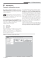
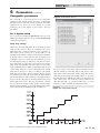
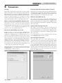
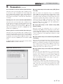
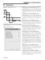
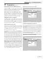
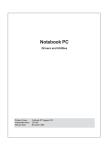
SYNC - PCP Rev A PC PROGRAM INSTRUCTIONS FOR THE SYNC Models: 1.0 -- 1.3 -- 1.5 WARNING This manual must only be used by a qualified heating installer / service technician. Read all instructions, including this manual, the SYNC Installation and Operation Manual, and the SYNC Service Manual, before installing. Perform steps in the order given. Failure to comply could result in severe personal injury, death, or substantial property damage. Save this manual for future reference. Contents 1. INSTALLATION 6. PARAMETERS Program Installation ..................................................... 3 Parameter Information Screens ...................................10 USB Installation............................................................ 3 Changeable Parameters ..............................................11 Program Setup ............................................................. 3 Set 1: System Setup ....................................................11 PC to Unit Connection.................................................. 3 Set 2: Functional Data .................................................12-13 Starting the Program .................................................... 4-6 Set 4: Menu Values......................................................13-19 2. Status Screen............................................................... 5-6 3. Graphics Screen .......................................................... 7 4. Fault History Screen .................................................... 8 5. Cascade Screen........................................................... 9 2 PC Program Instructions 1 Installation Program installation There are two programs available for programming and monitoring the SYNC boilers. SITECS937Lab is used to monitor the operation of the boiler and program a few displayrelated parameters. SMART TOUCH PC is used to program the bulk of the parameters in the controls. To begin installation of the programs, please insert your SMART SYSTEM CD into the CD drive. If you have Autostart enabled, the SMART SYSTEM software screen will load. If not, navigate to CD drive and double-click on index.html. Once the screen opens, select the program you wish to install. Follow the prompts, and after all the desired programs are installed, restart your computer. If you wish to have the PC program icons on your desktop, click on START, and then Programs. Right click on SMART TOUCH PC. Place the cursor over Send to >, and then click on Desktop. Repeat this procedure for the SITECS937Lab program. USB installation Your PC will communicate with the SMART TOUCH control through the USB cable included with your kit. This cable will require a specific USB driver. This driver may be installed by starting the SMART TOUCH PC program, clicking on the Settings pull-down menu, and clicking on the Comport > item. In the next menu, you will have the option of installing one of two USB drivers. Select the option appropriate for the operating system used by your PC. The necessary driver will install automatically. Program setup The PC will assign a ComPort to your new adapter. You will need to know the ComPort number it uses in order to tell the SMART TOUCH PC program which one to communicate with: 1. 2. Click on the following: - Start - Control Panel - System icon (use the Classic View) - Device Manager button You will see a list of the hardware on your PC. Double click on “Ports (COM&LPT)”. You will see an entry called “USB Serial Port (COM4)”. The ComPort number may be different on your computer but the device description will be the same. The SMART TOUCH PC program can communicate through Comports 1 - If the Comport assigned by your computer is avalue larger than what is available in the SMART TOUCH PC program, you will need to manually reassign the ComPort on your computer. 3. Go back to the “Ports (COM & LPT)” area referenced and take note of any unused ComPort between COM1 to COM16. Double click on the “USB Serial Port”. 4. 5. Click on the “Port Settings” tab, then on the “Advanced”button. Select an unused Comport number (preferably COM1) in the range of COM1 to COM16. Click on OK. Click OK on the previous window and then close all of the other windows. Restart your PC to make sure the new ComPort number is active. When you attach the USB cable to the PC, the PC should recognize the cable. The next time you start up the SMART TOUCH PC and SITECS937Lab programs, click on the “Settings” tab at the top of the screen, then click on“Comport”. Select the ComPort number assigned to the USB cable above. The programs display temperatures in °F. If you wish to display temperatures in °C, click on the Settings tab along the top of the Main Screen window, and move the cursor over Temperature > in the pull-down menu. A new menu will appear, click on Celsius. CAUTION DO NOT connect a phone line to any of the phone jacks on the control board. PC to Unit Connection There are three connectors in which to plug the serial communications cable on the SYNC unit (FIG. 1-a). Each one is specific to a particular function. PC Connection The PC connection is used to monitor the unit performance, data logging, programming the service provider’s name and phone number, and setting selected display parameters. Use the SITECS937Lab program for these functions. PC1 The PC1 connection is used to retrieve, view, modify, and restore parameters for controller 1. Use the SMART TOUCH PC program for these functions. PC2 The PC2 connection is used to retrieve, view, modify, and restore parameters for controller 2. Use the SMART TOUCH PC program for these functions. Figure 1-a SMART TOUCH Cable Connections PC1 CONNECTION TO VIEW AND RESTORE PARAMETERS FOR CONTROLLER 1. PC2 CONNECTION TO VIEW AND RESTORE PARAMETERS FOR CONTROLLER 2. PC CONNECTION FOR MONITORING DATA LOGGING. 3 PC Program Instructions 1 Installation Figure 1-1 SMART TOUCH PC Main Screen Figure 1-2 Sitecs937Lab Main Screen Starting the program To start one of the programs, double-click on the icon (if you put it on your desktop), or click on Start, then Programs, and select the program you wish to start. See FIG 1-1 and FIG 1-2 above. There are two access levels for this program. The user access level allows only certain settings to be changed. The installer access level allows more settings to be changed. The program defaults to the user level when started. You will notice that a lock symbol appears in the lower right-hand corner of the window. To move to the installer level, a password must be entered. This password is located on a label on the CD-ROM case. You may enter the password by clicking on the “key” button in the upper left-hand corner of the window. A window opens in which you can type in the password (see FIG. 1-3). Note that the password is case sensitive and is in all CAPS. Click on the Ok button, or press the Enter key. You will notice that the lock symbol at the lower right-hand corner of the window has changed into a key symbol. 4 There are some fields along the bottom of the window (FIG. 1-1): The left field shows the location of the program. The next field shows the status of the communication between the PC and the SMART TOUCH. This will say “No connection” when the program is started. As soon as the program sends or receives data from the SMART TOUCH, this field will show “Connected”. The right field shows the filename of the parameter file in the program’s memory (see parameters in Section 6). Figure 1-3 Password Window PC Program Instructions 2 Status Screen Figure 2-1 SMART TOUCH Status Screen To monitor and record the operation of the heater, click on the Status tab along the top of the Main Screen window (FIG. 1-1, page 4). When using the SITECS937Lab program, you will need to choose which controller you wish to monitor. The Status Screen will appear (see FIG. 2-1 above). The screen is divided into several sections. The Sensors section displays the current temperatures seen by the Inlet, Outlet, System Inlet, System Outlet, Tank, Outdoor, and Flue sensors. It also shows the delta T across the heat exchanger and the voltage being applied to the 0-10Vdc input (FIG. 2-1). The controlling sensor is shown below the items mentioned above. The default controlling sensor is the Outlet sensor. If a System Supply sensor is connected, the control will automatically use it as the controlling sensor. Below the temperature readings are Derivative Flue and Derivative Outlet. These show how quickly these temperatures are changing. The control will take certain actions based on these values. For instance, if the outlet temperature rises too quickly, the control will force the heater to run at low fire. Finally, the 0-10Vdc input Voltage and Flame Current are shown. To the right of the sensor temperature readings are the various setpoints. The SH setpoint is the setpoint the SMART TOUCH uses during a space heating call for heat. Note that this setpoint will depend upon the outdoor temperature if the outdoor air sensor is connected. When the 0-10Vdc input is used, this setpoint will vary with the input voltage if it is used to control the setpoint. The HW setpoint is the setpoint used when a Tank sensor is connected. The HW Mod Setpt is the outlet temperature setpoint used when heating an indirect HW tank. The dSP setpoint is not used. Below these is a check box indicating if Night Setback is active or not. Below the Sensors section is the Inputs section (FIG. 2-1). This section displays the status of the Enable (SH Thermostat) Input, HW Thermostat, Manual Reset High Limit, Flow Switch/Low Water Cutoff (optional), Gas Pressure Switch, Louver Proving Switch (optional), Air Pressure Switch, Blocked Drain Switch, Auto Reset High Limit Switch, and the status of the SH and DHW demands from ModBus. Next to the Inputs section is the Outputs section (FIG. 2-1). This section shows the status of the Boiler (secondary) pump, System (primary) Pump, HW Pump, Blower, Gas Valve, Run-time Contacts, and Alarm Contacts. 5 PC Program Instructions 2 Status Screen Figure 2-1 continued. . . At the top right of the window is the Fan Speed status information. Included in the Fan Speed status are Min., Max., and Ignition fan speeds. If Ramp Delay is activated, the Ramp Delay limit is shown. The target and actual fan speeds are displayed, and if the actual speed is within acceptable limits. If the SMART TOUCH is programmed to be controlled by a Building Management System (BMS), and programmed to have the BMS control the power from the boiler, then the percent of max. power is displayed. Finally, should select temperatures or the flame current approach certain limits, the SMART TOUCH will force the fan speed up or down accordingly to prevent exceeding those limits. When this happens, the box next to the corresponding sensor is checked. Below the Fan Speed status is the Boiler Configuration. This indicates the application to which the SMART TOUCH is programmed to be used and the source of control. Finally, the General status of the boiler is shown. Included in the General status is the active call for heat (if any), the active limits (if any), the last active limit, the burner status, the last fault, and the date and time as stored in the SMART TOUCH. 6 While in the SMART TOUCH Status Screen, you can generate a log file of the readings as the heater operates. Click on the Options button at the bottom right-hand corner of the screen (FIG. 2-1). Press the LogFile button and define a log file name and the directory in which you want it to be located. Click OK. When you want to start logging data, click the Log button. The Log button will turn green to indicate that it is logging. You will also notice the filename at the top of the window, and will see the size increase as data is logged to the file. To stop logging, click on the Options button, then click on the Log button again. The Log button will turn back to gray to indicate that logging has stopped. If you desire to log data over an extended period of time, you may want to select a longer Log every time so the log file doesn’t grow too large. You can also produce a bitmap of the window. Click on the Options button, then the Bitmap button. A bitmap of the window will be saved into the ENCONFLS directory below the directory in which the SMART TOUCH program resides. PC Program Instructions 3 Graphics Screen Figure 3-1 SMART TOUCH Graphics Screen The Graphics Screen allows you to observe the changes in various readings while the heater operates (see FIG. 3-1). Note that the vertical scale has two numbers for each division. By default, the Outlet Temperature, Inlet Temperature, System Supply Temperature (if connected), Outdoor Temperature (if connected), Tank Sensor Temperature (if connected), Space Heating setpoint, Tank setpoint, 0-10Vdc input voltage, and fan speed are plotted. In addition, the status of the Gas Valve Output, Flame Current, and Pump Outputs are indicated by horizontal lines. When these readings are off, the line is thin; when on, the line is wide. Any of these readings can be removed from the graph by deselecting them at the bottom of the window. The current values of these readings are also displayed at the bottom of the window as depicted in FIG. 3-1. As with the Status Screen, a log file can be generated to record the performance of the appliance. Click on the Options button to open the Options window. Click on the LogFile button to create a file name and define the folder in which to put it. Once a Log File is defined, click on the Log button to start logging the readings. The Log button will turn green to indicate that the program is logging, and the log file size will appear at the top of the Graphics Screen window. Note that the file size will increase as more readings are logged. Click on the Log button again to stop logging of the readings. The Log button will turn gray again to indicate that logging has stopped. A bitmap can also be generated of the Graphics Screen. Click on the Options button, and then the Bitmap button. A bitmap of the window will be saved into the C:/program files/SMART TOUCH PC/ENCONFLS directory. The time scale and vertical (Y) scale can be changed by clicking on the Options button to get the Options window, and then the Up or Down buttons for the desired scale. The top number represents °F, and the bottom number represents °C. Press the Ok button to close the Options window. The background color of the Graphics Screen can be changed by pressing the Display button on the Options window. 7 PC Program Instructions 4 Fault History Screen Figure 4-1 Fault History Screen The Fault History Screen provides historical data about the operation of the SMART TOUCH controls.. Click on the Fault history button along the top of the Main Screen window (FIG. 1-1), and then click on Read from Control in the pull-down menu. After uploading data from the selected program, a window will appear with the status of numerous counters and lists of the most recent events (see FIG. 4-1 above). Included are details of the control board serial number, software version, default parameters, production date, and last service date. The number of times various faults have occurred is also shown. The last 10 faults are listed, as well as the last 10 blockings (a blocking is an event that causes the burner to shut off). In addition, the number of hours the control has operated in various states is shown, as well as the number of successful and failed ignition attempts. Finally, a count of internal checks is shown. 8 The total number of occurrences of certain faults are also stored in the control and shown on the left side of the screen. The column on the right shows the total occurrences since the control was built. The column on the left shows the total occurrences since the table was reset. Press the Erase table button at the bottom of the window to clear the totals in the column on the left. This will also clear the Last 10 faults and the Last 10 blockings. Some of this information may be needed by a service technician to diagnose a problem, so provision is made to create a file in which to save this data. Click on Save file, and define a file name and the folder in which to save it. A bitmap can also be saved by clicking on the Bitmap button at the bottom of the Fault History Screen (FIG. 4-1). The bitmap file will be saved to the folder ENCONFLS located below the file in which the SMART TOUCH program resides. PC Program Instructions 5 Cascade Screen Figure 5-1 Cascade Screen The Cascade Screen provides the status of the cascade system. The PC must be connected to the Leader (address 0-1) appliance. Click on the Cascade button along the top of the Main Screen window (FIG. 1-1). The Cascade System area shows the power demand and setpoint, the boiler pump status, the boiler status, and the priority of each controller in the cascade. If a system supply sensor is connected to the Leader controller, the cascade control will send a fixed setpoint of 185°F (85°C) and a power (% modulation) command to all the heaters as required to maintain the controlled temperature at the setpoint. If a system supply sensor is not connected (NOT recommended), the Leader will send the space heating setpoint to all of the boilers in the cascade and each controller will fire as required to hold their outlet sensors to this setpoint. The Priority column indicates the order in which the controllers will fire to meet the load. This order changes every hour during the first day of operation, and every 24 hours thereafter. The Sensors area displays the system supply temperature, and space heating setpoint (see FIG. 5-1). Beneath this area is a check box indicating if Night Setback is active. Beneath that is a check box indicating if the temperature regulation is being held constant, and if the Ramp Delay feature is active. The Freeze P1 regulation box is checked when the next controller can be started up, but is held off by one of the timers. The Status area displays several important parameters. The Cascade Pump gives the status of the system pump output, and the type of heat demand (Space Heating or HW). The Cascade power shows the power target for the cascade, and the total power available. This target power may not be the same as the total power shown in the Cascade System area, due to the various time delays described below. The Cascade Max and Cascade Min values show the maximum and minimum fan speed percentages available in all of the heaters. The Off Timer and On Timer are used to force each controller to have a minimum off and on time, to prevent short cycling. The Block Switch on timer is started whenever a controller is commanded to start, and the next controller is prevented from starting until this timer times out. This allows time for the system supply sensor to read the temperature change resulting from firing the last controller, before starting the next. By clicking on the Options button, a log file can be defined, and logging can be started and stopped in the same way as with the Status and Graphics Screens previously described. A bitmap of the current screen can also be saved if desired. 9 PC Program Instructions 6 Parameters Parameter information screens By accessing the Parameter Information Screens on the SMART TOUCH program, the installer can view all of the SMART TOUCH parameters. The installer can also change certain specific parameters to fine tune the operation of the boiler to the installation. NOTE The PC cable must be connected to either the PC1 or PC2 connection. When connected, the status screen on the SYNC will show a communication error. This will clear automatically when the cable is removed. To access the parameter list, click on the Parameters button along the top of the Main Screen window (FIG. 6-1). Next click on Retrieve Parameters from Controller in the pull down menu (see FIG. 6-1). This will upload the current parameters in the SMART TOUCH to the PC. Adjustable parameters are located in: Set 1: System Setup Set 2: Functional Data Set 4: Menu Values While many parameters are viewable in each set, only select parameters are adjustable. To make an adjustment to a parameter, select the parameter to be changed from the appropriate set. Click on the box next to the parameter and type in the value for the parameter. Figure 6-1 Parameters Pull-Down Menu Screen 10 Once an adjustment has been made to a parameter, it must be programmed into the SMART TOUCH. On the Parameter pull down menu, click on the Program Parameters into Control button. This will bring up another pull down menu. If a parameter was changed in just one set, select the set from the menu and click on it. If changes were made in multiple sets, select the Store Parameter Set 0-4 from the menu and click on it. This will program the new parameters into the SMART TOUCH. If the parameters are based on a parameter set from a different model, they may not be compatible with this model. In that case, the program will display a message to let you know. You may compare parameter 1AR in the SMART TOUCH control, and in the new parameter file, to determine if they are compatible. While the programming is taking place, the SMART TOUCH will go into a lockout mode. It will require that the Reset button on the display be pressed after the programming has been completed before the unit will be allowed to operate. PC Program Instructions 6 Parameters (continued) Changeable parameters Figure 6-2 Parameter Set 1D The following is a brief discussion of the changeable parameters, their default settings, the range of adjustment, and their location. The title for the parameters may differ slightly from the PC to the boiler display. To prevent confusion, the boiler display version will be listed in parenthesis. Set 1: System setup Set 1 is accessed by clicking on Parameters at the top of the Main Screen window (FIG. 6-1), then on Set 1: Control Setup on the pull-down menu. Ramp delay settings When active, the ramp delay limits the boiler firing rate when a SH cycle has started *. There are 6 limiting steps used to limit temperature overshoot and short cycles (see FIG. 6-2). This feature can be turned on or off depending on the installation. The default condition for this feature is disabled. It should only be needed when the flow through the heat exchanger is very low, or the flow in the primary loop can be less than the flow in the secondary loop. The time for each of the 6 ramp delays as well as the power level for each of the 6 ramp delays are adjustable. The time range for each ramp delay is adjustable from 1 minute to 40 minutes with the total of all 6 ramp delays not to exceed 109 minutes. The default delay time for Periods 1, 2, and 3 is 2 minutes. The default delay time for Periods 4, 5, and 6 is 1 minute. This process can also work in reverse when the boiler shuts off. After shutting off, the max firing rate will be limited to the ramp 6 limit for the period 6 time delay, then to the ramp 5 limit for the period 5 time delay, and so forth. This step down feature overrides the step up feature until the ramp up limit becomes higher than the ramp down limit. To access the Ramp Delay settings, click on the tab labeled 1D Ramp Delay (see FIG. 6-2). *This is recommended for single-boiler installations only. The power range for each ramp delay is adjustable from 0 to 100. The defaults for each ramp delay is ramp delay 1= 20%, ramp delay 2=30%, ramp delay 3=40%, ramp delay 4=55%, ramp delay 5=75%, ramp delay 6=100% (FIG. 6-3). Note that the limit in period 6 will limit the firing rate throughout the entire call for heat. The locations for these parameters are 1DG through 1DL. See parameter 4FE (page 17 of this manual) to enable or disable the ramp delay feature. Figure 6-3 Ramp Delay Interval 11 PC Program Instructions 6 Parameters Set 2: Functional Data Set 2 is accessed by clicking on Parameters at the top of the Main Screen window, then clicking on Set 2: Functional Data on the pull-down menu (FIG. 6-1, page 10). Cascade control Parameters 2DJ and 2DK determine the time delays used by the Cascade. To access the Cascade parameters, click on the tab labeled 2D Cascade. Block time switching boiler on Parameter 2DJ is the minimum time delay between starting one burner and starting the next burner in the Cascade. The range for this parameter is 0 seconds to 255 seconds. The default value is 60 seconds. Block time switching boiler on/off Parameter 2DK is the minimum ON and OFF time for each burner in the Cascade and is used to prevent short cycling of the burners. The range for this parameter is 0 seconds to 255 seconds. The default value is 30 seconds. Block time Switch On/Off 2nd burner HW Parameter 2DR is not used on the SYNC boiler. 12 Figure 6-4 Parameter Set 2D PC Program Instructions 6 Parameters (continued) Figure 6-5 Parameter Set 2E Figure 6-6 Parameter Set 4A Parameter 2EB sets the pump delay time for the boiler pump after an over-temperature condition. This time is adjustable from 0 minutes to 40 minutes. The default time is 2 minutes. Space Heating (SH) user setpoint (User Setp) If the boiler pump or HW pump have not been active in a 24 hour period, the SMART TOUCH will activate the appropriate pump for a programmed time to prevent jamming. The boiler pump time can be changed by accessing parameter 2EC. This time is adjustable from 0 minutes to 40 minutes. The default time is 20 seconds. The HW pump time can be changed by accessing parameter 2ED. This time is adjustable from 0 minutes to 40 minutes. The default time is 20 seconds. Set 4: Menu values Set 4 contains parameters that can be accessed from the boiler display. The parameters in this set control the basic operation of the boiler. To access these parameters, click on Parameters at the top of the Main Screen window (FIG. 6-1, page 10), then click on Set 4: Menu Values on the pull-down menu (FIG. 6-6). The SH User Setpoint sets the water temperature setpoint for fixed operation or the maximum temperature setpoint when the outdoor air sensor is used. This parameter can be changed by accessing parameter 4AA. The temperature range of this parameter is 50°F to 190°F. The default value is 125°F. SH min user setpoint (Min User Setp) The SH Minimum User Setpoint sets the minimum water temperature setpoint that can be used for space heating operation. The user or installer will not be able to program the control with a lower SH setpoint. This parameter can be changed by accessing parameter 4AB. The temperature range of this parameter is 0°F to 190°F. The default value is 70°F. SH max user setpoint (Max User Setp) The SH Maximum User Setpoint sets the maximum water temperature setpoint that can be used for space heating. The user or installer will not be able to program the control with a higher SH setpoint. This parameter can be changed by accessing parameter 4AC. The temperature range of this parameter is 0°F to 190°F. The default value is 190°F. SH turn-off differential (SH off df) The SH Turn-off Differential sets how many degrees above the Max. Cascade setpoint (parameter 4AY) the outlet temperature has to go before the boiler will shut off. This parameter can be changed by accessing parameter 4AD. The temperature range of this parameter is 0°F to 86°F. The default value is 10°F. 13 PC Program Instructions 6 Parameters SH off-on differential (SH off/on df) Night setback temperature (NSB Setp) The SH Off-on Differential sets how many degrees below the turn-off temperature the outlet temperature has to go before the boiler will turn on. This parameter can be changed by accessing parameter 4AE. The temperature range of this parameter is 0°F to 86°F. The default value is 20°F. Once the internal clock has been set correctly, the night setback feature can be used to program a lower water temperature setpoint for space heating. This parameter can be changed by accessing parameter 4AK. The temperature range for this parameter is 32°F (0°C) to 140°F (60°C). With a setting of 32°F (0°C) the feature is turned off. The default value will be 32°F (0°C). Drop of inlet temp before ending anti-cycling (Drop in inlet) The control will bypass the anti-cycling time if the inlet water temperature drops too much. The control will use the inlet water temperature when it shuts off as the starting point. If the temperature drops this amount below the starting temperature, the control will abort anti-cycling and allow the boiler to fire. This parameter can be changed by accessing parameter 4AF. The temperature range of this parameter is 0°F to 86°F. The default value is 10°F. Offset HW setpoint to end HW demand When heating an indirect hot water tank (heat maker), the tank temperature (or inlet temperature if a tank sensor is not used) must rise above the tank setpoint (parameter 4AS) by this amount before the HW heat demand will end. This parameter can be changed by accessing parameter 4AG. The temperature range of this parameter is 0° to 54°F (30°C). The default setting is 0°. Outdoor air shutdown temp (Out SD Setp) When the outdoor air temperature rises above this point, the control will inhibit all SH demands (HW demands will still be active). This parameter can be changed by accessing parameter 4AH. The temperature range of this parameter is 0°F to 120°F (99°C). The default value is 80°F (27°C). OA shutdown differential (Out SD df) This is the number of degrees below parameter 4AH the outdoor air temperature must go before the boiler will again respond to an SH demand. This parameter can be changed by accessing parameter 4AI. The temperature range of this parameter is 0°F to 90°F (50°C). The default value is 10°F (5°C). Shift OA reset curve (Shift Air Reset) The Shift Heat Curve shifts the actual setpoint above or below the calculated setpoint by the number of degrees in this parameter. This parameter can be changed by accessing parameter 4AJ. The temperature range of this parameter is -27°F (-15°C) to 27°F (15°C). The default value is 0°. This feature will be active if this parameter is set to anything other than 0°. 14 SH turn-off differential cascade (Casc off df) The SH turn-off differential cascade sets how many degrees above the SH setpoint the system temperature has to go before the boiler will shut off. This parameter can be changed by accessing parameter 4AL. The temperature range of this parameter is 0°F to 72°F (40°C). The default setting is 10°F (5°C). SH off-on differential cascade (Casc off/on df) The SH off-on differential cascade sets how many degrees below the turn-off temperature the system temperature has to go before the boiler will turn back on. This parameter can be changed by accessing parameter 4AM. The temperature range of this parameter is 0°F to 72°F (40°C). The default setting is 20°F (10°C). SH anti-cycling time (Anti-C t) Once a SH demand has been satisfied, a set amount of time must elapse before the control will respond to a new SH demand. This helps prevent short cycling of the boiler. The control will inhibit the new heat demand and “Anti-cycling” will be shown on the display, until either this time has elapsed or the water temperature drops below parameter 4AF. This parameter can be changed by accessing parameter 4AO. The time range for this parameter is 0 minutes to 40 minutes. The default value is 1 minute. Max service time (Max Serv t) The service mode allows the installer to set the unit to a fixed firing rate for the purpose of combustion analysis. The delay sets the length of time the boiler will stay in the service mode if no keys have been pressed before going back to its original state. This parameter can be changed by accessing parameter 4AP. The time range of this parameter is 0 minutes to 40 minutes. The default value is 20 minutes. Tank setpoint temp This setting is applied to the tank sensor (when connected). It is used to start and stop the HW call for heat. This setting can be changed by accessing parameter 4AS. The temperature range is 60°F (15.5°C) to 190°F (87.5°C). The default setting is 120°F (49°C). PC Program Instructions 6 Parameters (continued) Tank differential temp Cascade max SH step power based (Max outl temp) This parameter determines how far below the tank setpoint the tank sensor temperature must go to start a HW call for heat. This setting can be adjusted by accessing parameter 4AT. The temperature range is 0°F (0°C) to 100°F (38°C). The default value is 5°F (3.5°C). When a system supply sensor is connected, each burner applies this setpoint to its outlet sensor during a space heating call for heat. The controls limit the modulation of each burner in order to maintain the system supply temperature at the setpoint. If an outlet temperature approaches this setting, the controls will also limit the modulation of that burner in order to not exceed the setting. The control uses parameters 4AD and 4AE to turn the burner off and back on based on this setting as well. This parameter can be changed by accessing parameter 4AY. The temperature range of this parameter is 32°F (0°C) to 212°F (100°C). The default value is 185°F (85°C). Time to switch between HW and SH (SH/HW sw tim) This feature sets the length of time the control will stay in HW mode when a SH call has been received. After this time period has expired the control will determine if a SH call needs to be serviced. If the System Supply Temperature is below the turn-on temperature, the control will revert to SH mode. Otherwise, it will remain in HW mode until the System Supply Temperature drops below the turn-on temperature. If a HW call is still active the timer will reset. After the time period has expired the control will revert to HW mode. This will continue back and forth until one of the demands has been satisfied. This parameter can be changed by accessing parameter 4AU. The time range of this parameter is 10 minutes to 240 minutes. The default value is 30 minutes. Cascade DHW setpoint offset for all members Not used. On the tabs at the top of the window (FIG. 6-7), click on the tab labeled 4C Boiler Config to set the parameters that enable BMS operation and determine the controlling sensor (see FIG. 6-7 below). Figure 6-7 Parameter Set 4C Boost function time (Boost Tim) This function will only work if the outdoor air sensor is connected. The Boost Function Time sets the amount of time that must elapse during an SH demand before the water temperature setpoint will be increased. This parameter can be changed by accessing parameter 4AV. The time range for this parameter is 1 minute to 60 minutes. The default value is 20 minutes. Boost function temp increase (Boost incr) This function will only work if the outdoor air sensor is connected. If a SH demand lasts longer than the programmed time setting in parameter 4AV, and there have been no HW demands, the control will increase the water temperature setpoint by the amount in this parameter. If the SH demand continues through another time period, the setpoint will be increased again. This will continue until either the SH demand ends, a maximum of 20 increases has occurred, or the maximum user setpoint has been reached. Once the SH demand has been satisfied the setpoint will revert back to its calculated setting. The boost temperature can be changed by accessing parameter 4AW. The temperature range of this parameter is 0°F to 45°F(25°C). The default value is 0°. This feature will be active if this parameter is set to anything other than 0°F. Outlet setpoint temp for indirect HW (Indir HW Setp) When a HW call for heat becomes active, the control will control the firing rate of the boiler in order to maintain the outlet water temperature at this setpoint. This parameter can be changed by accessing parameter 4AX. The temperature range of this parameter is 50°F (10°C) to 190°F (88°C). The default value is 180°F (82°C). Config SH control The Config SH Control parameter selects the method used to control the modulation of the boiler. This parameter must always be set to 2. BMS If BMS control of Cascade has been selected in parameter 4CG, the control must know how to use the 0-10Vdc signal. This can be either temperature based or power based. This parameter can be changed by accessing parameter 4CB. The allowable values for this parameter are “0” for power or “2” for temperature. The default value is 0. 15 PC Program Instructions 6 Parameters Cascade SH pump delay after SH demand (Boiler Pump D) Each burner control in the Cascade must be given a unique address. This address can be changed by accessing parameter 4CC. The Leader (top) burner (to which the thermostat/zone control, system sensor, and system pump (if controlled by the boiler) are connected) must be set to address 0. All the Member burners must be given an address from 1 to 15. The range of this parameter is 0 to 15. The default value is 0-1. This feature sets the length of time the boiler pump will run after a SH demand has been satisfied. This parameter is adjustable by accessing parameter 4DA. The time range for this parameter is 0 minutes to 40 minutes. The default time is 30 seconds. Master controlled through ModBus (Demand conf) If the boiler or cascade is to operate based on its own inputs, this must be set to No. The boiler can still be monitored through ModBus with this parameter set to No. If the boiler or cascade is to receive commands from ModBus, then this must be set to Yes. The default setting is No. Reload short time ModBus out of order When the boiler or cascade is receiving commands from ModBus, but using its own system supply and tank sensor readings, the commands must be refreshed at least every 4 minutes by the building automation system. This is a fixed timeout. If the boiler or cascade is receiving either the system supply temperature or the tank temperature reading from the building automation system, that information should be refreshed more often. This parameter determines how often this refresh must occur before the boiler or cascade goes into its stand-alone mode. The time range for this parameter is 0 to 120 seconds. The default value is 10 seconds. HW pump delay (HW Pump D) This feature sets the length of time that the HW pump (if connected) will run after a HW demand has been satisfied. This parameter is adjustable by accessing parameter 4DB. The time range for this parameter is 0 minutes to 40 minutes. The default time is 30 seconds. System pump delay (Sys Pump D) This feature sets the length of time the system pump (if connected) will run after a SH demand has been satisfied. This parameter is adjustable by accessing parameter 4DC. The time range for this parameter is 0 minutes to 40 minutes. The default time is 30 seconds. To set the parameters for Service Notification, click on the tab labeled 4E Notify Setup (see FIG. 6-9 below). Sys Pump (Sys Pump mode) On the tabs at the top of the window, click on the tab labeled 4D Pump Delay to set the delay time for the boiler, system, and HW pumps (see FIG. 6-8 below). The system pump can be set to operate different ways. The operating mode can be adjusted by accessing parameter 4DG. When set to 0, the system pump will run continuously. When set to 1, the system pump output will not activate. When set to 2, the system pump will turn on and off based on the space heating call for heat. The system pump will always turn off when the Outdoor Air Shutdown feature is active. The system pump will always turn on when the freeze protection feature is active. The default setting is 2. Figure 6-8 Parameter Set 4D Figure 6-9 Parameter Set 4E 16 PC Program Instructions 6 Parameters (continued) No. of months for service reminder (Serv Not time) When the boiler control determines that a scheduled service is due based on days of installation, the boiler display will show a “Maintenance Required” screen. This parameter is adjustable by accessing parameter 4EA. The time range for this parameter is 0 months to 36 months. The default time is 12 months. Running hours for service reminder (Serv Not Run h) When the boiler control determines that a scheduled service is due based on the hours of actual operation, the boiler display will show a “Maintenance Required” screen. This parameter is adjustable by accessing parameter 4EB. The time range for this parameter is 0 hours to 100,000 hours. The default time is 10,000 hours. Burner cycles for service reminder (Serv Not cycl) When the boiler control determines that a scheduled service is due based on the number of boiler cycles, the boiler display will show a “Maintenance Required” screen. This parameter is adjustable by accessing parameter 4EC. The range for this parameter is 0 cycles to 100,000 cycles. The default is 10,000 cycles. To adjust the Outdoor Air Reset curve, click on the tab labeled 4F OA Reset Curve (see FIG. 6-10 below). Figure 6-10 Parameter Set 4F OA reset water temp at min outdoor temp (4FC) (Reset T Lo Out) When the outdoor air temperature drops to its minimum setting (4FC), the water temperature setpoint will be at this value. However, if the SH user setpoint (4AA) is lower, it will override this setting. If the SH user setpoint is higher, the water temperature setpoint will continue to climb as the outdoor temperature drops below 4FC. This parameter can be changed by accessing parameter 4FA. The temperature range of this parameter is 0°F (-18°C) to 190°F. (88 °C). The default value is 180°F (82°C), (FIG 6-11, page 18). OA reset water temp at max outdoor temp (4FD) (Reset T Hi Out) When the outdoor air temperature rises to or above its maximum setting (4FD), the water temperature setpoint will be at this value. This parameter can be changed by accessing parameter 4FB. The temperature range of this parameter is 0°F (-18°C) to 190°F (88°C). The default value is 70°F (21°C), (FIG 6-11, page 18). OA reset outdoor temp at max water temp (4FA) (Out T Hi Reset) When the outdoor air temperature drops to this point, the water temperature setpoint will be at the setting given by parameter 4FA (if not overridden by the SH user setpoint). This parameter can be changed by accessing parameter 4FC. The temperature range of this parameter is -30°F (-34°C) to 90°F (32°C). The default value is 25°F (-4°C), (FIG 6-11, page 18). OA reset outdoor temp at min water temp (4FB) (Out T Lo Reset) When the outdoor air temperature rises to or above this point, the water temperature will be at its minimum setpoint. This parameter can be changed by accessing parameter 4FD. The temperature range of this parameter is -30°F (-34°C) to 90°F (32°C). The default value is 70°F (21°C), (FIG. 6-11, page 18). Ramp delay (Ramp delay) This parameter configures the ramp delay feature from off to on. This parameter can be changed by accessing parameter 4FE (FIG. 6-10). The control range of this parameter is 0 = Off, 1 = Ramp Up Only, and 2 = Ramp Up and Ramp Down. The default is 0. 17 PC Program Instructions 6 Parameters Figure 6-11 Outdoor Air Reset Curve BMS Setpoint at min voltage (BMS setpt min V) If parameter 4CB is set to 2, the control must know what minimum setpoint temperature to use. This can be changed by accessing parameter 4GA. The temperature range for this parameter is 32°F (0°C) to 248°F (120°C). The default value is 70°F (21°C). BMS Setpoint at max voltage (BMS setpt max V) If parameter 4CB is set to 2, the control must know what maximum setpoint temperature to use. This can be changed by accessing parameter 4GB. The temperature range for this parameter is 32°F (0°C) to 248°F (120°C). The default value is 180°F (82°C). BMS Voltage at low setpoint (BMS V Min Setpt) To adjust the BMS settings, click on the tab labeled 4G BMS (see FIG. 6-12 below). Figure 6-12 Parameter Set 4G If parameter 4CB is set to 2, the control must know what voltage corresponds to the minimum setpoint. This can be adjusted by accessing parameter 4GC. The voltage range for this parameter is 0Vdc to 4GD The default value is 2Vdc. BMS Voltage at high setpoint (BMS V Max Setpt) If parameter 4CB is set to 2, the control must know what voltage corresponds to the maximum setpoint. This can be adjusted by accessing parameter 4GD. The voltage range for this parameter is 0Vdc to 4GC. The default value is 10Vdc. Min BMS voltage to start demand (BMS V Heat) If parameter 4GK is set to 1, then the heat demand will be generated by the voltage present on the 0-10Vdc input. Parameter 4GE determines the voltage at which the SMART SYSTEM control initiates a heat demand. The range for this parameter is 4GF to 10Vdc. The default value is Vdc. Differential to stop BMS demand (Drop in BMS End) If parameter 4GK is set to 1, then the heat demand will be generated by the voltage present on the 0-10Vdc input. Parameter 4GF determines how far below the starting voltage (parameter 4GE) the voltage must drop before the heat demand ends. The range for this parameter is 0Vdc to 4GE. The default value is 1Vdc. BMS Power at min voltage (BMS mod @minV) If parameter 4CB is set to 0, the control must know what minimum power level is to be used. This can be changed by accessing parameter 4GG. The range for this parameter is 20% to 4GH. The default value is 20%. BMS Power at max voltage (BMS mod @maxV) If parameter 4CB is set to 0, the control must know what maximum power level is to be used. This can be changed by accessing parameter 4GH. The range for this parameter is 4GG to 100%. The default value is 100%. 18 PC Program Instructions 6 Parameters (continued) BMS Voltage at min power (BMS V @min mod) Figure 6-13 Save Parameter File Window If parameter 4CB is set to 0, the control must know what voltage corresponds to the minimum power. This can be changed by accessing parameter 4GI. The range for this parameter is 0Vdc to 4GJ The default value is 2Vdc. BMS Voltage at max power (BMS V @max mod) If parameter 4CB is set to 0, the control must know what voltage corresponds to the maximum power. This can be changed by accessing parameter 4GJ. The range for this parameter is 4GI to 10Vdc. The default value is 10Vdc. BMS Demand Enable (1) Voltage (0) If parameter 4CG is set to YES (BMS control of cascade), the heat demand can be activated either by the voltage on the 0-10Vdc input, or by closing the enable contacts. To choose the voltage input, set parameter 4GK to 0. To choose the enable input, set parameter 4GK to 1. The default value is 0. Loading stored parameters from the PC Storing parameters on your PC Once you have customized the parameters for a particular heater, you can store the new settings on your PC. This will allow you to restore these settings should you have to replace the SMART TOUCH control, or allow you to load these settings into another heater at a later date. The settings are stored as a data file. To save a file, click on Parameters at the top of the screen, then on Save data file to disk on the bottom of the pull-down menu (see FIG. 6-1 on page 10). A new window will appear (FIG. 6-13). On the top left side it shows the drive on which it will save the file. Below that is the directory it will use. These may be changed to any drive and folder you wish (for instance, a USB flash drive). At the right side is a list of the default data files. At the bottom is a field for entering the file name you wish to use. Note that the extension for this file is .pil. Make sure that you DO NOT overwrite the extension when entering the file name. You MUST NOT use any of the default file names shown in the field on the right side of the window. This could overwrite that default file! If you are updating a file, and want to overwrite the old one, you may scroll down to that file name and click on it, instead of having to type it into the field at the bottom of the window. Click on the OK button to save the file. A message will appear confirming that the file was saved. Note that the new file name appears in the lower right-hand corner of the SMART TOUCH PC program window. To retrieve a set of parameters that had been stored previously, click on Parameters at the top of the screen, then on Get data file from disk (see FIG. 6-1 on page 10). A new window will appear (FIG. 6-14). On the left top corner, select the drive on which the data file is stored, followed by the correct folder. The list of data files in that folder will be shown on the right. Click on the data file you wish to obtain. That file name will appear in the field at the bottom of the window. Click on the OK button. Note that this file name appears in the lower right-hand corner of the SMART TOUCH PC window. Figure 6-14 Get Parameter File Window 19 Revision Notes: Revision A initial release. SYNC-PCP Rev A Printed in the USA 4/10