1
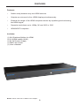
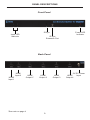
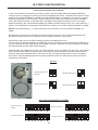
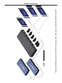
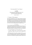
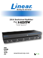
2X4 Switcher/Splitter
For
d
Model # HDMI-SW-2X4M
USER MANUAL
www.linearcorp.com
ASKING FOR ASSISTANCE
Technical Support:
Telephone
(800) 421-1587
(760) 438-7000
Fax
(760) 438-7199
Technical Support Hours:
6:30 AM - 4:30 PM PST Monday through Friday.
Email:
[email protected]
Website:
www.linearcorp.com
Notice
Linear LLC reserves the right to make changes in the hardware, packaging
and any accompanying documentation without prior written notice.
© 2008 Linear LLC, All Rights Reserved
TABLE OF CONTENTS
1. Introduction / Operation Notes
2. Features
3. Panel Descriptions
4. Connecting and Operating the 2X4 Switcher/Splitter For HDMI
5. RMT-2 Installation
6. IR Code Configuration
7. Wiring Diagram
8. Specifications
9. Warranty
INTRODUCTION
The Linear 2x4 Switcher/Splitter for HDMI is equipped with two HDMI inputs and four
HDMI outputs. Two inputs accommodate the simultaneous connection of up to two
high definition video sources, such as satellite systems and HD DVD players. Four
outputs send the high definition audio/video signals to up to four high definition displays.
Switching is done via the IR remote that is provided with the unit.
How It Works
You simply connect all your sources to the switcher’s HDMI inputs. Then connect up
to four displays to the switcher’s HDMI outputs. Once the sources, the Switcher and
the display(s) are powered and connected, you simply select which source you want
to view using the IR remote.
OPERATION Notes
READ THESE NOTES BEFORE INSTALLING OR
OPERATING THE 2X4 Switcher/SPLITTER For HDMI
•
Display information (EDID) is sent from the display connected to HDMI
output port 1 to both of the sources connected to the 2X4 Switcher/
Splitter for HDMI. If there is no display connected to HDMI output port 1,
the remaining HDMI output ports will be scanned in succession for an
EDID to use. (See note on page 4 for additional information)
•
The 2X4 Switcher/Splitter for HDMI can only mirror one input video signal at a
time to the four display outputs. The user can choose which of the two HDMI
inputs will be displayed on the four HDMI outputs
•
HDMI/HDCP compliant
•
Compatible with all HDMI and DVI* displays
NOTE: When used with a HDMI to DVI adapter.
1
FEATURES
Features
•
Switch easily between any two HDMI sources
•
Outputs are mirrored to four HDMI displays simultaneously
•
Extends the range of the HDMI compliant device by equalizing and reclocking
the HDMI signal
•
Supports resolutions up to 1080p, 2K and 1920 x 1200
•
HDMI/HDCP compliant
Includes:
(1) 2X4 Switcher/Splitter for HDMI
(2) 6 ft HDMI cables (M-M)
(1) 5V DC Power Supply
(1) RMT2-IR remote
(1) User’s Manual
NOTE: *When used with a HDMI to DVI Adapter
2
PANEL DESCRIPTIONS
Front Panel
IR Eye
Input LED
Indicator
Power LED
Indicator
IR Eye
Extension Port
Back Panel
HDMI
Input 2
HDMI
Input 1
HDMI
Output 1*
HDMI
Output 2
*See note on page 4
3
HDMI
Output 3
5V DC Power
HDMI
Input
Output 4
CONNECTING THE 2X4 SWITCHER/SPLITTER FOR HDMI
How to Connect the 2X4 Switcher/Splitter For HDMI
1.
Connect the supplied cable from the HDTV HDMI source into the HDMI input
port 1 of the 2X4 Switcher/Splitter for HDMI.
2.
Connect the second HDTV HDMI source to HDMI input port 2 on the 2X4 Switcher/
Splitter for HDMI using a user supplied HDMI cable.
3. Connect the display(s) to the HDMI output port(s)* of the 2X4 Switcher/Splitter
for HDMI using user supplied cable(s).
4. Plug the 5V DC power supply into the 2X4 Switcher/Splitter for HDMI.
NOTE: *Display information (EDID) is sent from the display connected to HDMI
output port 1 to both of the sources connected to the 2X4 Switcher/Splitter for
HDMI. If there is no display connected to HDMI output port 1, the remaining
HDMI output ports will be scanned in succession for an EDID to use. The
source will output resolutions and timings according the EDID that is being fed
by the 2X4 Switcher/Splitter for HDMI. Therefore, all of the connected displays
must be capable of accepting the timings and resolution output by the source. It
is recommended that the display with the lowest native resolution be connected to
HDMI output port 1. This is to ensure that a compatible video signal will be able to
be displayed on all connected monitors.
OPERATING THE 2X4 SWITCHER/SPLITTER FOR HDMI
Switching between the inputs on the 2X4 Switcher/Splitter for HDMI is done using
the supplied RMT2-IR remote.
IR Remote Control
Pressing button one on the remote will select the HDMI source that is connected to
HDMI input port one. Pressing two on the remote will select the HDMI source that
is connected to HDMI input port two.
4
RMT2-IR INSTALLATION
1. Remove battery cover from the back of the RMT2-IR remote.
2. Verify that dip switches 1 & 2 are in the down (OFF) position. (See page 6)
3. Insert the battery, hold the battery so that you can see the positive side facing up.
The side that is not marked must be facing down.
4. Test the RMT2-IR remote by pressing ONLY one button at a time. The indicator
light on the remote will flash once each time you press a button.
WARNING: Do not press multiple buttons simultaneously and do NOT press buttons
rapidly. These actions will cause the remote to reset and steps 1-4 will have to be
repeated.
Note: The RMT2-IR ships with two batteries. One battery is required for operation,
the second battery is complimentary.
The optional IR extender allows you to
relocate your HDMI Switcher and still retain IR
control. Linear part# IR-EXTENDER
5
IR CODE CONFIGURATION
How to Resolve IR Code Conflicts
In the event that IR commands from other remote controls conflict with the supplied RMT-2IR
remote control, changing the remote channel will alleviate this issue. The RMT-2IR remote control
and the 2X4 Switcher/Splitter for HDMI have DIP SWITCHES for configuring the remote channel
that both units use to communicate. These settings must match each other for proper operation.
The 2 DIP SWITCH bank on the RMT-2IR is located underneath the battery cover. The 8 DIP
SWITCH bank for the 2X4 Switcher/Splitter for HDMI is located inside of the unit. *DIP SWITCH 1
and 2 on the RMT-2IR correspond to DIP SWITCH 3 and 4 on the 2X4 Switcher/Splitter for HDMI.
NOTE: *DIP SWITCHES 1, 2, and 5 through 8 are not used on the 2X4 Switcher/Splitter for
HDMI.
Because the procedure for changing channels requires the main unit to be disassembled, this
procedure should only be done if there are IR conflicts present in your setup.
Disconnect power from unit before starting. Remove all cabling from unit.
To open the 2X4 Switcher/Splitter for HDMI Unit, remove all screws from the sides and underside of
the unit. Remove the hex nuts above each HDMI connector. Slide the unit apart carefully to expose
the internal PCB and the 8 DIP SWITCH bank.
Carefully slide the PCB back into the unit. Being careful not to over tighten the hex nuts, screw them
back in above each HDMI connector and on the RS-232 serial connector. Screw all of the screws
from the sides and underside of the unit back into the unit, again being careful not to over tighten
the screws. Plug all cabling back into its proper location on the unit. Reconnect power to the unit
and test for IR conflicts.
Remote
Remote Channel 1:
Default
Remote Channel 2:
1
2
Remote Channel 3:
1
2
1
2
Remote Channel 4:
1
2
2X4 Switcher/Splitter For HDMI
Remote Channel 1:
Default
Remote Channel 2:
1 2 3 4 5 6 7 8
1 2 3 4 5 6 7 8
Remote Channel 3:
Remote Channel 4:
1 2 3 4 5 6 7 8
1 2 3 4 5 6 7 8
6
Maximum HDMI cable length is 15 ft at 1080P resolution without the use of an HDMI-SB or HDMI-CAT5-EXT
WIRING DIAGRAM
8
SPECIFICATIONS
VideoAmplifier Bandwidth: .............................................................. 165 MHz
Input Video Signal: ...................................................................... 1.2 Volts p-p
Input DDC Signal: .................................................................. 5 Volts p-p (TTL)
Single Link Range: ........................................................... 1080p/1920 x 1200
HDMI Connector: ............................................................ TypeA19 pin female
Power Supply: .................................................................................... 5V DC
Power Consumption: ............................................................. 10 Watts (max)
Dimensions: ............................................................... 12”W x 1.25”H x 4.25”D
Shipping Weight: .................................................................................. 4 lbs.
9
WARRANTY
Note: These products are designed to be installed and serviced by trained professional
installation companies.
Linear LLC warrants this product to be free from defects in material and workmanship. For the
term of the warranty, see the list of products below. The Warranty Expiration Date is reflected by
a date code that is affixed to all of Linear’s products. This warranty extends only to wholesale
customers who buy direct from Linear or through Linear’s normal distribution channels. Linear
does not warrant this product to consumers. Consumers should inquire from their selling dealer
as to the nature of the dealer’s warranty. There are no obligations or liabilities on the part of
Linear LLC for consequential damages arising out of or in connection with use or performance
of this product or other indirect damages with respect to loss of property, revenue, or profit, or
cost of removal, installation or reinstallation. All implied warranties, including implied warranties
for merchantability and implied warranties for fitness, are valid only until warranty expiration date
as labeled on the product. This Linear LLC Warranty is in lieu of all other warranties express or
implied. Some states and countries do not allow limitations or how long an implied warranty lasts
or the exclusion or limitation or incidental or consequential damages, so the above exclusions
may not apply. The Linear LLC warranty gives specific legal rights in addition to other rights,
which may exist and vary from state to state and country to country.
All products returned for warranty service require a Return Product Authorization Number (RPA#).
Contact Linear Technical Services at 1-800-421-1587 for an RPA# and other important details.
Consumers: If you have trouble locating your installing company, please contact Linear LLC at
1-800-421-1587 and we will assist you with locating a service and Installation Company.
The following warranty period applies to this set of Linear branded products.
1.
Linear High Definition Video products — Two (2) years. There is no warranty offered on the
batteries supplied with the IR remote Control.
The warranty is limited to repair or replacement of products returned, freight prepaid, to
Linear LLC. There is NO PROVISION FOR LABOR COST OR OTHER REIMBURSEMENTS
OF ANY KIND.
1.
Failures due to product abuse, negligence, improper installation, improper use, and
electrical surge including damage from lightning, water damage or other damage due to
natural disasters are not covered by the warranty.
2.
The warranty shall also be voided by any tampering with the date code, labels or other
markings on the product.
3.
Products that are damaged in transit to Linear LLC due to improper packaging or by the
carrier (shipping company) will not be covered under the warranty. If the product was
damaged or lost by the carrier, it is the sender’s responsibility to create a claim against the
carrier.
4.
The user is responsible for all labor costs associated with removing, reinstalling and
returning the product to Linear LLC.
5.
Linear LLC, at its option, will repair or replace the defective product.
6.
Replacements will be made from B-Stock. If an exact replacement is not available Linear
LLC, at its option will select the nearest equivalent product. The user is responsible for
freight charges to Linear LLC.
7.
Linear LLC will return warranted repaired or replacements by UPS Ground or an equivalent
service. A customer may pay the additional costs for second day or next-day service.
10
H D MI -S W-2X 4M
(7 6 0 ) 4 3 8 -7 0 0 0
(80 0 ) 4 2 1 -1 5 8 7 FA X (8 0 0 ) 4 6 8-1340
www. lin e a rc o rp . c o m
R ev A