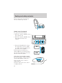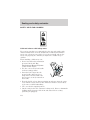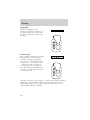
1
Contents
Before driving
Introduction
2
Instrumentation
3
Controls and features
20
Seating and safety restraints
87
Starting and driving
Starting
110
Driving
115
Roadside emergencies
130
Servicing
Maintenance and care
147
Capacities and specifications
191
Customer assistance
197
Reporting safety defects
209
Index
210
All rights reserved. Reproduction by any means, electronic or mechanical
including photocopying, recording or by any information storage and retrieval
system or translation in whole or part is not permitted without written
authorization from Ford Motor Company.
Copyright r 1998 Ford Motor Company
1
Introduction
ICONS
Indicates a safety alert. Read the
following section on Warnings.
Indicates vehicle information related
to recycling and other
environmental concerns will follow.
Correct vehicle usage and the
authorized disposal of waste
cleaning and lubrication materials are significant steps towards
protecting the environment.
Indicates a message regarding child
safety restraints. Refer to Seating
and safety restraints for more
information.
Indicates that this Owner Guide
contains information on this subject.
Please refer to the Index to locate
the appropriate section which will
provide you more information.
2
Introduction
WARNINGS
Warnings provide information which may reduce the risk of personal
injury and prevent possible damage to others, your vehicle and its
equipment.
BREAKING-IN YOUR VEHICLE
There are no particular breaking-in rules for your vehicle. During the
first 1 600 km (1 000 miles) of driving, vary speeds frequently. This is
necessary to give the moving parts a chance to break in.
INFORMATION ABOUT THIS GUIDE
The information found in this guide was in effect at the time of printing.
Ford may change the contents without notice and without incurring
obligation.
3
Instrumentation
Instrument
cluster
(pg. 6)
Headlamp
control
(pg. 24)
Turn signal and
wiper/washer
control
(pg. 48)
4
–
TURN ON
HEAD
LAMPS
T/C
OFF
NO
RM
P
5
60
6
ABS
7
40
C
80 100
3
60
20
2
E
km/h
40
FILL ON RIGHT
SERVICE
ENGINE
SOON
0
AIR
BAG
200
0
RPMx1000
0
MPH
HI
LO
LIGHTS
AUTO
LAMP
P
RESUME
SET ACCEL
COAST
ON
Instrument panel
Auto lamp (pg. 25) dimmer switch
(pg. 25)
* If equipped
4
100
180
OFF
OFF
140
160
20
BRAKE
0FF
80
120
1
H
!
+
F
SRS
Speed control
(pg. 50)
Driver air bag
(pg. 101)
120
Instrumentation
Electronic sound
system control*
(pg. 49)
Message Center
(pg. 12)
Clock
(pg. 32)
Electronic sound
system
(pg. 32)
SYSTEM
DRIVER ID
SELECT
L
C
E
A
O
VEHICLE HANDLING
DISPLAY
I
MENU
T
N
TRIP
N
T
RESET
DTE ECON
N
000000.0
BAL
BASS
SEL
VOL
PUSH ON
TREB
CD
NEXT
SEEK
MUTE
VOL
MODE
TEMP
EJ
TAPE
AM
FM
RDS
SCAN
TUNE
1
2
3
REW
FF
SIDE 1 2
FADE
4
AUTO
5
6
COMP
SHUFF
FAN
FRONT
REAR
EXT
OFF
AUTO
HI
MAX
A/C
BACK
BACK
BOTH
BOTH
HEATED
Climate controls*
(pg. 49)
Heated seat
control*
(pg. 94)
HI
0
0
OFF
OFF
SEATS
Climate control
systems
(pg. 26)
5
Instrumentation
WARNING LIGHTS AND CHIMES
4
–
NO
RM
P
60
6
ABS
7
40
60
20
2
E
C
80 100
km/h
80
120
40
140
160
20
100
180
1
H
!
5
3
F
TURN ON
HEAD
LAMPS
T/C
OFF
+
FILL ON RIGHT
SERVICE
ENGINE
SOON
0
AIR
BAG
200
0
RPMx1000
0
MPH
120
000000.0
BRAKE
Service engine soon
Your vehicle is equipped with a
SERVICE
computer that monitors the engine’s
ENGINE
emission control system. This
SOON
system is commonly known as the
On Board Diagnostics System
(OBD II). This OBD II system
protects the environment by ensuring that your vehicle continues to
meet government emission standards. The OBD II system also assists the
service technician in properly servicing your vehicle.
The Service Engine Soon indicator light illuminates when the ignition is
first turned to the ON position to check the bulb. If it comes on after the
engine is started, one of the engine’s emission control systems may be
malfunctioning. The light may illuminate without a driveability concern
being noted. The vehicle will usually be drivable and will not require
towing.
What you should do if the Service Engine Soon light illuminates
Light turns on solid:
This means that the OBD II system has detected a malfunction.
Temporary malfunctions may cause your Service Engine Soon light to
illuminate. Examples are:
1. The vehicle has run out of fuel. (The engine may misfire or run
poorly.)
2. Poor fuel quality or water in the fuel.
3. The fuel cap may not have been properly installed and securely
tightened.
6
Instrumentation
These temporary malfunctions can be corrected by filling the fuel tank
with good quality fuel and/or properly installing and securely tightening
the gas cap. After three driving cycles without these or any other
temporary malfunctions present, the Service Engine Soon light should
turn off. (A driving cycle consists of a cold engine startup followed by
mixed city/highway driving.) No additional vehicle service is required.
If the Service Engine Soon light remains on, have your vehicle serviced
at the first available opportunity.
Light is blinking:
Engine misfire is occurring which could damage your catalytic converter.
You should drive in a moderate fashion (avoid heavy acceleration and
deceleration) and have your vehicle serviced at the first available
opportunity.
Under engine misfire conditions, excessive exhaust temperatures
could damage the catalytic converter, the fuel system, interior
floor coverings or other vehicle components, possibly causing a fire.
Air bag readiness
Momentarily illuminates when the
ignition is turned ON. If the light
fails to illuminate, continues to flash
or remains on, have the system
serviced immediately.
AIR
BAG
Safety belt
Momentarily illuminates when the
ignition is turned to the ON position
to remind you to fasten your safety
belts. For more information, refer to
the Seating and safety restraints
chapter.
Brake system warning
Momentarily illuminates when the
ignition is turned to the ON position
and the engine is off. If the brake
warning lamp does not illuminate at
this time, seek service immediately.
!
P
BRAKE
7
Instrumentation
Also illuminates when the parking brake is engaged. Illumination after
releasing the parking brake indicates low brake fluid level and the brake
system should be inspected immediately.
Anti-lock brake system (ABS)
Momentarily illuminates when the
ignition is turned to the ON position
ABS
and the engine is off. If the light
remains on, continues to flash or
fails to illuminate, have the system
serviced immediately. With the ABS light on, the anti-lock brake system
is disabled and normal braking is still effective unless the brake warning
light also remains illuminated with parking brake released.
Turn signal
Illuminates when the left or right
turn signal or the hazard lights are
turned on. If one or both of the
indicators stay on continuously or
flash faster, check for a burned-out
turn signal bulb. Refer to Exterior bulbs in the Maintenance and care
chapter.
High beams
Illuminates when the high beam
headlamps are turned on.
Turn on headlamps (if equipped)
Illuminates to remind the driver to
turn the headlamps on when:
• the daytime running lamps are on
• the autolamps are off
• the autolamp sensor determines it
is nighttime
8
TURN ON
HEAD
LAMPS
Instrumentation
Charging system
Illuminates when the ignition is
turned to the ON position and the
engine is off. The light also
illuminates when the battery is not
charging properly, requiring
electrical system service.
Engine oil pressure
Momentarily illuminates when the
ignition is turned to the ON position
and the engine is off. Illuminates
when the oil pressure falls below the
normal range. Stop the vehicle as
soon as safely possible and switch off the engine immediately. Check the
oil level and add oil if needed. Refer to Engine oil in the Maintenance
and Care chapter.
Traction ControlY off light
Illuminates when the Traction
Controly system has been disabled
(by the driver or as a result of a
system failure). For more
information, refer to the Driving
chapter.
T/C
OFF
Safety belt warning chime
Chimes to remind you to fasten your safety belts.
For information on the safety belt warning chime, refer to the Seating
and safety restraints chapter.
Supplemental restraint system (SRS) warning chime
For information on the SRS warning chime, refer to the Seating and
safety restraints chapter.
Key-in-ignition warning chime
Sounds when the key is left in the ignition in the OFF/LOCK or ACC
position and the driver’s door is opened.
9
Instrumentation
Headlamps on warning chime
Sounds when the headlamps or parking lamps are on, the ignition is off
(and the key is not in the ignition) and the driver’s door is opened.
Turn signal chime
Sounds when the turn signal lever has been activated to signal a turn
and the vehicle is driven more than 0.8 km (1/2 mile).
GAUGES
–
NO
RM
P
60
6
ABS
7
40
60
20
2
E
C
80 100
km/h
80
120
40
140
160
20
100
180
1
H
!
5
3
F
TURN ON
HEAD
LAMPS
T/C
OFF
4
+
FILL ON RIGHT
SERVICE
ENGINE
SOON
0
AIR
BAG
200
0
RPMx1000
0
MPH
120
000000.0
BRAKE
Fuel gauge
Displays approximately how much
F
fuel is in the fuel tank (when the
key is in the ON position). The fuel
gauge may vary slightly when the
vehicle is in motion. The ignition
should be in the OFF position while
E
the vehicle is being refueled. When
the gauge first indicates empty,
FILL ON RIGHT
there is a small amount of reserve
fuel in the tank. When refueling the
vehicle from empty indication, the amount of fuel that can be added will
be less than the advertised capacity due to the reserve fuel.
A minimum of six gallons must be added or removed from the fuel tank
in order for the gauge to instantaneously update. If less than six gallons
is the change, the gauge will take between five to ten minutes to update.
10
Instrumentation
Speedometer
Indicates the current vehicle speed.
60
40
20
80
80 100
km/h
60
120
140
40
100
160
20
180
200
0
0
MPH
120
Odometer
The odometer is located in the message center. It registers the total
kilometers (miles) of the vehicle. Pressing the E/M control will alternate
between English (miles) and Metric (kilometers) measurements.
Tachometer
Indicates the engine speed in
revolutions per minute.
Driving with your tachometer
pointer in the red zone may damage
the engine.
4
5
6
ABS
7
3
2
1
0
RPMx1000
H
NO
RM
Engine coolant temperature gauge
Indicates the temperature of the
engine coolant. At normal operating
temperature, the needle remains
within the normal area (the area
between the “H” and “C”). If it
enters the red section, the engine is
overheating. Stop the vehicle as
C
soon as safely possible, switch off
the engine immediately and let the
engine cool. Refer to Engine
coolant in the Maintenance and care chapter.
AIR
BAG
11
Instrumentation
Never remove the coolant reservoir cap while the engine is
running or hot.
This gauge indicates the temperature of the engine coolant, not the
coolant level. If the coolant is not at its proper level the gauge indication
will not be accurate.
ELECTRONIC MESSAGE CENTER
The electronic message center only
SYSTEM
works when the ignition is in the
ON position.
E/M
The message center tells you about
the condition of your vehicle by two
methods:
MENU
SELECT
• operator selectable features
VEHICLE HANDLING
• continuous warning reporting of
monitored systems
TRIP
DISPLAY
You can select different features for
the message center to display by
DTE ECON
RESET
using the message center controls
located to the right of the
instrument cluster. You will hear a tone when you press one of these
controls. However, the message center will display the appropriate
warning message if it detects a warning from any of the monitored
systems.
12
Instrumentation
If you have a vehicle with the Driver
Select System, you have a DRIVER
ID control in place of the E/M
control.
• Refer to DRIVER ID
(if equipped) for DRIVER ID
control information.
• Refer to E/M (if equipped) for
E/M control information.
SYSTEM
DRIVER ID
MENU
SELECT
VEHICLE HANDLING
TRIP
DISPLAY
RESET
DTE ECON
Operator selectable features
These features are controlled by the message center controls located to
the right of the instrument cluster.
System check
Pressing this control causes the
SYSTEM
message center to cycle through a
status of each of the systems being
monitored. For each of the monitored systems, the message center will
indicate either an OK message or a warning message for three seconds.
The sequence of the system check report is as follows:
• voltage level
• engine temperature
• oil level
• engine coolant level
• washer fluid level
• doors closed (driver and passenger side). This message can only be
reset by closing the door(s). If the RESET control is pressed, PLEASE
CLOSE DOOR will be displayed.
• trunk closed
• exterior lamps (front turn, brake and tail)
• fuel level
13
Instrumentation
• distance to empty
• traction control
• ride control
System warnings
System warnings alert you to possible problems or malfunctions in your
vehicle’s operating systems.
The message center will display the
RESET
last selected feature if there are no
more warning messages. This allows
you to use the full functionality of
the message center after you acknowledge the warning by pressing the
RESET control and clearing the warning message.
Door Ajar
Driver’s Door Ajar
Check Engine Temp
Transmission Overheat
Check Transmission
Low Oil Level
Check Charging System
Low Fuel Level
Low Engine Coolant
Low Tire Pressure (if equipped)
Gear Display Data ERR
Brake Lamp Out
Check Traction Control
Check Ride Control
Trunk Ajar
Check Steering Assist
Low Washer Fluid
Air Leveling Disabled
Tail Lamp Out
Check FRT Turn Lamps
Turn on Headlamps
14
Cannot be reset
Warning returns after 10 minutes
Warning reappears after key is
turned from OFF to ON
Instrumentation
Warning messages that have been reset are divided into two categories:
• They will reappear on the display ten minutes from the reset.
• They will not reappear until an ignition OFF-ON cycle has been
completed. This acts as a reminder that these warning conditions still
exist within the vehicle.
TRIP
Press this control to display the first
of two trip odometers. Press it again
to display the second trip odometer.
To reset the displayed trip
odometer, press the RESET control.
TRIP
RESET
DTE/ECON
• Press the DTE/ECON control
DTE ECON
once to display the approximately
how far you can drive before
running out of fuel, or the
distance to empty (DTE). To ensure accuracy, turn the ignition OFF
when you fill the tank.
• Press the DTE/ECON control a second time to display the average fuel
economy in liters/100 kilometers or miles/gallon, based on distance
traveled and rate of fuel used information.
• To reset this feature, press the
RESET
RESET control while average fuel
economy is displayed (while you
are driving).
DTE is calculated using a running average fuel economy initialized by the
factory. This value is not the same as the average fuel economy display.
The running average fuel economy is based on more than 800 kilometers
(500 miles) of driving history, and is reinitialized if the battery is
disconnected.
If the FUEL LEVEL ERROR message is displayed, there is a problem
with the fuel indication system and you should contact your dealer for
service as soon as possible.
15
Instrumentation
E/M (if equipped)
Press this control to switch the
odometer and the message center
display from metric (kilometers) to
English (miles) units, and to change
the temperature indication on the climate control unit.
DRIVER ID (if equipped)
Press this control to set vehicle
comfort settings for up to two
drivers. Seat and mirror position and
vehicle handling characteristics can
be set with this control.
E/M
DRIVER ID
RESET
Press this control to reset:
RESET
• warnings
• average fuel economy
• trip odometers
The other selectable features are unaffected by pressing RESET.
DISPLAY
Press this control to turn the
message center display off. Press it
again to turn the display on.
Warnings override an off display and
must be reset for the display to be off again.
DISPLAY
VEHICLE HANDLING
Press this control once to adjust
VEHICLE HANDLING
RIDE CONTROL SETTINGS
(if equipped) between NORMAL,
PLUSH and FIRM. This feature
cannot be adjusted on vehicles not
equipped with the Memory Profile with Driver Select System.
Press this control a second time to adjust the STEERING EFFORT
SETTINGS between NORMAL, LOW and HIGH.
16
Instrumentation
Press the SELECT control to change
SELECT
these settings while in VEHICLE
HANDLING mode. The combination
of firm ride control (if equipped)
and low steering effort is undesirable and cannot be selected.
MENU
Press this control to change various
convenience settings throughout the
vehicle. Each press of the MENU
control will display a different
convenience setting.
MENU
Save to driver (if equipped)
Display appears if the driver is unidentified.
This allows you to select driver setting one, two or off.
Traction control
• Settings: ON or OFF.
• Original setting: ON.
• Setting adjustment is made using the message center MENU/SELECT
controls. (Defults to ON at each start-up.)
Refer to Traction Controly for more information.
MEMORY PROFILE
The Memory Profile allows for two primary drivers to save their
individual seat and outside rearview mirror position preferences. The
feature will then be set to the remote entry transmitter, that will
automatically recall the saved individualized preferences when that
individual identifies themselves to the system before entering the vehicle.
The Message Center info allows the driver to program the vehicle
features (listed in Memory profile system) according to their driving
preferences. These feature preferences will be saved as the vehicle
settings. To change a feature setting see Memory profile features in this
section.
Memory Profile System with Driver Select System (if equipped)
Memory Profile System with Driver Select System allows the two primary
drivers to select and save individualized settings for the features listed
17
Instrumentation
under Operator Selectable Features. Refer to “Message Center” in this
chapter for more information on the Message Center controls. The
Message Center has a Driver ID control, which when pressed, allows the
driver to select either Driver 1, Driver 2 or OFF. Selecting OFF will turn
the system OFF.
Operator selectable features
The Memory Profile System and the Memory Profile Systen with Driver
Select System access to the following the vehicle features:
• Express window
• Auto door locks
• Horn chirp
• Easy entry/exit seat access
• Reverse mirrors
• Adjustable ride (Driver Select System only)
• Adjustable steering
• Autolamp on/delay time
• Instrument panel dim control
• Driver’s seat position
• Outside mirror position
Basic operation of Memory Profile System
In order for the system to be able to store or recall an individual’s seat or
mirror position preferences, the Memory Profile must first recognize who
will be driving the vehicle. Drivers may identify themselves to the system
one of two ways:
• Pressing the unlock control on the appropriate remote transmitter key
(DRIVER MEMORY 1 or DRIVER MEMORY 2 is identified by the
number on the back of the remote transmitter) before opening the
driver’s door.
• Entering either the DRIVER MEMORY 1 or DRIVER MEMORY 2
personalized code into the keyless entry keypad before opening the
driver’s door. For information on programming personalized codes see
Keyless entry system in the Control and features section.
Pressing OFF will turn the system off.
18
Instrumentation
Once the system has identified the driver (DRIVER MEMORY 1 or
DRIVER MEMORY 2), the seat and mirror will automatically begin to
move to that driver profile. Changes made to the seat or mirror positions
will automatically be saved to that profile.
If the driver should enter the vehicle without first identifying themselves,
all features will remain at their last setting or position and any settings
will be saved as vehicle settings not individualized settings.
If Driver 1 or Driver 2 wishes to
make temporary changes to their
seat or outside mirror positions
ON
OFF
without affecting their preferred
positions they may do so by:
• Using the switch on the back of
the remote transmitter to turn
the Memory Profile System OFF
prior to pressing the unlock
control on the remote transmitter.
• Entering the vehicle without
identifying themselves using the
two methods listed above.
This option may be useful to temporarily reposition the driver’s seat and
mirrors during an extended drive.
Associated systems
Keyless Entry System
For information on programming personalized codes see Keyless entry
system in the Control and features section.
The Message Center System
The Message Center is used to display Memory Profile messages and
warning and program many of the Memory Profile System features. Press
the following controls for desired programming:
• The MENU control will display options for the Express Window, Auto
Door Locks, Horn Chirp, Easy Entry/Exit Seat Access and Reverse
Mirror features which can be set by using the SELECT control.
• The VEHICLE HANDLING control will display options for Adjustable
Steering and Adjustable Ride (Driver Select System only) features
which can be set using the SELECT control.
19
Instrumentation
• The DRIVER ID control will display the option of selecting Driver 1,
Driver 2 or OFF (Driver Select System only).
Memory profile features
Express window
• Setting is saved as vehicle setting only.
• Vehicle with optional Driver Select System, setting may be saved to
either the DRIVER MEMORY 1 or 2 personalized profiles or as a
vehicle setting.
• Settings-ON or OFF
• Original setting-ON
• Setting adjustment made using: Message Center-MENU/SELECT
controls
Auto door locks
• Setting is saved as vehicle setting only.
• Vehicle with optional Driver Select System, setting may be saved to
either the DRIVER MEMORY 1 or 2 personalized profiles or as a
vehicle setting.
• Settings-ON or OFF
• Original setting-ON
• Setting adjustment made using: Message Center-MENU/SELECT
controls
Horn chirp
• Setting is saved as vehicle setting only.
• Vehicle with optional Driver Select System, setting may be saved to
either the DRIVER MEMORY 1 or 2 personalized profiles or as a
vehicle setting.
• Settings-ON or OFF
• Original setting-ON
• Setting adjustment made using: Message Center-MENU/SELECT
controls
Easy entry/exit seat access
• Setting is saved as vehicle setting only.
20
Instrumentation
• Vehicle with optional Driver Select System, setting may be saved to
either the DRIVER MEMORY 1 or 2 personalized profiles or as a
vehicle setting.
• Settings-ON or OFF
• Original setting-ON
• Setting adjustment made using: Message Center-MENU/SELECT
controls
Reverse mirrors
• Setting is saved as vehicle setting only.
• Vehicle with optional Driver Select System, setting may be saved to
either the DRIVER MEMORY 1 or 2 personalized profiles or as a
vehicle setting.
• Settings-ON or OFF
• Original setting-ON
• Setting adjustment made using: Message Center-MENU/SELECT
controls
English/Metric
• Setting is saved as vehicle setting only.
• Settings-ENGLISH or METRIC
• Original setting-ON
• Setting adjustment made using: Message Center-MENU/SELECT
controls or Message Center Switch-ENGLISH/METRIC on vehicles not
equipped with the optional Driver Select System.
Adjustable ride
• Not available on vehicles without Driver Select System option.
• Vehicle with optional Driver Select System, setting may be saved to
either the DRIVER MEMORY 1 or 2 personalized profiles or as a
vehicle setting.
• Settings-plush, normal, firm
• Original setting-normal
• Setting adjustment made using: Message Center-VEHICLE
HANDLING/SELECT controls
21
Instrumentation
Adjustable steering
• Setting is saved as vehicle setting only.
• Vehicle with optional Driver Select System, setting may be saved to
either the DRIVER MEMORY 1 or 2 personalized profiles or as a
vehicle setting.
• Settings-low, normal, high
• Original setting-normal
• Setting adjustment made using: Message Center-VEHICLE
HANDLING/SELECT controls
Autolamp on/delay time
• Setting is saved as vehicle setting only.
• Vehicle with optional Driver Select System, setting may be saved to
either the DRIVER MEMORY 1 or 2 personalized profiles or as a
vehicle setting.
For information on autolamp on/delay see Autolamp control in the
Control and features section.
Instrument panel dim control setting
• Setting is saved as vehicle setting only.
• Vehicle with optional Driver Select System, setting may be saved to
either the DRIVER MEMORY 1 or 2 personalized profiles or as a
vehicle setting.
• Settings-variable
• Original setting-maximum
• Setting adjustment made using: Lighting Control Module-panel dim
control.
For information on instrument panel dim control see Panel dimmer
control in the Control and features section.
Driver’s seat position
• Setting may be saved to either the DRIVER MEMORY 1 or 2
personalized profiles or as a vehicle setting.
• Vehicle with optional Driver Select System, setting may be saved to
either the DRIVER MEMORY 1 or 2 personalized profiles or as a
vehicle setting.
22
Instrumentation
• Settings-8–way adjustment
• Original setting-N/A
• Setting adjustment made using: driver seat control
Outside mirror position
• Setting may be saved to either the DRIVER MEMORY 1 or 2
personalized profiles or as a vehicle setting.
• Vehicle with optional Driver Select System, setting may be saved to
either the DRIVER MEMORY 1 or 2 personalized profiles or as a
vehicle setting.
• Settings-horizontal and vertical
• Original setting-N/A
• Setting adjustment made using: outside mirror control
23
Controls and features
HEADLAMP CONTROL
Rotate the headlamp control to the
first position to turn on the parking
lamps only. Rotate to the second
position to also turn on the
headlamps.
0FF
P
The exterior lamps will illuminate when the ignition is ON and the
windshield wiper control is in the interval, LO or HI position.
The instrument panel lighting will dim noticeably approximately 15
seconds after the wipers are turned on. The lights will remain in this
state until 30 seconds after the wipers are turned off.
Daytime running lamps (DRL) (if equipped)
Turns the headlamps on with a reduced output. To activate:
• the engine must be running and
• the headlamp control is in the OFF or Parking lamps position.
Always remember to turn on your headlamps at dusk or during
inclement weather. The Daytime Running Light (DRL) System
does not activate your tail lamps and generally may not provide
adequate lighting during these conditions. Failure to activate your
headlamps under these conditions may result in a collision.
High beams
Push forward to activate.
HI
LO
S
OFF
24
F
Controls and features
Flash to pass
Pull toward you to activate and
release to deactivate.
HI
LO
F
S
OFF
PANEL DIMMER CONTROL
Use to adjust the brightness of the
instrument panel during headlight
and parklamp operation.
• Push up to brighten.
• Push down to dim.
PANEL
DIM
AUTOLAMP CONTROL
The autolamp system provides light
AUTO
sensitive automatic on-off control of
LAMP
the exterior lights normally
controlled by the headlamp control.
The autolamp system also keeps the
MAX
lights on for a preselected period of
OFF
time after the ignition switch is
turned to OFF.
• To turn autolamps on, push the
control up toward the MAX position. As you press this switch, the
autolamp system’s status will be displayed in the message center. The
system can be set to provide light for up to three minutes after you
turn the ignition OFF.
• To turn autolamps off, push the control down toward OFF.
25
Controls and features
CLIMATE CONTROL SYSTEM
Electronic Automatic Temperature Control (EATC) system
The EATC system will maintain a
˚F
selected temperature and
automatically control airflow. You
AUTO
can override automatic operation
with any of the override controls,
the fan speed control or the steering
wheel controls (if equipped).
EXT
Turning the EATC on
Press AUTO, any of the override
controls or the fan speed control.
The EATC will only operate when
the ignition is in the ON position.
OFF
AUTO
AUTO
FRONT
REAR
AUTO
OFF
REAR
MAX
A/C
˚F
EXT
FRONT
MAX
A/C
Turning the EATC off
Press OFF. The Outside
Temperature (EXT) function will
continue to operate until the
ignition is turned off.
EXT
OFF
AUTO
MAX
A/C
Automatic operation
Press AUTO and select the desired temperature. The selected
temperature and the word AUTO will appear in the display window. The
EATC system will either heat or cool to achieve the selected
temperature. The system will automatically determine fan speed, airflow
location and if fresh outside air or recirculated air is required. Fan speed
remains automatic unless the fan speed control is pressed or the steering
wheel controls (if equipped) are pressed.
When in AUTO and weather conditions require heat, air will be sent to
the floor. However, if the engine is not warm enough to provide heat, the
fan will not operate. In 31⁄2 minutes or less, the fan speed will start to
increase and the airflow location will change to the floor area.
26
Controls and features
If unusual conditions exist (i.e.-window fogging, etc.), the manual
override controls allow you to select airflow locations and the fan control
allows you to adjust fan speed as necessary.
Temperature selection
The display window indicates the
selected temperature, function
(AUTO or one of the override
controls) and manual control of fan
) if automatic fan speed
speed (
is not desired.
To control the temperature, select
any temperature between 18°C
(65°F) and 29°C (85°F) by pressing
the temperature control.
˚F
AUTO
FRONT
REAR
For continuous maximum cooling, push the temperature control until
16°C (60°F) is shown in the display window. The EATC will continue
maximum cooling (disregarding the displayed temperature) until a
warmer temperature is selected by pressing the temperature control.
For continuous maximum heating, push the temperature control until
32°C (90°F) is shown in the display window. The EATC will continue
maximum heating (disregarding the displayed temperature) until a
cooler temperature is selected by pressing the temperature control.
Temperature conversion
Press MAX A/C and FRONT
at
the same time (for one second) to
switch between Fahrenheit and
Celsius.
FRONT
˚C
EXT
EXT
OFF
AUTO
REAR
MAX
A/C
Your vehicle has an English/Metric (E/M) control to change your
electronic message center display from English to Metric. This control
will also change the temperature display. Refer to Electronic Message
Center in the Instrumentation chapter.
27
Controls and features
Fan speed (
)
When AUTO is pressed, fan speed is
adjusted automatically for existing
conditions. You can override fan
speed at any time. To control fan
speed manually, press the fan
control or the steering wheel fan
speed control to cancel automatic
MAX
EXT
OFF
AUTO
A/C
fan speed operation. Press the
control up for higher fan speed or
down for lower fan speed. Press the
steering wheel control up for higher fan speed or down for lower fan
speed.
The display will show
and a bar
˚F
graph to indicate manual fan
operation and relative speed.
AUTO
To return to automatic fan operation, press AUTO.
Manual override controls
The override controls allow you to
determine where airflow is directed.
To return to full automatic control,
press AUTO.
˚F
AUTO
EXT
OFF
AUTO
FRONT
REAR
MAX
A/C
and
The air conditioning compressor will operate in all modes except
. It will also operate only when required when AUTO has been
selected. However, the air conditioning will only function if the outside
temperature is about 10°C (50°F) or above.
Since the air conditioner removes considerable moisture from the air
during operation, it is normal if clear water drips on the ground under
the air conditioner drain while the system is working and even after you
have stopped the vehicle.
Under normal conditions, your vehicle’s climate control system should be
left in any position other than MAX A/C or OFF when the vehicle is
parked. This allows the vehicle to “breathe” through the outside air inlet
duct.
28
Controls and features
• MAX A/C-Uses recirculated air to cool the vehicle. The temperature
will display 16°C (60°F). To exit, press AUTOMATIC or any other
override controls. MAX A/C is noisier than normal A/C but more
economical and will cool the inside of the vehicle faster. Airflow is
from the instrument panel registers. This mode can also be used to
prevent undesirable odors from entering the vehicle.
•
-Distributes outside air through the instrument panel registers.
However, the air cannot be cooled below the outside temperature
because the air conditioning does not operate in this mode.
-Distributes outside air through the instrument panel registers
•
and the floor ducts. Heating and air conditioning capabilities are
provided in this mode. The air will be heated or cooled based on the
temperature selection. For added customer comfort, the air
distributed through the floor ducts will be slightly warmer than the air
sent to the instrument panel registers.
•
-Allows for maximum heating by distributing outside air through
the floor ducts. However, the air cannot be cooled below the outside
temperature because the air conditioning does not operate in this
mode.
-Distributes outside air through the windshield defroster ducts
•
and the floor ducts. Heating and air conditioning capabilities are
provided in this mode. The air will be heated or cooled based on the
temperature selection. For added customer comfort, the air
distributed through the floor ducts will be slightly warmer than the air
sent to the windshield defroster ducts. If the temperature is about
10°C (50°F) or higher, the air conditioner will automatically
dehumidify the air to prevent fogging.
-Distributes outside air through the windshield defroster
• FRONT
ducts. It can be used to clear ice or fog from the windshield. If the
outside air temperature is about 10°C (50°F) or higher, the air
conditioner will automatically dehumidify the air to prevent fogging.
• OFF-Outside air is shut out and the fan will not operate. For short
periods of time only, use this mode to prevent undesirable odors from
entering the vehicle.
29
Controls and features
Displaying outside temperature
Press EXT to display the outside air
temperature. It will be displayed
until EXT is pressed again.
EXT
OFF
AUTO
MAX
A/C
If the selected temperature is changed while the outside temperature is
displayed, the new temperature will be displayed for four seconds after it
is changed, then the outside temperature will return to the window.
If a manual override function is selected while the outside temperature is
displayed, the new function will be displayed for four seconds after it is
changed, then the outside temperature will return to the window along
with the override selection.
The outside temperature reading is most accurate when the vehicle is
moving. Higher readings may be obtained when the vehicle is not
moving. The readings that you get may not agree with temperatures
given on the radio due to differences in vehicle and station locations.
Operating tips
• In humid weather, select FRONT
before driving. This will prevent
your windshield from fogging. After a few minutes, select any desired
position.
• To prevent humidity buildup inside the vehicle, don’t drive with the
climate control system in the OFF position.
• Don’t put objects under the front seat that will interfere with the
airflow to the back seats.
• Remove any snow, ice or leaves
from the air intake area (at the
bottom of the windshield).
30
Controls and features
• If your vehicle has been parked with the windows closed during hot
weather, the air conditioner will do a much faster job of cooling if you
drive for two or three minutes with the windows open. This will force
most of the hot, stale air out of the vehicle. Then operate the air
conditioner as you would normally.
• If the air conditioner works well in MAX A/C but not in normal A/C,
this may indicate that the cabin air filter (if equipped) needs to be
replaced.
• When placing objects on top of your instrument panel, be careful to
not place them over the defroster outlets. These objects can block
airflow and reduce your ability to see through your windshield. Also,
avoid placing small objects on top of your instrument panel. These
objects can fall down into the defroster outlets and block airflow and
possibly damage your climate control system.
REAR WINDOW DEFROSTER
The rear defroster control is located
on the instrument panel.
FRONT
Press the rear defroster control to
REAR
clear the rear window of thin ice
and fog.
• The small LED will illuminate
when the rear defroster is
activated.
The ignition must be in the ON position to operate the rear window
defroster.
The defroster turns off automatically after 10 minutes or when the
ignition is turned to the OFF position. To manually turn off the defroster
before ten minutes have passed, push the control again.
31
Controls and features
CLOCK
Press + to increase the time
displayed.
C
L
A
O
T
N
N
T
I
N
E
Press – to decrease the time
displayed.
C
L
A
O
T
N
N
T
I
N
E
USING YOUR AUDIO SYSTEM
Your audio system is equipped with selective lighting, a unique lighting
strategy. This lighting feature is operable when the headlamps are
illuminated. During the operation of any selected mode, lighting for the
individual function controls will either illuminate or turn off. Those
controls which have a function for the specific mode of operation
selected will be lit, while the controls which have no function for that
mode will be turned off.
32
Controls and features
High Level Audio System with Premium AM/FM Stereo/Cassette
(Radio Controlled CD Changer Compatible)
BAL
BASS
SEL
VOL
PUSH ON
CD
TREB
FM
RDS
SCAN
TUNE
SEEK
MUTE
AM
EJ
DOLBY B NR
TAPE
1
2
REW
FF
4
3
FADE
SIDE 1-2
AUTO
5
6
COMP
SHUFF
Premium AM/FM Stereo/Cassette/Alpine Audio System (Radio
Controlled CD Changer Compatible)
BASS
BAL
SEL
TREB
VOL
PUSH ON
CD
TAPE
SEEK
MUTE
AM
FM
EJ
TUNE
1
2
3
REW
FF
SIDE 1-2
4
FADE
RDS
DSP
SCAN
AUTO
5
6
COMP
SHUFF
33
Controls and features
Your vehicle is equipped with a delayed accessory feature. This feature
enables the audio playing media to continue playing up to 10 minutes
after the ignition has been turned off, or until a door is opened.
Volume/power control
Press the control to turn the audio
system on or off.
VOL
PUSH ON
Turn the control to raise or lower
volume.
VOL
PUSH ON
If the volume is set above a certain level and the ignition is turned off,
the volume will come back on at a “nominal” listening level when the
ignition switch is turned back on.
Speed sensitive volume
With this feature, radio volume changes automatically and slightly with
vehicle speed to compensate for road and wind noise.
The recommended level for speed sensitive volume is from level 1
through level 3. Level 0 turns the speed sensitive volume off and level 7
is the maximum setting.
With the radio on, press and hold
the volume control for five seconds,
then press:
VOL
PUSH ON
34
Controls and features
•
to increase volume
compensation
•
to decrease or shut off the
volume compensation
AM/FM select
The AM/FM select control works in
radio, tape and CD modes (if
equipped).
SEL
AM
FM
AM/FM select in radio mode
This control allows you to select AM or FM frequency bands. Press the
control to switch between AM, FM1 or FM2 memory preset stations.
AM/FM select in tape mode
Press this control to stop tape play and begin radio play.
AM/FM select in CD mode (if equipped)
Press this control to stop CD play and begin radio play.
Tune adjust
The tune control works in radio or CD mode (if equipped).
Tune adjust in radio mode
• Press
to move to the next
TUNE
frequency down the band
(whether or not a listenable
station is located there). Hold the
control to move through the frequencies quickly.
to move to the next frequency up the band (whether or not
• Press
a listenable station is located there). Hold for quick movement.
35
Controls and features
Tune adjust for CD changer (if equipped)
• Press
to select the previous
TUNE
disc in the CD changer. (Play will
begin on the first track of the
disc unless the CD changer is in
shuffle mode.) Refer to Shuffle feature for more information. Hold the
control to continue reversing through the disc.
• Press
to select the next disc in the CD changer. Hold the control
to fast-forward through the remaining discs.
Seek function
The seek function control works in radio, tape or CD mode
(if equipped).
Seek function in radio mode
• Press
to find the next
listenable station down the
frequency band.
to find the next
• Press
listenable station up the frequency band.
SEEK
Seek function in tape mode
• Press
to listen to the previous selection on the tape or return to
the beginning of the current selection.
• Press
to listen to the next selection on the tape.
Seek function for CD changer (if equipped)
• Press
to seek to the previous
track of the current disc. If a
SEEK
selection has been playing for
three seconds or more and you
press
, the CD changer will replay that selection from the
beginning.
• Press
to seek forward to the next track of the current disc. After
the last track has been completed, the first track of the current disc
will automatically replay.
36
Controls and features
Scan function
The scan function works in radio,
tape or CD mode (if equipped).
SCAN
Scan function in radio mode
Press the SCAN control to hear a brief sampling of all listenable stations
on the frequency band. Press the SCAN control again to stop the scan
mode.
Scan function in tape mode
Press the SCAN control to hear a short sampling of all selections on the
tape. (The tape scans in a forward direction. At the end of the tape’s
first side, direction automatically reverses to the opposite side of the
tape.) To stop on a particular selection, press the control again.
Scan function in CD mode (if equipped)
Press the SCAN control to hear a short sampling of all selections on the
CD. (The CD scans in a forward direction, wrapping back to the first
track at the end of the CD.) To stop on a particular selection, press the
control again.
Radio station memory preset
The radio is equipped with four or six station memory preset controls.
These controls can be used to select up to four or six preset AM stations
and eight or twelve FM stations (four to six in FM1 and four to six in
FM2).
Setting memory preset stations
1. Select the frequency band with the AM/FM select control.
2. Select a station. Refer to Tune adjust or Seek function for more
information on selecting a station.
3. Press and hold a memory preset control until the sound returns,
indicating the station is held in memory on the control you selected.
1
2
REW
FF
3
SIDE 1-2
4
5
6
COMP
SHUFF
37
Controls and features
Autoset memory preset
Autoset allows you to set strong radio stations without losing your
original manually set preset stations. This feature is helpful on trips
when you travel between cities with different radio stations.
Starting autoset memory preset
1. Select a frequency using the AM/FM select controls.
2. Press the control.
3. When the first six strong stations
AUTO
are filled, the station stored in
memory preset control 1 will start
playing.
If there are less than six strong stations available on the frequency band,
the remaining memory preset controls will all store the last strong
station available.
To deactivate autoset and return to your audio system’s manually set
memory stations, press the control again.
Bass adjust
The bass adjust control allows you
to increase or decrease the audio
system’s bass output.
BASS
SEL
TREB
SEL
Treble adjust
The treble adjust control allows you
to increase or decrease the audio
system’s treble output.
38
Controls and features
Speaker balance adjust
Speaker sound distribution can be
adjusted between the right and left
speakers.
BAL
SEL
FADE
SEL
Speaker fade adjust
Speaker sound can be adjusted
between the front and rear
speakers.
Tape/CD select (if equipped)
• To begin tape play (with a tape
TAPE
loaded into the audio system)
while in the radio or CD mode,
press the TAPE control. Press the
button during rewind or fast forward to stop the rewind or fast
forward function.
• To begin CD play (if CD[s] are
loaded), press the CD control.
CD
The first track of the disc will
begin playing. After that, CD play
will begin where it stopped last.
Rewind
The rewind control works in tape
1
2
and CD modes (if equipped).
REW
FF
• In tape mode, radio play will
continue until rewind is stopped
(with the TAPE control) or the beginning of the tape is reached.
39
Controls and features
• In CD mode, pressing the REW control for less than three seconds
results in slow rewind. Pressing the control for more than three
seconds results in fast rewind.
Fast forward
The fast forward control works in
tape and CD modes (if equipped).
1
2
REW
FF
• In the tape mode, tape direction
will automatically reverse when
the end of the tape is reached.
• In CD mode, pressing the control for less than three seconds results in
slow forward action. Pressing the control for more than three seconds
results in fast forward action.
Tape direction select
Press SIDE 1–2 to play the alternate
side of a tape.
3
4
SIDE 1-2
Eject function
Press the control to stop and eject a
tape.
EJ
DolbyT noise reduction
Dolbyt noise reduction operates
3
4
only in tape mode. Dolbyt reduces
SIDE 1-2
the amount of hiss and static during
tape playback.
control to activate (and deactivate) Dolbyt noise reduction.
Press the
The noise reduction system is manufactured under license from Dolby
Laboratories Licensing Corporation.
Compression feature
Compression adjust brings soft and
loud CD passages together for a
more consistent listening level.
40
5
6
COMP
SHUFF
Controls and features
Press the COMP control to activate and deactivate compression adjust.
Shuffle feature
The shuffle feature operates in CD
5
6
mode and plays all tracks on the
COMP
SHUFF
current disc in random order. If
equipped with the CD changer, the
shuffle feature continues to the next disc after all tracks are played.
Press the SHUFFLE control to start this feature. Random order play will
continue until the SHUFFLE control is pressed again.
Radio data system (RDS) feature
This feature allows your audio
system to receive text information
RDS
from RDS-equipped FM radio
stations.
Press and hold the RDS control for
five seconds to turn the feature on or off. Press the control to scroll
through the following selections:
Traffic
• Press the RDS control until
TRAFFIC is displayed.
• Use the SEL control to select ON
or OFF. With the feature on, use
the SEEK or SCAN control to
find a radio station broadcasting a
traffic report (if it is broadcasting
RDS data).
Program type
• Press the RDS control until FIND
program type is displayed.
RDS
SEL
RDS
41
Controls and features
• Use the SEL control to select the
program type. With the feature
on, use the SEEK or SCAN
control to find the desired
program type from the following
selections:
• Classic
• Country
• Info
• Jazz
• Oldies
• R&B
• Religious
• Rock
• Soft
• Top 40
Show
• RDS sends information with the
FM broadcast: station name,
station type, and/or radio text.
• With RDS activated, press the
RDS control until SHOW is
displayed.
• Use the SEL control to select
TYPE, NAME or NONE.
SEL
RDS
SEL
RDS clock feature
Refer to Setting the clock for information.
42
Controls and features
Mute mode
Press the control to mute the
playing media. Press the control
again to return to the playing media.
MUTE
Digital signal processing (if equipped)
The digital signal processing (DSP)
feature allows you to change the
DSP
signal mode to suit your listening
tastes.
Press the control to turn the feature
on or off.
Use the SEL control to select the
desired signal mode (the selected
mode will appear in the display).
SEL
The following signal modes can be
selected:
• JAZZ CLUB—jazz club with
clearly reflected sounds.
• HALL—rectangular concert hall capacity of about 2 000.
• CHURCH—church with a high vault.
• STADIUM—outdoor stadium with a capacity of about 30 000.
• NEWS—“voice-only” type of sound with a limited audio band.
Press the DSP control until one of
the following appears:
DSP
• ALL SEATS
• DRIVER SEAT
• REAR SEATS
Use the SELECT control to change
the equalization to the desired
mode.
SEL
43
Controls and features
CD changer (if equipped)
Your CD changer is either located in the passenger’s footwell area or in
the center console.
Slide the door to access the CD
changer magazine.
Press
to eject the magazine.
Make sure only one disc is inserted
in each slot. Each disc must be
inserted with the label surface
upward. You may insert up to six
CDs.
COMPACT
DIGITAL AUDIO
44
6
5
4
3 6 COMPACT DISC MAGAZINE
2
1
Controls and features
The magazine does not need to be
full for the changer to operate.
Radio power must be turned on to play the CDs in the changer. The
magazine may be stored in the glove compartment when not being used.
The CD magazine may be inserted or ejected with the radio power off.
Troubleshooting the CD changer (if equipped)
The laser beam used in the compact disc player is harmful to the
eyes. Do not attempt to disassemble the case.
If sound skips:
• You may be traveling on a rough road, playing badly scratched discs or
the disc may be dirty. Skipping will not scratch the discs or damage
the player.
If your changer does not work, it may be that:
• A disc is already loaded where you want to insert a disc.
• The disc is inserted with the label surface downward.
• The disc is dusty or defective.
• The player’s internal temperature is above 60°C (140°F). Allow the
player to cool down before operating.
• A disc with format and dimensions not within industry standards is
inserted.
Cleaning compact discs
Inspect all discs for contamination before playing. If necessary, clean
discs only with an approved CD cleaner and wipe from the center out to
the edge. Do not use circular motion.
45
Controls and features
CD and CD changer care
• Handle discs by their edges only. Never touch the playing surface.
• Do not expose discs to direct sunlight or heat sources for extended
periods of time.
• Do not insert more than one disc into each slot of the CD changer
magazine.
Cleaning cassette player
Clean the tape player head with a cassette cleaning cartridge after ten to
twelve hours of play in order to maintain the best sound and operation.
Cassette and cassette player care
• Use only cassettes that are 90 minutes long or less.
• Do not expose tapes to direct sunlight, high humidity, extreme heat or
extreme cold. Allow tapes that may have been exposed to extreme
temperatures to reach a moderate temperature before playing.
• Tighten very loose tapes by inserting a finger or pencil into the hole
and turning the hub.
• Remove loose labels before inserting tapes.
• Do not leave tapes in the cassette player for a long time when not
being played.
Radio frequency information
The Federal Communications Commission (FCC) and the Canadian Radio
and Telecommunications Communications (CRTC) establish the
frequencies AM and FM stations may use for their broadcasts. Allowable
frequencies are:
AM 530, 540–1600, 1610 kHz
FM 87.9, 88.1–107.1, 107.9 MHz
Not all frequencies are used in a given area.
46
Controls and features
Radio reception factors
Three factors can affect radio reception:
• Distance/strength. The further an FM signal travels, the weaker it is.
The listenable range of the average FM station is approximately 40 km
(24 miles). This range can be affected by “signal modulation.” Signal
modulation is a process radio stations use to increase their
strength/volume relative to other stations.
• Terrain. Hills, mountains and tall buildings between your vehicle’s
antenna and the radio station signal can cause FM reception problems.
Static can be caused on AM stations by power lines, electric fences,
traffic lights and thunderstorms. Moving away from an interfering
structure (out of its “shadow”) returns your reception to normal.
• Station overload. Weak signals are sometimes captured by stronger
signals when you pass a broadcast tower. A stronger signal may
temporarily overtake a weaker signal and play while the weak station
frequency is displayed.
The audio system automatically switches to single channel reception if it
will improve the reception of a station normally received in stereo.
Audio system warranties and service
Refer to the “Warranty Guide” for audio system warranty information.
If service is necessary, see your dealer or a qualified technician.
POSITIONS OF THE IGNITION
1. ACCESSORY, allows the electrical
4
accessories such as the radio to
3
operate while the engine is not
5
running.
2. LOCK, locks the steering wheel,
2
automatic transmission gearshift
lever and allows key removal.
1
3. OFF, shuts off the engine and all
accessories without locking the
steering wheel.
4. ON, all electrical circuits operational. Warning lights illuminated. Key
position when driving.
5. START, cranks the engine. Release the key as soon as the engine
starts.
47
Controls and features
WINDSHIELD WIPER/WASHER CONTROLS
Rotate the windshield wiper control
to the desired interval, low or high
speed position.
The bars of varying length are for
intermittent wipers. When in this
position rotate the control upward
for fast intervals and downward for
slow intervals.
Push the control on the end of the
stalk to activate washer. Push and
hold for a longer wash cycle. The
washer will automatically shut off
after ten seconds of continuous use.
HI
LO
F
S
OFF
HI
LO
F
S
OFF
Windshield wiper/washer features
The exterior lamps will illuminate when the ignition is ON and the
windshield wiper control is in the interval, LO or HI position.
The instrument panel lighting will dim noticeably approximately 15
seconds after the wipers are turned on. The lights will remain in this
state until 30 seconds after the wipers are turned off.
TURN SIGNAL CONTROL
• Push down to activate the left
turn signal.
• Push up to activate the right turn
signal.
HI
LO
F
S
OFF
Cornering lamps (if equipped)
When the turn signal is used when the headlamps are on, the cornering
lamps will light either the right or left side depending on the direction of
the turn.
48
Controls and features
The flash rate of the turn signal will speed up considerably if the
Lighting Control Module detects a left or right turn lamp bulb (front or
rear) is burned out.
STEERING WHEEL CONTROLS (IF EQUIPPED)
Radio control features
• Press BAND/MODE to select AM,
FM1, FM2, TAPE or CD (if
equipped).
In Radio mode:
• Press MEM/NEXT to select a
preset station from memory.
NEXT
MODE
In Tape mode:
• Press MEM/NEXT to listen to the next selection on the tape.
In CD mode:
• Press MEM/NEXT to listen to the next track on the disc.
In any mode:
• Press VOL up or down to adjust the volume.
Climate control features
• Press TEMP up or down to adjust temperature.
• Press FAN up or down to adjust fan speed.
49
Controls and features
SPEED CONTROL
To turn speed control on
• Press ON.
Vehicle speed cannot be controlled
until the vehicle is traveling at or
ON
above 48 km/h (30 mph).
When the ON control is pressed, the
OFF
message “SPEED CONTROL
READY” will appear for 5 seconds in
your message center. Or, if the
speed control is already ON and
SET, the message “SPEED CONTROL SET” will appear for 5 seconds in
your message center.
Do not use the speed control in heavy traffic or on roads that
are winding, slippery, or unpaved.
Do not shift the gearshift lever into N (Neutral) with the speed
control on.
To turn speed control off
• Press OFF or
• Turn off the vehicle ignition.
ON
OFF
Once speed control is switched off, the previously programmed set speed
will be erased.
When the OFF control is pressed, the message “SPEED CONTROL OFF”
will appear for 5 seconds in your message center.
50
Controls and features
To set a speed
• Press SET ACC/SET ACCEL. For
speed control to operate, the
speed control must be ON and
the vehicle speed must be greater
than 48 km/h (30 mph).
RES
SET
ACCEL
COAST
When the SET ACCEL control is pressed, the message “SPEED
CONTROL SET” will appear for 5 seconds in your message center.
If you drive up or down a steep hill, your vehicle speed may vary
momentarily slower or faster than the set speed. This is normal.
Speed control cannot reduce the vehicle speed if it increases above the
set speed on a downhill. If your vehicle speed is faster than the set
speed while driving on a downhill, you may want to shift to the next
lower gear or apply the brakes to reduce your vehicle speed.
If your vehicle slows down more than 16 km/h (10 mph) below your set
speed on an uphill, your speed control will disengage. “SPEED
CONTROL CANCELED” will appear for 5 seconds in your message
center. This is normal. Pressing RES/RSM/RESUME will re-engage it.
Do not use the speed control in heavy traffic or on roads that
are winding, slippery, or unpaved.
To set a higher set speed
• Press and hold SET ACC/SET
ACCEL. Release the control when
the desired vehicle speed is
reached or
• Press and release SET ACC/SET
ACCEL. Each press will increase
the set speed by 1.6 km/h
(1 mph) if (E) English is selected
or 2 km/h (1.25 mph) if (M)
Metric is selected in the Message Center.
RES
SET
ACCEL
COAST
51
Controls and features
• Accelerate with your accelerator pedal, then press and release SET
ACC/SET ACCEL.
When the SET ACCEL control is pressed and released, the message
“SPEED CONTROL SET” will appear for 5 seconds in your message
center.
You can accelerate with the accelerator pedal at any time during speed
control usage. Releasing the accelerator pedal will return your vehicle to
the previously programmed set speed.
To set a lower set speed
• Press and hold CST/COAST.
Release the control when the
desired speed is reached or
• Press and release CST/COAST.
Each press will decrease the set
speed by 1.6 km/h (1 mph) if (E)
English is selected or 2km/h
(1.25 mph) if (M) Metric is
selected in the Message Center.
• Depress the brake pedal. When
the desired vehicle speed is
reached, press SET ACC/SET
ACCEL.
When the COAST or SET ACCEL
control is pressed and released, the
message “SPEED CONTROL SET”
will appear for 5 seconds in your
message center.
RES
SET
ACCEL
COAST
RES
SET
ACCEL
COAST
To disengage speed control
• Depress the brake pedal.
When the brake pedal is depressed, the message “SPEED CONTROL
CANCELED” will appear for 5 seconds in your message center.
Disengaging the speed control will not erase the previously programmed
set speed.
52
Controls and features
• Press the OFF control.
Pressing OFF will erase the
previously programmed set speed.
When the OFF control is pressed,
the message “ SPEED CONTROL
OFF” will appear for 5 seconds in
your message center.
To return to a previously set speed
• Press RES/RSM/RESUME. For
RES/RSM/RESUME to operate,
the vehicle speed must be faster
than 48 km/h (30 mph).
When the RESUME control is
pressed, the message “SPEED
CONTROL SET” will appear for 5
seconds in your message center.
ON
OFF
RES
SET
ACCEL
COAST
TILT STEERING
Pull the tilt steering control toward
you to move the steering wheel up
or down. Hold the control while
adjusting the wheel to the desired
position, then release the control.
53
Controls and features
Never adjust the steering wheel when the vehicle is moving.
INTERIOR LAMPS
Map lamps
To turn on the map lamps, press the
control next to each lamp.
If equipped with a moon roof, the
map lamps are located on the
rearview mirror. Press the control
next to the map lamp to illuminate
the lamp.
Rear courtesy/reading lamps
The courtesy lamp lights when:
• any door is opened.
• the instrument panel dimmer
switch is held up until the
courtesy lamps come on.
• any of the remote entry controls
are pressed and the ignition is
OFF.
With the ignition key in the ACC or ON position, the reading lamp can be
turned on by pressing the rocker control.
54
Controls and features
LINCOLN RESCU SYSTEM (IF EQUIPPED)
Lincoln RESCU runs a self-test
when you start your vehicle. During
this test, the Lincoln RESCU
warning light (located in the
overhead console) will illuminate for
several seconds. If a problem is
detected during the self-check, the
light will remain lit and the message
“RESCU FAILURE” will be displayed
on the vehicle’s message center for
several seconds.
S.O.S.
i
INFO
S.O.S. i
INFO
If the warning light fails to
illuminate when you start your
vehicle, or if it remains lit, have
your Lincoln RESCU System
INFO
checked by an authorized dealer as
soon as possible. Your system may be inoperative.
i S.O.S.
It is important that you understand the limitations of your
Lincoln RESCU System prior to initiating an activation. See
Lincoln RESCU System Limitations later in this chapter for details.
The RESCU system can be activated in three ways:
1. By pressing the Information
control.
i
INFO
2. By pressing the Emergency
(S.O.S) control.
S.O.S.
3. The system will automatically activate if the vehicle’s air bags have
been deployed.
55
Controls and features
Quick summary
• To utilize your vehicle’s RESCU system, your cellular phone must be
activated and plugged into the vehicle interface.
• Information or emergency assistance can be requested whenever your
key is in the RUN/START position and for six minutes after the vehicle
is turned off.
• An assistance request is initiated by pressing either the Information or
Emergency control located in the overhead console.
• When a control is pressed, a warning lamp located in the overhead
console will begin to flash and status messages will display on the
vehicle’s message center (messages can only be displayed when the
key is in the RUN/START position).
• The vehicle’s cellular phone automatically places a call to a 24 hour
emergency response center.
• When contact is made, the vehicle sends an electronic data message
to the response center’s computer. This data message includes latitude
and longitude coordinates obtained from the vehicle’s positioning
system and customer identification information.
• Once the data transmission is complete, the call is forwarded to a
response center operator who confirms your location using a
computerized map.
• The vehicle’s cellular handset is locked-out, the phone is automatically
placed in the “hands-free” mode and voice communication is
established with the operator through the “hands-free” microphone.
• Typically, voice communication with an operator is established within
one minute after an assistance control is pressed.
• The operator verbally obtains details of your situation and, if
necessary, ties your vehicle into a three-way phone call with the
United States Auto Club or local 911 or other emergency services to
dispatch the appropriate assistance to your location.
• Once the situation has been appropriately handled, the operator will
terminate the call, the system warning light will stop flashing and the
system will be reset. In most situations, only the response center can
terminate an assistance request.
56
Controls and features
General description
Lincoln’s Remote Emergency Satellite Cellular Unit (RESCU) is designed
to expedite roadside, emergency or information assistance to distressed
motorists who are uncertain of their location and/or are uncertain of who
to contact for assistance.
The Lincoln RESCU system utilizes Global Positioning System (GPS)
technology and the nation’s cellular phone network to track vehicle
location and, at the touch of a control, put you in voice contact with the
Lincoln Security Response Center.
Two controls in the overhead console will activate the system:
An Information icon is provided for
customer information, such as
points of interest near your current
location, route assistance and other
INFO
services as they become available.
i
An Emergency icon is provided for
emergency assistance.
S.O.S.
When you select a control, the vehicle’s cellular phone will automatically
place a call to the response center’s central computer. Once contact is
made, an electronic data message will be transmitted. This data message
will include:
• Type of alarm (Information, emergency or air bag acitvation)
• Customer Identification Number (CID)
• Latitude and longitude coordinates
• Last recorded speed and direction of the vehicle
• Time tag identifying when last position was taken
• Call-back phone number
After the transmission is complete, the call is forwarded to an operator
who will verify the details of the request and confirm the vehicle’s
location using a computerized map.
57
Controls and features
Information icon
The Information icon is provided for
customer information, such as
points of interest near your current
location, route assistance and other
INFO
services as they become available.
There may be charges incurred for certain services.
i
Emergency (S.O.S) icon (emergency assistance)
The Emergency (S.O.S) control
should be selected if emergency
assistance is required. This feature
should be used:
• if you have been involved in an
accident.
• to report a crime or fire.
• when medical attention is required.
• to receive assistance in an emergency situation.
When this control is pressed, the Lincoln Security Response Center
relays details of your situation and your location to the appropriate
authorities via three-way phone call. While the appropriate authorities
dispatch help to your location, the response center will:
• dispatch the emergency help to your location.
• when appropriate, stay in direct phone contact with you until
emergency help arrives.
• notify pre-designated family contacts or friends of the emergency
situation, if requested, or if no response is received from the vehicle.
If you are certain of your location, a direct phone call to 911 or other
emergency services may provide a faster response.
If roadside assistance is required, the Lincoln Security Response Center
will contact the Lincoln Commitment Roadside Assistance provider via
three–way phone call.
S.O.S.
58
Controls and features
Activation and deactivation
When either of the two Lincoln RESCU controls are pressed, or the air
bags are deployed (this will activate the system as an emergency
automatically), a warning light, located in the overhead console, will
begin to flash and status messages will be displayed on the vehicle’s
message center, confirming an assistance request has been made. The
warning light will continue to flash throughout the activation.
The system can be activated whenever your ignition key is in the
RUN/START position and for six minutes after your vehicle is turned off.
Once a RESCU control has been pressed, do not attempt to crank the
engine as this may cancel the activation. In most situations, the
assistance request can only be terminated and the system reset when a
special tone is sent to the vehicle by the Lincoln Security Response
Center. (See Automatic redial later in this chapter for exceptions.)
Operation will continue even if the vehicle is turned off during an
activation (although visual feedback via the message center will not be
available in this situation).
INFO activations can be cancelled by pressing the END button on the
cellular phone.
Cellular phone interface
The cellular phone must be connected to the vehicle and activated for
the system to work. During an activation, Lincoln RESCU takes control
of the vehicle’s cellular phone. If the phone is in use, the call will be
terminated and the Lincoln Security Response Center will automatically
be dialed. The cellular handset becomes inoperative and all voice
communication with the operator is accomplished via the cellular phone’s
“hands-free” microphone.
When an activation is terminated, your phone is left unlocked, in the ON
state and may not return to its previous call restriction or system
selection setting. It can be reprogrammed to your previous setting as
desired.
Refer to your cellular phone user’s manual for further information.
59
Controls and features
Message center interface
During an activation, Lincoln RESCU communicates with the vehicle’s
message center. Status messages describing the sequence of the steps
being executed are displayed, allowing you to visually follow the
activation process. The following messages are typical of those displayed
during an assistance request. They are as shown in the order in which
they would appear:
• INFO REQUEST or S.O.S REQUEST
• CALL IN PROGRESS
• RINGING RESPONSE CENTER
• SENDING LOCATION DATA
• DATA RECEIVED
• WAITING FOR OPERATOR
Once an assistance request is made, it will typically take less than one
minute until contact is made with an operator. During voice
communication the following messages will alternately toggle on the
display:
• CID XXXXXXXXXX
• LAT XXXXXXXXXX
• LON XXXXXXXXXX
• HDG XX
These messages respectively are the customer identification number,
vehicle latitude, vehicle longitude and heading. Under special conditions,
the operator may ask you to read the information being displayed on the
message center.
Automatic redial
As described previously, when an assistance request is made, the
vehicle’s cellular phone automatically dials the Lincoln Security Response
Center’s central computer and attempts to send an electronic data
message. On rare occasions, it can be difficult for the computer to
recognize the message if the cellular connection is weak or noisy. If the
transmission of the message is unsuccessful, the data call will be
terminated and the message “REDIAL IN PROGRESS” will be displayed
on the message center. A second call will automatically be placed which
bypasses the response center’s computer and is forwarded directly to an
operator.
60
Controls and features
Similarly, if the cellular call is disconnected by the network prior to
receipt of the termination tone, another call to the response center will
also automatically be dialed. The message “REDIAL IN PROGRESS” will
be displayed on the message center and voice communication with an
operator will be restored.
During redial calls, full control of the cellular phone is returned to you.
Pressing either PWR or END on the cellular handset will terminate the
assistance request and reset the system.
Location data retransmit capability
During an activation, the Lincoln Security Response Center operator has
the capability to initiate a retransmission of the electronic data message.
This may be necessary to ensure a more precise determination of vehicle
location or to track a vehicle that is moving. To accomplish the
retransmit, a special tone is sent to the vehicle by the response center.
In this situation you will temporarily lose voice contact with the operator
and the messages “SENDING LOCATION DATA” and “DATA RECEIVED”
will be respectively displayed on the message center. After the data
retransmission is complete, voice communication will be restored and the
CID, LAT, LON and HDG message will again alternately toggle on the
message center display.
Global positioning system
Vehicle location is continuously updated via Global Positioning System
(GPS) technology. GPS was developed by the U.S. Department of
Defense for worldwide navigational and positioning purposes. It utilizes a
constellation of 24 orbiting satellites located more than 20 000 km
(12 428 miles) above the earth. At any given time, several of the 24
satellites should be visible to the vehicle’s GPS receiver. Based on the
time for signals emitted by these satellites to reach the receiver, an
on-board computer will determine the vehicle’s location, typically within
30 meters (100 feet). In addition to latitude and longitude, the system
also determines heading and speed.
Vehicle positioning information is relayed to the Lincoln Security
Response Center only during roadside or emergency requests. The
response center will not be able to track your location while in an
inactive state.
61
Controls and features
Lincoln RESCU system limitations
• Inoperative if cellular phone inactive or inoperative
Lincoln RESCU utilizes your vehicle’s cellular phone and will not operate
if cellular service has not been activated or if the phone is inoperative.
• Inoperative if battery discharged or disconnected
Lincoln RESCU is powered by the vehicle’s battery and will not operate if
the battery is discharged or disconnected.
• Inoperative if cellular phone is not installed in the vehicle
interface
Lincoln RESCU utilizes your vehicle’s cellular phone and will not operate
if cellular phone is not installed in the vehicle interface.
• Potentially inoperative if vehicle involved in accident
If the vehicle is involved in an accident, some components can be
damaged, rendering your RESCU System inoperative.
• Positioning capability degraded if satellite signals obstructed
Vehicle positioning is accomplished by receiving and interpreting signals
transmitted by satellites. If the signals are obstructed positioning
capability could be degraded or lost. This situation will be most prevalent
in urban areas populated with tall buildings. tunnels, underpasses,
parking garages, trees and similar structures could also adversely affect
positioning performance. Under these conditions, the system will operate
but the response center could have difficulty identifying your current
location. (The last valid position obtained before the obstruction is
retained, however, and will be sent.) The operator may depend on you to
provide verbal information regarding vehicle location.
• Positioning capability temporarily degraded after battery
reconnect
When your vehicle is started, the Lincoln RESCU GPS receiver begins
the process of determining vehicle location. The receiver will search the
sky and attempt to acquire signals from all visible satellites. A real-time
clock and an almanac containing detailed information about satellite
constellation are stored in the on-board computer’s memory and are used
to expedite the search. If the vehicle’s battery is disconnected, the clock
memory is erased and time and date are lost. Once the battery is
reconnected, it could take approximately 15 minutes to reacquire the
clock and for positioning capability to be restored. During this time, the
62
Controls and features
system will operate but the response center will not be able to identify
your location. In this situation, the operator will depend on you to
provide verbal information regarding vehicle location.
• Inoperative if cellular signal marginal or unavailable
Since the Lincoln RESCU System utilizes the vehicle’s cellular phone, it
can only be operated in geographical areas with cellular coverage.
Although approximately 90 percent of the U.S. population lives and
works in cellular coverage areas, there are various rural or mountainous
areas where coverage is marginal or does not exist. If an activation
occurs in this situation, the messages “NO CELLULAR SIGNAL” and
“WAITING TO ACQUIRE” will alternately be displayed on the message
center. If after several attempts cellular service can not be acquired, the
message “UNABLE TO PLACE CALL” will be displayed, the assistance
request will be terminated and the phone will return to its normal
operating mode.
• Inoperative if cellular system is busy
In a particular area, the local cellular system can only handle a limited
number of cellular calls at one time. Once volume has reached the
maximum limit, additional callers are denied access. If an activation
occurs in this situation, the messages “CELLULAR SYSTEM BUSY” and
“PLEASE WAIT” will alternately be displayed on the message center. If
after several attempts a cellular channel cannot be acquired, the message
“UNABLE TO PLACE CALL” will be displayed, the assistance request
will be terminated and the phone will return to its normal operating
mode.
• Incompatible with cellular PIN feature
Some cellular carriers offer custom phone numbers that are assigned a
personal identification number (PIN). In this situation, the user is
required to enter the PIN with any phone calls made over the network.
The PIN feature is not compatible with the Lincoln RESCU System. At
the time your phone is activated, ask your carrier to assign you a phone
number that does not require a personal identification number. If you
have difficulty obtaining a non-PIN number, contact you dealer or call
the Ford Cellular System Clearinghouse at 1–800–367–3357 for
assistance.
63
Controls and features
• Incompatible or performance limited with certain cellular
providers features
Some cellular carriers offer customers various optional features with
their cellular services. Several of these features are not compatible or
could potentially limit the performance of your Lincoln RESCU System.
No outgoing calls, hotline and NPA restrictions are incompatible cellular
features and must be avoided. Operation is possible with no incoming
calls, call forwarding, busy/no answer transfer and call waiting, but these
features could impact overall system performance. Because carriers are
regularly making new features available to customers, this list may not be
complete. Contact you dealer for assistance if you are unsure if a
particular cellular feature is compatible with your Lincoln RESCU
System.
• Potential limitations if activated outside home cellular region
At the time you receive your vehicle (or shortly after), you will need to
select a cellular carrier and activate your phone. If desired, carrier
selection can be arranged through your dealer. This carrier is usually
local to your region and will handle call processing and billing services
for your cellular telephone. In order to use your phone when traveling
outside your home cellular region, the services of the carriers local to the
new area will be required. If your home carrier does not have an
agreement with the new local carrier, your phone calls could be
forwarded to an operator and you may be required to provide a credit
card number before your call is processed. If an activation occurs in this
situation, the initial call will be terminated and a second call which
bypasses the response center’s computer will be placed.
Unlike during the first call attempt, your cellular handset will not be
locked during the second call, so you will have the option of terminating
the assistance request at any time by pushing either PWR or END on the
cellular phone. If the second call is not terminated, it will be forwarded
to a local cellular carrier operator. In this situation, you can provide the
operator with the number you are dialing (Lincoln Security Response
Center at 1–800–334–1327) and your credit card number or ask to be
connected to the local 911 or other emergency services.
Registration requirement
In order to recieve effective service, it is highly recommended that you
to register with the Lincoln Security Response Center shortly after
receiving your vehicle. The registration process is simple and can be
accomplished by calling the Lincoln Security Response Center at
64
Controls and features
1–800–334–1327. Alternatively, the registration process can be completed
on-line during an acquaintance period activation. (See “Acquaintance
activations” later in this section for details.) The information requested
will aid in servicing you more efficiently during an assistance request.
Optional password selection/false activations
At the time of your registration, you will be given the option of
establishing a user password. All aspects of your service will be identical
regardless of your password decision except the way false emergency
activations are handled. If established, the password will be requested by
the operator to confirm an emergency activation was initiated in error. If
no password or an incorrect password is given, the response center’s
operator will seemingly terminate the call but actually stays on the line
and sends police to the last calculated vehicle location (this could be
very useful in duress situations). It is very important that you remember
your password to prevent false dispatches. Similarly, it is also important
to provide the password to any other individuals who will be driving the
vehicle or who may have need to activate the system.
If you decide not to establish a password, simply indicate to the operator
that the emergency assistance request was initiated in error and the call
will be terminated.
In either case, if an activation (roadside or emergency) occurs and the
operator cannot establish voice communication, police assistance will be
dispatched to the vehicle.
Information regarding changing or retrieving lost passwords can be
obtained by contacting the Lincoln Security Response Center at
1–800–334–1327.
Acquaintance activations
It is required that you initiate an acquaintance activation shortly after
receiving your vehicle and having your phone activated. An acquaintance
activation is initiated by pressing either the roadside or emergency
control. When voice communication is established with the Lincoln
Security Response Center, indicate that you are a new user and the
operator will follow special acquaintance period support procedures
which are intended to familiarize you with your Lincoln RESCU System.
As described previously, the acquaintance call can also be used to
complete the registration for new customers.
65
Controls and features
Service charges
For four years, beginning with your vehicle’s warranty period, you will be
entitled to unlimited emergency and roadside assistance activations
without facing service charges. (These activations should be made only
when emergency or roadside assistance is required.) You will be
responsible, however, for any charges imposed by your cellular phone
carrier for the 1–800 phone call to the Lincoln Security Response Center.
After your initial service period expires, you will be required to pay a
monitoring fee if you elect to continue emergency and roadside
assistance. Your dealer can provide you with specific information
regarding post-initial service period fees.
Relinquishing your vehicle
At the time you relinquish your vehicle, it is important that you contact
the Lincoln Security Response Center at 1–800–334–1327 and cancel
your security service. Personal information provided to the response
center at the time of your registration will be removed from the vehicle’s
file.
MOON ROOF (IF EQUIPPED)
To open the moon roof:
• Press and hold the control
forward to raise the moon roof to
the vent position (when the glass
panel is closed).
• Press the control rearward to
fully open the moon roof.
To close the moon roof:
• Press the control forward.
• To close from the vent position,
press and hold the control
rearward.
66
Controls and features
ILLUMINATED VISOR MIRROR
To turn on the LH visor mirror
lamps, lift the mirror cover. Adjust
the amount of light by sliding the
control.
To turn on the RH visor mirror
lamps, lift the mirror cover.
HOMELINKT UNIVERSAL TRANSCEIVER (IF EQUIPPED)
The HomeLinkt Universal Transceiver, located on the driver’s visor,
provides a convenient way to replace up to three hand-held transmitters
with a single built-in device. This feature will learn the radio frequency
codes of most current transmitters to operate garage doors, entry gates,
security systems, entry door locks, and home or office lighting.
When programming your HomeLinkt Universal Transceiver, to a
garage door or gate be sure that people and objects are out of
the way to prevent potential harm or damage.
Do not use the HomeLinkt Universal Transceiver with any garage door
opener that lacks safety stop and reverse features as required by U.S.
federal safety standards (this includes any garage door opener model
manufactured before April 1, 1982). A garage door which cannot detect
an object, signaling the door to stop and reverse, does not meet current
U.S. federal safety standards. For more information on this matter, call
toll-free: 1–800–355–3515 or on the Internet at HomeLink.jci.com.
67
Controls and features
Programming
1. Prepare for programming the
HomeLinkt Universal Transceiver by
erasing the three factory default
codes by holding down the two
outside buttons until the red light
begins to flash after 20 seconds.
Release both buttons.
2. Hold the end of your hand-held
transmitter 5–14 cm (2–5 inches)
away from the HomeLinkt Universal
Transceiver surface (located on your visor) while keeping the red light in
view.
3. Using both hands simultaneously
press and hold the hand-held
transmitter button and the desired
HomeLinkt button. Do not release
the buttons until step 4 has been
completed.
4. The red light will flash slowly and
then rapidly. Release both buttons
when the red light flashes rapidly.
5. Follow steps 2 through 4 to program the remaining two buttons.
If you do not successfully program the HomeLinkt Universal Transceiver
after repeated attempts, refer to Rolling code programing which
follows, or call toll-free customer assistance: 1–800–355–3515 or on the
Internet at HomeLink.jci.com.
Canadian Programming
During programming, your hand-held transmitter may automatically stop
transmitting after two seconds which may not be long enough to
program the HomeLinkt Universal Transceiver.
68
Controls and features
To program your hand-held
transmitters:
• continue to hold the button on
the HomeLinkt Universal
Transceiver.
• press and re-press the hand-held
transmitter button every two
seconds until the red light changes from a slow to a fast flash.
Operating the HomeLinkT Universal Transceiver
Once programmed, the HomeLinkt
Universal Transceiver can be used in
place of hand-held transmitters. To
operate, simply press and release
the appropriate HomeLinkt button
(the red light will illuminate,
indicating the signal is being
transmitted).
Rolling code programming
Rolling code garage door openers (or other rolling code devices) which
are “code protected” and manufactured after 1996, may be determined
by the following:
• Reference the device owner’s manual for verification
• The hand-held transmitter appears to program the HomeLinkt
Universal Transceiver but does not activate the device.
• Press and hold the trained HomeLinkt button. The device has the
rolling code feature if the indicator light flashes rapidly and then turns
solid after 2 seconds.
After completing the “Programming” functions, follow these steps to
train a garage door opener with the rolling code feature:
1. Locate the training button on the garage door motor head unit.
Refer to the garage door opener manual or call 1–800–355–3515 or on
the Internet at HomeLink.jci.com. if there is difficulty locating the
training button.
2. Press the training button on the garage door motor head unit (which
will activate the “training” light.)
69
Controls and features
3. Press and release the
programmed HomeLinkt button.
Press and release the HomeLinkt
button a second time to complete
the training process. (Some garage
door openers may require this
procedure to be done a third time
to complete the training).
The 2nd or 3rd press from step 3 will activate the door. The HomeLinkt
Universal Transceiver has now been trained to the receiver. The
remaining two buttons may now be programmed if this has not
previously been done.
Erasing HomeLinkT buttons
Individual buttons cannot be erased,
however, to erase the three
programmed buttons:
1. Hold down the two outside
buttons until the red light begins to
flash after 20 seconds.
2. Release both buttons.
Reprogramming a single HomeLinkT button
To program a device to HomeLinkt using a HomeLinkt button previously
trained, follow these steps:
1. Press and hold the desired HomeLinkt button. Do NOT release until
step 4 has been completed.
2. When the indicator light begins to flash slowly (after 20 seconds),
position the hand-held transmitter 5–14 cm (2 to 5 inches) away from
the HomeLinkt surface.
3. Press and hold the hand-held transmitter button.
4. The HomeLinkt indicator light will flash, first slowly and then rapidly.
When the indicator light begins to flash rapidly, release both buttons.
The previous device has now been erased and the new device can be
activated by pushing the HomeLinkt button that has just been
programmed.
70
Controls and features
ELECTRONIC COMPASS (IF EQUIPPED)
The compass reading may be affected when you drive near large
buildings, bridges, power lines and powerful broadcast antennas.
Magnetic or metallic objects placed in, on or near the vehicle may also
affect compass accuracy.
Usually, when something affects the compass readings, the compass will
correct itself after a few days of operating your vehicle in normal
conditions. If the compass still appears to be inaccurate, a manual
calibration may be necessary. Refer to Compass calibration
adjustment.
Most geographic areas (zones) have a magnetic north compass point that
varies slightly from the northerly direction on maps. This variation is four
degrees between adjacent zones and will become noticeable as the
vehicle crosses multiple zones. A correct zone setting will eliminate this
error. Refer to Compass zone adjustment.
Compass zone adjustment
1. Determine which magnetic zone
you are in for your geographic
location by referring to the zone
map.
1
15
2
14
3
13
4
12
11
5
6
10
7
8
9
71
Controls and features
2. Locate the compass module
mounted at the base of mirror.
3. Turn the ignition to the ON
position.
4. Insert an appropriate diameter
rod (paperclip) into the right switch
access hole underneath the compass
module and gently press for 1 to 2
seconds until ZONE and the current
zone setting are displayed on the upper right corner of the mirror.
5. Release the switch, then slowly press it down again. Press the switch
repeatedly until the correct zone setting for your geographic location is
displayed on the upper right corner of the mirror.
6. To exit the zone setting mode, release pressure from the switch for
greater than two seconds.
Compass calibration adjustment
Perform this adjustment in an open area free from steel structures and
high voltage lines.
For optimum calibration, turn off all electrical accessories (heater/air
conditioning, wipers, etc.) and make sure all vehicle doors are shut.
1. Start the vehicle.
2. Locate the compass module
mounted on the base of mirror.
3. Insert an appropriate diameter
rod (paperclip) into the left switch
access hole underneath the compass
module.
4. Gently press the switch for 1 to 2
seconds until CAL and a direction
are displayed on the upper right
corner of the mirror. (To exit CAL before performing a compass
adjustment, turn the ignition to OFF.)
72
Controls and features
5. Release pressure from the switch.
6. Slowly drive the vehicle in a circle (less than 5 km/h [3 mph]) until
the CAL indicator turns off. This will take up to five circles to complete
calibration.
7. The compass is now calibrated.
The compass display will remain on for approximately 40-45 minutes
after the ignition key is removed. The battery saver will then shut off the
display.
AUTOMATIC DIMMING INSIDE REAR VIEW MIRROR (IF EQUIPPED)
Your vehicle is equipped with inside and driver side outside rear view
mirrors with an auto-dimming function. The electronic day/night mirrors
will change from the normal state to the non-glare state when bright
lights (glare) reach the mirrors. When the inside rear view mirror detects
bright light from in front of or behind the vehicle, the inside and driver
side outside rear view mirrors will automatically adjust (darken) to
minimize glare.
Press the control to turn the mirror
on or off. The mirror will
automatically return to the normal
state whenever the vehicle is placed
in R (reverse)(when the mirror is
on) to ensure a bright clear view
when backing up.
Do not clean the housing or glass of
any mirror with harsh abrasives, fuel
or other petroleum-based cleaning
products.
On vehicles equipped with a moonroof, the automatic rear view mirror
has two map lamps. Refer to Interior lamps for more information.
73
Controls and features
POWER DOOR LOCKS
Press U to unlock all doors and L to
lock all doors.
U
L
Smart locks
With the key in the ignition, in any
switch position, and either the
driver’s or passenger’s door open,
the doors cannot be locked using
the front door lock switches.
While the key is in the ignition, the
vehicle can be locked by manually
pressing down the lock control or
with remote entry transmitter.
U
L
POWER WINDOWS
Press and hold the rocker switches to open and close windows.
• Press the top portion of the
rocker switch to open.
WINDOW
LOCK
74
Controls and features
• Pull the top portion of the rocker
switch to close.
Express down
To make the driver window open
fully without holding the window
control, press the driver window
control completely down. Press or
pull the control to stop window
operation.
WINDOW
LOCK
WINDOW
LOCK
Window lock
The window lock feature allows only
the driver to operate the power
WINDOW
windows.
LOCK
To lock out all the window controls
except for the driver’s press the
right side of the control. Press the left side to restore the window
controls.
Accessory delay
With accessory delay, the window switches may be used for up to ten
minutes after the ignition switch is turned to the OFF position or until
any door is opened.
75
Controls and features
POWER SIDE VIEW MIRRORS
The ignition must be in ACC or ON position to adjust the power side
view mirrors.
To adjust your mirrors:
1. Select L to adjust the left mirror
or R to adjust the right mirror.
MIRRORS
L
2. Move the control in the direction
you wish to tilt the mirror.
MIRRORS
L
R
3. Return to the center position to lock mirrors in place.
Heated outside mirrors
Both mirrors are heated
automatically to remove ice, mist
and fog when the rear window
defrost is activated.
Do not remove ice from the mirrors
with a scraper or attempt to
readjust the mirror glass if it is
frozen in place. These actions could
cause damage to the glass and
mirrors.
76
R
Controls and features
CHILDPROOF DOOR LOCKS
When these locks are set, the rear
doors cannot be opened from the
inside. The rear doors can be
opened from the outside when the
doors are unlocked.
The childproof locks are located on
rear edge of each rear door and
must be set separately for each
door. Setting the lock for one door
will not automatically set the lock
for both doors.
Move lock control up to engage the
lock. Move control down to
disengage childproof locks.
LOCKED
VERROUILLEE
CHILD LOCK ABOVE
SECURITE ENFANTS
ENHAUT
TRUNK REMOTE CONTROL
The remote trunk release control is
located on the driver’s door trim
panel and can be operated at any
time.
TRUNK
FUEL
77
Controls and features
FUEL DOOR RELEASE
Your vehicle is equipped with a
locking fuel door. To open the door,
press the control located on the
door.
TRUNK
FUEL
Fuel filler door override release
If the remote release is inoperative, open the trunk, then pull the
override release handle located inside the trunk on the passenger side to
open the fuel filler door.
CENTER CONSOLE (IF EQUIPPED)
Your vehicle is equipped with a
variety of console features. These
include:
• utility compartment
• cupholders
• ashtray and lighter
• compact disc changer
(if equipped)
• power point
• cellular phone (if equipped)
Use only soft cups in the cupholder. Hard objects can injure you
in a collision.
78
Controls and features
Mini console (if equipped)
The mini console is available in the six passenger vehicle only, and
consists of the:
• cupholder
• compact disc changer
(if equipped)
• ashtray and lighter
Use only soft cups in the cupholder. Hard objects can injure you
in a collision.
POSITIVE RETENTION FLOOR MAT
Position the floor mat so that the
eyelet is over the pointed end of the
retention post and rotate forward to
lock in. Make sure that the mat does
not interfere with the operation of
the accelerator or the brake pedal.
To remove the floor mat, reverse the
installation procedure.
PERIMETER ALARM SYSTEM (IF EQUIPPED)
The perimeter anti-theft system will help prevent your vehicle from
unauthorized entry.
Arming the system
When armed, this system will help protect your vehicle from
unauthorized entry. When unauthorized entry occurs, the system will
flash the headlamps and/or parking lamps and the theft indicator lamp
and will chirp the horn.
79
Controls and features
The system is ready to arm whenever the ignition is turned OFF. Any of
the following actions will prearm the alarm system:
• Lock the doors with the remote
transmitter (doors opened or
closed). The horn will chirp to
confirm that the control was
pressed. The horn chirp feature
can be turned on/off by using the
feature menu in the message
center.
• Press 7/8 and 9/0 controls on the
keyless entry pad at the same
time to lock the doors (doors
opened or closed).
• Open a door and press the power
door lock control to lock the
doors.
1 2
3 4
5 6
7 8
9 0
If a door is open, the system is prearmed and is waiting for the door to
close. The anti-theft indicator on the instrument panel will be lit
continuously when the system is prearmed.
Once the doors are closed, the system will arm in 30 seconds.
Disarming the system
You can disarm the system by any of the following actions:
• Unlock the doors by using your
remote entry transmitter.
80
Controls and features
• Unlock the doors by using your
keyless entry keypad.
1 2 3 4 5 6 7 8 9 0
• Unlock the doors with a key. Turn
the key full travel (toward the front of the vehicle) to make sure the
alarm disarms.
• Turn ignition to ACC or ON.
REMOTE ENTRY SYSTEM
The remote entry system allows you to lock or unlock all vehicle doors
without a key.
The remote entry features only operate with the ignition in the OFF
position.
Unlocking the doors
Press this control to unlock the
driver’s door. The interior lamps will
illuminate.
Press the control a second time
within five seconds to unlock all
doors.
Locking the doors
Press this control to lock all doors.
The horn will chirp to confirm that
the control was pressed. The horn
chirp feature can be turned on/off
by using the feature menu in the
message center.
81
Controls and features
This process will arm your anti-theft system (if equipped). For more
information on arming the anti-theft system, refer to Perimeter
anti-theft system in this chapter.
Opening the trunk
Press the control once to open the
trunk.
Ensure that the trunk is closed and
latched before driving your vehicle.
Failure to latch the trunk may cause
objects to fall out of the trunk or
block the rear view.
Sounding a panic alarm
Press this control to activate the
alarm.
To deactivate the alarm, press the
control again or turn the ignition to
ACC or ON.
This device complies with part 15 of
the FCC rules and with RS-210 of
Industry Canada. Operation is
subject to the following two
conditions: (1) This device may not
cause harmful interference, and (2) This device must accept any
interference received, including interference that may cause undesired
operation.
Changes or modifications not expressly approved by the party
responsible for compliance could void the user’s authority to
operate the equipment.
82
Controls and features
Replacing the battery
The transmitter is powered by one coin type three-volt lithium battery
CR2032 or equivalent. Typical operating range will allow you to be up to
10 meters (33 feet) away from your vehicle. A decrease in operating
range can be caused by:
• weather conditions
• nearby radio towers
• structures around the vehicle
• other vehicles parked next to the vehicle
To replace the battery:
1. Twist a thin coin between the two
halves of the transmitter near the
key ring. DO NOT TAKE THE
FRONT PART OF THE
TRANSMITTER APART.
2. Place the positive (+) side of new
battery in the same orientation.
Refer to the diagram inside the
transmitter unit.
3. Snap the two halves back
together.
Replacement of the battery will not cause the remote transmitter to
become deprogrammed from your vehicle. The remote transmitter should
operate normally after battery replacement.
83
Controls and features
Replacing lost transmitters
Take all your vehicle’s transmitters
to your dealer if service is required.
If you purchase additional
transmitters (up to four may be
programmed), perform the following
procedure:
To reprogram the transmitters yourself, place the key in the ignition and
turn from OFF to ON eight times in rapid succession (within 10 seconds)
end in ON. After doors lock/unlock, press any control on all transmitters
(up to four). With each control press of the transmitters, the door should
cycle (lock/unlock) to confirm programming. When completed, turn the
ignition to OFF. The door locks should cycle (lock/unlock) one last time
and the horn will chirp to confirm completion of programming.
All transmitters must be reprogrammed at the same time.
Illuminated entry
The interior lamps illuminate when the remote entry system is used to
unlock the door(s) or sound the personal alarm.
The system automatically turns off after 25 seconds or when the ignition
is turned to the RUN or ACC position. The dome lamp control (if
equipped) must not be set to the OFF position for the illuminated entry
system to operate.
The inside lights will not turn off if:
• they have been turned on with the dimmer control or
• any door is open.
The battery saver will shut off the interior lamps 40 minutes after the
ignition has been turned to the OFF position.
Memory seat/mirrors feature
The remote keyless entry system can also control the memory
seats/mirrors feature. With this feature, the first two programmed
transmitters will recall a different memory position.
84
Controls and features
Press the control once to unlock the
driver’s door and move the memory
features to the corresponding
memory position, just as if you had
pressed the memory control in the
vehicle.
• transmitter #1 will recall memory
profile position #1.
• transmitter #2 will recall memory
profile position #2.
• If a third or fourth transmitter is added, it will not recall a memory
position.
Memory seat positions can be changed at any time. Transmitter #1 will
always move the memory features to position #1.
The system can be deactivated by
switching the transmitter to OFF.
ON
OFF
KEYLESS ENTRY SYSTEM
With the keyless entry keypad, you
can:
1 2 3 4 5 6 7 8 9 0
• lock or unlock the vehicle doors
without using the key.
• arm and disarm the perimeter alarm system (if equipped)
• reprogram remote entry transmitters.
See also Remote entry system and Perimeter alarm system in this
chapter for more information.
85
Controls and features
Your vehicle has a factory-set 5–digit code that operates the keyless
entry system. You can also program your own 5–digit personal entry
code.
The factory-set code is located:
• on the owner’s wallet card in the glove compartment
• taped to the computer module
• in the interior of the trunk
When pressing the controls on the keyless entry keypad, press the
middle of the controls to ensure a good activation.
Programming your own entry code
1. Enter the factory-set code (keypad will illuminate when pressed).
2. Press the 1/2 control within five
seconds of step 1.
1 2 3 4 5 6 7 8 9 0
3. Enter your personal 5–digit code.
Enter each digit within five seconds
of the previous one.
4. Enter a sixth digit to indicate
which personality feature should be
recalled by the personal code.
• 1/2 recalls personality 1
• 3/4 recalls personality 2
• 9/0 does not recall a personality
All of the vehicle doors will lock and unlock to confirm programing of the
new code. Each personality driver profile (personality 1 or personality 2)
can associated with only one personal code. The factory-set code cannot
be associated with a personality code.
Do not set a code that includes five of the same number or presents
them in sequential order. Thieves can easily figure out these types of
codes.
You can program up to three personal codes to unlock your vehicle.
These codes do not replace the permanent code that the dealership gave
you.
86
Controls and features
Erasing personal code
To erase all of the personal entry codes programmed to a vehicle:
1. Enter the factory-set code.
1 2 3 4 5 6 7 8 9 0
2. Press 1/2 within 5 seconds of step
1.
3. Press and hold 1/2 for two
seconds. All of the vehicle doors will
lock and then unlock to confirm
erasure.
Unlocking the doors and releasing the trunk with the keyless entry
system
To unlock the driver door, enter either the factory-set code or personal
code (each digit pressed within 5 seconds of prior digit). The interior
lamps will illuminate.
To unlock all doors, enter the
factory-set code or personal code
1 2 3 4 5 6 7 8 9 0
(driver door unlocks) and press 3/4
within 5 seconds.
To release the trunk, enter the
factory-set code or personal code
(driver door unlocks) and press 5/6
within 5 seconds.
1 2
3 4
5 6
7 8
9 0
After the factory-set code or personal code has been entered, you can
unlock all doors (press 3/4) and release the trunk (press 5/6) as long as
the controls are pressed within 5 seconds of each other.
87
Controls and features
Locking doors with the keyless entry system
It is not necessary to enter the factory-set code prior to locking all doors.
To lock the doors:
1. Press 7/8 and 9/0 at the same
time.
1 2 3 4 5 6 7 8 9 0
Autolock
The autolock feature will lock all of the doors when:
• all vehicle doors are fully closed
• the ignition key is turned to the ON position
• the vehicle is in a forward gear and
• you exceed 5 km/h (3 mph).
The autolock feature repeats when:
• the ignition key remains in the ON position
• a door is opened and then closed
• the vehicle is in a forward gear, and
• you exceed 5 km/h (3 mph).
The autolock feature can be turned on/off by using the feature menu in
the message center. Refer to Electronic message center for more
information.
SECURILOCKY PASSIVE ANTI-THEFT SYSTEM
Your vehicle is equipped with a coded-key anti-theft system. Only the
correct key will be able to start your vehicle. If your keys are lost or
stolen, you must take your vehicle to your dealership for key
reprogramming.
88
Controls and features
The SecuriLocky passive anti-theft system provides an advanced level of
vehicle theft protection. Your vehicle’s engine can only be started with
the two special SecuriLocky electronically coded keys provided with
your vehicle. Each time you start your vehicle, the SecuriLocky key is
read by the SecuriLocky passive anti-theft system. If the SecuriLocky
key identification code matches the code stored in the SecuriLocky
passive anti-theft system, the vehicle’s engine is allowed to start. If the
SecuriLocky key identification code does not match the code stored in
the system or if a SecuriLocky key is not detected (vehicle theft
situation), the vehicle’s engine will not operate.
The SecuriLocky passive anti-theft system is not compatible with
aftermarket remote start systems. Use of these systems may result in
vehicle starting problems and a loss of security protection. Large metallic
objects or devices such as the Mobil Speedpassy on the same key ring
as your SecuriLocky key may cause vehicle starting problems. These
objects and devices cannot damage the SecuriLocky key, but can cause
a momentary problem if they are too close to the key when starting the
engine. If a problem occurs. turn ignition off and restart the engine with
all other objects on the key ring held away from the SecuriLocky
ignition key.
Spare SecuriLocky keys can be purchased from your dealership and
programmed to your SecuriLocky passive anti-theft system. Refer to
Programming spare SecuriLocky keys for more information.
If one or both of your SecuriLocky keys are lost or stolen and you want
to ensure the lost or stolen key will not operate your vehicle, bring your
vehicle and all available SecuriLocky keys to your dealership for
reinitialization.
89
Controls and features
Theft indicator
The theft indicator on top of the dash will operate as follows:
• When the ignition is OFF, the theft indicator will flash briefly every 2
seconds to indicate the SecuriLocky system is protecting your
vehicle.
• When the ignition is turned to RUN or START, the theft indicator will
light for 3 seconds and then go out. If the theft indicator stays on for
an extended period of time or flashes rapidly, have the system
serviced by your dealership or a qualified technician.
Programming spare SecuriLockY keys
Spare SecuriLocky keys can be purchased from your dealership and
programmed to your SecuriLocky passive anti-theft system (up to a
total of 8 keys). Your dealership can program your new SecuriLocky
key(s) to your vehicle or you can do it yourself using the following
simple procedure. To program a new SecuriLocky key yourself, you will
need two previously programmed SecuriLocky keys (keys that already
operate your vehicle’s engine). If two previously programmed
SecuriLocky keys are not available (one or both of your original keys
were lost or stolen), you must bring your vehicle to your dealership to
have the spare SecuriLocky key(s) programmed.
Procedure to program spare SecuriLockY keys to your vehicle
New SecuriLocky keys must have the correct mechanical key cut for
your vehicle.
Conventional (non-SecuriLocky) keys cannot be programmed to your
vehicle.
You will need to have two previously programmed SecuriLocky keys and
the new unprogrammed SecuriLocky key readily accessible for the
procedure. Please read and understand the entire procedure before you
begin.
1. Insert the first previously programmed SecuriLocky key into the
ignition and turn the ignition from OFF to RUN (maintain ignition in
RUN for at least one second).
2. Turn ignition to OFF and remove the first SecuriLocky key from the
ignition.
90
Controls and features
3. Within five seconds of turning the ignition to OFF, insert the second
previously programmed SecuriLocky key into the ignition and turn the
ignition from OFF to RUN (maintain ignition in RUN for at least one
second but no more than 5 seconds).
4. Turn the ignition to OFF and remove the second SecuriLocky key
from the ignition.
5. Within 10 seconds of turning the ignition to OFF, insert the
unprogrammed SecuriLocky key (new key) into the ignition and turn
the ignition from OFF to RUN (maintain ignition in RUN for at least one
second). This step will program your new SecuriLocky key.
6. To program additional SecuriLocky key(s), repeat this procedure from
step 1.
If the programming procedure was successful, the new SecuriLocky
key(s) will start the vehicle’s engine. The theft indicator (located on the
instrument cluster) will light for three seconds and then go out.
If the programming procedure was not successful, the new SecuriLocky
key(s) will not operate the vehicle’s engine. The theft indicator will flash
on and off. Wait at least one minute and then repeat the procedure from
step 1. If failure repeats, bring your vehicle to your dealership to have
the spare SecuriLocky key(s) programmed.
91
Seating and safety restraints
SEATING
Adjustable head restraints
Your vehicle’s seats may be equipped with head restraints which are
vertically adjustable. The purpose of these head restraints is to help limit
head motion in the event of a rear collision. To properly adjust your head
restraints, lift the head restraint so that it is located directly behind your
head or as close to that position as possible. Refer to the following to
raise and lower the head restraints.
The head restraints can be moved
up and down.
Push control to lower head restraint.
Adjusting the power front seats – door mounted controls
The controls for the power seats are located on the inside of each front
door.
Never adjust the driver’s seat or seatback when the vehicle is
moving.
92
Seating and safety restraints
Do not pile cargo higher than the seatbacks to avoid injuring
people in a collision or sudden stop.
Always drive and ride with your seatback upright and the lap
belt snug and low across the hips.
Press the control to recline the
seatback forward or backward.
Press to move the seat forward or
backward.
Press to move the front portion of
the seat cushion up or down.
93
Seating and safety restraints
Press to move the rear portion of
the seat cushion up or down.
Heated seats (if equipped)
To operate the heated seats:
• Slide the control to BACK to heat
the seatback only.
• Slide the control to BOTH to heat
the seatback and the seat
cushion.
FRONT
REAR
EXT
OFF
AUTO
MAX
A/C
HI
BACK
BACK
BOTH
BOTH
HEATED
• Rotate the thumbwheel to select
the desired heat (from 0 (OFF)
to 5 (HI)). Allow five minutes for
the heat level to stabilize.
If the heated seat switch is not
turned OFF, the seat will heat up to
the selected temperature level each
time the vehicle is started.
Using the power lumbar support
The power lumbar control is located
on the outboard side of the seat.
Press one side of the control to
adjust firmness.
Press the other side of the control
to adjust softness.
94
HI
0
0
OFF
OFF
SEATS
HI
O
OFF
Seating and safety restraints
Easy access/easy out feature
This feature automatically moves the driver’s seat backward when:
• the transmission is in N (Neutral) or P (Park)
• the key is removed from the ignition cylinder
The seat will move 5cm (2 inches) forward (to the original position)
when:
• the transmission is in N (Neutral) or P (Park)
• the key is placed in the ignition cylinder
SAFETY RESTRAINTS
Safety restraints precautions
Always drive and ride with your seatback upright and the lap
belt snug and low across the hips.
To prevent the risk of injury, make sure children sit where they
can be properly restrained.
Never let a passenger hold a child on his or her lap while the
vehicle is moving. The passenger cannot protect the child from
injury in a collision.
All occupants of the vehicle, including the driver, should always
properly wear their safety belts, even when an air bag SRS is
provided.
It is extremely dangerous to ride in a cargo area, inside or
outside of a vehicle. In a collision, people riding in these areas
are more likely to be seriously injured or killed. Do not allow people to
ride in any area of your vehicle that is not equipped with seats and
safety belts. Be sure everyone in your vehicle is in a seat and using a
safety belt properly.
95
Seating and safety restraints
Each seating position in your vehicle has a specific safety belt
assembly which is made up of one buckle and one tongue that
are designed to be used as a pair. 1) Use the shoulder belt on the
outside shoulder only. Never wear the shoulder belt under the arm. 2)
Never swing the safety belt around your neck over the inside shoulder.
3) Never use a single belt for more than one person.
Combination lap and shoulder belts
1. Insert the belt tongue into the
proper buckle (the buckle closest to
the direction the tongue is coming
from) until you hear a snap and feel
it latch. Make sure the tongue is
securely fastened in the buckle.
2. To unfasten, push the release
button and remove the tongue from
the buckle.
The front outboard and rear safety restraints in the vehicle are
combination lap and shoulder belts. The front and rear seat passenger
safety belts have two types of locking modes described below:
Vehicle sensitive mode
The vehicle sensitive mode is the normal retractor mode, allowing free
shoulder belt length adjustment to your movements and locking in
response to vehicle movement. For example, if the driver brakes
suddenly or turns a corner sharply, or the vehicle receives an impact of
8 km/h (5 mph) or more, the combination safety belts will lock to help
reduce forward movement of the driver and passengers.
96
Seating and safety restraints
Automatic locking mode
In this mode, the shoulder belt is automatically pre-locked. The belt will
still retract to remove any slack in the shoulder belt.
The automatic locking mode is not available on the driver safety belt.
When to use the automatic locking mode
• When a tight lap/shoulder fit is desired.
• Anytime a child safety seat is installed in a passenger front or
outboard rear seating position (if equipped). Refer to Safety
Restraints for Children or Safety Seats for Children later in this
chapter.
How to use the automatic locking mode
• Buckle the combination lap and
shoulder belt.
• Grasp the shoulder portion and
pull downward until the entire
belt is extracted.
97
Seating and safety restraints
• Allow the belt to retract. As the belt retracts, you will hear a clicking
sound. This indicates the safety belt is now in the automatic locking
mode.
How to disengage the automatic locking mode
Disconnect the combination lap/shoulder belt and allow it to retract
completely to disengage the automatic locking mode and activate the
vehicle sensitive (emergency) locking mode.
Front safety belt height adjustment
Your vehicle has safety belt height
adjustments for the driver and front
passenger. Adjust the height of the
shoulder belt so the belt rests
across the middle of your shoulder.
To lower the shoulder belt height,
push the button and slide the height
control down. To raise the height of
the shoulder belt, slide the height
adjuster up. Pull down on the height
adjustment assembly to make sure it
is locked in place.
Position the shoulder belt height adjuster so that the belt rests
across the middle of your shoulder. Failure to adjust the safety
belt properly could reduce the effectiveness of the safety belt and
increase the risk of injury in a collision.
Lap belts
Adjusting the front center seat lap belt (if equipped)
The lap belt does not adjust automatically. Adjust to fit snugly and as low
as possible around your hips. Do not wear the lap belt around your waist.
98
Seating and safety restraints
Insert the tongue into the correct
buckle (the buckle closest to the
direction the tongue is coming
from). To lengthen the belt, turn the
tongue at a right angle to the belt
and pull across your lap until it
reaches the buckle. To tighten the
belt, pull the loose end of the belt
through the tongue until it fits
snugly across the hips.
Shorten and fasten the belt when
not in use.
Safety belt extension assembly
If the safety belt assembly is too short, even when fully extended, 20 cm
(8 inches) can be added to the safety belt assembly by adding a safety
belt extension assembly (part number 611C22). Safety belt extension
assemblies can be obtained from your dealer at no cost.
Use only extensions manufactured by the same supplier as the safety
belt. Manufacturer identification is located at the end of the webbing on
the label. Also, use the safety belt extension only if the safety belt is too
short for you when fully extended. Do not use extensions to change the
fit of the shoulder belt across the torso.
99
Seating and safety restraints
Safety belt warning light and indicator chime
The seat belt warning light illuminates in the instrument cluster and a
chime sounds to remind the occupants to fasten their safety belts.
Conditions of operation
If...
The driver’s safety belt is not
buckled before the ignition switch
is turned to the ON position...
Then...
The safety belt warning light
illuminates for one to two minutes
and the warning chime sounds for
four to eight seconds.
The safety belt warning light and
warning chime turn off.
The driver’s safety belt is buckled
while the indicator light is
illuminated and the warning chime
is sounding...
The driver’s safety belt is buckled The safety belt warning light and
before the ignition switch is turned indicator chime remain off.
to the ON position...
Safety belt maintenance
Inspect the safety belt systems periodically to make sure they work
properly and are not damaged. Inspect the safety belts to make sure
there are no nicks, wears or cuts, replacing if necessary. All safety belt
assemblies, including retractors, buckles, front seat belt buckle
assemblies (slide bar)(if equipped), shoulder belt height adjusters (if
equipped), child safety seat tether bracket assemblies (if equipped), and
attaching hardware, should be inspected after a collision. Ford
recommends that all safety belt assemblies used in vehicles involved in a
collision be replaced. However, if the collision was minor and a qualified
technician finds that the belts do not show damage and continue to
operate properly, they do not need to be replaced. Safety belt assemblies
not in use during a collision should also be inspected and replaced if
either damage or improper operation is noted.
Failure to inspect and if necessary replace the safety belt
assembly under the above conditions could result in severe
personal injuries in the event of a collision.
Refer to Cleaning and maintaining the safety belts in the
Maintenance and care section.
100
Seating and safety restraints
AIR BAG SUPPLEMENTAL RESTRAINT SYSTEM (SRS)
km/h
80
120
SYSTEM
140
160
DRIVER ID
100
SELECT
MENU
SERVICE
ENGINE
SOON
0
180
200
0
RPMx1000
0
MPH
TRIP
120
L
C
A
VEHICLE HANDLING
DISPLAY
T
AIR
BAG
RESET
000000.0
N
FILL ON RIGHT
T
NO
RM
80 100
40
20
N
C
40
20
O
P
7
60
1
H
!
60
6
ABS
ANTI
THEFT
E
5
3
2
DTE ECON
N
+
E
I
4
–
F
T/C
ACTIVE
BRAKE
HI
LO
BAL
BASS
OFF
0FF
SEL
VOL
PUSH ON
LIGHTS
AUTO
LAMP
TREB
FADE
P
CD
RESUME
MEM
SET ACCEL
ON
SRS
TEMP
SEEK
MUTE
VOL
BAND
COAST
OFF
EJ
TAPE
AM
FM
RDS
SCAN
TUNE
1
2
3
REW
FF
SIDE 1 2
4
AUTO
5
COMP
6
SHUFF
FAN
FRONT
REAR
EXT
OFF
AUTO
HI
MAX
A/C
BACK
BACK
BOTH
BOTH
HI
0
0
OFF
HEATED
OFF
SEATS
Important supplemental restraint system (SRS) precautions
The supplemental restraint system
is designed to work with the safety
belt to help protect the driver and
right front passenger from certain
upper body injuries.
Air bags DO NOT inflate slowly or
gently and the risk of injury from a
deploying air bag is greatest close to
the trim covering the air bag
module.
All occupants of the vehicle including the driver should always
properly wear their safety belts even when air bag SRS is
provided.
Always transport children 12 years old and under in the back
seat and always use appropriate child restraints.
101
Seating and safety restraints
NHTSA recommends a minimum distance of at least 25 cm (ten
[10] inches) between an occupant’s chest and the air bag
module.
Steps you can take to properly position yourself away from the airbag:
• Move your seat to the rear as far as you can while still reaching the
pedals comfortably.
• Recline the seat slightly (one or two degrees) from the upright
position.
Do not put anything on or over the air bag module. Placing
objects on or over the air bag inflation area may cause those
objects to be propelled by the air bag into your face and torso causing
serious injury.
Do not attempt to service, repair, or modify the Air Bag
Supplemental Restraint System or its fuses. See your Ford or
Lincoln-Mercury dealer.
Children and air bags
For additional important safety
information, read all information on
safety restraints in this guide.
Children must always be properly
restrained. Accident statistics
suggest that children are safer when
properly restrained in the rear
seating positions than in the front
seating position. Failure to follow
these instructions may increase the
risk of injury in a collision.
102
Seating and safety restraints
Air bags can kill or injure a child in a child seat. NEVER place a
rear-facing child seat in front of an active air bag. If you must
use a forward-facing child seat in the front seat, move the seat all the
way back.
How does the air bag supplemental restraint system work?
The air bag SRS is designed to
activate when the vehicle sustains
sufficient longitudinal deceleration
sufficient to cause the sensors to
close an electrical circuit that
initiates air bag inflation.
The fact that the air bags did not
inflate in a collision does not mean
that something is wrong with the
system. Rather, it means the forces
were not of the type sufficient to
cause activation. Air bags are designed to inflate in frontal and
near-frontal collisions, not rollover, side-impact, or rear-impacts.
The air bags inflate and deflate
rapidly upon activation. After air bag
deployment, it is normal to notice a
smoke-like, powdery residue or
smell the burnt propellant. This may
consist of cornstarch, talcum
powder (to lubricate the bag) or
sodium compounds (e.g., baking
soda) that result from the
combustion process that inflates the
air bag. Small amounts of sodium
hydroxide may be present which
may irritate the skin and eyes, but
none of the residue is toxic.
103
Seating and safety restraints
While the system is designed to help reduce serious injuries, it may also
cause minor burns, abrasions, swelling or temporary hearing loss.
Because air bags must inflate rapidly and with considerable force, there
is the risk of death or serious injuries such as fractures, facial and eye
injuries or internal injuries, particularly to occupants who are not
properly restrained or are otherwise out of position at the time of air bag
deployment. Thus, it is extremely important that occupants be properly
restrained as far away from the air bag module as possible while
maintaining vehicle control.
Several air bag system components get hot after inflation. Do not
touch them after inflation.
If the air bag is deployed, the air bag will not function again
and must be replaced immediately. If the air bag is not
replaced, the unrepaired area will increase the risk of injury in a
collision.
The SRS consists of:
• driver and passenger air bag modules (which include the inflators and
air bags),
• one or more impact and safing sensors,
• a readiness light and tone
• and the electrical wiring which connects the components.
The diagnostic module monitors its own internal circuits and the
supplemental air bag electrical system warning (including the impact
sensors), the system wiring, the air bag system readiness light, the air
bag back up power and the air bag ignitors.
104
Seating and safety restraints
Determining if the system is operational
The SRS uses a readiness light in the instrument cluster or a tone to
indicate the condition of the system. Refer to the Air bag readiness
section in the Instrumentation chapter. Routine maintenance of the air
bag is not required.
A difficulty with the system is indicated by one or more of the following:
• The readiness light will either
flash or stay lit.
• The readiness light will not
illuminate immediately after
ignition is turned on.
• A series of five beeps will be heard. The tone pattern will repeat
periodically until the problem and light are repaired.
If any of these things happen, even intermittently, have the SRS serviced
at your dealership or by a qualified technician immediately. Unless
serviced, the system may not function properly in the event of a
collision.
AIR
BAG
Side air bag system (if equipped)
Do not use accessory seat covers. The use of accessory seat
covers may prevent the deployment of the side air bags and
increase the risk of injury in an accident.
Do not lean your head on the door, the side air bag could injure
you as it deploys from the side of the seatback.
Do not attempt to service, repair, or modify the air bag
Supplemental Restraint System, its fuses or the seat cover on a
seat containing an air bag. See your Ford or Lincoln Mercury dealer.
All occupants of the vehicle including the driver should always
wear their safety belts even when an air bag SRS is provided.
105
Seating and safety restraints
How does the side air bag system work?
The side air bag system consists of
the following:
• An inflatable nylon bag (air bag)
with a gas generator concealed
behind the outboard bolster of
the driver and front passenger
seatbacks.
• A special seat cover designed to
allow airbag deployment.
• The same warning light,
electronic control and diagnostic
unit as used for the front air
bags.
• Two crash sensors located under
the outboard side of the front
seats, attached to the floor.
Side air bags, in combination with
seat belts, can help reduce the risk
of severe injuries in the event of a
significant side impact collision.
The side air bags are fitted on the outboard side of the seatbacks of the
front seats. In certain lateral collisions, the air bag on the side affected
by the collision will be inflated, even if the respective seat is not
occupied. The air bag was designed to inflate between the door panel
and occupant to further enhance the protection provided occupants in
side impact collisions.
The air bag SRS is designed to activate when the vehicle sustains
sufficient lateral deceleration sufficient to cause the sensors to close an
electrical circuit that initiates air bag inflation.
The fact that the air bags did not inflate in a collision does not mean that
something is wrong with the system. Rather, it means the forces were
not of the type sufficient to cause activation. Side air bags are designed
to inflate in side-impact collisions, not roll-over, rear-impact, frontal or
near-frontal collisions, unless the collision causes sufficient lateral
deceleration.
106
Seating and safety restraints
Several air bag system
components get hot after
inflation. Do not touch them after
inflation.
If the side air bag has
deployed, the air bag will
not function again. The side
air bag system (including the
seat) must be inspected and
serviced by a qualified
technician in accordance with
the vehicle service manual. If
the air bag is not replaced, the
unrepaired area will increase the
risk of injury in a collision.
Determining if the system is operational
The SRS uses a readiness light in the instrument cluster or a tone to
indicate the condition of the system. Refer to the Air bag readiness
section in the Instrumentation chapter. Routine maintenance of the air
bag is not required.
A difficulty with the system is indicated by one or more of the following:
• The readiness light will either flash or stay lit.
• The readiness light will not illuminate immediately after ignition is
turned on.
If either of these indications occur, even intermittently, have the SRS
serviced at your dealership or by a qualified technician immediately.
Unless serviced, the system may not function properly in the event of a
collision.
Disposal of air bags and air bag equipped vehicles
For disposal of air bags or air bag equipped vehicles, see your local
dealership or qualified technician. Air bags MUST BE disposed of by
qualified personnel.
107
Seating and safety restraints
SAFETY RESTRAINTS FOR CHILDREN
See the following sections for directions on how to properly use safety
restraints for children. Also see Air Bag Supplemental Restraint
System (SRS) in this chapter for special instructions about using air
bags.
Important child restraint precautions
You are required by law to use safety restraints for children in the U.S.
and Canada. If small children ride in your vehicle (generally children who
are four years old or younger and who weigh 18 kg [40 lbs] or less), you
must put them in safety seats made especially for children. Check your
local and state or provincial laws for specific requirements regarding the
safety of children in your vehicle.
Never let a passenger hold a child on his or her lap while the
vehicle is moving. The passenger cannot protect the child from
injury in a collision.
Always follow the instructions and warnings that come with any infant or
child restraint you might use.
When possible, place children in the rear seat of your vehicle. Accident
statistics suggest that children are safer when properly restrained in the
rear seating positions than in the front seating position.
108
Seating and safety restraints
Children and safety belts
If the child is the proper size, restrain the child in a safety seat.
Children who are too large for child safety seats (as specified by your
child safety seat manufacturer) should always wear safety belts.
Follow all the important safety restraint and air bag precautions that
apply to adult passengers in your vehicle.
If the shoulder belt portion of a combination lap and shoulder belt can
be positioned so it does not cross or rest in front of the child’s face or
neck, the child should wear the lap and shoulder belt. Moving the child
closer to the center of the vehicle may help provide a good shoulder belt
fit.
Do not leave children, unreliable adults, or pets unattended in
your vehicle.
To improve the fit of lap and shoulder belts on children who have
outgrown child safety seats, Ford recommends use of a belt-positioning
booster seat that is labelled as conforming to all Federal motor vehicle
safety standards. Belt-positioning booster seats raise the child and
provide a shorter, firmer seating cushion that encourages safer seating
posture and better fit of lap and shoulder belts on the child.
A belt-positioning booster should be used if the shoulder belt rests in
front of the child’s face or neck, or if the lap belt does not fit snugly on
both thighs, or if the thighs are too short to let the child sit all the way
back on the seat cushion when the lower legs hang over the edge of the
seat cushion. You may wish to discuss the special needs of your child
with your pediatrician.
109
Seating and safety restraints
SAFETY SEATS FOR CHILDREN
Child and infant or child safety seats
Use a safety seat that is recommended for the size and weight of the
child. Carefully follow all of the manufacturer’s instructions with the
safety seat you put in your vehicle. If you do not install and use the
safety seat properly, the child may be injured in a sudden stop or
collision.
When installing a child safety seat:
• Review and follow the information
presented in the Air Bag
Supplemental Restraint System
section in this chapter.
• Use the correct safety belt buckle
for that seating position.
• Insert the belt tongue into the
proper buckle until you hear a
snap and feel it latch. Make sure
the tongue is securely fastened in
the buckle.
• Keep the buckle release button pointing up and away from the safety
seat, with the tongue between the child seat and the release button,
to prevent accidental unbuckling.
• Place seat back in upright position.
• Put the safety belt in the automatic locking mode. Refer to Automatic
locking mode (passenger side front and outboard rear seating
positions)(if equipped).
110
Seating and safety restraints
Ford recommends the use of a child safety seat having a top tether
strap. Install the child safety seat in a seating position which is capable
of providing a tether anchorage. For more information on top tether
straps, refer to Attaching safety seats with tether straps.
Carefully follow all of the manufacturer’s instructions included
with the safety seat you put in your vehicle. If you do not install
and use the safety seat properly, the child may be injured in a sudden
stop or collision.
Installing child safety seats in combination lap and shoulder belt
seating positions
1. Position the child safety seat in a
seat with a combination lap and
shoulder belt.
An air bag can kill or injure a child in a child seat. If you must
use a forward-facing child seat in the front seat, move seat all
the way back.
Children 12 and under should be properly restrained in the rear
seat whenever possible.
111
Seating and safety restraints
2. Pull down on the shoulder belt
and then grasp the shoulder belt
and lap belt together.
3. While holding the shoulder and
lap belt portions together, route the
tongue through the child seat
according to the child seat
manufacturer’s instructions. Be sure
the belt webbing is not twisted.
4. Insert the belt tongue into the
proper buckle (the buckle closest to
the direction the tongue is coming
from) for that seating position until
you hear a snap and feel the latch
engage. Make sure the tongue is
latched securely by pulling on it.
112
Seating and safety restraints
5. To put the retractor in the
automatic locking mode, grasp the
shoulder portion of the belt and pull
downward until all of the belt is
extracted and a click is heard.
6. Allow the belt to retract. The belt will click as it retracts to indicate it
is in the automatic locking mode.
7. Pull the lap belt portion across
the child seat toward the buckle and
pull up on the shoulder belt while
pushing down with your knee on the
child seat.
8. Allow the safety belt to retract to
remove any slack in the belt.
9. Before placing the child in the
seat, forcibly tilt the seat forward
and back to make sure the seat is
securely held in place.
10. Try to pull the belt out of the retractor to make sure the retractor is
in the automatic locking mode (you should not be able to pull more belt
out). If the retractor is not locked, unbuckle the belt and repeat steps
two through nine.
Check to make sure the child seat is properly secured before each use.
113
Seating and safety restraints
Attaching safety seats with tether straps
Some manufacturers make safety seats that include a tether strap that
goes over the back of the vehicle seat and attaches to an anchoring
point. Other manufacturers offer the tether strap as an accessory.
Contact the manufacturer of your child safety seat for information about
ordering a tether strap.
Tether anchorage hardware
All vehicles include a tether anchor
installed at the rear center seating
position for use with child safety
seats. Attachment holes (at each
rear outboard seating position) have
been provided in your vehicle to
attach anchor hardware, if required.
Additional kit can be obtained and
installed at no charge from any Ford or Lincoln-Mercury dealer.
The tether strap anchorage bracket for the rear center seating position
was factory installed and is located directly beneath the rear window
trim panel, which is behind the rear seat back. To use this anchorage, do
the following:
1. Open the hinged cover located at
the front of the high mount stop
light. This cover conceals the tether
strap anchor bracket.
To prevent damage to the hinge, do not raise the hinged cover of the
trim panel beyond its limit.
2. Install the tether strap to the bracket located directly below the cover.
If the center seating position is not being used, the cover should be kept
closed for a neat appearance.
114
Starting
PREPARING TO START YOUR VEHICLE
Engine starting is controlled by the ignition system. This system meets
all Canadian Interference-Causing Equipment standard requirements
regulating the impulse electrical field strength of radio noise.
When starting a fuel-injected engine, avoid pressing the accelerator
before or during starting. Only use the accelerator when you have
difficulty starting the engine. For more information on starting the
vehicle, refer to Starting the engine in this chapter.
Extended idling at high engine speeds can produce very high
temperatures in the engine and exhaust system, creating the risk
of fire or other damage.
Do not park, idle, or drive your vehicle in dry grass or other dry
ground cover. The emission system heats up the engine
compartment and exhaust system, which can start a fire.
Do not start your vehicle in a closed garage or in other enclosed
areas. Exhaust fumes can be toxic. Always open the garage door
before you start the engine. See Guarding against exhaust fumes in
this chapter for more instructions.
If you smell exhaust fumes inside your vehicle, have your dealer
inspect your vehicle immediately. Do not drive if you smell
exhaust fumes.
Important safety precautions
A computer system controls the engine’s idle revolutions per minute
(RPM). When the engine starts, the idle RPM runs faster to warm the
engine. If the engine idle speed does not slow down automatically, have
the vehicle checked. Do not allow the vehicle to idle for more than ten
minutes at the higher engine RPM.
Before starting the vehicle:
1. Make sure all vehicle occupants have buckled their safety belts. For
more information on safety belts and their proper usage, refer to the
Seating and safety restraints chapter.
115
Starting
2. Make sure the headlamps and vehicle accessories are off.
• Make sure the parking brake is
set.
BRAKE RELEASE
HOOD
• Make sure the gearshift is in P
(Park).
3. Turn the key to 4 (ON) without
turning the key to 5 (START).
4
3
5
2
1
116
Starting
4
–
+
T/C
OFF
NO
RM
P
7
40
60
20
2
E
C
80 100
km/h
80
120
140
40
160
20
100
180
1
H
!
60
6
ABS
3
F
TURN ON
HEAD
LAMPS
5
FILL ON RIGHT
SERVICE
ENGINE
SOON
0
AIR
BAG
200
0
RPMx1000
0
MPH
120
000000.0
BRAKE
P R N D 3 1
Make sure the corresponding lights illuminate briefly. If a light fails to
illuminate, have the vehicle serviced.
• If the driver’s safety belt is fastened, the
light will not illuminate.
STARTING THE ENGINE
1. Turn the key to 5 (START)
without pressing the accelerator
pedal and release as soon as the
engine starts. The key will return to
4 (ON).
4
3
5
2
1
2. If the temperature is above –12°C (10°F) and the engine does not
start within five seconds on the first try, turn the key to OFF, wait ten
seconds and try again.
3. If the temperature is below -12°C (10°F) and the engine does not
start in fifteen seconds on the first try, turn the key OFF and wait ten
seconds and try again. If the engine does not start in two attempts,
depress the accelerator and start the engine while holding the
accelerator down to the floor. Release the accelerator when the engine
starts.
4. After idling for a few seconds, apply the brake and release the parking
brake.
117
Starting
Using the engine block heater (if equipped)
An engine block heater warms the engine coolant, which improves
starting, warms up the engine faster and allows the heater-defroster
system to respond quickly. Use of an engine block heater is strongly
recommended if you live in a region where temperatures reach -23°C
(-10°F) or below.
For best results, plug the heater in at least three hours before starting
the vehicle. Using the heater for longer than three hours will not harm
the engine, so the heater can be plugged in the night before starting the
vehicle.
To prevent electrical shock, do not use your heater with
ungrounded electrical systems or two-pronged (cheater)
adapters.
Guarding against exhaust fumes
Although odorless and colorless, carbon monoxide is present in exhaust
fumes. Take precautions to avoid its dangerous effects.
If you ever smell exhaust fumes of any kind inside your vehicle,
have your dealer inspect and fix your vehicle immediately. Do
not drive if you smell exhaust fumes. These fumes are harmful and
could kill you.
Have the exhaust and body ventilation systems checked whenever:
• the vehicle is raised for service.
• the sound of the exhaust system changes.
• the vehicle has been damaged in a collision.
Engine exhaust, some of its constituents, and certain vehicle
components contain or emit chemicals known to the State of
California to cause cancer, and birth defects or other reproductive
harm.
118
Starting
Important ventilating information
If the engine is idling while the vehicle is stopped in an open area for
long periods of time, open the windows at least 2.5 cm (one inch).
Adjust the heating or air conditioning (if equipped) to bring in fresh air.
Improve vehicle ventilation by
keeping all air inlet vents clear of
snow, leaves and other debris.
119
Driving
BRAKES
Your service brakes are self-adjusting. Refer to the maintenance guide
and or service guide for scheduled maintenance.
Occasional brake noise is normal and often does not indicate a
performance concern with the vehicle’s brake system. In normal
operation, automotive brake systems may emit occasional or intermittent
squeal or groan noises when the brakes are applied. Such noises are
usually heard during the first few brake applications in the morning;
however, they may be heard at any time while braking and can be
aggravated by environmental conditions such as cold, heat, moisture,
road dust, salt or mud. If a “metal-to-metal,” “continuous grinding” or
“continuous squeal” sound is present while braking, the brake linings
may be worn-out and should be inspected by a qualified service
technician.
Anti-lock brake system (ABS)
On vehicles equipped with an anti-lock braking system (ABS), a noise
from the hydraulic pump motor and pulsation in the pedal may be
observed during ABS braking events. Pedal pulsation coupled with noise
while braking under panic conditions or on loose gravel, bumps, wet or
snowy roads is normal and indicates proper functioning of the vehicle’s
anti-lock brake system. The ABS performs a self-check at 17 km/h (10
mph) after you start the engine and begin to drive away. A brief
mechanical noise may be heard during this test. This is normal. If a
malfunction is found, the ABS warning light will come on. If the vehicle
has continuous vibration or shudder in the steering wheel while braking,
the vehicle should be inspected by a qualified service technician.
The ABS operates by detecting the
onset of wheel lockup during brake
applications and compensating for
this tendency. The wheels are
prevented from locking even when
the brakes are firmly applied. The
accompanying illustration depicts
the advantage of an ABS equipped
vehicle (on bottom) to a non-ABS
equipped vehicle (on top) during
hard braking with loss of front braking traction.
120
Driving
ABS warning lamp
The ABS warning lamp in the instrument cluster momentarily illuminates
when the ignition is turned on and the engine is off. If the light does not
illuminate momentarily at start up, remains on or continues to flash, the
ABS needs to be serviced.
With the ABS light on, the anti-lock
!
P
brake system is disabled and normal
braking is still effective unless the
BRAKE
brake warning light also remains
illuminated with parking brake
released. (If your brake warning lamp illuminates, have your vehicle
serviced immediately).
Using ABS
• In an emergency or when maximum efficiency from the ABS is
required, apply continuous full force on the brake. The ABS will be
activated immediately, thus allowing you to retain full steering control
of your vehicle and, providing there is sufficient space, will enable you
to avoid obstacles and bring the vehicle to a controlled stop.
• The Anti-Lock system does not decrease the time necessary to apply
the brakes or always reduce stopping distance. Always leave enough
room between your vehicle and the vehicle in front of you to stop.
• We recommend that you familiarize yourself with this braking
technique. However, avoid taking any unnecessary risks.
Parking brake with auto-release
Apply the parking brake whenever
HOOD
the vehicle is parked.
To set the parking brake:
1. Move the gearshift to P (Park).
2. Push pedal downward.
The BRAKE warning lamp in the
instrument cluster illuminates and
remains illuminated (when the
ignition is turned ON) until the parking brake is fully released.
BRAKE RELEASE
121
Driving
Always set the parking brake fully and make sure the gearshift is
latched in P (Park). Turn off the ignition whenever you leave
your vehicle.
The parking brake is not recommended to stop a moving vehicle.
However, if the normal brakes fail, the parking brake can be used to stop
your vehicle in an emergency. Since the parking brake applies only the
rear brakes, the vehicle’s stopping distance will increase greatly and the
handling of your vehicle will be adversely affected.
Your vehicle has an automatic parking brake release. To release the
parking brake:
1. Turn the ignition to the RUN position.
2. Press the brake pedal.
3. Move the gearshift from the P (Park) position to one of the forward
gears (the parking brake will not release automatically when you shift
into reverse). The brake pedal must remain pressed while the gearshift is
moved.
If the parking brake fails to release
after completing this procedure, use
the manual parking brake release
HOOD
lever.
Pull the lever to manually release
the parking brake.
BRAKE RELEASE
TRACTION CONTROLY
Traction Controly helps maintain the stability and steerability of your
vehicle. It is especially useful on slippery and/or hilly road surfaces. The
system operates by detecting and controlling wheel spin. The system
borrows many of the electronic and mechanical elements already present
in the anti-lock braking system (ABS).
122
Driving
Wheel-speed sensors allow excess front wheel spin to be detected by the
Traction Controly portion of the ABS computer. Any excessive wheel
spin is controlled by automatically applying and releasing the front
brakes in conjunction with engine torque reductions. Engine torque
reduction is realized via the fully electronic spark and fuel injection
systems. This process is very sensitive to driving conditions and very fast
acting. The front wheels “search” for optimum traction several times a
second and adjustments are made accordingly.
The Traction Controly system will allow your vehicle to make better use
of available traction on slippery surfaces. The system is a driver aid
which makes your vehicle easier to handle primarily on snow and ice
covered roads.
During Traction Controly operation, TRACTION CONTROL ACTIVE is
displayed on the message center. You may hear an electric motor type of
sound coming from the engine compartment and the engine will not
“rev-up” when you push further on the accelerator. This is normal
system behavior.
If you should become stuck in snow or on a very slippery road surface,
try switching the Traction Controly system off. This may allow excess
wheel spin to “dig” the vehicle out or enable a successful “rocking”
maneuver. Refer to Message center in the Instrumentation chapter.
If the Traction Controly system is cycled excessively, the brake portion
of the system will shut down to prevent the front brakes from
overheating. A limited Traction Controly function using only engine
torque reduction will still control wheels from over-spinning. When the
front brakes have cooled down, the system will again function normally.
Anti-lock braking is not affected by this condition and will function
normally during the cool down period.
If a system fault is detected, CHECK TRACTION CONTROL is displayed
on the message center and your vehicle should be serviced.
STEERING
Your vehicle is equipped with power steering. Power steering uses energy
from the engine to help steer the vehicle.
To prevent damage to the power steering pump:
• Never hold the steering wheel to the extreme right or the extreme left
for more than a few seconds when the engine is running.
• Do not operate the vehicle with a low power steering pump fluid level.
123
Driving
If the power steering system breaks down (or if the engine is turned
off), you can steer the vehicle manually, but it takes more effort.
If the steering wanders or pulls, the condition could be caused by any of
the following:
• underinflated tire(s) on any wheel(s)
• high crown in center of road
• high crosswinds
• wheels out of alignment
• loose or worn components in steering linkage
Speed sensitive steering
The steering in your vehicle is speed sensitive. At high speeds, steering
assist will decrease to improve steering feel. At lower speeds,
maneuverability will be increased.
See Message Center in the Instrumentation chapter.
If the amount of effort required to steer your vehicle changes at a
constant vehicle speed, have the power steering system checked by your
dealer or a qualified service technician.
AIR SUSPENSION SYSTEM
The air suspension system is designed to improve ride, handling and
general vehicle performance during:
• certain road conditions
• steering maneuvers
• braking
• accelerations
This system keeps the rear of your vehicle at a constant level by
automatically adding air or releasing air from the springs.
124
Driving
The air suspension shut-off switch is
located on the left side of the trunk.
If this switch is in the OFF position,
the rear air suspension will not
operate.
On vehicles equipped with
Air Suspension, turn OFF
the Air Suspension switch prior to
jacking, hoisting or towing your
vehicle.
OFF
Normal vehicle operation does not
require any action by the driver.
AUTOMATIC TRANSAXLE OPERATION
Brake-shift interlock
This vehicle is equipped with a brake-shift interlock feature that prevents
the gearshift from being moved from P (Park) unless the brake pedal is
pressed.
If you cannot move the gearshift out of P (Park) with the brake pedal
depressed:
1. Apply the parking brake, turn ignition key to LOCK, then remove the
key.
2. Insert the key and turn it to OFF. Apply the brake pedal and shift to N
(Neutral).
3. Start the vehicle.
If it is necessary to use the above procedure to move the gearshift, it is
possible that a fuse has blown or the vehicle’s brakelamps are not
operating properly. Refer to Fuses and relays in the Roadside
emergencies chapter.
Do not drive your vehicle until you verify that the brakelamps
are working.
125
Driving
If your vehicle gets stuck in mud or snow it may be rocked out by
shifting from forward and reverse gears in a steady pattern. Press lightly
on the accelerator in each gear. Do not rock the vehicle for more than a
few minutes, because it could damage the vehicle.
Always set the parking brake fully and make sure the gearshift is
latched in P (Park). Turn off the ignition whenever you leave
your vehicle.
If the parking brake is fully released, but the brake warning lamp
remains illuminated, the brakes may not be working properly.
See your dealer or a qualified service technician.
Driving with a 4–speed automatic transaxle
Your automatic overdrive transaxle provides fully automatic operation in
either D (Overdrive) or 3 (Third). Driving with the shift selector in D
(Overdrive) gives the best fuel economy for normal driving conditions.
For manual control start in 1 (First) and then shift manually.
To put your vehicle in gear, start the engine, depress the brake pedal,
then move gearshift out of P (Park).
Hold the brake pedal down while you move the gearshift lever
from P (Park) to another position. If you do not hold the brake
pedal down, your vehicle may move unexpectedly and injure someone.
126
Driving
Understanding gearshift positions
P (Park)
Always come to a complete stop
before shifting into P (Park). Make
sure the gearshift is securely latched
in P (Park). This locks the transaxle
and prevent the front wheels from
rotating.
Always set the parking
brake fully and make sure
the gearshift is securely latched in
P (Park).
Never leave your vehicle
unattended while it is
running.
R (Reverse)
With the gearshift in R (Reverse),
the vehicle will move backward. You
should always come to a complete
stop before shifting into and out of
R (Reverse).
127
Driving
N (Neutral)
With the gearshift in the N
(Neutral) position, the vehicle can
be started and is free to roll. Hold
the brake pedal down while in this
position.
D (Overdrive)
The overdrive position is the normal
driving position for an automatic
overdrive transaxle. It works the
same way as 3 (Third) but shifts to
a fourth gear — an overdrive gear
— when your vehicle cruises at a
constant speed for any length of
time. This fourth gear will increase
your fuel economy when you travel
at cruising speeds.
Overdrive may not be appropriate for certain terrains. If the transaxle
shifts back and forth between third and fourth gears while you are
driving hilly roads or if your vehicle requires additional power for
climbing hills, shift into 3 (Third).
128
Driving
When to use 3 (Third)
3 (Third) eliminates the needless
shifting back and forth between
third and fourth gears that your
vehicle may do when driving on hilly
terrain. It also gives more engine
braking than overdrive to slow your
vehicle on downgrades.
1 (First)
Use 1 (First) for when added engine
braking is desired when descending
steep hills.
The automatic transaxle will shift to
the proper gear to ascend any grade
without any need to shift to 1
(First).
Do not go faster than 61 km/h (38 mph) when in this gear. You can
upshift from 1 (First) to overdrive at any time.
129
Driving
When parking, do not use the gearshift in place of the parking
brake. Always set the parking brake fully and make sure that the
gearshift is securely latched in Park (P). Turn off the ignition
whenever you leave your vehicle. Never leave your vehicle unattended
while it is running. If you do not take these precautions, your vehicle
may move unexpectedly and injure someone.
DRIVING THROUGH WATER
Do not drive quickly through standing water, especially if the depth is
unknown. Traction or brake capability may be limited and if the ignition
system gets wet, your engine may stall. Water may also enter your
engine’s air intake and severely damage your engine.
If driving through deep or standing water is unavoidable, proceed very
slowly. Never drive through water that is higher than the bottom of the
hubs.
Once through the water, always try the brakes. Wet brakes do not stop
the vehicle as effectively as dry brakes. Drying can be improved by
moving your vehicle slowly while applying light pressure on the brake
pedal.
Driving through deep water where the transmission is submerged
may allow water into the transmission and cause internal
transmission damage.
VEHICLE LOADING
Before loading a vehicle, familiarize yourself with the following terms:
• Base Curb Weight : Weight of the vehicle including any standard
equipment, fluids, lubricants, etc. It does not include passengers or
aftermarket equipment.
• Payload : Combined maximum allowable weight of cargo, passengers
and optional equipment. The payload equals the gross vehicle weight
rating minus base curb weight.
• GVW (Gross Vehicle Weight) : Base curb weight plus payload
weight. The GVW is not a limit or a specification.
• GVWR (Gross Vehicle Weight Rating) : Maximum total weight of
the base vehicle, passengers, optional equipment and cargo. The
GVWR is specific to each vehicle and is listed on the Safety
Compliance Label on the driver’s door pillar.
130
Driving
• GAWR (Gross Axle Weight Rating) : Carrying capacity for each
axle system. The GAWR is specific to each vehicle and is listed on the
Safety Compliance Label on the driver’s door pillar.
• GCWR (Gross Combined Weight Rating) : Maximum combined
weight of towing vehicle (including passengers and cargo) and the
trailer. The GCWR indicates the maximum loaded weight that the
vehicle is designed to tow.
• Maximum Trailer Weight Rating : Maximum weight of a trailer the
vehicle is permitted to tow. The maximum trailer weight rating is
determined by subtracting the vehicle curb weight for each
engine/transmission combination, any required option weight for trailer
towing and the weight of the driver from the GCWR for the towing
vehicle.
• Maximum Trailer Weight : maximum weight of a trailer the loaded
vehicle (including passengers and cargo) is permitted to tow. It is
determined by subtracting the weight of the loaded trailer towing
vehicle from the GCWR for the towing vehicle.
• Trailer Weight Range : Specified weight range that the trailer must
fall within that ranges from zero to the maximum trailer weight rating.
Remember to figure in the tongue load of your loaded trailer when
figuring the total weight.
Do not exceed the GVWR or the GAWR specified on the Safety
Compliance Certification Label.
Do not use replacement tires with lower load carrying capacities than the
originals because they may lower the vehicle’s GVWR and GAWR
limitations. Replacement tires with a higher limit than the originals do
not increase the GVWR and GAWR limitations.
The Certification Label, found on the inside pillar of the driver’s door,
lists several important vehicle weight rating limitations. Before adding
any additional equipment, refer to these limitations. If you are adding
weight to the front of your vehicle, (potentially including weight added
to the cab), the weight added should not exceed the Front Axle Reserve
Capacity (FARC). Additional frontal weight may be added to the front
axle reserve capacity provided you limit your payload in other ways (i.e.
restrict the number of passengers or amount of cargo carried).
131
Driving
You may add equipment throughout your vehicle if the total weight
added is equal to or less than the Total Axle Reserve Capacity (TARC)
weight. You should NEVER exceed the Total Axle Reserve Capacity.
Always ensure that the weight of passengers, cargo and equipment being
carried is within the weight limitations that have been established for
your vehicle including both Gross Vehicle Weight and Front and Rear
Gross Axle Weight Rating limits. Under no circumstance should these
limitations be exceeded. Exceeding any vehicle weight rating limitation
could result in serious damage to the vehicle and/or personal injury.
TRAILER TOWING
Your vehicle is classified as a light duty towing vehicle. Refer to the
following chart for towing limits:
Towing class
Light duty
Maximum gross trailer weight 454 kg (1 000 lbs.)*
Maximum tongue load
45/68 kg (100/150 lbs.)
Engine
4.6L
Hitch design
Load carrying type
Trailer-tow package option
Not required
* Vehicle speed should not exceed 72 km/h (45 mph) when towing on
grades. Limit maximum gross trailer weight to 454 kg (1 000 lbs.) and
maximum tongue load to 45/68 kg (100/150 lbs.): (1) when you are
towing a trailer on steep hills or on moderate hills for distances longer
than 8 km (5 miles) or more and; (2) on very hot days (when the
temperature is above 38°C [100°F])
Your vehicle does not come from the factory fully equipped to tow.
However, you can contact your local Lincoln dealer to get the proper
towing equipment. Do not tow a trailer until your vehicle has been
driven at least 3 200 km (2 000 miles).
Towing a trailer places an additional load on your vehicle’s engine,
transmission, brakes, tires and suspension. Inspect these components
carefully after towing.
Do not tow a trailer when using a temporary spare tire.
132
Driving
The amount of weight your loaded trailer should be no more than 907 kg
(2 000 lbs.).
Do not exceed the GVWR or the GAWR specified on the Safety
Compliance Certification Label.
Towing trailers beyond the maximum recommended gross trailer
weight could result in engine damage, transmission/axle damage,
structural damage, loss of control, and personal injury.
Preparing to tow
Use the proper equipment for towing a trailer, and make sure it is
properly attached to your vehicle. See your dealer or a reliable trailer
dealer if you require assistance.
Hitches
Do not use hitches that clamp onto the vehicle bumper. Use a load
carrying hitch. You must distribute the load in your trailer so that 10% of
the total weight of the trailer is on the tongue.
Safety chains
Always connect the trailer’s safety chains to the vehicle. To connect the
trailer’s safety chains, cross the chains under the trailer tongue and allow
slack for turning corners.
If you use a rental trailer, follow the instructions that the rental agency
gives to you.
Do not attach safety chains to the bumper.
Trailer brakes
Electric brakes and manual, automatic or surge-type brakes are safe if
installed properly and adjusted to the manufacturer’s specifications. The
trailer brakes must meet local and Federal regulations.
Do not connect a trailer’s hydraulic brake system directly to your
vehicle’s brake system. Your vehicle may not have enough
braking power and your chances of having a collision greatly increase.
The braking system of the tow vehicle is rated for operation at the
GVWR not GCWR.
133
Driving
Trailer lamps
Do not connect a trailer’s lighting system directly to your vehicle’s
lighting system. To get the proper equipment for hooking up your
trailer’s lamps, see your Lincoln dealer. Be sure to follow their
instructions carefully.
If you do not install trailer lights correctly, you may cause damage to the
vehicle’s lighting system or other vehicle systems.
Driving while you tow
Do not drive faster than 88 km/h (55 mph) when towing a trailer.
Speed control may shut off if you are towing on long, steep grades.
When towing a trailer:
• Shift out of D (Overdrive) and into 3 (Third) or a lower gear when
towing up or down steep hills. This will eliminate excessive
downshifting and upshifting for optimum fuel economy and transaxle
cooling.
• Anticipate stops and brake gradually.
Servicing after towing
If you tow a trailer for long distances, your vehicle will require more
frequent service intervals. Refer to your maintenance guide and or
service guide for more information.
Trailer towing tips
• Practice turning, stopping and backing up in an area before starting on
a trip to get the feel of the vehicle trailer combination. When turning,
make wider turns so the trailer wheels will clear curbs and other
obstacles.
• Allow more distance for stopping with a trailer attached.
• The trailer tongue weight should be 10% of the loaded trailer weight.
• After you have traveled 80 km (50 miles), thoroughly check your
hitch, electrical connections and trailer wheel lug nuts.
• When stopped in traffic for long periods of time in hot weather, place
the gearshift in P (Park) and increase idle speed. This aids engine
cooling and air conditioner efficiency.
• Vehicles with trailers should not be parked on a grade. If you must
park on a grade, place wheel chocks under the trailer’s wheels.
134
Roadside emergencies
HAZARD FLASHER
Use only in an emergency to warn traffic of vehicle breakdown,
approaching danger, etc. The hazard flashers can be operated when the
ignition is off.
• The hazard lights control is
located on top of the steering
column.
• Depress hazard lights control to
activate all hazard flashers
simultaneously.
• Depress control again to turn the
flashers off.
FUEL PUMP SHUT-OFF SWITCH
After a collision, if the engine cranks but does not start, the fuel pump
shut-off switch may have been activated. The shut-off switch is a device
intended to stop the electric fuel pump when your vehicle has been
involved in a substantial jolt.
1. Turn the ignition to the OFF position.
2. Check the fuel system for leaks.
3. If no fuel leak is apparent, reset the fuel pump shut-off switch by
pushing in the reset button.
4. Turn the ignition to the ON position. Pause for a few seconds and
return the key to the OFF position.
5. Make a further check for leaks in the fuel system.
The fuel pump shut-off switch is
located behind an access door to the
left of the driver’s seat on the
B-pillar.
135
Roadside emergencies
FUSES AND RELAYS
Fuses
If electrical components in the
vehicle are not working, a fuse may
have blown. Blown fuses are
identified by a broken wire within
the fuse. Check the appropriate
fuses before replacing any electrical
components.
15
Always replace a fuse with one that has the specified amperage
rating. Using a fuse with a higher amperage rating can cause
severe wire damage and could start a fire.
Standard fuse amperage rating and color
COLOR
Fuse
Rating
Mini
Fuses
Standard
Fuses
Maxi
Fuses
2A
3A
4A
5A
7.5A
10A
15A
20A
25A
30A
40A
50A
60A
70A
80A
Grey
Violet
Pink
Tan
Brown
Red
Blue
Yellow
Natural
Green
—
—
—
—
—
Grey
Violet
Pink
Tan
Brown
Red
Blue
Yellow
Natural
Green
—
—
—
—
—
—
—
—
—
—
—
—
Yellow
—
Green
Orange
Red
Blue
Tan
Natural
136
Cartridge
Fuse Link
Maxi
Cartridge
Fuses
—
—
—
—
—
—
—
—
—
—
—
—
—
—
Blue
Blue
—
—
Pink
Pink
Green
Orange
Red
Red
—
Yellow
—
Brown
—
Black
Roadside emergencies
Passenger compartment fuse panel
The fuse panel is located below and to the left of the steering wheel by
the brake pedal. Remove the panel cover to access the fuses.
To remove a fuse use the fuse puller tool provided on the fuse panel
cover.
1
2
3
4
5
6
7
8
9
10
11
12
13
14
15
16
17
18
19
20
21
22
23
24
25
26
27
28
29
30
31
32
33
34
35
36
37
38
39
40
41
137
Roadside emergencies
The fuses are coded as follows:
Fuse/Relay Fuse Amp
Description
Location
Rating
1
5A
Lighting Control Module: Anti-Theft Indicator
Lamp, PWM Dimming Output, Illumination
Lamps for Microphone, RR and LR Door
Ashtrays, Heated Seat Switches, Rear Defrost
Control Switch, EATC Control Panel, Message
Center Switches, Speed Control Switches,
Cigar Lighter, Console and Ashtray
2
10A
Data Link Connector (DLC), Powertrain
Control Module (PCM)
3
15A
Multi-Function Switch, Cornering Lamps,
High Beam and Turn Signal Input to LCM
4
10A
Power Door Locks and Power Windows
Switch Backlights, Radio, Mobile Telephone
Transceiver, Lighting Control Module,
(RUN/ACC Sense), Electronic Day/Night
Mirror
5
10A
Virtual Image Instrument Cluster, Lighting
Control Module (LCM RUN/START Sense),
Autolamp Light Sensor
6
10A
Virtual Image Instrument Cluster, RF
Park/Turn Lamp
7
20A
Power Point
8
20A
Fuel Filler Door Release Switch, Trunk Lid
Relay
9
10A
Air Bag Diagnostic Monitor, EATC Module,
Blower Motor Relay
10
30A
Windshield Wiper Motor, Windshield Wiper
Module
11
10A
Ignition Coils, Radio Interference Capacitor,
PCM Power Relay, Passive Anti-Theft System
(PATS) Transceiver
138
Roadside emergencies
Fuse/Relay Fuse Amp
Description
Location
Rating
12
10A
Lighting Control Module
13
15A
Lighting Control Module (LCM): RF Turn
Lamp, Right Turn Indicator (VIC), RR Side
Marker Lamps, Tail Lamps, License Lamps,
LR Stop/Turn Lamps, Clock Illumination
14
20A
Cigar Lighter
15
10A
ABS Evac and Fill Connector
16
30A
Moonroof Switch
17
—
Not Used
18
10A
Lighting Control Module
19
10A
Lighting Control Module (LCM): Left
Headlamp, DRL
20
15A
Multi-Function Switch: Flash to Pass, and
Hazard Warning Input to LCM
21
—
Not Used
22
——
Not Used
23
10A
Digital Transmission Range Sensor
24
10A
Virtual Image Cluster-LF Turn Indicator, LF
Turn Signal
25
10A
Lighting Control Module (LCM): Right
Headlamp
26
10A
Virtual Image Instrument Cluster, EATC
Module
27
—
Not Used
28
10A
Shift Lock Actuator, Vehicle Dynamic Module,
Virtual Image Instrument Cluster, Rear
Window Defrost, Heated Seat Switch
Assembly, Low Tire Pressure Module, RESCU
29
10A
Radio
30
10A
Heated Mirrors
139
Roadside emergencies
Fuse/Relay Fuse Amp
Description
Location
Rating
31
15A
Lighting Control Module (LCM): FCU,
Electronic Day/Night Mirror, RH and LH
Courtesy Lamp, Door Courtesy Lamps, RH
and LH Map Lamps, RR and LR Reading
Lamps, RH and LH Visor Lamps, Storage Bin
Lamps, Trunk Lid Lamp, Glove Box Lamp,
Light Sensor Amplifier
32
15A
Speed Control DEAC. Switch, Brake On/Off
(BOO) Switch
33
—
Not Used
34
15A
Console Shift Illumination, A/C Clutch
Cycling Pressure Switch, A/C Clutch Relay
(DTR) Sensor, Intake Manifold Runner
Control, Backup Lamps
35
—
Not Used
36
—
Not Used
37
30A
Subwoofer Amplifier, Radio
38
10A
Analog Clock, CD Player, Mobile Telephone
Transceiver, RESCU
39
10A
Power Door Locks, Power Seats, Power
Mirrors, Keyless Entry, LF Seat Module, LF
Door Module
40
10A
Cornering Lamps
41
20A
Door Locks
Power distribution box
The power distribution box is located in the engine compartment. The
power distribution box contains high-current fuses that protect your
vehicle’s main electrical systems from overloads.
Always disconnect the battery before servicing high current
fuses.
140
Roadside emergencies
2
4
6
8
10
12
14
1
3
5
7
9
11
13
8
4
2
6
5
1
1
1
NOT USED
HIGH
BEAM
2
MEGA
175A
7
3
BLOWER
MOTOR
RELAY
6
STARTER
SOL
RELAY
5
PCM
PWR
RELAY
A/C
CLUTCH
RELAY
7
4
HORN
RELAY
3
2
NOT
USED
Always replace the cover to the Power Distribution Box before
reconnecting the battery or refilling fluid reservoirs.
The high-current fuses are coded as follows:
Fuse/Relay
Location
—
1
2
3
4
5
6
7
8
9
10
11
12
13
14
Fuse Amp
Rating
175
30A**
30A**
40A**
40A**
40A**
30A**
30A**
40A**
60A**
60A**
60A**
60A**
40A**
60A**
Description
Generator/Voltage Regulator
Driver’s Seat Module
Passenger’s Seat Module
Ignition Switch
Ignition Switch
Driver Window
Low Speed Cooling Fan
Powertrain Control Module
Rear Window Defrost Control
I/P Fuse Panel
Lighting Control Module
Compressor Relay
Anti-Lock Brake Control Module
Blower Motor
High Speed Cooling Fan
141
Roadside emergencies
Fuse/Relay
Fuse Amp
Location
Rating
1
30A*
2
20A*
3
30A*
4
30A*
5
—
6
20A*
7
15A*
8
30A*
1
—
2
—
* Mini Fuses ** Maxi Fuses
Description
PCM
ALT SENSE
Right Rear Passenger Window
Air Suspension
Not Used
Horns
High Beam
Right Front Passenger Window
A/C Diode
PCM Diode
Auxiliary relay box
The auxiliary relay box is located in the engine compartment. The
auxiliary relay box contains the high and low speed cooling fan relays.
CHANGING THE TIRES
If you get a flat tire while driving, do not apply the brake heavily.
Instead, gradually decrease your speed. Hold the steering wheel firmly
and slowly move to a safe place on the side of the road.
Tire change procedure
To prevent the vehicle from moving when you change a tire, be
sure the parking brake is set, then block (in both directions) the
wheel that is diagonally opposite (other side and end of the vehicle) to
the tire being changed.
If the vehicle slips off the jack, you or someone else could be
seriously injured.
1. Park on a level surface, activate hazard flashers and set parking brake.
2. Place gearshift lever in P (Park) and turn engine OFF.
142
Roadside emergencies
3. Remove the spare tire, jack and
lug wrench.
4. Locate pry off notch (if
equipped) and remove the center
ornament from the aluminum wheel
with the tapered end of the wheel
nut wrench that came with your
vehicle. Insert and twist the handle,
then pry against the wheel.
5. Loosen each wheel lug nut
one-half turn counterclockwise but
do not remove them until the wheel
is raised off the ground. Refer to
Anti-theft lug nuts for information
on removing anti-theft lug nuts.
143
Roadside emergencies
On vehicles equipped with
Air Suspension, turn OFF
the Air Suspension switch prior to
jacking, hoisting or towing your
vehicle.
Refer to Air suspension system in
the Driving chapter for more
information.
OFF
6. Put the jack in the jack notch
next to the door closest to the tire
you are changing. Turn the jack
handle clockwise until the wheel is
completely off the ground.
To lessen the risk of personal injury, do not put any part of your
body under the vehicle while changing a tire. Do not start the
engine when your vehicle is on the jack. The jack is only meant for
changing the tire.
7. Remove the lug nuts with the lug wrench. Replace the flat tire with
the spare tire, making sure the valve stem is facing outward. Reinstall lug
nuts until the wheel is snug against the hub. Do not fully tighten the lug
nuts until the wheel has been lowered.
8. Lower the wheel by turning the jack handle counterclockwise.
144
Roadside emergencies
9. Remove the jack and fully tighten
the lug nuts in the order shown.
10. Put flat tire, jack and lug wrench
away.
11. If using a mini-spare tire, turn
off the traction control switch.
12. Turn on the air suspension
switch.
1
3
4
5
2
Anti-theft lug nuts (if equipped)
If your vehicle is equipped with this
feature, one of the lug nuts on each
wheel must be removed and
replaced with a special key. The key
and registration card are attached to
the lug wrench and stored with the spare tire. If you lose the key, send
the registration card to the manufacturer (not the dealer) to get a
replacement key. If the lug wrench/lug nut key assembly is lost, see your
nearest Ford or Lincoln/Mercury dealer who has access to the master set
of keys. Do not use an impact wrench with the anti-theft key.
Removing the anti-theft lug nut
1. Insert the key over the locking lug nut. Make sure you hold the key
square to the lug nut. If you hold the key at an angle, you could damage
the key and the lug nut.
2. Place the lug nut wrench over the lug nut key and apply pressure on
the key with the wrench.
3. Turn the wrench in a counterclockwise direction to remove the lug
nut.
Reinstalling the anti-theft lug nut
1. Insert the key over the locking lug nut.
2. Place the lug nut wrench over the lug nut key and apply pressure on
the key with the wrench.
3. Install the lug nut.
145
Roadside emergencies
JUMP STARTING YOUR VEHICLE
The gases around the battery can explode if exposed to flames,
sparks, or lit cigarettes. An explosion could result in injury or
vehicle damage.
Do not push start your vehicle. You could damage the catalytic
converter.
Batteries contain sulfuric acid which can burn skin, eyes, and
clothing, if contacted.
Do not attempt to push start your vehicle. Automatic
transmissions do not have push-start capability.
Preparing your vehicle
1. Use only a 12–volt supply to start your vehicle.
2. Do not disconnect the battery of the disabled vehicle as this could
damage the vehicle’s electrical system.
3. Park the booster vehicle close to the hood of the disabled vehicle
making sure the two vehicles do not touch. Set the parking brake on
both vehicles and stay clear of the engine cooling fan and other moving
parts.
4. Check all battery terminals and remove any excessive corrosion before
you attach the battery cables. Ensure that vent caps are tight and level.
5. Turn the heater fan on in both vehicles to protect any electrical
surges. Turn all other accessories off.
146
Roadside emergencies
Connecting the jumper cables
+
+
–
–
1. Connect the positive (+) booster cable to the positive (+) terminal of
the discharged battery.
Note: In the illustrations, lightning bolts are used to designate the
assisting (boosting) battery.
+
+
–
–
2. Connect the other end of the positive (+) cable to the positive (+)
terminal of the assisting battery.
147
Roadside emergencies
+
+
–
–
3. Connect the negative (-) cable to the negative (-) terminal of the
assisting battery.
+
+
–
–
4. Make the final connection of the negative (-) cable to an exposed
metal part of the stalled vehicle’s engine, away from the battery and the
carburetor.
The preferred locations of an exposed metal part (to ground the circuit)
are the alternator mounting brackets or an engine lifting eye. Do not
use fuel lines, engine rocker covers or the intake manifold as grounding
points.
Do not connect the end of the second cable to the negative (-)
terminal of the battery to be jumped. A spark may cause an
explosion of the gases that surround the battery.
5. Be sure that the cables are clear of fan blades, belts and other moving
parts of both engines.
148
Roadside emergencies
Jump starting
1. Start the engine of the booster vehicle and run the engine at
moderately increased speed.
2. Start the engine of the disabled vehicle.
3. Once the disabled vehicle has been started, run both engines for a
further three minutes before disconnecting the jumper cables.
Removing the jumper cables
+
+
–
–
Remove the jumper cables in the reverse order that they were
connected.
1. Remove the jumper cable from the ground metal surface.
+
+
–
–
2. Remove the jumper cable on the negative (-) connection of the
booster vehicle’s battery.
149
Roadside emergencies
+
+
–
–
3. Remove the jumper cable from the positive (+) terminal of the booster
vehicle’s battery.
+
+
–
–
4. Remove the jumper cable from the positive (+) terminal of the
disabled vehicle’s battery.
After the disabled vehicle has been started and the jumper cables
removed, allow it to idle for several minutes so the engine computer can
relearn its idle conditions.
150
Roadside emergencies
WRECKER TOWING
If you need to have your vehicle towed, contact a professional towing
service or, if you are a member, your roadside assistance center.
It is recommended that your vehicle be towed with a wheel lift or flatbed
equipment. Do not tow with slingbelt equipment. Ford Motor Company
has not developed or approved a T-hook or slingbelt towing procedure.
Before your vehicle can be towed, the air suspension control in the
luggage compartment must be turned to the OFF position (if equipped).
A towing manual is available from Ford Motor Company for all authorized
tow truck operators. Have your tow truck driver refer to this manual for
proper hook-up and towing procedures for your vehicle.
151
Maintenance and care
SERVICE RECOMMENDATIONS
To help you service your vehicle:
• We highlight do-it-yourself items in the engine compartment for easy
location.
• We provide a Scheduled Maintenance Guide which makes tracking
routine service easy.
If your vehicle requires professional service, your dealership can provide
necessary parts and service. Check your “Warranty Guide” to find out
which parts and services are covered.
Use only recommended fuels, lubricants, fluids and service parts
conforming to specifications. Motorcraft parts are designed and built to
provide the best performance in your vehicle.
PRECAUTIONS WHEN SERVICING YOUR VEHICLE
Be especially careful when inspecting or servicing your vehicle.
• Do not work on a hot engine.
• When the engine is running, keep loose clothing, jewelry or long hair
away from moving parts.
• Do not work on a vehicle with the engine running in an enclosed
space, unless you are sure you have enough ventilation.
• Keep all lit cigarettes, open flames and other lit material away from
the battery and all fuel related parts.
If you disconnect the battery, the engine must “relearn” its idle
conditions before your vehicle will drive properly, as explained in
theBattery section in this chapter.
Working with the engine off
1. Set the parking brake, and ensure the gearshift is securely latched in
park.
2. Turn off the engine and remove the key.
3. Block the wheels to prevent the vehicle from moving unexpectedly.
Working with the engine on
1. Set the parking brake and ensure the gearshift is securely latched in P
(Park).
2. Block the wheels to prevent the vehicle from moving unexpectedly.
152
Maintenance and care
Do not start your engine with the air cleaner removed and do
not remove it while the engine is running.
OPENING THE HOOD
1. Inside the vehicle, pull the hood
release handle located under the
bottom of the instrument panel.
2. Go to the front of the vehicle and
release the auxiliary latch that is
located under the front center of
the hood.
3. Lift the hood until the lift
cylinders hold it open.
HOOD
BRAKE RELEASE
IDENTIFYING COMPONENTS IN THE ENGINE COMPARTMENT
4.6L DOHC V8 engine
9
8
10
7
6
1
5
2
3
4
153
Maintenance and care
1. Automatic transmission fluid dipstick
2. Brake fluid reservoir
3. Battery
4. Air filter assembly
5. Engine oil dipstick
6. Engine oil filler cap
7. Power steering fluid reservoir
8. Windshield washer fluid reservoir
9. Engine coolant reservoir
10. Cabin air filter
ENGINE OIL
Checking the engine oil
Refer to the Scheduled Maintenance Guide for the appropriate intervals
for checking the engine oil.
1. Make sure the vehicle is on level ground.
2. Turn the engine off and wait a few minutes for the oil to drain into the
oil pan.
3. Set the parking brake and ensure the gearshift is securely latched in P
(Park).
4. Open the hood. Protect yourself from engine heat.
5. Locate and carefully remove the
engine oil level indicator (dipstick).
MIN
154
MAX
Maintenance and care
6. Wipe the indicator clean. Insert the indicator fully, then remove it
again.
• If the oil level is between the MIN and MAX marks, the oil level is
acceptable. DO NOT ADD OIL.
• If the oil level is below the MIN
mark, add enough oil to raise the
level within the MIN-MAX range.
• Oil levels above the MAX mark may cause engine damage. Some oil
must be removed from the engine by a service technician.
7. Put the indicator back in and ensure it is fully seated.
Adding engine oil
1. Check the engine oil. For instructions, refer to Checking the engine
oil in this chapter.
2. If the engine oil level is not within the MIN and MAX ranges, add only
certified engine oil of the recommended viscosity. Remove the engine oil
filler cap and use a funnel to pour the engine oil into the opening.
3. Recheck the engine oil level. Make sure the oil level is not above the
MAX mark on the dipstick.
155
Maintenance and care
Engine oil and filter recommendations
Look for this certification mark.
Ford oil specification is WSS-M2C153-G.
Use SAE 5W-30 motor oil certified for gasoline engines by the American
Petroleum Institute.
Do not use supplemental engine oil additives, oil treatments or engine
treatments. They are unnecessary and could, under certain conditions,
lead to engine damage which is not covered by your warranty.
Change your engine oil and filter according to the appropriate schedule
listed in the Scheduled Maintenance Guide.
Ford production and aftermarket (Motorcraft) oil filters are designed for
added engine protection and long life. If a replacement oil filter is used
that does not meet Ford material and design specifications, startup
engine noises or knock may be experienced.
It is recommended you use the appropriate Motorcraft oil filter (or
another brand meeting Ford specifications) for your engine application.
156
Maintenance and care
BRAKE FLUID
Checking and adding brake fluid
Brake fluid should be checked and
refilled as needed. Refer to the
Scheduled Maintenance Guide for
the service interval schedules:
1. Clean the reservoir cap before
removal to prevent dirt or water
from entering the reservoir.
2. Visually inspect the fluid level.
3. If necessary, add brake fluid until
the level reaches MAX. Do not fill
MAX
above this line.
4. Use only brake fluids certified to
meet Ford specifications. Refer to
Lubricant specifications in the Capacities and specifications chapter.
DOT 3 fluid is recommended. However, if DOT 3 is not available, DOT 4
fluid can be used.
Brake fluid is toxic.
If you use DOT 5 or any other brake fluid that is not DOT 3 or
DOT 4, you will cause permanent damage to your brakes.
Do not let the reservoir for the master cylinder run dry, this may
cause the brakes to fail.
157
Maintenance and care
WINDSHIELD WASHER FLUID
Checking and adding washer fluid
Check the washer fluid whenever
you stop for fuel. The reservoir is
highlighted with a
symbol.
If the level is low, add enough fluid
to fill the reservoir. In very cold
weather, do not fill the reservoir all
the way.
Do not put engine coolant in the container for the windshield
washer fluid.
ENGINE COOLANT
Check the level of the engine
coolant in the reservoir. Refer to the
Scheduled Maintenance Guide for
service interval schedules. Be sure
to read and understand Precautions
when servicing your vehicle in
this chapter.
COLD FILL
LEVEL
158
Maintenance and care
If the engine coolant has not been checked at the recommended interval,
the engine coolant reservoir may become empty. If this occurs, a LOW
ENGINE COOLANT warning will illuminate in the message center and
you will need to add engine coolant to the coolant reservoir. For more
information on engine coolant maintenance, refer to Adding engine
coolant in this chapter.
Automotive fluids are not interchangeable; do not use engine coolant,
antifreeze or windshield washer fluid outside of its specified function and
vehicle location.
Adding engine coolant
Do not put engine coolant in the container for the windshield
washer fluid.
Do not mix conventional green coolant, orange coolant or
recycled coolants together in your vehicle. Use only the type of
coolant that your vehicle was originally equipped with. If you are
unsure which type of coolant your vehicle requires, contact your
local dealer.
If sprayed on the windshield, engine coolant could make it difficult to see
through the windshield.
When the engine is cool, add a 50/50 mixture of engine coolant and
water to the engine coolant reservoir-DO NOT ADD DIRECTLY TO THE
RADIATOR. Add straight water only in an emergency, but you should
replace it with a 50/50 mixture of coolant and distilled water as soon as
possible.
Check the coolant level in the coolant reservoir the next few times you
drive the vehicle. If necessary, add enough of a 50/50 mixture of coolant
and water to bring the liquid level to the fill line on the reservoir.
Never remove the coolant reservoir cap while the engine is
running or hot.
If you must remove the coolant reservoir cap, follow these steps to avoid
personal injury:
1. Before you remove the cap, turn the engine off and let it cool.
2. When the engine is cool, wrap a thick cloth around the cap. Slowly
turn cap counterclockwise until pressure begins to release.
159
Maintenance and care
3. Step back while the pressure releases.
4. When you are sure that all the pressure has been released, use the
cloth to turn it counterclockwise and remove the cap.
Change your engine coolant according to the appropriate schedule listed
in the Scheduled Maintenance Guide.
Before adding engine coolant, check the color of the coolant in your
vehicle.
For vehicles with green coolant, use Ford Premium Cooling System
Fluid E2FZ-19549–AA (in Canada, Motorcraft CXC-8–B) or an equivalent
premium engine coolant that meets Ford specification ESE-M97B44–A.
Do not add orange coolant or recycled coolant to your vehicle
originally equipped with conventional green coolant.
For vehicles with orange coolant, use Ford Extended Life Engine
Coolant F6AZ-19544–AA or a DEX-COOLt equivalent that meets Ford
specification WSS-M97B44–D.
Do not add conventional green coolant or recycled coolant to
your vehicle originally equipped with orange coolant.
Do not use alcohol or methanol antifreeze or any engine coolants mixed
with alcohol or methanol antifreeze. Do not use supplemental coolant
additives in your vehicle. These additives may harm your engine cooling
system. The use of an improper coolant may void your warranty of your
vehicle’s engine cooling system.
Recycled engine coolant
Ford Motor Company recommends that Ford and Lincoln-Mercury
dealers use recycled engine coolant produced by Ford-approved
processes.
For vehicles with green coolant, not all coolant recycling processes
produce coolant which meets Ford specification ESE-M97B44–A, and use
of such coolant may harm engine and cooling system components.
For vehicles with orange coolant, no recycling process has been
approved at this time and use of such coolant may harm engine and
cooling system components.
Always dispose of used automotive fluids in a responsible manner.
Follow your community’s regulations and standards for recycling and
disposing of automotive fluids.
160
Maintenance and care
Coolant refill capacity
To find out how much fluid your vehicle’s cooling system can hold, refer
to Refill capacities in the Capacities and specifications chapter.
Have your dealer check the engine cooling system for leaks if you have
to add more than 1.0 liter (1.0 quart) of engine coolant per month.
Severe winter climate
If you drive in extremely cold climates (less than –36°C [–34°F]), it may
be necessary to increase the coolant concentration above 50%. Refer to
the chart on the coolant container to ensure the coolant concentration in
your vehicle is such that the coolant will not freeze at the temperature
level in which you drive during winter months. Never increase the engine
coolant concentration above 60%. Leave a 50/50 mixture of engine
coolant and water in your vehicle year-round in non-extreme climates.
CHECKING AND ADDING POWER STEERING FLUID
Check the power steering fluid.
Refer to the Scheduled Maintenance
Guide for the service interval
schedules. If adding fluid is
necessary, use only MERCONt ATF.
1. Start the engine and let it run until it reaches normal operating
temperature (the engine coolant temperature gauge indicator will be
near the center of the normal area between H and C).
2. While the engine idles, turn the steering wheel left and right several
times.
3. Turn the engine off.
161
Maintenance and care
4. Check the fluid level in the
reservoir. It should be between the
MIN and MAX lines. Do not add
fluid if the level is in this range.
5. If the fluid is low, add fluid in small amounts, continuously checking
the level until it reaches the range between the MIN and MAX lines. Be
sure to put the cap back on the reservoir.
TRANSMISSION FLUID
Checking automatic transmission fluid
Refer to your Scheduled Maintenance Guide for scheduled intervals for
fluid checks and changes. Your transaxle does not consume fluid.
However, the fluid level should be checked if the transaxle is not working
properly, i.e., if the transaxle slips or shifts slowly or if you notice some
sign of fluid leakage.
Automatic transmission fluid expands when warmed. To obtain an
accurate fluid check, drive the vehicle until it is warmed up
(approximately 30 km [20 miles]). If your vehicle has been
operated for an extended period at high speeds, in city traffic
during hot weather or pulling a trailer, the vehicle should be
turned off for about 30 minutes to allow fluid to cool before
checking.
1. Drive the vehicle 30 km (20 miles) or until it reaches normal operating
temperature.
2. Park the vehicle on a level surface and engage the parking brake.
3. With the parking brake engaged and your foot on the brake pedal,
start the engine and move the gearshift lever through all of the gear
ranges. Allow sufficient time for each gear to engage.
4. Latch the gearshift lever in P (Park) and leave the engine running.
5. Remove the dipstick, wiping it clean with a clean, dry lint free rag.
6. Install the dipstick making sure it is fully seated in the filler tube.
162
Maintenance and care
7. Remove the dipstick and inspect the fluid level. The fluid should be in
the designated areas for normal and room temperature.
Low fluid level
Do not drive the vehicle if the fluid
level is at the bottom of the dipstick
and the outside temperatures are
above 10°C (50°F).
DON’T ADD IF IN CROSSHATCH AREA--CHECH WHEN HOT-IDLING
Correct fluid level
The transmission fluid should be checked at normal operating
temperatures 66°C-77°C (150°F-170°F) on a level surface. The normal
operating temperature can be reached after approximately 30 km (20
miles) of driving.
The transmission fluid should be in
this range if at normal operating
DON’T ADD IF IN CROSSHATCH AREA--CHECH WHEN HOT-IDLING
temperature (66°C-77°C
[150°F-170°F]).
High fluid level
Fluid levels above the safe range
may result in transaxle failure. An
DON’T ADD IF IN CROSSHATCH AREA--CHECH WHEN HOT-IDLING
overfill condition of transmission
fluid may cause shift and/or
engagement concerns and/or possible damage.
High fluid levels can be caused by an overheating condition.
Adjusting automatic transmission fluid levels
Before adding any fluid, make sure the correct type is used. The type of
fluid used is normally indicated on the dipstick and/or dipstick handle
and also in the Lubricant specifications section in the Capacities and
specifications chapter.
Use of a non-approved automatic transmission fluid may cause
internal transaxle component damage.
If necessary, add fluid in 250 mL (1/2 pint) increments through the filler
tube until the level is correct.
If an overfill occurs, excess fluid
should be removed by a qualified
DON’T ADD IF IN CROSSHATCH AREA--CHECH WHEN HOT-IDLING
technician.
163
Maintenance and care
An overfill condition of transmission fluid may cause shift and/or
engagement concerns and/or possible damage.
BATTERY
Your vehicle is equipped with a
Motorcraft maintenance-free battery
which normally does not require
additional water during its life of
service.
However, for severe usage or in high temperature climates, check the
battery electrolyte level. Refer to the Scheduled Maintenance Guide for
the service interval schedules.
Keep the electrolyte level in each cell up to the “level indicator”.
Do not overfill the battery cells.
If the electrolyte level in the battery is low, you can add plain tap water
to the battery, as long as you do not use hard water (water with a high
mineral or alkali content). If possible, however, try to only fill the battery
cells with distilled water. If the battery needs water often, have the
charging system checked.
If your battery has a cover/shield, make sure it is reinstalled
after the battery has been cleaned or replaced.
For longer, trouble-free operation, keep the top of the battery clean and
dry. Also, make certain the battery cables are always tightly fastened to
the battery terminals.
If you see any corrosion on the battery or terminals, remove the cables
from the terminals and clean with a wire brush. You can neutralize the
acid with a solution of baking soda and water.
164
Maintenance and care
Batteries normally produce explosive gases which can cause
personal injury. Therefore, do not allow flames, sparks or lighted
substances to come near the battery. When working near the battery,
always shield your face and protect your eyes. Always provide proper
ventilation.
When lifting a plastic-cased battery, excessive pressure on the
end walls could cause acid to flow through the vent caps,
resulting in personal injury and/or damage to the vehicle or battery.
Lift the battery with a battery carrier or with your hands on opposite
corners.
Keep batteries out of reach of children. Batteries contain sulfuric
acid. Avoid contact with skin, eyes or clothing. Shield your eyes
when working near the battery to protect against possible splashing of
acid solution. In case of acid contact with skin or eyes, flush
immediately with water for a minimum of 15 minutes and get prompt
medical attention. If acid is swallowed, call a physician immediately.
Because your vehicle’s engine is electronically controlled by a computer,
some control conditions are maintained by power from the battery. When
the battery is disconnected or a new battery is installed, the engine must
relearn its idle and fuel trim strategy for optimum driveability and
performance. To begin this process:
1. Set your parking brake.
2. Put the gearshift in P (Park), turn off all accessories and start the
engine.
3. Let the engine idle for at least one minute.
4. The relearning process will automatically complete as you drive the
vehicle.
• The vehicle may need to be driven 16 km (10 miles) or more to
relearn the idle and fuel trim strategy.
• If you do not allow the engine to relearn its idle trim, the idle quality
of your vehicle may be adversely affected until the idle trim is
eventually relearned.
165
Maintenance and care
R
TU
LE
AD
RE
If the battery has been disconnected or a new battery has been installed,
the clock and the preset radio stations must be reset once the battery is
reconnected.
• Always dispose of automotive
batteries in a responsible manner.
Follow your local authorized
standards for disposal. Call your
local authorized recycling center
to find out more about recycling
automotive batteries.
N
RECYCLE
CABIN AIR FILTER
The cabin air filter restricts the entry of airborne dust and pollen
particles. The filter is located just in front of the windshield under the
cowl vent screen on the passenger side of the vehicle.
To replace the filter, perform the following procedure:
1. In order to gain better access to the filter, turn the ignition key to ON,
then turn the wipers on. When the wipers reach the middle of the
windshield (wipers in straight up position), turn the ignition to OFF.
166
Maintenance and care
2. Release and open the hood.
HOOD
BRAKE RELEASE
3. Pull the rubber cowl seal
(number 1 in figure) away from the
cowl vent screen. Remove the right
half of the cowl vent screen
(number 2 in figure) by placing your
hand underneath the cowl vent
screen and lifting straight up to
release the four spring clips.
2
1
4. Remove the water shield (number
3 in figure) by disengaging the two
water shield locking tabs (number 4
in figure), then sliding the water
shield toward the front of the
vehicle. After the locking tabs are
disengaged from the water shield,
lift the water shield up and away
from the vehicle.
4
3
5. Remove the filter. Reverse the
procedure to install the new filter.
167
Maintenance and care
Be careful when installing the new filter. Avoid bending or tearing the
filter and make sure it is fully seated in its mounting location after
installation.
WINDSHIELD WIPER BLADES
Check the wiper blades at least twice a year or when they seem less
effective. Substances such as tree sap and some hot wax treatments used
by commercial car washes reduce the effectiveness of wiper blades.
Checking the wiper blades
If the wiper blades do not wipe properly, clean both the windshield and
wiper blades using undiluted windshield wiper solution or a mild
detergent. Rinse thoroughly with clean water. To avoid damaging the
blades, do not use fuel, kerosene, paint thinner or other solvents.
Changing the wiper blades
To replace the wiper blades:
1. Pull the wiper arm away from the
windshield and lock into the service
position.
2. Turn the blade at an angle from
the wiper arm. Push the lock pin
manually to release the blade and
pull the wiper blade down toward
the windshield to remove it from the
arm.
3. Attach the new wiper to the
wiper arm and press it into place
until a click is heard.
SECURITIRE (IF EQUIPPED)
SecuriTires are designed to allow you to continue driving your vehicle a
limited number of miles when one of your vehicle’s tires is at low or even
zero air pressure.
168
Maintenance and care
At zero pressure, the SecuriTires will provide you with a minimum
driving capability of approximately 30 km (20 miles). How you drive and
the actual amount of air pressure left in your tires will determine exactly
how many miles can be driven.
To extend the mileage and help prevent damage to low or deflated tires:
• do not exceed 90 km/h (55 mph). Drive at a reduced rate of speed, if
possible.
• avoid excessive hard steering and braking maneuvers, if possible.
• stop periodically to allow the tires to cool down.
Pressure alert system
Each of your SecuriTires is
monitored by a low tire pressure
sensor. A warning will appear in the
overhead console when the pressure
LOW TIRE
in one of your tires drops below
PRESSURE
acceptable levels or if the system
has malfunctioned.
ROOF
This device complies with Part 15 of
OPEN
the FCC rules and with RS-210 of
Industry Canada. Operation is
subject to the following two
conditions: (1) This device may not
cause harmful interference, and (2)
This device must accept any interference received, including interference
that may cause undesired operation.
Maintenance warning
The LOW TIRE PRESSURE warning will illuminate and stay on when one
of your vehicle’s tires drops below 124 kPa (18 psi). The warning light
will also come on and stay lit if the Pressure Alert System has
malfunctioned.
If this warning appears, check the pressure in your tires as soon as
possible and adjust any tire that is low to the recommended air pressure
level.
If the warning remains on after you have adjusted the tires to the
recommended air pressure levels, take your vehicle to an authorized
Lincoln/Mercury dealer for service.
169
Maintenance and care
Flat tire warning
If the sensors detect a tire pressure lower than 68 kPa (10 psi), the LOW
TIRE PRESSURE warning will appear in the overhead console and the
message WARNING LOW TIRE PRESSURE will be displayed in the
message center, indicating an impending flat tire. If this condition occurs,
your SecuriTire requires service as soon as possible. Refer to Servicing
your SecuriTires.
The Pressure Alert System will activate only when the vehicle is moving
faster than 15 km/h (10 mph).
Servicing your SecuriTires
If you cannot service your SecuriTire immediately, replace it with your
temporary spare as soon as safely possible.
Your temporary spare tire can be used until your SecuriTire has been
repaired.
It is recommended that you always have your SecuriTires serviced by an
authorized Michelin tire dealer. Each SecuriTire is equipped with a
pressure sensor around the wheel rim. This sensor could be
damaged when removing and installing the tire. Servicing a
SecuriTire at locations other than your Michelin tire dealer may
adversely affect your warranty.
If you have questions concerning your SecuriTires or servicing, please
call the Michelin Tire Information Line at 1-800-847-3435 or contact your
local Michelin tire dealer.
INFORMATION ABOUT TIRE QUALITY GRADES
New vehicles are fitted with tires
that have their Tire Quality Grade
(described below) molded into the
tire’s sidewall. These Tire Quality
Grades are determined by standards
that the United States Department
of Transportation has set.
170
Maintenance and care
Tire Quality Grades apply to new pneumatic tires for use on passenger
cars. They do not apply to deep tread, winter-type snow tires,
space-saver or temporary use spare tires, tires with nominal rim
diameters of 10 to 12 inches or limited production tires as defined in
Title 49 Code of Federal Regulations Part 575.104(c)(2).
U.S. Department of Transportation-Tire quality grades: The U.S.
Department of Transportation requires Ford to give you the following
information about tire grades exactly as the government has written it.
Treadwear
The treadwear grade is a comparative rating based on the wear rate of
the tire when tested under controlled conditions on a specified
government test course. For example, a tire graded 150 would wear one
and one-half (1 1/2) times as well on the government course as a tire
graded 100. The relative performance of tires depends upon the actual
conditions of their use, however, and may depart significantly from the
norm due to variations in driving habits, service practices, and
differences in road characteristics and climate.
Traction AA A B C
The traction grades, from highest to lowest are AA, A, B, and C. Those
grades represent the tire’s ability to stop on wet pavement as measured
under controlled conditions on specified government test surfaces of
asphalt and concrete. A tire marked C may have poor traction
performance.
The traction grade assigned to this tire is based on
straight-ahead braking traction tests, and does not include
acceleration, cornering, hydroplaning or peak traction characteristics.
171
Maintenance and care
Temperature A B C
The temperature grades are A (the highest), B, and C, representing the
tire’s resistance to the generation of heat and its ability to dissipate heat
when tested under controlled conditions on a specified indoor laboratory
test wheel. Sustained high temperature can cause the material of the tire
to degenerate and reduce tire life, and excessive temperature can lead to
sudden tire failure. The grade C corresponds to a level of performance
which all passenger car tires must meet under the Federal Motor Vehicle
Safety Standard No. 109. Grades B and A represent higher levels of
performance on the laboratory test wheel than the minimum required by
law.
The temperature grade for this tire is established for a tire that
is properly inflated and not overloaded. Excessive speed,
underinflation, or excessive loading, either separately or in
combination, can cause heat buildup and possible tire failure.
SERVICING YOUR TIRES
Checking the tire pressure
• Use an accurate tire pressure gauge.
• Check the tire pressure when tires are cold, after the vehicle has been
parked for at least one hour or has been driven less than 5 km (3
miles).
• Adjust tire pressure to recommended specifications found on the
Safety Compliance Certification Label located on the right rear door
jamb.
Improperly inflated tires can affect vehicle handling and can fail
suddenly, possibly resulting in loss of vehicle control.
Tire rotation
Because your vehicle’s tires perform different jobs, they often wear
differently. To make sure your tires wear evenly and last longer, rotate
them as indicated in the Schedule maintenance guide. If you notice that
the tires wear unevenly, have them checked.
172
Maintenance and care
• Four tire rotation
Replacing the tires
Replace the tires when the wear
band is visible through the tire
treads.
Failure to follow these precautions may adversely affect the
handling of the vehicle and make it easier for the driver to lose
control and roll over.
Tires that are larger or smaller than your vehicle’s original tires may also
affect the accuracy of your speedometer.
173
Maintenance and care
SNOW TIRES AND CHAINS
Driving too fast for conditions creates the possibility of loss of
vehicle control. Driving at very high speeds for extended periods
of time may result in damage to vehicle components.
Snow tires must be the same size and grade as the tires you
currently have on your vehicle.
Do not use any type of tire chains on this vehicle. This includes both
conventional and cable-type chains.
The tires on your vehicle have all-weather treads that provide traction in
rain or snow. However, during the winter months in some climates, you
may need to use snow tires.
WHAT YOU SHOULD KNOW ABOUT AUTOMOTIVE FUELS
Important safety precautions
Do not overfill the fuel tank. The pressure in an overfilled tank
may cause leakage and lead to fuel spray and fire.
If you do not use the proper fuel cap, the pressure in the fuel
tank can damage the fuel system or cause it to work improperly
in a collision.
The fuel system may be under pressure. If the fuel cap is venting
vapor or if you hear a hissing sound, wait until it stops before
completely removing the cap.
Automotive fuels can cause serious injury or death if misused or
mishandled.
174
Maintenance and care
Observe the following guidelines when handling automotive fuel:
• Extinguish all smoking materials
and any open flames before
fueling your vehicle.
• Always turn off the vehicle before
fueling.
• Automotive fuels can be harmful
or fatal if swallowed. Fuel such as
gasoline is highly toxic and if
swallowed can cause death or
permanent injury. If fuel is
swallowed, call a physician immediately, even if no symptoms are
immediately apparent. The toxic effects of fuel may not be visible for
hours.
• Avoid inhaling fuel vapors. Inhaling too much fuel vapor of any kind
can lead to eye and respiratory tract irritation. In severe cases,
excessive or prolonged breathing of fuel vapor can cause serious
illness and permanent injury.
• Avoid getting fuel liquid in your eyes. If fuel is splashed in the eyes,
remove contact lenses (if worn), flush with water for 15 minutes and
seek medical attention. Failure to seek proper medical attention could
lead to permanent injury.
• Fuels can also be harmful if absorbed through the skin. If fuel is
splashed on the skin and/or clothing, promptly remove contaminated
clothing and wash skin thoroughly with soap and water. Repeated or
prolonged skin contact with fuel liquid or vapor causes skin irritation.
• Be particularly careful if you are taking “Antabuse” or other forms of
disulfiram for the treatment of alcoholism. Breathing gasoline vapors,
or skin contact could cause an adverse reaction. In sensitive
individuals, serious personal injury or sickness may result. If fuel is
splashed on the skin, promptly wash skin thoroughly with soap and
water. Consult a physician immediately if you experience an adverse
reaction.
175
Maintenance and care
Fuel Filler Cap
Your fuel tank filler cap has an indexed design with a one-eighth turn
on/off feature.
When fueling your vehicle:
1. Turn the engine off.
2. Carefully turn the filler cap counterclockwise 1/8 of a turn until it
stops.
3. Pull to remove the cap from the fuel filler pipe.
4. To install the cap, align the tabs on the cap with the notches on the
filler pipe.
5. Turn the filler cap clockwise 1/8 of a turn until it stops.
If the “Service Engine Soon/Check Engine “ indicator comes on and stays
on when you start the engine, the fuel filler cap may not be properly
installed. Turn off the engine, remove the fuel filler cap and reinstall it
being careful to align the cap properly.
If you must replace the fuel filler cap, replace it with a genuine
Ford or Motorcraft part. The customer warranty may be void for
any damage to the fuel tank or fuel system if a genuine Ford or
Motorcraft fuel filler cap is not used.
The fuel system may be under pressure. If the fuel filler cap is
venting vapor or if you hear a hissing sound, wait until it stops
before completely removing the fuel filler cap. Otherwise, fuel may
spray out and injure you or others.
If you do not use the proper fuel filler cap, the pressure in the
fuel tank can damage the fuel system or cause it to work
improperly in a collision.
Choosing the right fuel
Use only UNLEADED FUEL. The use of leaded fuel is prohibited by law
and could damage your vehicle.
Do not use gasolines containing methanol. It can damage critical fuel
systems components.
176
Maintenance and care
Vehicles certified to meet California emission standards (indicated on the
underhood Vehicle Emissions Control Information label) are designed to
operate on California cleaner-burning, low-sulfur gasolines. If you have a
California-certified vehicle and California cleaner—burning gasoline is not
available when you refuel, your engine should perform adequately.
However, the performance of the emission control devices and systems
may be adversely affected. In New York and Massachusetts, which have
adopted California’s emission standards without requiring the sale of
California cleaner-burning gasoline, repairs to correct the effects of using
non-California fuel may not be covered by the emissions warranty.
Your vehicle was not designed to use fuel or fuel additives with metallic
compounds, including manganese-based compounds containing (MMT).
Repairs to correct the effects of using a fuel for which your vehicle was
not designed may not be covered by your warranty.
Octane recommendations
Your vehicle is designed to use
“Premium” gasoline with an
(R+M)/2 octane rating of 91 or
higher for optimum performance.
(R+M)/2 METHOD
Gasolines with lower octane ratings
can be used, but performance may decrease. We do not recommend the
use of gasolines labeled as “Premium” in high altitude areas that are sold
with octane ratings of less than 91.
Do not be concerned if your engine sometimes knocks lightly. However, if
it knocks heavily under most driving conditions while you are using fuel
with the recommended octane rating, see your dealer or a qualified
service technician to prevent any engine damage.
91
Fuel quality
If you are experiencing starting, rough idle or hesitation driveability
problems during a cold start, try a different brand of “Premium”
unleaded gasoline. If the problems persist, see your dealer or a qualified
service technician.
The American Automobile Manufacturers Association (AAMA) issued a
fuel specification to provide information on high quality fuels that
optimize the performance of your vehicle. We recommend the use of
fuels that meet the AAMA specification if they are available.
It should not be necessary to add any aftermarket products to your fuel
tank if you continue to use a high-quality fuel.
177
Maintenance and care
Cleaner air
Ford approves the use of gasolines to improve air quality, including
reformulated gasolines that contain oxygenates up to 10% ethanol or
15% MTBE.
Running out of fuel
Avoid running out fuel because this situation may have an adverse affect
on modern powertrain components.
If you have run out of fuel:
• You may need to crank the engine several times before the system
starts to pump fuel from the tank to the engine.
• Your “Service Engine Soon” light may come on. For more information
on the “Service Engine Soon” light, refer to the Instrumentation
chapter.
Fuel Filter
Your vehicle is equipped with a fuel filter that is mounted on the
underbody.
For fuel filter replacement, see your dealer or a qualified service
technician. Refer to the Scheduled Maintenance Guide for the
appropriate intervals for changing the fuel filter.
If you replace the fuel filter, replace it with an authorized
Motorcraft part. The customer warranty may be void for any
damage to the fuel system if an authorized Motorcraft fuel filter
is not used.
ESSENTIALS OF GOOD FUEL ECONOMY
Measuring techniques
Your best source of information about actual fuel economy is you, the
driver. You must gather information as accurately and consistently as
possible. Fuel expense, frequency of fillups or fuel gauge readings are
NOT accurate as a measure of fuel economy. We do not recommend
taking fuel economy measurements during the first 1 600 km (1 000
miles) of driving (engine break-in period). You will get a more accurate
measurement after 3 000 km–5 000 km (2 000 miles-3 000 miles).
178
Maintenance and care
The advertised fuel capacity of the fuel tank on your vehicle is equal to
the rated refill capacity of the fuel tank as listed in the Refill Capacities
chart in this “Owner Guide.” The advertised capacity is the amount of
the Indicated Capacity and the Empty Reserve combined. Indicated
Capacity is the difference in the amount of fuel in a full tank and a tank
when the fuel gauge indicates empty. Empty Reserve is the small amount
of usable fuel remaining in the fuel tank after the fuel gauge indicates
empty.
The amount of Empty Reserve varies and should not be relied
upon to increase driving range. When refueling your vehicle after
the fuel gauge indicates empty, you might not be able to refuel
the full amount of the advertised capacity of the fuel tank due to
the empty reserve still present in the tank.
Filling the tank
For consistent results:
• Use the same filling rate setting (low — medium — high) each time
the tank is filled.
• Allow three automatic click-offs when filling.
• Always use the recommended octane rating of a known quality
gasoline, preferably a national brand.
• Use the same side of the same pump and have the vehicle facing the
same direction each time you fill up.
• Have the vehicle loading and distribution the same every time.
Your results will be most accurate if your filling method is consistent.
Calculating fuel economy
1. Fill the fuel tank completely and record the initial odometer reading.
2. Each time you fill the tank, record the amount of fuel added (in liters
or gallons).
3. After at least three to five tank fill-ups, fill the fuel tank and record
the current kilometer (mileage) reading.
4. Follow one of the simple calculations in order to determine fuel
economy:
Multiply liters used by 100, then divide by total kilometers
traveled.
Divide total miles traveled by total gallons used.
179
Maintenance and care
Keep a record for at least one month and record the type of driving (city
or highway). This will provide an accurate estimate of the vehicle’s fuel
economy. Additionally, keeping records during summer and winter will
show how temperature impacts fuel economy. In general, lower
temperatures give lower fuel economy.
Driving style — good driving and fuel economy habits
Give consideration to the lists that follow and you may be able to change
a number of variables and improve your fuel economy.
Habits
• Smooth, moderate operation can yield up to 10% savings in fuel.
• Steady speeds without stopping will usually give the best fuel
economy.
• Idling for long periods of time (greater than one minute) may waste
fuel.
• Anticipate stopping; slowing down may eliminate the need to stop.
• Sudden or hard accelerations may reduce fuel economy.
• Slow down gradually.
• Drive at reasonable speeds (traveling at 105 km /h [65 mph] uses 15%
more fuel than traveling at 88 km/h [55 mph]).
• Revving the engine before turning it off may reduce fuel economy.
• Use of the air conditioner or defroster may reduce fuel economy.
• Use of speed control (if equipped) may improve fuel economy. Speed
control can help maintain a constant speed and reduce speed changes.
You may want to turn off the speed control in hilly terrain as
unnecessary shifting between third and fourth gears may occur and
could result in reduced fuel economy.
• Warming up a vehicle on cold mornings is not required and may
reduce fuel economy.
• Resting your foot on the brake pedal while driving may reduce fuel
economy.
• Combine errands and minimize stop-and-go driving.
Maintenance
• Keep tires properly inflated and use only recommended size.
180
Maintenance and care
• Operating a vehicle with the wheels out of alignment will reduce fuel
economy.
• Use recommended engine oil. Refer to Lubricant Specifications.
• Perform all regularly scheduled maintenance items. Follow the
recommended maintenance schedule and owner maintenance checks
found in your vehicle Scheduled Maintenance Guide.
Conditions
• Heavily loading a vehicle or towing a trailer may reduce fuel economy
at any speed.
• Carrying unnecessary weight may reduce fuel economy (approximately
2 km/h [1 mpg] is lost for every 180 kg [400 lb] of weight carried).
• Adding certain accessories to your vehicle (for example bug
deflectors, rollover/light bars, running boards, ski/luggage racks) may
reduce fuel economy.
• Use of fuel blended with alcohol may lower fuel economy.
• Fuel economy may decrease with lower temperatures during the first
12–16 km (8–10 miles) of driving.
• Flat terrain driving improves fuel economy over hilly roads.
• Transmissions give their best fuel economy when operated in the top
cruise gear and with steady pressure on the gas pedal.
• Close windows for high speed driving.
EPA window sticker
Every new vehicle should have the EPA window sticker. Contact your
dealer if the window sticker is not supplied with your vehicle. The EPA
window sticker should be your guide for the fuel economy comparisons
with other vehicles.
It is important to note the box in the lower left corner of the window
sticker. These numbers represent the Range of Km/L (MPG) expected on
the vehicle, depending upon the driver’s method of operation and
conditions.
181
Maintenance and care
EMISSION CONTROL SYSTEM
Your vehicle is equipped with various emission control components and a
catalytic converter which will enable your vehicle to comply with
applicable exhaust emission standards. To make sure that the catalytic
converter and other emission control components continue to work
properly:
• Use only unleaded fuel.
• Avoid running out of fuel.
• Do not turn off the ignition while your vehicle is moving, especially at
high speeds.
• Have the items listed in your Scheduled Maintenance Guide performed
according to the specified schedule.
The scheduled maintenance items listed in the Scheduled Maintenance
Guide are essential to the life and performance of your vehicle and to its
emissions system.
If other than Ford, Motorcraft or Ford-authorized parts are used for
maintenance replacements or for service of components affecting
emission control, such non-Ford parts should be equivalent to genuine
Ford Motor Company parts in performance and durability.
Do not park, idle, or drive your vehicle in dry grass or other dry
ground cover. The emission system heats up the engine
compartment and exhaust system, which can start a fire.
Illumination of the charging system warning light, “Service Engine Soon”
light or the temperature warning light, fluid leaks, strange odors, smoke
or loss of oil pressure, could indicate that the emission control system is
not working properly.
Exhaust leaks may result in entry of harmful and potentially
lethal fumes into the passenger compartment.
182
Maintenance and care
Do not make any unauthorized changes to your vehicle or engine. By
law, vehicle owners and anyone who manufactures, repairs, items, sells,
leases, trades vehicles, or supervises a fleet of vehicles are not permitted
to intentionally remove an emission control device or prevent it from
working. Information about your vehicle’s emission system is on the
Vehicle Emission Control Information Decal located on or near the
engine. This decal identifies engine displacement and gives some tune up
specifications.
Please consult your “Warranty Guide” for complete emission warranty
information.
Readiness for inspection/maintenance (I/M) testing
In some localities, it may be a legal requirement to pass an I/M test of
the on-board diagnostic (OBD-II) system. If your “Check Engine/Service
Engine Soon” light is on, refer to the description in the Warning Lights
and Chimes section of the Instrumentation chapter. Your vehicle may
not pass the I/M test with the “Check Engine/Service Engine Soon” light
on.
If the vehicle’s powertrain system or its battery has just been serviced,
the OBD-II system is reset to a “not ready for I/M test” condition. To
ready the OBD-II system for I/M testing, a minimum of 30 minutes of city
and highway driving is necessary as described below:
• First, at least 10 minutes of driving on an expressway or highway.
• Next, at least 20 minutes driving in stop-and-go, city-type traffic with
at least four idle periods.
Allow the vehicle to sit for at least eight hours without starting the
engine. Then, start the engine and complete the above driving cycle. The
engine must warm up to its normal operating temperature. Once started,
do not turn off the engine until the above driving cycle is complete.
REPLACING EXTERIOR BULBS
Check the operation of the following lamps frequently:
• Headlamps
• Tail lamps
• Brakelamps
• High-mount brakelamp
• Turn signals
183
Maintenance and care
• Backup lamps
• License plate lamp
Do not remove lamp bulbs unless they will be replaced immediately. If a
bulb is removed for an extended period of time, contaminants may enter
the lamp housings and affect performance.
Replacing headlamp bulbs
Handle a halogen headlamp bulb carefully and keep out of
children’s reach. Grasp the bulb only by its plastic base and do
not touch the glass. The oil from your hand could cause the bulb to
break the next time the headlamps are operated.
To remove the headlamp bulb:
1. Make sure headlamp switch is in OFF position.
2. Lift the hood and remove the protective cover from the top of the
headlamps by lifting up on the rear corners and release the velcro
attachments. Lift the cover and pull towards the windshield.
3. At the back of the headlamp, pull
back slightly and up on the two
retainer pins to release the
headlamp assembly from the vehicle
and pull headlamp forward.
4. Remove the protective dust shield
from the housing by turning the
dust shield counterclockwise (when
viewed from the rear).
184
Maintenance and care
5. Release clip and disconnect the
electrical connector from the bulb.
6. Remove the bulb retaining ring by
rotating it counterclockwise.
7. Remove the old bulb from the
lamp assembly by pulling it straight
out of the lamp assembly.
To install the new bulb:
1. Install the new bulb in lamp assembly by pushing straight in with the
bulb’s plastic base facing upward. You may need to turn the bulb slightly
to align the grooves in the plastic base with the tabs in the lamp
assembly.
2. Install the bulb retaining ring over the plastic base and lock the ring
by rotating clockwise until it snaps into place.
3. Connect the electrical connector to the bulb.
4. Install the protective dust shield and lock the shield by rotating it
clockwise until it locks into position.
185
Maintenance and care
5. Carefully position the headlamp assembly onto the vehicle making sure
the alignment pins are inserted into the proper holes.
6. Hold the headlamp assembly snugly against the vehicle and push down
on the retainer pins to lock the lamp into place.
7. Before reinstalling the protective cover, make sure the cover tabs are
fully seated under the grille molding.
8. Turn the headlamps on and make sure they work properly. If the
headlamp was correctly aligned before you changed the bulb, you should
not need to align it again.
Replacing front parking lamp/turn signal/cornering lamp bulbs
1. Make sure the headlamp control is in the OFF position.
2. Open the hood and remove the protective cover from the top of the
headlamps by lifting up on the rear corners and release the velcro
attachments. Lift the cover and pull towards the windshield.
3. At the back of the headlamp, pull
back and up slightly on the two
retainer pins to release the
headlamp assembly from the vehicle
and pull headlamp forward.
4. Rotate the bulb socket
counterclockwise about 1⁄4 turn and
remove from lamp assembly.
5. Carefully pull bulb straight out of
the socket and push in the new
bulb.
6. To complete installation, follow the removal procedure in reverse
order.
186
Maintenance and care
High-mount brakelamp bulbs
For bulb replacement, see a dealer or qualified technician.
Replacing tail lamp/backup bulbs
For bulb replacement, see a dealer or qualified technician.
Replacing license plate lamp bulbs
For bulb replacement, see a dealer or qualified technician.
Replacing the interior bulbs
Check the operation of the following interior bulbs frequently:
• interior overhead lamp
• map lamp
Using the right bulbs
Function
Headlamp
Cornering lamp (front)
Backup lamp
High-mount brakelamp
Park/turn lamp (front)
License plate lamp
Luggage compartment lamp (decklid ajar)
Side marker (front)
Side marker (rear)
Stoplamp and tail lamp
Redundant turn lamp (rear)
Glovebox lamp
Ash receptacle
Ash tray (rear)
Cigar lighter (console)
Door mounted lamp (front)
Trade Number
9007
3156K
3457K
912
3157K
168
912
194NA
916
3157K
3157K
194
1445
37
1893
214-2
187
Maintenance and care
Function
Trade Number
Illuminated visor mirror
74
Overhead console reading lamp (without moon roof) 912
Passenger assist handle (rear seat)
211-2
To replace all instrument panel lights - see your dealer.
AIMING THE HEADLAMPS
Your vehicle is equipped with a Vehicle Headlamp Aim Device (VHAD)
on each headlamp. Each headlamp may be properly aimed in the vertical
(up/down) and the horizontal (left/right) directions using your VHAD
system. The headlamps on your vehicle are properly aimed at the
assembly plant.
A bubble (vertical indicator) that is not centered between the two red
lines does not necessarily indicate out-of-aim headlamps. If your vehicle
is not positioned on a level surface, the slope will be included in the
vertical indication. Therefore, vertical and horizontal headlamp
adjustment should be performed only when the beam direction appears
to be incorrect.
You will need one 4 mm wrench or socket to make the adjustments.
If the vehicle has been in an accident, the vehicle’s front structure
should be properly aligned before aiming the headlamps.
Horizontal aim adjustment
1. Park the vehicle on a level
surface.
2. With the hood open, remove the
protective cover, locate the
horizontal indicator and the
adjusting screw. They are located at
the rear of the headlamp assembly.
D
U
188
Maintenance and care
3. Use a 4 mm wrench or socket to
turn the horizontal adjusting screw
until the “0” mark on the yellow dial
lines up with the reference mark on
the marker (as shown) when viewed
directly from above.
Turning the horizontal adjusting
screw in the direction of the arrow
changes the horizontal aim as
shown.
Vertical aim adjustment
1. Park the vehicle on a level
surface.
2. With the hood open, remove the
protective cover, then locate the
bubble level and the vertical
adjustment screw. The adjustment
screw is located on the outboard
side of the headlamp.
D
U
189
Maintenance and care
D
U
3. The “U” and “D” on the bubble
indicate the directional change (up
or down) of the vertical aim.
4. Use a 4 mm wrench or socket to
turn the vertical adjusting screw
until the bubble is centered between
the two red lines which represents
the “0” mark position.
When the horizontal and vertical indicators are set to the “0” mark, the
headlamp has been properly aimed.
5. Install the protective cover.
CLEANING AND CARING FOR YOUR VEHICLE
Refer to the “Customer Assistance Guide” for a list of Ford-approved
cleaners, polishes and waxes.
Washing your vehicle
Wash your vehicle regularly with
cold or lukewarm water. Never use
strong detergents or soap. If your
vehicle is particularly dirty, use a
quality car wash detergent. Always
use a clean sponge, washing glove
or similar device and plenty of water
for best results. To avoid spots,
avoid washing when the hood is still
warm, immediately after or during
exposure to strong sunlight.
During winter months, it is especially important to wash the vehicle on a
regular basis. Large quantities of dirt and road salt are difficult to
remove and also cause damage to the vehicle.
Remove any exterior accessories, such as antennas, before entering a car
wash. If you have wax applied to the vehicle at a commercial car wash, it
is recommended that you clean the wiper blades and windshield as
described in Cleaning the wiper blades and windshield.
After washing, apply the brakes several times to dry them.
190
Maintenance and care
Waxing your vehicle
Wax when water stops beading on the surface. This could be every three
or four months, depending on operating conditions.
Use only carnauba or synthetic-based waxes. Use cleaning fluid or
alcohol with a clean cloth to remove any bugs and tar before waxing
vehicle. Use tar remover to remove any tar spots.
Avoid getting wax on the windshield. If you have wax applied at a
commercial car wash, it is recommended that you clean the wiper blades
and windshield as described in Cleaning the wiper blades and
windshield.
Repairing paint chips
Minor scratches or paint damage from road debris may be repaired with
touch-up paint, repair foil or aerosol paint spray from the Ford accessory
line. Observe the application instructions on the products.
Remove particles such as bird droppings, tree sap, insect remains, tar
spots, road salt and industrial fallout immediately.
Cleaning the wheels
Wash with the same detergent as the body of your vehicle. Do not use
acid-based or alcohol-based wheel cleaners, steel wool, fuel or strong
detergents. Never use abrasives that will damage the finish of special
wheel surfaces. Use a tar remover to remove grease and tar.
Cleaning the engine
Engines are more efficient when they are clean because grease and dirt
buildup keep the engine warmer than normal. When washing:
• Take care when using a power washer to clean the engine. The high
pressure fluid could penetrate the sealed parts and cause damage.
• Do not spray with cold water to avoid cracking the engine block or
other engine components.
191
Maintenance and care
• Cover the highlighted areas to prevent water damage when cleaning
the engine.
• Never wash or rinse the engine while it is running; water in the
running engine may cause internal damage.
Cleaning plastic exterior parts
Use vinyl cleaner for routine cleaning. Clean with a tar remover if
necessary. Do not clean plastic parts with thinners, solvents or
petroleum-based cleaners.
Cleaning the exterior lamps
Wash with the same detergent as the exterior of your vehicle. Use glass
cleaner or tar remover if necessary.
To avoid scratching the lamps, do not use a dry paper towel, chemical
solvents or abrasive cleaners.
Cleaning the wiper blades and windshield
If the wiper blades do not wipe properly, clean the wiper blade rubber
element with undiluted windshield washer solution or a mild detergent.
To avoid damaging the blades, do not use fuel, kerosene, paint thinner or
other solvents.
If the wiper still does not wipe properly, this could be caused by
substances on the windshield such as tree sap and some hot wax
192
Maintenance and care
treatments used by commercial car washes. Clean the outside of the
windshield with a non-abrasive cleanser such as the non-abrasive
Bon-Amit powder. Rinse thoroughly with clean water. Do not use
abrasive cleansers on glass as they may cause scratches. The windshield
is clean if beads do not form when you rinse it with water. The
windshield and wiper blades should be cleaned on a regular basis, and
blades or rubber elements replaced when worn.
Cleaning seats equipped with side air bags
Remove dust and loose dirt with a whisk broom or a vacuum cleaner.
Remove fresh spots immediately. Follow the directions that come with
the cleaner. Do not saturate the seat cover with upholstery cleaner.
Do not use chemical solvents or strong detergents when cleaning
the seat mounted side air bag. Such products could contaminate
the side air bag system and affect performance of the side air bag in a
collision.
Cleaning the instrument panel
Clean with a damp cloth, then dry with a dry cloth.
Avoid cleaner or polish that increases the gloss of the upper portion of
the instrument panel. The dull finish in this area helps protect the driver
from undesirable windshield reflection.
Cleaning and maintaining the safety belts
Clean the safety belts with a mild soap solution recommended for
cleaning upholstery or carpets. Do not bleach or dye the belts, because
these actions may weaken the belt webbing.
Check the safety belt system periodically to make sure there are no
nicks, wear or cuts. If your vehicle has been involved in an accident,
refer to the Safety belt maintenance section in the Seating and safety
restraints chapter.
Underbody
Flush the complete underside of vehicle frequently. Keep body drain
holes unplugged. Inspect for road damage.
193
Maintenance and care
Cleaning leather seats (if equipped)
To clean, simply use a soft cloth dampened with water and a mild soap.
Wipe the leather again with a damp cloth to remove soap residue. Dry
with a soft cloth. For tougher soiling concerns, Ford recommends using
the leather cleaning kit F8AJ-19G253–AA, which is available from your
Ford Dealer. This mild cleaner and special pad, cleans the leather and
maintains its natural beauty. Follow the instructions on the cleaner label.
Regular cleaning of your leather upholstery helps maintain its resiliency
and color.
Do not use household cleaning products, alcohol solutions,
solvents or cleaners intended for rubber, vinyl or plastics.
Woodtone trim
Wipe stains with a soft cloth and a multi-purpose cleaning solution.
Inside windows
Use glass cleaner for the inside windows if they become fogged.
Cleaning mirrors
Do not clean your mirrors with a dry cloth or abrasive materials. Use a
soft cloth and mild detergent and water. Be careful when removing ice
from outside mirrors because you may damage the reflective surface.
194
Capacities and specifications
MOTORCRAFT PART NUMBERS
Component
Air filter
Cabin air filter
Fuel filter
Battery
Oil filter
PCV valve
Spark plugs*
4.6L DOHC V8 engine
FA-1615
FP-5
FG-800A
BXT-65-750
FL-820-S
EV-111
AWSF-32E
* Refer to Vehicle Emissions Control Information (VECI) decal for spark
plug gap information.
REFILL CAPACITIES
Fluid
Ford Part
Application
Name
Engine oil
Motorcraft 5W30 All
(includes filter Super Premium
change)
Motor Oil
Engine coolant 1
All
2
Brake fluid
All
Power steering
fluid
Fuel tank
Automatic
transaxle
Windshield
washer fluid
Motorcraft
MERCONt ATF
N/A
Motorcraft
MERCONtV ATF
Ultra-Clear
Windshield
Washer
Concentrate
All
All
All
All
Capacity
5.7L (6.0 quarts)
15.0L (15.8 quarts)
Fill to line on
reservoir
Fill to line on
reservoir
75.7L (20.0 gallons)
13.0L (13.7 quarts)
Fill to line on
reservoir
1
If your engine coolant is green in color, use Ford Premium Cooling
System Fluid. If your coolant is orange in color, use Ford Extended Life
Engine Coolant. Refer to Adding engine coolant, in the Maintenance
and Care chapter.
195
Capacities and specifications
2
Use only brake fluids certified to meet Ford specifications. Refer
toAdding engine coolant, in the Maintenance and Care chapter. DOT
3 fluid is recommended. However, if DOT 3 is not available, DOT 4 fluid
can be used.
LUBRICANT SPECIFICATIONS
Item
Brake fluid
Hinges, latches,
stricker plates,
fuel filler door
hinge and seat
tracks
Lock cylinders
Automatic
transaxle
(AX4N)
Engine oil
Constant
velocity joints
Engine coolant
196
Ford Part
Name or
equivalent
High
Performance
DOT 3 Motor
Vehicle Brake
Fluid1
Multi-Purpose
Grease
Ford Part
Number
Ford
Specification
C6AZ-19542-AB
ESA-M6C25-A
and DOT 3
DOAZ19584-AA or
F5AZ19G209-AA
ESB-M1C93-B or
ESR-M1C159-A
Penetrating
E8AZ-19A501-B
Lubricant
Motorcraft
XT-5-QM
MERCONtV
ATF
Motorcraft 5W30 XO-5W30-QSP
Super Premium
Motor Oil
CV Joint Grease E43Z-19590-A
(High Temp.)
Ford Premium
E2FZ-19549-AA
Engine Coolant
(green in color)
Ford Extended F6AZ-19544-AA
Life Engine
Coolant (orange
in color)
none
MERCONtV
WSS-M2C153-G
and API
Certification
Mark
ESP-M1C207-A
ESE-M97B44-A
WSS-M97B44-D
or DEX-COOLt
equivalent
Capacities and specifications
Item
Power steering
fluid
Windshield
washer fluid
Ford Part
Name or
equivalent
Motorcraft
MERCONt ATF
Ultra-Clear
Windshield
Washer
Concentrate
Ford Part
Number
Ford
Specification
XT-2-QDX
MERCONt
C9AZ-19550-AC
ESR-M17P5-A
1
Use only brake fluids certified to meet Ford specifications. Refer to
Lubricant specifications. DOT 3 fluid is recommended. However, if
DOT 3 is not available, DOT 4 fluid meeting Ford specification SAE J
1704 DOT 4 can be used.
ENGINE DATA
Engine
Cubic inches
Horsepower
Torque
Recommended fuel
Firing order
Spark plug gap
Ignition system
Compression ratio
4.6L DOHC V8 engine
281
275 @ 5750 rpm
275 lb.-ft. @ 4750 rpm
91 octane
1-3-7-2-6-5-4-8
1.3-1.4 mm (0.052-0.056 inch)
Coil on plug
9.8:1
VEHICLE DIMENSIONS
Vehicle dimensions
(1) Overall length
(2) Overall width
(3) Overall height
(4) Wheelbase
(5) Track - Front
(5) Track - Rear
mm (in)
5 294.7 (208.4)
1 870.3 (76.3)
1 421.9 (55.9)
2 769.8 (109.0)
1 600.2 (63.0)
1 562.1 (61.5)
197
Capacities and specifications
4
1
3
5
2
198
Capacities and specifications
IDENTIFYING YOUR VEHICLE
Safety compliance label
The National Highway Traffic Safety
Administration Regulations require
that a Safety Compliance
Certification Label be affixed to a
vehicle and prescribe where the
Safety Compliance Certification
Label may be located. The Safety
Compliance Certification Label is
located on the front door latch pillar
on the driver’s side.
MFD. BY FORD MOTOR CO. IN U.S.A.
DATE: XXXXX
GVWR:XXXXX LB/ XXXXX KG
FGAWR: XXXXXX/XXXXXXX
RGAWR: XXXXXXX/XXXXXXX
THIS VEHICLE CONFORMS TO ALL APPLICABLE FEDERAL
MOTOR VEHICLE SAFETY STANDARDS IN EFFECT ON THE
DATE OF MANUFACTURE SHOWN ABOVE.
VIN: XXXXXXXXXXXXXXXXX TYPE: XXXXXXXXXXXXXXX
MAXIMUM LOAD=OCCUPANTS + LUGGAGE=XXXKG/XXXXLB
OCCUPANTS: X TOTAL X FR X 2ND X RR OCCUPANTS LUGGAGE
XX XXXKG/XXXXLB
TIRE: XXXX/XXXXX XXX
X XXXKG/XXXXLB
PRESSURE (FR) XXX kPa/33 PSI COLD
PRESSURE (RR) XXX kPa/33 PSI COLD
TRAILER TOWING - SEE OWNER GUIDE
EXT PNT: XXXXXX XXXXXX RC: XX DSO: XXXX F0000
BAR INT TR TP/PS R AXLE TR SPR
T0000
X
XX
XXX X
XX
X XXXX
UTC ∇FOHT-15294A10-GA
199
Capacities and specifications
Vehicle identification number
The vehicle identification number is
attached to a metal tag and is
located on the driver side
instrument panel. For your
protection, you will also find the
vehicle identification number in the
following areas (if applicable):
• the left and right front fenders
• the left and right front doors
• the front and rear bumpers
• the hood
• the left and right rear quarter
panels
• the decklid
• the liftgate (if equipped)
AIR
BAG
XXXXXXXXXXXXXXXXX
ENGINE NUMBER
The engine number (the last eight numbers of the vehicle identification
number) is stamped on the engine block, transmission, frame and
transfer case (if equipped).
200
Reporting safety defects
REPORTING SAFETY DEFECTS (U.S. ONLY)
If you believe that your vehicle has
a defect that could cause a crash, or
could cause injury or death, you
should immediately inform the
National Highway Traffic Safety
Administration (NHTSA) in addition
to notifying Ford Motor Company.
If NHTSA receives similar complaints, it may open an investigation, and
if it finds that a safety defect exists in a group of vehicles, it may order a
recall and remedy campaign. However, NHTSA cannot become involved
in individual problems between you, your dealer or Ford Motor Company.
To contact NHTSA, you may either call the Auto Safety Hotline toll-free
at 1–800–424–9393 (202–366–0123 in the Washington D.C. area) or write
to:
NHTSA
U.S. Department of Transportation
400 Seventh Street
Washington D.C. 20590
You can also obtain other information about motor vehicle safety from
the Hotline.
201
Index
Accessory delay ..........................75
Air bag supplemental restraint
system ........................................101
and child safety seats ............102
description .......................101,105
disposal ....................................107
indicator light ..................105,107
passenger air bag ............103,106
Air conditioning
automatic temperature
control system ...........26,27,28,30
Air filter, cabin ..........................166
Air suspension
warning light ...........................124
Anti-theft system .................79,122
arming the system ....................79
disarming a triggered system ..80
Automatic transaxle .................125
driving with ...............127,128,129
Automatic transmission
fluid, refill capacities ................12
Brakes ........................................120
anti-lock ............................120,121
anti-lock brake system (ABS)
warning light ...........................121
fluid, checking and adding ....157
shift interlock ..........................125
Break-in period .............................3
CD player .....................44,45,46,47
Child safety seats
attaching with tether straps ..114
in rear seat ..............................111
tether anchorage hardware ...114
Cleaning your vehicle ...............190
engine compartment ..............191
exterior .............................191,193
exterior lamps .........................192
plastic parts ............................192
washing ....................................190
waxing .....................................191
wheels ......................................191
windows ..................................194
202
wiper blades ............................192
woodtone trim ........................194
Clock ............................................32
Compass, electronic ....................71
calibration .................................72
set zone adjustment .................71
Console ...................................78,79
overhead ....................................55
Controls
power seat ............................92,94
Coolant ...............................160,161
checking and adding ..............159
refill capacities ........................161
Defrost
rear window ..............................31
Emission control system ..........182
Engine
coolant .....................................158
idle speed control ...................164
service points ..........................153
starting after a collision .........135
Engine block heater .................118
Engine oil
checking and adding ..............155
dipstick ....................................154
specifications ...................154,156
Exhaust fumes ..........................118
Floor mats ...................................79
Fuel
choosing the right fuel ...........176
comparisons with EPA fuel
economy estimates .................181
detergent in fuel .....................178
filling your vehicle
with fuel ...........................174,176
fuel filler door override ............78
fuel filler door release lever ....78
gauge .........................................10
quality ......................................177
running out of fuel .................178
safety information relating to
automotive fuels .....................174
Index
Fuses ...................................136,137
Gas mileage (see Fuel
economy) ..............178,179,180,181
Gauges .........................................10
engine coolant temperature
gauge .........................................11
Hazard flashers .........................135
Head restraints ...........................92
Headlamps
aiming ...............................188,189
bulb specifications ..................187
high beam ..............................8,24
turning on and off ......................8
warning chime ..........................10
Heating ........................................26
Hood ..........................................153
Ignition .......................................197
Inspection/maintenance (I/M)
testing ........................................183
Instrument panel
cleaning ...................................193
Keyless entry system
autolock .....................................88
keypad .......................................85
programming entry code ...86,87,
88
Keys
key in ignition chime .................9
positions of the ignition ...........47
Lamps
autolamp system .......................25
daytime running light ...............24
headlamps .................................24
headlamps, flash to pass ..........25
instrument panel, dimming .....25
interior lamps ....................54,187
replacing bulbs ..183,184,186,187
Lane change indicator
(see Turn signal) ........................48
Lights, warning and indicator
air bag ..........................................7
anti-lock brakes (ABS) ..............8
brake ............................................7
charging system ..........................9
oil pressure .................................9
safety belt ...................................7
service engine soon ....................6
traction control off .....................9
turn signal indicator ...................8
Locks
childproof ..................................77
Lumbar support, seats ...............94
Message center
date/economy button ..........15,16
menu button .............................17
reset button ..............................16
system check button ................13
warning messages .....................14
Mirrors .........................................67
automatic dimming rearview
mirror ........................................73
cleaning ...................................194
heated ........................................76
programmable memory ............84
side view mirrors (power) .......76
Moon roof ....................................66
Motorcraft parts ........................178
Octane rating ............................177
Odometer .....................................11
Overdrive ...................................126
Panic alarm feature, remote
entry system ................................82
Parking brake ............................121
Power distribution box
(see Fuses) ...............................140
Power door locks ........................74
Power steering ...................123,124
fluid, checking and adding ....161
Radio .............32,33,34,35,36,37,38,
39,40,41,42,43
Relays .................................136,142
Remote entry system .......81,88,90
illuminated entry ......................84
locking/unlocking doors ...........81
203
Index
replacement/additional
transmitters ...............................84
replacing the batteries .............83
Safety belts
(see Safety restraints) .................9
Safety restraints
cleaning the safety
belts ..................................100,193
extension assembly ..................99
for children ......................108,109
lap belt ......................................98
warning light and chime .....9,100
Seat belts (see Safety
restraints) .....................95,96,97,98
Seats ............................................92
child safety seats ....................110
cleaning ............................193,194
Seats-easy access/easyout
feature .........................................95
Servicing your vehicle ..............152
Spark plugs, specifications .......195
Specification chart,
lubricants ...................................196
Speed control ..............................50
Speedometer ...............................11
Starting your vehicle .........115,117
jump starting ............146,147,149
Steering wheel ............................49
tilting .........................................53
Tachometer .................................11
Tires ...............168,169,170,171,172
changing ..................................142
checking the pressure ............172
replacing ..................................173
204
rotating ....................................172
snow tires and chains ............174
tire grades ...............................172
treadwear ................................171
Towing
wrecker ....................................151
Transaxle
fluid, refill capacities ..............195
Transmission .............................162
fluid, checking and adding
(automatic) ......................162,163
Trunk ...........................................82
remote release lever .................77
Turn signal ..................................10
Universal transmitter
(see garage door opener) ....67,68,
69,70
Vehicle dimensions ...................197
Vehicle Identification Number
(VIN) ..........................................200
Vehicle loading .....130,132,133,134
Ventilating your vehicle ...........119
Warning chimes .............................6
Washer fluid ..............................158
Water, Driving through .............130
Wheels
anti-theft lug nuts ..................145
Windows .................................74,75
Windshield washer fluid and
wipers
checking and cleaning ............168
operation ...................................48
replacing wiper blades ...........168
205
206
207
Filling station information
Item
Information
Recommended fuel
Unleaded fuel only - 91 octane
Fuel tank capacity
75.7L (20.0 gallons)
Engine oil capacity (includes filter 5.7L (6.0 quarts). Use Motorcraft
change)
5W30 Super Premium Motor Oil,
Ford specification WSS-M2C153-G.
1
Automatic transaxle fluid capacity 13.0L (13.7 quarts). Use
Motorcraft MercontV ATF.
Tire size and pressure
Refer to Tire Pressure Decal on
rear passenger side door panel.
Hood release
Pull handle under the left side of
the instrument panel.
Coolant capacity2
15.0L (15.8 quarts)
Power steering fluid capacity
Fill to line on reservoir. Use
Motorcraft MERCONt ATF.
1
Ensure correct automatic transmission fluid is used for a specific
application. Check the container to verify the fluid is MERCONt and/or
MERCONt V approved. Some fluids have been approved as meeting both
MERCONt and MERCONt V requirements and will be labeled as such.
Fluids labeled as meeting only MERCONt or only MERCONt V
requirements must not be used interchangeably. DO NOT mix MERCONt
and MERCONt V. Transmission fluid requirements are indicated on the
dipstick or on the dipstick handle. Refer to your Scheduled Maintenance
Guide to determine the correct service interval.
2
If your engine coolant is green in color, use Ford Premium Cooling
System Fluid. If your engine coolant is orange in color, use Ford
Extended Life Engine Coolant. Refer to Adding engine coolant, in the
Maintenance and Care chapter.
208