1
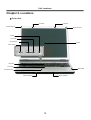
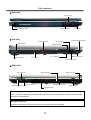
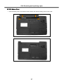
Service Manual (LS70) LG Electronics 0 Contents Ch 1. Service information Ch 2. Locations Ch 3. System information · Specification · Model configuration · System Block Diagram · Fn key combinations · Status indicators · BIOS Flash · BIOS Setup Ch 4. Symptom-to-part index · Power system checkout · Numeric error codes · Error messages · LCD-related symptoms · Indeterminate problems Ch 5. Removing and replacing a part (FRU) Ch 6. Part list · Part list · Exploded view 1 Ch1. Service information Chapter 1. Service information 1-1. Important service information Strategy for replacing parts (FRU-Field Replaceable Units) Before replacing parts Make sure that latest BIOS and drivers are installed before replacing any parts (FRUs) listed in this Use the following strategy to prevent unnecessary expense for replacing and servicing parts 1. If you are instructed to replacing a part but the replacement does not correct the problem, reinstall the original part before you continue. 2. Some computers have both a processor board and system board. If you are instructed to replace either the processor board or the system board, and replacing one of them does not correct the problem, reinstall that board, and then replace the other one. 3. If an adapter or device consists of more than one part, any of the parts (FRUs) may be the cause of the error. Before replacing the adapter or device, remove the parts (FRUs), one by one, to see if the symptoms change. Replace only the part that changed the symptoms. Caution The BIOS configuration on the computer you are servicing may have been customized. Running Automatic Configuration my alter the settings. Note the current configuration settings; then, when service has been completed, verify that those settings remain in effect. Strategy for replacing a hard-disk drive You have to get a User’s approval before formatting or replacing a hard-disk drive. You must let the User know that the user is responsible for the loss data Caution The drive startup sequence in the computer you are servicing may have been changed. Be extremely careful during write operations such as copying, saving, or formatting. If you select an incorrect drive, data or programs can be overwritten. 2 Ch1. Service information 1-2. Safety notices Warning Before the computer is powered-on after part (FRU) replacement, make sure all screws, springs, and other small parts are in place and are not left loose inside the computer. Verify this by shaking the computer and listening for rattling sounds. Metallic parts or metal flakes can cause electrical shorts. Warning some standby batteries contain a small amount of nickel and cadmium. Do not disassemble a standby battery, recharge it, throw it into fire or water, or short-circuit it. Dispose of the battery as required by local ordinances or regulations. Use only the battery in the appropriate parts listing. Use of an incorrect battery can result in ignition or explosion of the battery Warning The battery pack contains small amounts of nickel. Do not disassemble it, throw it into fire or water, or short-circuit it. Dispose of the battery pack as required by local ordinances or regulations. Use only the battery in the appropriate parts listing when replacing the battery pack. Use of an incorrect battery can result in ignition or explosion of the battery. Warning If the LCD breaks and the fluid from inside the LCD gets into your eyes or on your hands, immediately was the affected areas with water for at least 15 minutes. Seek medical care if any symptoms from the fluid are present after washing. Warning To avoid shock, do not remove the plastic cover that protects the lower part of the inverter card. Warning Though the main batteries have low voltage, a shorted or grounded battery can produce enough current to burn personnel or combustible materials. Warning Before removing any part (FRU), turn off the computer, unplug all power cords from electrical outlets, remove the battery pack, and then disconnect any interconnecting cables. 3 Ch1. Service information 1-3. Safety information General safety Follow these rules to ensure general safety · Observe good housekeeping in the area of the machines during and after maintenance. · When lifting any heavy object 1. Ensure you can stand safely without slipping. 2. Distribute the weight of the object equally between your feet. 3. Use a slow lifting force. Never move suddenly or twist when you attempt to lift. 4. Lift by standing or by pushing up with your leg muscles (This action removes the strain from the muscles in your back.) · Do not attempt to lift any object weights more then 16kg(35lb) or object that you think are too heavy for you. · Do not perform any action that causes hazards to the customer, or that makes the equipment unsafe. · Before you start the machine, ensure that other service representatives and the customer’s personnel are not in a hazardous position. · Place removed covers and other parts in a safe place, away from all personnel, while you are servicing the machine. · Keep your tool box away from walk areas so that other people will not trip over it. · Do not wear loose clothing that can be trapped in the moving parts of a machine. Make sure that your sleeves are fastened or rolled up above your elbows. If your hair is long, fasten it. · Insert the ends of your necktie or scarf inside clothing or fasten it with a nonconductive clip, approximately 8 centimeters(3 inches) from the end. · Do not wear jewelry, chains, metal-frame eyeglasses, or metal fasteners for you clothing. · Wear safety glasses when you are hammering, drilling, soldering, cutting wire, attaching springs, using solvents, or working in any other conditions that might be hazardous to your eyes. · After service, reinstall all safety shields, guards, labels, and ground wires. Replace any safety device that is worn or defective. · Reinstall all covers correctly before returning the machine to the customer. Caution Metal objects are good electrical conductors. 4 Ch1. Service information Electrical safety Observe the following rules when working on electrical equipment. Important Use only approved tools and test equipment. Some hand tools have handles covered with a soft material that does not insulate you when working with live electrical currents. Many customers have, near their equipment, rubber floor mats that contain small conductive fibers to decrease electrostatic discharges. Do not use this type of mat to protect yourself from electrical shock. · Find the room emergency power-off switch, disconnecting switch, or electrical outlet. If an electrical outlet. If an electrical accident occurs, you can then operate the switch or unplug the power cord quickly. · Do not work alone under hazardous conditions or near equipment that has hazardous voltages. · Disconnect all power before 1. Performing a mechanical inspection 2. Working near power supplies 3. Removing or installing main units · Before you start to work on the machine, unplug the power cord. If you cannot unplug it, ask the customer to power-off the wall box that supplies power to the machine and to lock the wall box in the off position. · If you need to work on a machine that has exposed electrical circuits, observe the following precautions : Ensure that another person, familiar with the power-off controls, is near you. Caution Another person must be there to switch off the power, if necessary. · Use only one hand when working with powered-on electrical equipment. Keep the other hand in your pocket or behind your back Caution An electrical shock can occur only when there is a complete circuit. By observing the above rule, you may prevent a current from through your body. · When using testers, set the controls correctly and use the approved probe leads and accessories for that tester 5 Ch1. Service information · Stand on suitable rubber mats (obtained locally, if necessary) to insulate you from grounds such as metal floor strips and machine frames. · Observe the special safety precautions when you work with very high voltages. These instructions are in the safety sections of maintenance information. Use extreme care when measuring high voltages. · Regularly inspect and maintain your electrical hand tools for safe operational condition. · Do not use worn or broken tools and testers. · Never assume that power has been disconnected from a circuit. First check that it has been powered off. · Always look carefully for possible hazards in your work area. Examples of these hazards are moist floors, non-grounded power extension cables, power surges, and missing safety grounds. · Do not touch live electrical circuits with the reflective surface of a plastic dental mirror. The surface is conductive such touching can cause personal injury and machine damage. · Do not service the following parts with the power on when they are removed from their normal operating places in a machine. 1. Power supply units 2. Pumps 3. Blowers and fans 4. Motorgenerators and similar units. (This practice ensure correct grounding of the units.) · If an electrical accident occurs 1. Use caution ; do not become a victim of yourself. 2. Switch off power. 3. Send another person to get medical aid. 6 Ch1. Service information Safety inspection guide The purpose of this inspection guide is to assist you in identifying potentially unsafe conditions. As each machine was designed and built, required safety items were installed to protect users and service personnel from injury. This guide addresses only those items. You should use good judgment to identify potential safety hazards due to attachment of non-LG features or options not covered by this inspection guide. If any unsafe conditions are present, you must determine how serious the apparent hazard could be and whether you can continue without first correcting the problem. · Consider these conditions and the safety hazards they present 1. Electrical hazards, especially primary power (primary voltage on the frame can cause serious or fatal electrical shock) 2. Mechanical hazards, such as loose or missing hardware Refer to the following checklist and begin the checks with the power off, and the power cord disconnected. · Checklist 1. Check exterior covers for damage (loose, broken, or sharp edges) 2. Power off the computer. Disconnect the power cord. 3. Check the power cord for : a. A third-wire ground connector in good condition. Use a meter to measure third-wire ground continuity for 0.1 or less between the external ground pin and frame ground. b. The power cord should be the type specified in the parts list. c. Insulation must not be frayed or worn. 4. Remove the cover. 5. Check for any obvious non-LG alterations. Use good judgment as to the safety of any non-LG alterations. 6. Check inside the unit for any obvious unsafe conditions, such as metal filings, contamination, water or other liquids, or signs of fire or smoke damage. 7. Check for worn, frayed, or pinched cables. 8. Check that the power-supply cover fasteners (screw or rivets) have not been removed or tampered with. 7 Ch1. Service information Handling devices that are sensitive to electrostatic discharge Any computer part containing transistors or integrated circuits (ICs) should be considered sensitive to electrostatic discharge (ESD). ESD damage can occur when there is a difference in charge between objects. Protect against ESD damage by equalizing the charge so that the machine, the part, the work mat, and the person handling the part are all at the same charge. Note Use product-specific ESD procedures when they exceed the requirements noted here. Make sure that the ESD protective devices you use have been certified (ISO9000) as fully effective. · When handling ESD-sensitive parts : 1. Keep the parts in protective packages until they are inserted into the product. 2. Wear a grounded wrist strap against your skin to eliminate static on your body. 3. Prevent the part from touching your clothing. Most clothing retains a charge even when you are wearing a wrist strap. 4. Use the black side of a grounded work mat to provide a static-free work surface. The mat is especially useful when handling ESD-sensitive devices. 5. Select a grounding system, such as those listed below, to provide protection that meets the specific service requirement. Note The use of a grounding system is desirable but not required to protect against ESD damage. a. Attach the ESD ground clip too any frame ground, ground braid, or green-wire ground. b. Use an ESD ground or reference point when working on a double-insulated or battery-operated system. You can use coax or connector-outside shells on these systems. c. Use the round ground-prong of the AC plug on AC-operated computers. Grounding requirements Electrical grounding of the computers is required for operator safety and correct system function. Proper grounding of the electrical outlet can be verified by a certified electrician. 8 Ch1. Service information 1-4. Laser compliance statement When a CD-ROM drive, DVD drive or the other laser product is installed, note the following : Caution Use of controls or adjustments or performance of procedures other than those specified here in might result in hazardous radiation exposure. Opening the CD-ROM drive, DVD-ROM drive or the other optical storage device could result in exposure to hazardous laser radiation. There are no serviceable parts inside those drives. Do not open Danger Emits visible and invisible laser radiation when open. Do not stare into the beam , do not view directly with optical instruments, and avoid direct exposure to the bean. 1-5. Backup (Standby) RTC battery safety information When replacing or disposing of the backup (standby) RTC battery, note the following : 9 Ch1. Service information 1-6. Read this first Before you go to the checkout guide, be sure to read this section. Important Notes · Only trained personnel certified by LG should service the computer. · Read the entire FRU removal and replacement page before replacing any FRU. · Use new nylon-coated screws when you replace FRUs. · Be extremely careful during such write operations as copying, saving, formatting. Drives in the computer that you are servicing sequence might have been altered. If you selected an incorrect drive, data or programs might be overwritten. · Replace FRUs only for the correct mode. · When you replace a FRU, make sure the model of the machine and the FRU part number are correct by referring to the FRU parts list. · A FRU should not be replaced because of a single, irreproducible failure. Single failures can occur for a variety of reasons that have nothing to do with a hard ware defect, such as cosmic radiation, electrostatic discharge, or software errors. · Consider replacing a FRU only when a problem recurs. If you suspect that a FRU is defective, clear the error log and run the test again. If the error does not recur, do not replace the FRU. · Be careful not to replace a non-defective FRU. What to do first You must fill out the record form first. During the warranty period, the customer may be responsible for repair costs if the computer damage was caused by misuse, accident, modification, unsuitable physical or operating environment, or improper maintenance by the customer. The following list provides some common items that are not covered under warranty and some symptoms that might indicate that the system was subjected to stress beyond normal use. Before checking problems with computer, determine whether the damage is covered under the warranty by referring to the following : 10 Ch1. Service information The followings are not covered under warranty : · CD panel cracked from the application of excessive force or from being dropped · Scratched (cosmetic) parts · Distortion, deformation, or discoloration of the cosmetic parts · Cracked or broken plastic parts, broken latches, broken pins, or broken connectors caused by excessive force · Damage caused by liquid spilled into system · Damage caused by improper insertion of a PC Card or the installation of an incompatible card · Damage caused foreign material in the diskette drive · Diskette drive damage caused by pressure on the diskette drive cover or by the insertion of a diskette with multiple labels · Damaged or bent diskette eject button · Fusses blown by attachment of a non-supported device · Forgotten computer password (making the computer unusable) · Sticky keys caused by spilling a liquid onto the keyboard The following symptoms might indicate damage caused by non-warranted activities : · Missing parts might be a symptom of unauthorized service or modification. · If the spindle of a hard-disk drive becomes noisy, it may have been subjected to excessive force, or dropped. 11 Ch2. Locations Chapter 2. Locations Front view LCD latch LCD latch WLAN Antenna WLAN Antenna MUTE Volume Up Volume Down LCD Power switch Keyboard TouchPad Built-in MIC TouchPad button Built-in speaker Built-in speaker 12 Ch2. Locations Rear view LAN connector S-VIDEO connector Modem connector Left view Parallel connector USB connector PC Card slot AC connector Express Card eject button Express Card slot 4-in-1 Card slot VGA connector IEEE1394 connector Fan louvers PC Card eject button Right view MIC connector Security key hole ODD eject button Line-in connector Headphone connector Emergency eject hole USB connector Optical Disk Drive Security key hole (Kensington Lock) User can attach a separately purchased chain lock into the security keyhole and connect it to a fixed object to prevent a notebook theft Emergency eject hole Insert a thin and hard pin into this hole, and you can open the disc tray manually. 13 Ch3. System information Chapter 3. System information Specification - CPU · Dothan 1.6 ~ 2.1 GHz · μFCBGA - Main Chipset & Graphic · Intel 915GM,ICH6-M · Intel 915PM, ICH6-M, ATI Mobility Radeon X600 VGA Controller - Memory · 2SODIMM – Up to 2GB · DDR2 PC2-3200S/4200S Capable (400/533MHz) - HDD · 2.5” 9.5mm 40/60/80GB SATA Type - Communication · Modem, Daughter Card Type · Marvell Yukon PCI-E Gigabit Ethernet Controller on Board - Wireless LAN Solution · 802.11bg/abg Mini PCI Type, Quad-band Antenna - Card Slot · Express Card Slot · 4-in-I Card Slot (Memory Stick, Memory Stick Pro, Multi Media Card, SD Card) - ODD · Fixed Optical Storage · DVD-COMBO - Port · VGA, 3X USB(2.0), RJ11, RJ45, Headphone-out/SPDIF, Mic-in, AC-in, IEEE1394, S-Video - Input Devices · Keyboard : 86Key Keyboard · Touchpad - Buttons · Power, Volume Down, Volume Up, Mute - Indicator (LED) · AC-in, Power On, Charge, HDD, Caps Lock, Num Lock, Wireless - Power · 90 Watt 19V 4.74A Adapter - Audio · C-Media Azalia Audio Codec, Stereo speakers each 0.5/0.8W - Battery · 6 Cell 4.8AHr, CYLINDRICAL (Li-Ion) · 9 Cell 7.2AHr, CYLINDRICAL (Li-Ion) 14 Ch3. System information System Block Diagram 15 Ch3. System information Fn key combinations The following table shows the function of each combination of Fn with a function key. Function of Fn keys has nothing to do with Operating System. [Fn] + Description [F1] User-defined Hot key. (Setting is available at OSD) [F2] User-defined Hot key. (Setting is available at OSD) [F3] User-defined Hot key. (Setting is available at OSD) [F4] Force the computer to enter power-saving mode. (ex: system standby and hibernation) [F5] TouchPad Disable (Impossible to use TouchPad) / TouchPad Enable (Possible to use TouchPad) / TouchPad Auto-Disable (When connecting USB mouse to the computer, TouchPad is disable) The TouchPad initialization takes 1~2 seconds, so wait for the Initialization to end before using the TouchPad. [F6] Wireless LAN on / off [F7] When the computer is attached to an external monitor, you can changed the display output location with [Fn] + [F7] combination. You can switch to and from the three types of display modes, LCD display only, the external monitor only, or both at the same time. [F8] Enable/Disable Auto Sound power management (battery mode only). [F9] Enable/Disable Auto Brightness control. [F10] System information [ESC] Maximum power-saving mode. (when OSD is installed) [ScrLk] Number lock [Delete] Brightness up [Insert] Brightness down PgUp PgDn Home End [F12] Maximum power-saving mode. 16 Ch3. System information Status indicators The system status indicators show the status of the computer 1 3 2 4 5 6 7 1. Caps lock Caps lock indicator lights up when the Caps lock key is pressed. When this indicator lights up, you can type capital letters without pressing the Shift key. 2. Num lock Num lock indicator lights up when the combination of the Fn and Num lock key is pressed. When this indicator lights up, you can use the embedded numeric keys. (To use the numeric keys, you must enable the Internal Keypad setting under the Advanced menu in the BIOS Setup Utility.) 3. Wireless activity indicator Wireless activity indicator indicates the following. Off: Wireless LANis off. Blinking(3-4 Seconds): Searching for Access point for Wireless LAN Connection. Blinking (short interval): Data is transferring with Wireless LAN is on. 4. AC Power Power indicator lights up when the power cord is connected to the computer. 5. Power Power status indicator indicates the following status of the computer. Green: The computer is turned on. Off: The computer is turned off or is in hibernation mode. Blinking: The computer is in standby mode. 6. Battery Battery status indicator indicates the following status of the battery. Green: The computer is connected to an AC adaptor and is being charged. Off: The battery is fully charged OR the computer is not connected to an AC Adapter. Blinking: The battery power is under 10% of its maximum capacity or battery occurs. Battery tribe warning blinks as user defined from 'Battery Miser'. 7. Drive in use Drive in use indicator lights up when data is being written to or read from the hard disk or optical disk drive. 17 Ch3. System information BIOS Flash You can update BIOS using a floppy disk drive. Because this system is not equipped with any floppy disk drive, you have to use an external USB drive for a BIOS update. In order to boot up with an USB drive, please set Removable Device as the first boot up drive in the boot menu of BIOS setup. · How to update flash ROM in DOS 1. Create ‘boot up’ flash update diskette. 2. Copy a ROM image file (*.wph) into the root of the flash update diskette. 3. Copy phlash16.exe to the flash update diskette. 4. Insert the diskette into the FDD of your computer. 5. Boot your computer with the diskette, and type ‘phlash16*.wph/mode=n’. 6. Cold boot and follow the instruction displayed on the screen. · Flash options /mode=n 0 – Default mode. Keep the current DMI information and update BIOS image only. 1 – Update DMI information only. If new DMI information is not specified, the current DMI information is left unchanged. 2 – Update BIOS and DMI information. If new DMI information is not specified, the current DMI information is left unchanged. 3 – Update BIOS and DMI information. DMI information is updated to the DMI string and options specified in the new BIOS image. Note DMI is Desktop Management Interface 18 Ch3. System information How to update flash ROM in Windows 1. Quit all running programs. 2. Start WINPHLASH.EXE. 3. Select the procedure you want : a. Backup BIOS and Flash BIOS with new settings b. Backup BIOS Only 4. Specify the locations for backup and new BIOS files in BIOS Setting Locations. a. Enter the name of the backup file for existing BIOS or click Browse to locate the file. b. Enter the name of the new BIOS file or click Browse to locate the file. 5. Click Advanced Settings button to access the advanced settings 6. Click Flash BIOS button to start flash BIOS. 7. Wait for the operation to complete. WinPhlash may take one or two minutes to complete flash BIOS operation. 19 Ch3. System information 8. After the completion, ‘System BIOS was successfully updated’ appears on the screen, then the computer restarts. 9. After the restart, make sure the system BIOS is updated. 10. If your computer does not restart automatically, turn off your computer and then turn it back on by pressing power button. 20 Ch3. System information BIOS Setup BIOS (Basic Input and Output System) Setup saves the system configuration in CMOS RAM, and check the configurations during startup. Use the BIOS Setup Utility to change and save the system environment, hardware configurations, power saving mode, etc. · Open the BIOS Setup Utility in the following situations : 1. to change the BIOS setup 2. to replace the backup battery 3. system configuration error occurs 4. to change the boot order 5. to set/change a password Press the power button. When the LG logo appears on the screen, press and enter the BIOS Setup Utility. 21 Ch3. System information Using the keys The keys used in the BIOS Setup Utility and their functions are described at the bottom. · , + : General Help Display the descriptions of the keys used in the setup utility. · , : Select Item Navigate and select items in the setup utility. The selected item becomes highlighted. · , : Select Menu Move to another menu. · / , : Change Values Change the value of a selected item. · : Load Default Configuration Display Setup Confirmation window. Press Enter to load default configuration. · : Select Sub-Menu Some items have sub-menus. Display the sub-menu for a selected item. · : Save and Exit Display Setup Confirmation window. Press Enter to save and exit. · : Exit In a sub-menu, press Esc to move to the previous window. In Main menu, click Esc to move to Exit menu. 22 Ch3. System information Main menu System Time Current time. Use <Tab>, <Shift-Tab>, or <Enter> keys to move around these fields. To change the value, press <+> or <−> key. System Date Today date. Use <Tab>, <Shift-Tab>, or <Enter> keys to move around these fields. To change the value, press <+> or <−> key. Set any date from year 1981 to 2079. It will automatically keep track of leap years. The system date can also be set from the operating system. Product Name This shows the name of PC. Processor Type This shows the type of CPU. Processor Spd This shows the speed CPU. BIOS Version This shows the Version of BIOS. KBC Version This shows the Version of KBD firm ware. UUID This is for display only. This shows the UUID. Pri Master Enter its submenu by pressing <Enter>. In this submenu, it would show the device of Primary IDE Master is HDD and its parameters. Pri Slave Enter its submenu by pressing <Enter>. In this submenu, it would show the device of Primary IDE Slave is HDD and its parameters. Sec Master Enter its submenu by pressing <Enter>. In this submenu, it would show the device of Secondary IDE Master is optical drive and its parameters. Sec Slave Enter its submenu by pressing <Enter>. In this submenu, it would show the device of Secondary IDE Slave is optical drive and its parameters. System Memory This is for display only. This shows size of system memory. Ext. Memory This is for display only. This shows size of extended memory. 23 Ch3. System information Advanced menu Legacy USB Support There are two options to this field: Enabled, and Disabled. This field allows you to enable or disable the legacy USB support. Boot-time Diagnostic Screen Enables the Boot-time Diagnostic Screen. SATA Controller Mode Set SATA (Serial ATA) Controller Mode. AHCI Configuration Enables the AHCI (Advanced Host Controller Interface). Battery Charge Stop Percentage Set Battery Charge Stop Percentage. Fan Mode Control Set Fan Mode Control. Fn Key Setup Set Sticky fn key function. Wake On Lan Enables Wake On Lan. PXE/Remote Boot Enables PXE/Remote Boot. Execute-Disable Bit Capability Enables Execute-Disable Bit Capability. Security menu Supervisor Password Is This shows the system’s supervisor password has been set, or not. Set Supervisor Password Set Supervisor Password. User Password Is This shows the system’s User Password has been set, or not. Set User Password Set User Password. Password on boot Enables Password on boot. HDD Password Is This shows the system’s HDD Password has been set, or not. Set HDD Password Set HDD Password. 24 Ch3. System information Boot menu Boot menu enables you to set the boot order for the CD-ROM drive, Removable devices Hard drive, and Network boot as shown below. CD-ROM Drive Removable Devices Hard Drive B2 D0 Yukon PXE Exit menu Exit Saving Changes Select Exit Saving Changes to save new setup information in CMOS RAM. CMOS RAM stores the information using the backup battery; therefore, the information will not be lost when the computer is turned off. Exit Discarding Changes Select Exit Discarding Changes to discard new setup information. If you made changes to items other than date, time, and passwords, the Setup Warning asks you to save the new configurations. Select Yes and press Enter to save the new configuration. Load Setup Defaults Select Load Setup Defaults to change the setup information to the factory default settings. If you select Load Setup Defaults or press F9, Setup Confirmation asks you to confirm your selection. Press Yes to load setup defaults. Discard Changes Discard change value. Save Changes Save change value. 25 Ch4. Symptom-to-part index Chapter 4. Symptom-to-part index The symptom-to-part index in this section lists symptoms and errors and their possible causes. The most likely cause is listed first. Note If replacing a part (FRU) does not solve the problem, put the original part back in the computer. Do not replace a non-defective FRU. Power system checkout · To verify a symptom, do the following : 1. Power off the computer. 2. Remove the battery pack. 3. Connect the AC adapter. 4. Check that power is supplied when you power on the computer. 5. Power off the computer. 6. Disconnect the AC adapter and install the charged battery pack. 7. Check that the battery pack supplies power when you power on the computer. · If you suspect a power problem, see the appropriate one of the following power supply checkouts : 1. Checking the AC adapter 2. Checking the operational charging 3. Checking the battery pack 4. Checking the backup battery · Checking the AC adapter If the power-on indicator does not turn on, check the power cord of the AC adapter for correct continuity and installation. If the computer does not charge during operation, go to “Checking operational charging.” To check the AC adapter, do the following : 1. Unplug the AC adapter cable from the computer. 2. Measure the output voltage at the plug of the 2 1 AC adapter cable. See the following figure : 26 Pin Voltage (V dc) 1 +18.05 ~ +19.95 2 Ground Ch4. Symptom-to-part index · If the voltage is not correct, replace the AC adapter. · If the voltage is acceptable, do the following : 1. Replace the system board. 2. If the problem persists, check the AC adapter whether it is correct product or not. Note Noise from the AC adapter does not always indicate a defect. · Checking operational charging 1. To check whether the battery charges properly during operation, use a discharged battery pack or a battery pack that has less than 50% of the total power remaining when installed in the computer. Perform operational charging. If the battery status indicator or icon does not turn on, remove the battery does not turn on, replace the battery pack. 2. If the charge indicator still does not turn on, replace the system board. Then reinstall the battery pack. Note Do not charge battery pack, when its temperature is below 0 or above 75 . · Checking the battery pack 1. Open the Power Meter window by clicking Start Control Panel Power Options and then; check the total power remains. Battery charging does not start until the power Meter shows that less than 95% of the total power remains; under this condition the battery pack can charge to 100% of its capacity. This protects the battery pack from being overcharged or from having a shortened life. 2. To check the status of your batter, move your cursor to the Power Meter icon in the icon tray of the Windows taskbar and wait for a moment (but do not click), and the percentage of battery power remaining is displayed. To get detailed information about the battery, double-click the Power Meter icon. Note If the battery pack becomes hot, it may not be able to charge. Remove it from the computer and Leave it at room temperature for a while. After it cools down, reinstall and recharge it. 27 Ch4. Symptom-to-part index · The Characteristics of the battery pack 1. Self-discharge The battery gradually loses its power over time without ever being used. 2. Periodic full discharge / charge Frequent recharge of the battery pack can reduce the capacity of the battery pack. When this happens, you can perform the full discharge / charge to improve the capacity. You should perform periodic full discharge /charge once every 30~60 days. You should always use the battery until its power is low; then fully charge the battery. 3. Trickle charge If the temperature of the battery pack drops below 10 , the trickle charging begins. The trickle charging may take 32 hours for the battery pack to be fully charged. 28 Ch4. Symptom-to-part index · To check the battery pack, do the following : 1. Power off the computer. 2. Remove the battery pack and measure the voltage between battery terminals 1(-) and 5(+). See the following figure : 5(+) 4 3 2 Terminal Voltage (V dc) 1 Ground(-) 5 +0V ~ +12.6V (6 cell) 1(-) 3. If the voltage is still less than +11.1 V DC after recharging, replace the battery. 4. If the voltage is more than +11.1 V DC, measure the resistance between battery terminals 1 and 2. The resistance must be 2 to 4 (typically 3 ). 5. If the resistance is not correct, replace the battery pack. If the resistance is correct, replace the system board. Note Charging will take at least 3 hours. Note Battery is an expendable supplier, so its capacity and used time can be reduced by using the computer. 29 Ch4. Symptom-to-part index Numeric error codes Symptom / Error FRU or action, in sequence 0200 Fixed disk failure (The hard disk is not working) 1.Reset the hard-disk drive. 2.Load Setup Defaults in BIOS Setup Utility. 3.Hard-disk drive. 4.System board. 0210 Stuck Key error 1.Check the keyboard if it is pressed. 2.Replace the keyboard. 0211 Keyboard error Run interactive tests of the keyboard and the auxiliary input device. 0212 Keyboard Controller Failed System board. 0220 Monitor type error - Monitor type does not match the one specified in CMOS. Load Setup Defaults in BIOS Setup Utility. 0230 System RAM error - System RAM Failed at offset. 1.DIMM 2.System board 0231 Shadow RAM error - Shadow RAM failed at offset System board 0232 Extended RAM error - Extended RAM Failed at address line 1. DIMM 2. System board 0250 System battery error – System battery is dead Replace the backup battery and run BIOS Setup Utility to reset the time and date. 30 Ch4. Symptom-to-part index Symptom / Error FRU or action, in sequence 0251 System CMOS checksum bad – System CMOS checksum is not correct. – Default configuration used. Replace the backup battery and run BIOS Setup Utility to reset the time and date. 0252 Password checksum bad – The password is cleared. Reset the password by running BIOS Setup Utility. 0260 System timer error 1. Replace the backup battery and run BIOS Setup Utility to reset the time and date. 2. System board. 0271 Check date and time settings – Date and time error. Run BIOS Setup Utility to reset the time and date. 0280 Previous boot incomplete - Default configuration used 1. Load “Setup Default” in BIOS Setup Utility. 2. DIMM. 3. System board. 0281: Memory Size found by POST differed from EISA CMOS Load Setup Defaults in BIOS Setup Utility. 02B0 Diskette drive A error Set up the diskette type in BIOS Setup Utility. 02B1 Diskette drive B error Set up the diskette type in BIOS Setup Utility. 02B2 Incorrect drive A type – Floppy diskette drive error 1. Floppy diskette drive. 2. External FDD cable. 3. I/O card. 02B3 Incorrect Drive B type 1. Floppy diskette drive. 2. External FDD cable. 3. I/O card. 02D0 System cache error – Cache disabled (RAM cache failed and BIOS disabled) 1. Load “Setup Default” in BIOS Setup Utility. 2. System board. 02F4 EISA CMOS not writable 1. Load “Setup Default” in BIOS Setup Utility. 2. Replace the backup battery. 3. System board. 02F5 DMA test failed 1. DIMM 2. System board 02F6 Software NMI failed 1. DIMM 2. System board 31 Ch4. Symptom-to-part index Symptom / Error FRU or action, in sequence 02F7 Fail – Safe timer NMI failed 1. DIMM 2. System board 0611 IDE configuration changed 1. Load Setup Defaults in BIOS Setup Utility. 2. System board. 0612 IDE configuration error 1. Load Setup Defaults in BIOS Setup Utility. 2. System board. 0613 Com A configuration changed 1. Load Setup Defaults in BIOS Setup Utility. 2. System board. 0614 Com A configuration error 1. Load Setup Defaults in BIOS Setup Utility. 2. System board. 0615 Com B configuration changed 1. Load Setup Defaults in BIOS Setup Utility. 2. System board. 0616 Com B configuration error 1. Load Setup Defaults in BIOS Setup Utility. 2. System board. 0617 Floppy configuration changed 1. Load Setup Defaults in BIOS Setup Utility. 2. System board. 0618 Floppy configuration error 1. Load Setup Defaults in BIOS Setup Utility. 2. System board. 0619 Parallel port configuration changed 1. Load Setup Defaults in BIOS Setup Utility. 2. System board. 061A Parallel port configuration error 1. Load Setup Defaults in BIOS Setup Utility. 2. System board. 32 Ch4. Symptom-to-part index Error message Symptom / Error FRU or action, in sequence Device address conflict. 1. Load Setup Defaults in BIOS Setup Utility. 2. Backup battery. 3. System board. Allocation error for device. 1. Load Setup Defaults in BIOS Setup Utility. 2. Backup battery. 3. System board. Failing bits: nnnn. 1. DIMM. 2. System board. Invalid System Configuration Data. 1. DIMM. 2. System board. I/O Device IRQ Conflict. 1. Load Setup Defaults in BIOS Setup Utility. 2. Backup battery. 3. System board. Operating System not found. 1. Check that the operating system has no failure and is installed correctly. 2. Enter BIOS Setup Utility and see whether the hard -disk drive and the diskette drive are properly identified. 3. Reset the hard-disk drive. 4. Reinstall the operating system. 5. Diskette drive. 6. Hard-disk drive. 7. System board. Hibernation error. 1. Restore the system configuration to what it was before the computer entered hibernation mode. 2. If memory size has been changed, re-create the hibernation file. FAN error. Fan. Thermal sensing error. System board. 33 Ch4. Symptom-to-part index LCD-related symptoms Note Before removing or disassembling LCD, power off the computer, unplug all power cords from electrical outlets, remove the battery pack also. Symptom / Error FRU or action, in sequence LCD screen becomes dark suddenly. Check out Battery Miser. Nothing displayed on LCD screen. 1. Check out Battery Miser. 2. Choose Never in the Turn off Monitor item on Power Options Properties. 3. Check the power save mode switch if it is pressed by something. 4. Check the System is in standby or hibernation mode. LCD backlight not working. LCD too dark. LCD brightness cannot be adjusted. 1. Reconnect inverter to the board connector. 2. Replace inverter. 3. LCD assembly. 4. System board. LCD color cannot be adjusted. LCD screen abnormal. Characters missing pixels. LCD screen unreadable. Wrong color displayed. 1. Reset all LCD connectors. 2. Replace LCD cable. 3. LCD assembly. 4. System board. Horizontal or vertical lines displayed on LCD LCD assembly. Power-on indicator on, and a blank\LCD during POST. LCD assembly. System board. 34 Ch4. Symptom-to-part index Indeterminate problems · You are here because the diagnostic tests did not identify which adapter or device failed, wrong devices are installed, a short circuit is suspected, or the system is inoperative. Follow these procedures to isolate the failing FRU (do not isolate FRUs that have no defects). · Verify that all attached devices are supported by the computer. · Verify that the power supply being used at the time of the failure is operating correctly. 1. Power off the computer 2. Visually check each FRU for damage. Replace any damaged FRU. 3. Remove or disconnected all of the following devices : a. Non-LG devices. b. Printer, mouse, and other external devices. c. Battery pack. d. PC cards. e. ODD (CD-ROM, Combo) drive or FDD drive in the Bay. f. Hard-disk drive. Note Use the other memory card because it needs when operating computer. 4. Power on the computer. 5. Determine whether the problem has changed. 6. If the problem does not recur, reconnect the removed devices one at a time until you find the failing FRU. 7. If the problem remains, replace the following FRUs one at a time. (do not replace a non-defective FRU) a. LCD assembly (Check external monitor whether the same problem recurs or not). b. Keyboard. c. Keydeck (TouchPad and Scroll Button assembly). d. System board. 35 Ch5. Removing and replacing a part Chapter 5. Removing and replacing a part (FRU) Danger Before removing any FRU, power off the computer, unplug all power cords from electrical outlets, remove the battery pack, and then disconnect any interconnecting cables. Caution Before the computer is powered on after FRU replacement, make sure that all screws, springs, and other small parts are in place and are not loose inside the computer. Verify metal flakes can cause electrical short circuits. Note As for the screw, every Torque 3 0.2Kgfcm(0.196Nm) 36 Ch5. Removing and replacing a part ■ 1010 Battery Pack 1. Push the battery latch in the direction shown below; then side the battery pack out of the slot. 37 Ch5. Removing and replacing a part ■ 1020 Hard Disk Drive Remove the following parts in order before replacing this part 1. Battery Pack(1010) 2. Battery Pack(1010) 1. Remove a screw as indicated in the picture, then pull the HDD Assy out in the direction shown below. No. FRU No. Specification Qty 1 1SZZBA4063B M2.5 X L3.5 2 38 Ch5. Removing and replacing a part ■ 1030 Wireless LAN Card Remove the following parts in order before replacing this part 1. Battery Pack(1010) 2. Hard Disk Drive(1020) 3. Keyboard(1030) 1. Remove 3 Memory Cover screws. No. FRU No. Specification Qty 1 1SZZBA4063A M2.5 X L3.5 3 2. Remove WLAN Card Antenna cable. Remove WLAN Card. 39 Ch5. Removing and replacing a part ■ 1040 Keyboard Remove the following parts in order before replacing this part 1. Battery Pack(1010) 2. Hard Disk Drive(1020) 3. W/L LAN Card(1030) 1. Remove 2 screws. No. FRU No. Specification Qty 1 1SZZBA4097A M2.5 X L6.5 2 2. To remove 3 hooks, insert a (-) type screwdriver into a hook located at the lower end of keyboard, and pull it up. 40 Ch5. Removing and replacing a part 3. Disconnect Keyboard Connector and remove Keyboard. 41 Ch5. Removing and replacing a part ■ 1050 Retainer Remove the following parts in order before replacing this part 1. Battery Pack(1010) 2. Hard Disk Drive(1020) 3. W/L LAN Card(1030) 4. Keyboard(1040) 1. Remove 2 screws. No. FRU No. Specification Qty 1 1SZZBA4097A M2.5 X L6.5 2 2. To remove Retainer, insert a (-) type screwdriver into a hook located at the lower end of keyboard, and pull it up. 42 Ch5. Removing and replacing a part 3. Disconnect Retainer Connector and remove Retainer. 43 Ch5. Removing and replacing a part ■ 1060 Keyboard Plate Remove the following parts in order before replacing this part 1. Battery Pack(1010) 2. Hard Disk Drive(1020) 3. W/L LAN Card(1030) 4. Keyboard(1040) 5. Retainer(1050) 1. Remove 7 screws and remove Keyboard Plate. No. FRU No. Specification Qty 1 1SZZBA4023A M2.0 X L3.5 7 44 Ch5. Removing and replacing a part ■ 1070 FAN Assembly Remove the following parts in order before replacing this part 1. Battery Pack(1010) 2. Hard Disk Drive(1020) 3. W/L LAN Card(1030) 4. Keyboard(1040) 5. Retainer(1050) 6. Keyboard plate(1060) 1. Remove 4 screws and remove Fan Module. 1 1 2 1 No. FRU No. Specification Qty 1 1SZZBZ4020A M2.0 X L10.0 3 2 1SZZBZ4014A M2.0 X L5.0 1 45 Ch5. Removing and replacing a part ■ 1080 Hinge Cover Remove the following parts in order before replacing this part 1. Battery Pack(1010) 2. Hard Disk Drive(1020) 3. W/L LAN Card(1030) 4. Keyboard(1040) 5. Retainer(1050) 6. Keyboard plate(1060) 7. Keyboard plate(1070) 1. Using a screw driver, remove Hinge Cover. (Left / Right) 46 Ch5. Removing and replacing a part ■ 1090 Display Module Remove the following parts in order before replacing this part 1. Battery Pack(1010) 2. Hard Disk Drive(1020) 3. W/L LAN Card(1030) 4. Keyboard(1040) 5. Retainer(1050) 6. Keyboard plate(1060) 7. Keyboard plate(1070) 8. Hinge Cover(1080) 1. Remove 2 screws. No. FRU No. Specification Qty 1 1SZZBA4039B M2.5 X L8.0 2 No. FRU No. Specification Qty 1 1SZZBA4097A M2.5 X L6.5 2 2. Remove 2 screws. 47 Ch5. Removing and replacing a part 3. Remove Display Module. 48 Ch5. Removing and replacing a part ■ 110 0 Key Deck Remove the following parts in order before replacing this part 1. Battery Pack(1010) 2. Hard Disk Drive(1020) 3. W/L LAN Card(1030) 4. Keyboard(1040) 5. Retainer(1050) 6. Keyboard plate(1060) 7. Keyboard plate(1070) 8. Hinge Cover(1080) 9. Display Module(1090) 1. Remove 14 screws. 3 1 3 1 2 1 1 1 3 3 1 1 1 1 No. FRU No. Specification Qty 1 1SZZBA4097A M2.5 X L6.5 9 2 1SZZBA4039B M2.5 X L8.0 1 3 1SZZBA4017A M2.0 X L3.0 4 49 Ch5. Removing and replacing a part 3. Remove 4 screws from Key Deck. Disconnect TouchPad cable and speaker cable. No. FRU No. Specification Qty 1 1SZZBZ4014A M2.0 X L5.0 4 50 Ch5. Removing and replacing a part ■ 1110 Optical Disk Drive Remove the following parts in order before replacing this part 1. Battery Pack(1010) 2. Hard Disk Drive(1020) 3. W/L LAN Card(1030) 4. Keyboard(1040) 5. Retainer(1050) 6. Keyboard plate(1060) 7. Keyboard plate(1070) 8. Hinge Cover(1080) 9. Display Module(1090) 10. Display Module(1100) 1. Insert a screwdriver into the hole located at the rear of ODD and push it out. 51 Ch5. Removing and replacing a part ■ 1120 Audio Board Remove the following parts in order before replacing this part 1. Battery Pack(1010) 2. Hard Disk Drive(1020) 3. W/L LAN Card(1030) 4. Keyboard(1040) 5. Retainer(1050) 6. Keyboard plate(1060) 7. Keyboard plate(1070) 8. Hinge Cover(1080) 9. Display Module(1090) 10. Display Module(1100) 11. Optical Disk Drive(1110) 1. Remove 2 screws. Disconnect Audio connector and remove Audio Board. No. FRU No. Specification Qty 1 1SZZBA4023A M2.0 X L3.5 2 52 Ch5. Removing and replacing a part ■ 1130 HDD Cover Block (L) Remove the following parts in order before replacing this part 1. Battery Pack(1010) 2. Hard Disk Drive(1020) 3. W/L LAN Card(1030) 4. Keyboard(1040) 5. Retainer(1050) 6. Keyboard plate(1060) 7. Keyboard plate(1070) 8. Hinge Cover(1080) 9. Display Module(1090) 10. Display Module(1100) 11. Optical Disk Drive(1110) 12. Audio Board(1120) 1. Remove HDD Cover Block as indicated in the picture. 53 Ch5. Removing and replacing a part ■ 1140 Hinge Frame (L) Remove the following parts in order before replacing this part 1. Battery Pack(1010) 2. Hard Disk Drive(1020) 3. W/L LAN Card(1030) 4. Keyboard(1040) 5. Retainer(1050) 6. Keyboard plate(1060) 7. Keyboard plate(1070) 8. Hinge Cover(1080) 9. Display Module(1090) 10. Display Module(1100) 11. Optical Disk Drive(1110) 12. Audio Board(1120) 13. HDD Cover Block(1130) 1. Remove 2 screws. Remove Hinge Frame (Left). No. FRU No. Specification Qty 1 1SZZBZ4014A M2.0 X L5.0 2 54 Ch5. Removing and replacing a part ■ 1150 Main Board Remove the following parts in order before replacing this part 1. Battery Pack(1010) 2. Hard Disk Drive(1020) 3. W/L LAN Card(1030) 4. Keyboard(1040) 5. Retainer(1050) 6. Keyboard plate(1060) 7. Keyboard plate(1070) 8. Hinge Cover(1080) 9. Display Module(1090) 10. Display Module(1100) 11. Optical Disk Drive(1110) 12. Audio Board(1120) 13. HDD Cover Block(1130) 14. Hinge Frame (L)(1140) 1. Remove 3 screws. Disconnect RTC Battery and S-VIDEO connector. Remove Main Board. No. FRU No. Specification Qty 1 1SZZBA4023A M2.0 X L3.5 3 55 Ch5. Removing and replacing a part 56 Ch5. Removing and replacing a part 57 Ch5. Removing and replacing a part ■ 1150 S-Video Board Remove the following parts in order before replacing this part 1. Battery Pack(1010) 2. Hard Disk Drive(1020) 3. W/L LAN Card(1030) 4. Keyboard(1040) 5. Retainer(1050) 6. Keyboard plate(1060) 7. Keyboard plate(1070) 8. Hinge Cover(1080) 9. Display Module(1090) 10. Display Module(1100) 11. Optical Disk Drive(1110) 12. Audio Board(1120) 13. HDD Cover Block(1130) 14. Hinge Frame (L)(1140) 14. Main Board(1150) 1. Remove RTC BATT and S-VIDEO Board. 1 2 No. FRU No. Specification Qty 2 1SZZBZ4014A M2.0 X L5.0 1 2 1SZZBA4023A M2.0 X L3.5 1 58 Ch5. Removing and replacing a part ■ 1100 Display Module Remove the following parts in order before replacing this part 1. Using a knife, remove the logo and rubbers that are covering the screws. Then remove all 6 screws. No. FRU No. Specification Qty 1 1SZZBA4080F M2.5 X L4.5 6 59 Ch5. Removing and replacing a part 2. Disassemble the LCD front. The front hook located on the middle of LCD upper and lower end. Be careful of the direction when removing because it is connected from inside out. 60 Ch5. Removing and replacing a part 3. Remove 5 screws and disconnect Inverter Cable. 1 1 1 1 2 No. FRU No. Specification Qty 1 1SZZBA4080F M2.5 X L4.5 4 2 1SZZBZ3002W M2.5 X L3.5 1 61 Ch5. Removing and replacing a part 4. Remove WLAN Antenna Cable. Press the hook on the both side of LCD with a (-) type screwdriver and remove from the LCD rear panel. 62 Ch5. Removing and replacing a part 5. Remove 6 screws. Remove LCD from the LCD rear panel. 1 1 2 2 2 2 No. FRU No. Specification Qty 1 1SZZBA4080F M2.5 X L4.5 2 2 1SZZBA4017A M2.0 X L3.0 4 63 Ch6. Part lists Chapter 6. Part lists 2005-01-31 Specification HTF05 Location Part Number Remarks HFL01 6304FLP080A LP150E06-A2 LG PHILPS TFT COLOR 15.0 INCH SXGA+(1400X1050) ISP STYLE B WVA LCD 단품 HFL01 6304FLP081B LP150E06-A3 LG PHILPS TFT COLOR 15.0 INCH SXGA+(1400X1050) ISP STYLE B WVA P3 PLANT LCD 단품 HFL01 6304FHS008A HSD150PK17-A00 HANNSTAR TFT COLOR 15.0 INCH SXGA+(1400X1050) WVA ISP STYLE B LCD 단품 HFL02 3111B0TS53A HUNTER-FULL 15 INCH COVER REAR ASSY REAR CASE HFL03 3300BP1079A PLATE, DISPLAY REAR HUNTER 150 FULL . PLATE DISPLAY HFL04 4940BM4166A Knob, latch HFL05 4970BW4556A Spring, Latch SPRING HFL06 3111B0TS24A Case Assy, Front 15.0" FRONT CASE HFL07 4774BD2005A Hinge Ass'y-L HINGE LEFT HFL08 4774BD2006A Hinge Ass'y,-R HINGE RIGHT HFL09 3300BP4455A Plate, Inverter Inverter Plate HFL10 3301B00540A Plate, antenna-L (620mm) Antenna Left HFL11 3301B00541A Plate, antenna-R (800mm) Antenna Right HFL12 6708BI0088A KUBNKM095A ALPS INVERTER Inverter HFL12 6708BI0089A DAC-08B073 DELTA HUNTER-TL 15 INCH OZ1060S Inverter HFL13 4850BM4029A Cushion, rubber-upper Cushipn upper HFL14 4826BZ4003B Cushion, rubber-middle Cushion Middle HFL15 4850BM4030A Cushion, rubber-lower Cushion Bottom HFL16 6851B34028A LCD Cable Assy(XGA),Tae-yang LCD Cable HFL16 6851B34032A LCD Cable Assy(XGA), Washin LCD Cable HFL16 6851B34029A LCD Cable Assy(SXGA),Tae-yang LCD Cable HFL16 6851B34033A LCD Cable Assy(SXGA), Washin LCD Cable HFL17 3850BB3042A Label, front brand name label Logo Lable HFL18 3858BP4273A Logo Badge (X-Note) BADGE HFL18 3858BZ4462A Logo Badge (LG) BADGE HFB01 6871BH700A1 HUNTER-FULL 15 INCH LGE 10 LAYERS (REV 0.7A) PP MAIN B/D ASSY(PM128+GB) KNOB 64 M/B Assy Ch6. Part lists Location Part Number Specification Remarks HFB01 6871BH710A1 HUNTER-FULL 15 INCH LGE 10 LAYERS (REV 0.7A) PP MAIN B/D ASSY(PM64+GB) M/B Assy HFB01 6871BH720A1 HUNTER-FULL 15 INCH LGE 10 LAYERS (REV 0.7A) PP MAIN B/D ASSY(PM64+FE) M/B Assy HFB01 6871BH730A1 HUNTER-FULL 15 INCH LGE 10 LAYERS (REV 0.7A) PP MAIN B/D ASSY(GM+GB) M/B Assy HFB01 6871BH740A1 HUNTER-FULL 15 INCH LGE 10 LAYERS (REV 0.7A) PP MAIN B/D ASSY(GM+FE) M/B Assy NMEM1 0IMMRIH046A HYS64T32000HDL-5-A INFINEON 200P SODIMM BK 256MB 32MX64 400MHZ DDR2 SDRAM WITH 32MX16 Memory NMEM1 0IMMRHY061A HYMP532S646-E3 HYNIX 200P SODIMM BK 256MB 32MX64 400MHZ DDR2 SDRAM WITH 32MX16 Memory NMEM1 0IMMRSS113A M470T3354BG0-CCC SAMSUNG ELECTRONICS 200P SODIMM BK 256MB 32MX64 400MHZ DDR2 SDRAM WITH 32MX16 Memory NMEM1 0IMMRIH047A HYS64T64020HDL-5-A INFINEON 200P SODIMM BK 512MB 64MX64 400MHZ DDR2 SDRAM WITH 32MX16 Memory NMEM1 0IMMRHY062A HYMP564S646-E3 HYNIX 200P SODIMM BK 512MB 64MX64 400MHZ DDR2 SDRAM WITH 32MX16 Memory NMEM1 0IMMRSS114A M470T6554BG0-CCC SAMSUNG ELECTRONICS 200P SODIMM BK 512MB 64MX64 400MHZ DDR2 SDRAM WITH 32MX16 Memory NMEM1 0IMMR00007A HYS64T32000HDL-3.7-A INFINEON 200P SODIMM BK 256MB 32MX64 533MHZ DDR2 SDRAM WITH 32MX16 Memory NMEM1 GIMMR00007A HYS64T32000HDL-3.7-A INFINEON 200P SODIMM BK 256MB 32MX64 533MHZ DDR2 SDRAM WITH 32MX16 Memory NMEM1 0IMMR00005A M470T3354BZ0-LD5 SAMSUNG ELECTRONICS 200P SODIMM BK 256MB 32MX64 533MHZ DDR2 SDRAM WITH 32MX16 Memory NMEM1 0IMMR00008A HYS64T64020HDL-3.7-A INFINEON 200P SODIMM BK 512MB 64MX64 533MHZ DDR2 SDRAM WITH 32MX16 Memory NMEM1 GIMMR00008A HYS64T64020HDL-3.7-A INFINEON 200P SODIMM BK 512MB 64MX64 533MHZ DDR2 SDRAM WITH 32MX16 Memory NMEM1 0IMMR00006A M470T6554BZ0-LD5 SAMSUNG ELECTRONICS 200P SODIMM BK 512MB 64MX64 533MHZ DDR2 SDRAM WITH 32MX16 Memory HTA04 2020B00030A GCC-4243N HLDS 8X 24X 24X 24X 12.7MM W/COMMON BEZEL FOR BRAND ODD 단품 HTA04 2026B00007A GSA-4080N HLDS 8X 24X 2X 2X 4X 4X 4X 16X 10X 24X NOTE BOOK 12.7MM COMMON TYPE FOR BRAND ODD 단품 HTA04 2020B00033A DW-224E-B88 TEAC 8X 24X 24X 24X 12.7MM W-COMMON BEZEL FOR BRAND NBPC ODD 단품 65 Ch6. Part lists Location Part Number Specification HTA04 2026B00009A DV-W28E-588 TEAC 8X 24X 2X 2X 4X 4X 4X 16X 10X 24X NOTE BOOK 12.7MM W/COMMON BEZEL FOR BRAN NB-PC ODD 단품 HTA05 3300BP4459A PLATE, ODD SUPPORT HUNTER 15.4 WIDE . ODD SUPPORT PLATE HTA06 1SZZBA4041A + D3.5 L3.0MM SWRH4 DUMMY COVER FIX SILVER MAGELLAN DISPLAY HTA03 6744C00085A MHT2040AT PL FUJITSU 40GB EIDE INNER ZEBRA/MACKINLEY/K2 HDD 단품 HTA03 6744C00122A HTS424040M9AT00 HGST 40GB EIDE INNER MCKINLY 4200RPM HDD 단품 HTA03 6744C00086A MHT2060AT PL FUJITSU 60GB EIDE INNER ZEBRA/MCKINLEY/K2 HDD 단품 HTA03 6744C00106A IC25N060ATMR04-0 HGST 60GB EIDE INNER MCKINLEY/K2 4200RPM HDD 단품 HTA03 6744C00087A MHT2080AT PL FUJITSU 80GB EIDE INNER ZEBRA/MCKINLEY/K2 HDD 단품 HTA03 6744C00107A IC25N080ATMR04-0 HGST 80GB EIDE INNER MCKINLEY/K2 4200RPM HDD 단품 HTA03 6744C00123A MHV2100AT FUJITSU 100GB EIDE INNER HUNTER-S 4200RPM HDD 단품 HTA03 6744C00116A MHT2060BH FUJITSU 60GB SATA INNER HUNTER HDD 단품 HTA03 6744C00117A MHT2080BH FUJITSU 80GB SATA INNER HUNTER HDD 단품 HTA01 4811B00605A HUNTER-WIDE 15.4 INCH HDD SUS 17.1W, 15F HDD PLATE ASSY HTA02 1SZZBA4011A + D3.0 L 3.0 SWRH4 HDD WH [S-PJT] #1 TIP HDD SCREW HFC04 6871BZT14AC WM3B2200BGMW2 INTEL 4 LAYERS REV 1.2 PRO/WIRELESS 2200BG LAN MINIPCI TYPE CH 1-11 NETWORK CONNECTIO Wireless LAN HFC04 6871BZT14AD WM3B2200BGRW3 INTEL 4 LAYERS REV 1.2 PRO/WIRELESS 2200BG LAN MINIPCI TYPE CH 1-14 NETWORK CONNECTIO Wireless LAN HFC04 6871BZT14AE WM3B2915ABGNA INTEL 4 LAYERS REV 2.0 CH 1-11 NETWORK CONNECTION MINIPCI TYPE IIIB STANDARD Wireless LAN HFC04 6871BZT14AF WM3B2915ABGEU INTEL 4 LAYERS REV 2.0 CH 1-13 NETWORK CONNECTION MINIPCI TYPE IIIB STANDARD Wireless LAN HFC04 6871BZT14AG WM3B2915ABGRW INTEL 4 LAYERS REV 2.0 CH 1-13 NETWORK CONNECTION MINIPCI TYPE IIIB STANDARD Wireless LAN HTC05 6871BG867ZB T60M893T00 FOXCONN 2 LAYERS REV 0.0 MDC1.5 FORM FACTOR INTERNAL 56K MDC MODEM MDC Assy HTC05 6871BG869ZB MA560-3 QCOM 2 LAYERS 1A MDC1.5 FORM FACTOR V.92 MODEM CARD MDC Assy HTA07 6911B00096A 4800MAH 3S-2P SIMPLO LI-ION CYLINDERICAL HUNTER-ALL CELL SDI Battery HTA07 6911B00119A 4800 mAh 3S-2P Simplo Li-Ion Cylindrical Hunter All SDI cell Battery HTA07 6911B00121A 4800 mAh 3S-2P Simplo Li-Ion Cylindrical Hunter All LGC cell Battery 66 Remarks PLATE SCREW Ch6. Part lists Location Part Number Specification Remarks HFC07 5901B09271A FAN ASSEMBLY HFC08 0IMCR00011A RH80536GE0252M LG INTEL 478P UFCPGA TRAY NT CPU PENTIUM-M 730 1.60GHZ/600MHZ C0-STEPPING(SL86G) CPU HFC08 0IMCR00009A RH80536GE0302M LG INTEL 478P UFCPGA TRAY NT CPU PENTIUM-M 740 1.73GHZ/600MHZ C0-STEPPING(SL7SA) CPU HFC08 0IMCR00007A RH80536GE0362M LG INTEL 478P UFCPGA TRAY NT CPU PENTIUM-M 750 1.86GHZ/600MHZ C0-STEPPING(SL7S9) CPU HFC08 0IMCR00005A RH80536GE0412M LG INTEL 478P UFCPGA TRAY NT CPU PENTIUM-M 760 2.00GHZ/600MHZ C0-STEPPING(SL7SM) CPU HFC08 0IMCR00003A RH80536GE0462M LG INTEL 478P UFCPGA TRAY NT CPU PENTIUM-M 770 2.13GHZ/600MHZ C0-STEPPING(SL7SL) CPU HFC09 3823B01060A HUNTER-F LG-IBM OKI KOREA . 86KEY KBD HFC09 3823B01061A HUNTER-F LG-IBM OKI ENGLISH . 86KEY KBD HFC09 3823B01077A TAIWAN HUNTER F OKI 87KEY KBD HFC09 3823B01063A RUSSIAN HUNTER F OKI 86KEY KBD HFC09 3823B01064A ARABIC HUNTER F OKI 86KEY KBD HFC09 3823B01076A THAI HUNTER F OKI 87KEY KBD HFC09 3823B01062A US INTER . 87KEY KBD HFC09 3823B01065A FARSI HUNTER F OKI 86KEY KBD HFC09 3823B01066A SPANISH HUNTER F OKI 87 KEY KBD HFC09 3823B01075A ITALIAN HUNTER F OKI 87KEY KBD HFC09 3823B01068A FRENCH HUNTER F OKI 87KEY KBD HFC09 3823B01071A SWEDEN HUNTER F OKI 87KEY KBD HFC09 3823B01070A CZECH HUNTERF OKI 87KEY KBD HFC09 3823B01067A HEBREW HUNTER F OKI 87 KEY KBD HFC09 3823B01074A HUNGARY HUNTER F OKI 87KEY KBD HFC09 3823B01069A PORTUGUESE HUNTER F 87KEY KBD HFC09 3823B01072A TURKY HUNTER F OKI 87 KEY KBD HFC09 3823B01073A CANADIAN FRENCH HUNTERF OKI 87 KEY KBD HFC09 3823B01078A BRAZIL HUNTER F OKI 87KEY KBD HFC11 6708BA0056A PA-1900-08LK LITEON 90W 19V/4.74A 3PIN WITH PFC HUNTER-ALL FOR KOR DOMESTIC. Adapter HFC11 6708BA0057A HP-AP091F13P1 HIPRO 90W 19V/4.74A 3PIN WITH PFC HUNTER-ALL ,FOR KOR DOMESTIC, SLIM TYPE. Adapter FAN Assy 67 Ch6. Part lists Location Part Number Specification HFC11 6708BA0056B PA-1900-08LG LITEON 90W 19V/4.74A 3PIN WITH PFC HUNTER-ALL ,FOR OVERSEA EXPORT, SLIM TYPE Adapter HFC11 6708BA0057B HP-AP091F13P HIPRO 90W 19V/4.74A 3PIN WITH PFC HUNTER-ALL ,FOR OVERSEA EXPORT, SLIM TYPE. Adapter HFC12 6911BZ0029C N N 200MAH CR2032 WIM TECH NI-MH COIN MCKINLEY L60MM BLUE WIRE COLOR FOR NT-PC RTC HFC13 6410BM21002 PT8XXK9KB0A-033 LONGWELL KS 1000MM 3P CONN W/VELCRO TIE BLACK Powercode HFC13 6410BM21601 SP-022+IS-034 H05VV-F I-SHENG KS 1000MM 3P CONN W/VELCRO TIE BLACK Powercode HFC13 6410BX21602 PF8B1CIJ10A-060 LONGWELL GOST 1830MM 3PIN CONN. BLACK Powercode HFC13 6410BX21601 SP-022+IS-034+H05VV-F3G I-SHENG GOST 1800MM 3P CONN. BLACK Powercode HFC13 6410BK21005 PL8B1S3J10A-060 LONGWELL SAA 1830MM 3PIN CONN BLACK Powercode HFC13 6410BK21007 SP-502B+H05VV-F+IS-034 I-SHENG SAA 1830MM 3PIN CONN. BLACK Powercode HFC13 6410BK21006 AU10S3+H03VV-F+VAC5S VOLEX SAA 1830MM 3PIN CONN BLACK Powercode HFC13 6410BD21003 PF8B1CIJ10A-060 LONGWELL CEU 1830MM 3P CONN. BLACK Powercode HFC13 6410BV21002 PF8B1L1J10A-060 LONGWELL SII 1830MM 3PIN CONN. BLACK Powercode HFC13 6410BV21003 SP-86+IS-034 I-SHENG SII 1830MM 3PIN CONN. BLACK Powercode HFC13 6410BV21602 SI16S3+H03VV-F+VAC5S VOLEX SII 1830MM 3PIN CONN BLACK Powercode HFC13 6410BQ21003 SP-305+H05VV-F+IS-034 I-SHENG INMETRO 1830MM 3PIN CONN BLACK Powercode HFC13 6410BQ21002 BR10S3+H03VV-F+VAC5S VOLEX INMETRO 1830MM 3PIN CONN BLACK Powercode HFC13 6410BO20603 P48F1SAJ30A-060 LONGWELL CCC 1830MM 3P CONN BLACK Powercode HFC13 6410BO20602 SP-506+RVV 3CX0.75MM2+IS-034 I-SHENG CCC 1830MM 3P CONN BLACK Powercode HFC13 6410BO21008 GB10S3+RW300_300+VAC5S VOLEX CCC 1830MM 3PIN CONN BLACK Powercode HFC13 6410BU21602 SP-80A+H05VV-F+IS-034 I-SHENG SABS 1830MM 3PIN CONN BLACK Powercode HFC13 6410BU21603 SA16A+H03VV-F+VAC5S VOLEX SABS 1830MM 3PIN CONN BLACK Powercode HFC13 6410BW21001 X-LGPC0415-001 VOLEX ISI 1830MM 3PIN CONN. BLACK Powercode HFS01 6871BH820A1 HUNTER-FULL 15 INCH WIMTEC 4 LAYERS 1.0 PP AUDIO SUB B/D ASSY Sub BD ASSY HFS02 3211B00073A HUNTER-FULL 15 INCH HINGE FRAME ASSY RIGHT (S-video, hinge right, cushion, screw) Sub BD ASSY HFS03 3301B00549A 10036875-AB00RRS HUNTER-F/W FCI COMBO EXPRESS CARD SLOT HFD01 3111B0TS19A HUNTER-FULL 15 INCH KBD DECK TOTAL ASSY HFD02 5022BZ9023A TOUCH PWB 79.7*47.7 HUNTER WIDE WITH SCROLL FUNCTION SYNAPTICS TM41PUZ307-1 68 Remarks PCMCIA SOCKET KBD DECK ASSY TOUCH PAD Ch6. Part lists Location Part Number Specification HFD03 3551B09756A HUNTER-FULL 15 INCH SPEAKER TOTAL ASSY HFD04 6871BH830A1 HUNTER-FULL 15 INCH WIMTEC 2 LAYERS 1.0 PP TOUCH PAD SUB B/D ASSY HFD05 6850B12005A UL20696 12P AWM 80C VW-1 L75MM 0.5MM PITCH KFC H154W(TOUCH PAD) CABLE HFD06 4940BM3221A HUNTER-WIDE 15.4 INCH PCABS KBD DECK BUTTON, TOUCHPAD KNOB HFM01 3111B0TS18A N N N HUNTER-FULL 15 INCH BOTTOM CASE ASSY 150F HFM02 3551B09738A HUNTER-FULL 15 INCH COVER RETAINER ASSY 150F FOR DOMESTIC RETAINER ASSY HFM02 3551B09738B HUNTER-FULL 15 INCH COVER RETAINER ASSY 150F FOR EXPORT RETAINER ASSY HFM03 3551B09733A HUNTER-TL 14.1 INCH COVER ASSY MEMORY/MINI-PCI MEMORY COVER HFM04 3551B09740A HUNTER-FULL 15 INCH COVER ,HDD H150F HFM06 3210BD2020A HUNTER-FULL 15 INCH MG HINGE ,FRAME LEFT HFM07 3550BM4047D ME 14 PCABS DUMMY SD MEMORYCARD HFM08 3550BM3207A HUNTER-WIDE 15.4 INCH PCABS CARDBUS DUMMY EXPRESS EXPRESS DUMMY HFM09 3550BM3208A HUNTER-WIDE 15.4 INCH PCABS CARDBUS DUMMY CARDBUS CARDBUS DUMMY HFM10 3550BM3210A HUNTER-WIDE 15.4 INCH RUBBER DUMMY DOCKING DOCKING DUMMY HFM11 3550BM3204A HUNTER-FULL 15 INCH PCABS COVER , HINGE CAP LEFT HINGE CAP LEFT HFM12 3550BM3205A HUNTER-FULL 15 INCH PCABS COVER , HINGE CAP RIGHT HINGE CAP RIGHT HFM13 3550BM3202A HUNTER-WIDE 15.4 INCH PCABS HDD BLOCK HDD BLOCK HFM14 3301B00553A HUNTER-FULL PLATE KBD ASSY KBD PLATE HTM05 6851B76020C HUNTER-T N MDC INTERFACE WIM TEK 210MM 2P HUNTER-TL MDC CABLE HFM16 3850BB9110A INTEL GRYPHON BANIAS LOGO 252352-001 INTEL CENTRINO LABEL N N INTEL LABEL HFM16 3850BB9110C CENTRINO LABEL NT 252352-002 INTEL INTEL LABEL HFM17 3850BZ9A15A MS WIN XP U2 BEZEL 15.4 / 17.1 MS LABEL HFM17 3850BB4125A MS WIN XP U2 BEZEL 15.4 / 17.1 MS LABEL HFM19 3850BZ9A87A ATI Label, X600 ATI LABEL 69 Remarks SPEAKER BUTTON BD BOTTOM CASE HDD COVER HINGE FRAME LEFT SD DUMMY Ch6. Part lists Location Part Number Specification HFM19 3850BZ9A87B ATI Label, X600 128M ATI LABEL HFM20 3850BF4304A POP LABEL LS70 PM IPS FOR DOMESTIC POP LABEL HFM20 3850BF4305A POP LABEL LS70 PM SXGA+ FOR DOMESTIC POP LABEL HFM20 3850BF4306A POP LABEL LS70 PM GLARE FOR DOMESTIC POP LABEL HFM20 3850BF4307A POP LABEL LS70 PM XGA FOR DOMESTIC POP LABEL HFM20 3850BF4308A POP LABEL LS70 GM FOR DOMESTIC POP LABEL HFM20 3850BF4304B POP LABEL LS70 PM IPS FOR EXPORT POP LABEL HFM20 3850BF4305B POP LABEL LS70 PM SXGA+ FOR EXPORT POP LABEL HFM20 3850BF4306B POP LABEL LS70 PM GLARE FOR EXPORT POP LABEL HFM20 3850BF4307B POP LABEL LS70 PM XGA FOR EXPORT POP LABEL HFM20 3850BF4308B POP LABEL LS70 GM FOR EXPORT POP LABEL HFM21 3850BB4482A ID LABEL for Domestic Made in Korea ID LABEL HFM21 3850BB4483A ID LABEL for Export Made in Korea ID LABEL HFM21 3850BB4484A ID LABEL for Export Made in China ID LABEL HFM22 1SZZBA4017A screw M2.0 * L3.0 SCREW A HFM23 1SZZBA4023A screw M2.0 * L3.5 SCREW B HFM24 1SZZBZ4014A screw M2.0 * L5.0 SCREW C HFM25 1SZZBZ4020A screw M2.0 * L10 (Thermal block fix) SCREW D HFM26 1SZZBA4097A screw M2.5 * L6.5 SCREW E HFM27 1SZZBA4039B screw M2.5 * L8.0 (hinge) SCREW F 70 Remarks 15.0 EXPLODED VIEW Location LG P/N SPECIFICATION HFL02 3111B0TS53A HUNTER-FULL 15 INCH COVER REAR ASSY HFL18 3858BP4273A Logo Badge (X-Note) HFL18 3858BZ4462A Logo Badge (LG) 1 REMARKS 15.0 EXPLODED VIEW 2 15.0 EXPLODED VIEW Location LG P/N SPECIFICATION HFL04 4940BM4166A Knob, latch HFL05 4970BW4556A Spring, Latch HFL09 3300BP4455A Plate, Inverter HFL10 3301B00540A Plate, antenna-L (620mm) HFL11 3301B00541A Plate, antenna-R (800mm) HFL12 6708BI0088A KUBNKM095A ALPS INVERTER HFL12 6708BI0089A DAC-08B073 DELTA HUNTER-TL 15 INCH OZ1060S HFL12 6708BI0087A KUBNKM094A ALPS INVERTER HFL12 6708BI0092A DAC-08B072 DELTA INVERTER 3 REMARKS 15.0 EXPLODED VIEW 4 15.0 EXPLODED VIEW Location LG P/N SPECIFICATION HFL01 6304FLP080A LP150E06-A2 LG PHILPS TFT COLOR 15.0 INCH SXGA+(1400X1050) ISP STYLE B WVA HFL01 6304FLP081B LP150E06-A3 LG PHILPS TFT COLOR 15.0 INCH SXGA+(1400X1050) ISP STYLE B WVA P3 PLANT HFL01 6304FHS008A HSD150PK17-A00 HANNSTAR TFT COLOR 15.0 INCH SXGA+(1400X1050) WVA ISP STYLE B HFL03 3300BP1079A PLATE, DISPLAY REAR HUNTER 150 FULL HFL07 4774BD2005A Hinge Ass’y-L HFL08 4774BD2006A Hinge Ass’y,-R HFL16 6851B34028A LCD Cable Assy(XGA),Tae-yang HFL16 6851B34032A LCD Cable Assy(XGA), Washin HFL16 6851B34029A LCD Cable Assy(SXGA),Tae-yang HFL16 6851B34033A LCD Cable Assy(SXGA), Washin 5 REMARKS 15.0 EXPLODED VIEW Location LG P/N HFL06 3111B0TS24A Case Assy, Front 15.0" HFL13 4850BM4029A Cushion, rubber-upper HFL14 4826BZ4003B Cushion, rubber-middle HFL15 4850BM4030A Cushion, rubber-lower HFL17 3850BB3042A Label, front brand name label SPECIFICATION 6 REMARKS 15.0 EXPLODED VIEW 7 15.0 EXPLODED VIEW Location LG P/N SPECIFICATION HFB01 6871BH700A1 HUNTER-FULL 15 INCH LGE 10 LAYERS (REV 0.7A) PP MAIN B/D ASSY(PM128+GB) HFB01 6871BH710A1 HUNTER-FULL 15 INCH LGE 10 LAYERS (REV 0.7A) PP MAIN B/D ASSY(PM64+GB) HFB01 6871BH720A1 HUNTER-FULL 15 INCH LGE 10 LAYERS (REV 0.7A) PP MAIN B/D ASSY(PM64+FE) HFB01 6871BH730A1 HUNTER-FULL 15 INCH LGE 10 LAYERS (REV 0.7A) PP MAIN B/D ASSY(GM+GB) HFB01 6871BH740A1 HUNTER-FULL 15 INCH LGE 10 LAYERS (REV 0.7A) PP MAIN B/D ASSY(GM+FE) HFC01 0IMMRIH046A HYS64T32000HDL-5-A INFINEON 200P SODIMM BK 256MB 32MX64 400MHZ DDR2 SDRAM WITH 32MX16 HFC01 0IMMRHY061A HYMP532S646-E3 HYNIX 200P SODIMM BK 256MB 32MX64 400MHZ DDR2 SDRAM WITH 32MX16 HFC01 0IMMRSS113A M470T3354BG0-CCC SAMSUNG ELECTRONICS 200P SODIMM BK 256MB 32MX64 400MHZ DDR2 SDRAM WITH 32MX16 HFC01 0IMMRIH047A HYS64T64020HDL-5-A INFINEON 200P SODIMM BK 512MB 64MX64 400MHZ DDR2 SDRAM WITH 32MX16 HFC01 0IMMRHY062A HYMP564S646-E3 HYNIX 200P SODIMM BK 512MB 64MX64 400MHZ DDR2 SDRAM WITH 32MX16 HFC01 0IMMRSS114A M470T6554BG0-CCC SAMSUNG ELECTRONICS 200P SODIMM BK 512MB 64MX64 400MHZ DDR2 SDRAM WITH 32MX16 HFC01 0IMMR00007A HYS64T32000HDL-3.7-A INFINEON 200P SODIMM BK 256MB 32MX64 533MHZ DDR2 SDRAM WITH 32MX16 HFC01 GIMMR00007A HYS64T32000HDL-3.7-A INFINEON 200P SODIMM BK 256MB 32MX64 533MHZ DDR2 SDRAM WITH 32MX16 HFC01 0IMMR00005A M470T3354BZ0-LD5 SAMSUNG ELECTRONICS 200P SODIMM BK 256MB 32MX64 533MHZ DDR2 SDRAM WITH 32MX16 HFC01 0IMMR00008A HYS64T64020HDL-3.7-A INFINEON 200P SODIMM BK 512MB 64MX64 533MHZ DDR2 SDRAM WITH 32MX16 HFC01 GIMMR00008A HYS64T64020HDL-3.7-A INFINEON 200P SODIMM BK 512MB 64MX64 533MHZ DDR2 SDRAM WITH 32MX16 HFC01 0IMMR00006A M470T6554BZ0-LD5 SAMSUNG ELECTRONICS 200P SODIMM BK 512MB 64MX64 533MHZ DDR2 SDRAM WITH 32MX16 8 REMARKS 15.0 EXPLODED VIEW Location LG P/N SPECIFICATION HFC08 0IMCR00011A RH80536GE0252M LG INTEL 478P UFCPGA TRAY NT CPU PENTIUM-M 730 1.60GHZ/600MHZ C0-STEPPING(SL86G) HFC08 0IMCR00009A RH80536GE0302M LG INTEL 478P UFCPGA TRAY NT CPU PENTIUM-M 740 1.73GHZ/600MHZ C0-STEPPING(SL7SA) HFC08 0IMCR00007A RH80536GE0362M LG INTEL 478P UFCPGA TRAY NT CPU PENTIUM-M 750 1.86GHZ/600MHZ C0-STEPPING(SL7S9) HFC08 0IMCR00005A RH80536GE0412M LG INTEL 478P UFCPGA TRAY NT CPU PENTIUM-M 760 2.00GHZ/600MHZ C0-STEPPING(SL7SM) HFC08 0IMCR00003A RH80536GE0462M LG INTEL 478P UFCPGA TRAY NT CPU PENTIUM-M 770 2.13GHZ/600MHZ C0-STEPPING(SL7SL) HTC05 6871BG867ZB T60M893T00 FOXCONN 2 LAYERS REV 0.0 MDC1.5 FORM FACTOR INTERNAL 56K MDC MODEM HTC05 6871BG869ZB MA560-3 QCOM 2 LAYERS 1A MDC1.5 FORM FACTOR V.92 MODEM CARD HFM01 3111B0TS18A N N N HUNTER-FULL 15 INCH BOTTOM CASE ASSY 150F HFM06 3210BD2020A HUNTER-FULL 15 INCH MG HINGE ,FRAME LEFT HFS01 6871BH820A1 HUNTER-FULL 15 INCH WIMTEC 4 LAYERS 1.0 PP AUDIO SUB B/D ASSY HFS02 3211B00073A HUNTER-FULL 15 INCH HINGE FRAME ASSY RIGHT (S-video, hinge right, cushion, screw) HFM23 1SZZBA4023A screw M2.0 * L3.5 HFM24 1SZZBZ4014A screw M2.0 * L5.0 9 REMARKS 15.0 EXPLODED VIEW 10 15.0 EXPLODED VIEW Location LG P/N SPECIFICATION HTA01 4811B00605A HUNTER-WIDE 15.4 INCH HDD SUS 17.1W, 15F HTA02 1SZZBA4011A + D3.0 L 3.0 SWRH4 HDD WH [S-PJT] #1 TIP HTA03 6744C00085A MHT2040AT PL FUJITSU 40GB EIDE INNER ZEBRA/MACKINLEY/K2 HTA03 6744C00122A HTS424040M9AT00 HGST 40GB EIDE INNER MCKINLY 4200RPM HTA03 6744C00086A MHT2060AT PL FUJITSU 60GB EIDE INNER ZEBRA/MCKINLEY/K2 HTA03 6744C00106A IC25N060ATMR04-0 HGST 60GB EIDE INNER MCKINLEY/K2 4200RPM HTA03 6744C00087A MHT2080AT PL FUJITSU 80GB EIDE INNER ZEBRA/MCKINLEY/K2 HTA03 6744C00107A IC25N080ATMR04-0 HGST 80GB EIDE INNER MCKINLEY/K2 4200RPM HTA03 6744C00123A MHV2100AT FUJITSU 100GB EIDE INNER HUNTER-S 4200RPM HTA03 6744C00116A MHT2060BH FUJITSU 60GB SATA INNER HUNTER HTA03 6744C00117A MHT2080BH FUJITSU 80GB SATA INNER HUNTER HTA04 2020B00030A GCC-4243N HLDS 8X 24X 24X 24X 12.7MM W/COMMON BEZEL FOR BRAND HTA04 2026B00007A GSA-4080N HLDS 8X 24X 2X 2X 4X 4X 4X 16X 10X 24X NOTE BOOK 12.7MM COMMON TYPE FOR BRAND HTA04 2090B20001A DV-28E-C88 TEAC 8X 24X NOTE BOOK 12.7MM W-COMMON BEZEL FOR BRAND NB-PC HTA04 2020B00033A DW-224E-B88 TEAC 8X 24X 24X 24X 12.7MM W-COMMON BEZEL FOR BRAND NB-PC HTA04 2026B00009A DV-W28E-588 TEAC 8X 24X 2X 2X 4X 4X 4X 16X 10X 24X NOTE BOOK 12.7MM W/COMMON BEZEL FOR BRAN NB-PC HTA05 3300BP4459A PLATE, ODD SUPPORT HUNTER 15.4 WIDE . HTA06 1SZZBA4041A + D3.5 L3.0MM SWRH4 DUMMY COVER FIX SILVER MAGELLAN DISPLAY HFC04 6871BZT14AC WM3B2200BGMW2 INTEL 4 LAYERS REV 1.2 PRO/WIRELESS 2200BG LAN MINI-PCI TYPE CH 1-11 NETWORK CONNECTIO HFC04 6871BZT14AD WM3B2200BGRW3 INTEL 4 LAYERS REV 1.2 PRO/WIRELESS 2200BG LAN MINI-PCI TYPE CH 1-14 NETWORK CONNECTIO HFC04 6871BZT14AE? WM3B2915ABGNA INTEL 4 LAYERS REV 2.0 CH 1-11 NETWORK CONNECTION MINIPCI TYPE IIIB STANDARD HFC04 6871BZT14AF? WM3B2915ABGEU INTEL 4 LAYERS REV 2.0 CH 1-13 NETWORK CONNECTION MINIPCI TYPE IIIB STANDARD HFC04 6871BZT14AG? WM3B2915ABGRW INTEL 4 LAYERS REV 2.0 CH 1-13 NETWORK CONNECTION MINIPCI TYPE IIIB STANDARD 11 REMARKS 15.0 EXPLODED VIEW Location LG P/N SPECIFICATION HFC07 5901B09271A FAN ASSEMBLY HFM13 3550BM3202A HUNTER-WIDE 15.4 INCH PCABS HDD BLOCK HFM23 1SZZBA4023A screw M2.0 * L3.5 HFM24 1SZZBZ4014A screw M2.0 * L5.0 HFM25 1SZZBZ4020A screw M2.0 * L10 (Thermal block fix) 12 REMARKS 15.0 EXPLODED VIEW 13 15.0 EXPLODED VIEW Location LG P/N SPECIFICATION HFD01 3111B0TS19A HUNTER-FULL 15 INCH KBD DECK TOTAL ASSY HFM14 3301B00553A HUNTER-FULL PLATE KBD ASSY HFM16 3850BB9110A INTEL GRYPHON BANIAS LOGO 252352-001 INTEL CENTRINO LABEL N N HFM16 3850BB9110C CENTRINO LABEL NT 252352-002 INTEL HFM17 3850BZ9A15A MS WIN XP U2 BEZEL 15.4” / 17.1” HFM17 3850BB4125A MS WIN XP U2 BEZEL 15.4” / 17.1” HFM19 3850BZ9A87A ATI Label, X600 HFM19 3850BZ9A87B ATI Label, X600 128M HFM20 3850BF4304A POP LABEL LS70 PM IPS FOR DOMESTIC HFM20 3850BF4305A POP LABEL LS70 PM SXGA+ FOR DOMESTIC HFM20 3850BF4306A POP LABEL LS70 PM GLARE FOR DOMESTIC HFM20 3850BF4307A POP LABEL LS70 PM XGA FOR DOMESTIC HFM20 3850BF4308A POP LABEL LS70 GM FOR DOMESTIC HFM20 3850BF4304B POP LABEL LS70 PM IPS FOR EXPORT HFM20 3850BF4305B POP LABEL LS70 PM SXGA+ FOR EXPORT HFM20 3850BF4306B POP LABEL LS70 PM GLARE FOR EXPORT HFM20 3850BF4307B POP LABEL LS70 PM XGA FOR EXPORT HFM20 3850BF4308B POP LABEL LS70 GM FOR EXPORT HFM23 1SZZBA4023A screw M2.0 * L3.5 14 REMARKS 15.0 EXPLODED VIEW Location LG P/N SPECIFICATION HFD02 5022BZ9023A TOUCH PWB 79.7*47.7 HUNTER WIDE WITH SCROLL FUNCTION SYNAPTICS TM41PUZ307-1 HFD03 3551B09756A HUNTER-FULL 15 INCH SPEAKER TOTAL ASSY HFD04 6871BH830A1 HUNTER-FULL 15 INCH WIMTEC 2 LAYERS 1.0 PP TOUCH PAD SUB B/D ASSY HFD05 6850B12005A UL20696 12P AWM 80C VW-1 L75MM 0.5MM PITCH KFC H154W(TOUCH PAD) HFD06 4940BM3221A HUNTER-WIDE 15.4 INCH PCABS KBD DECK BUTTON, TOUCHPAD HFM22 1SZZBA4017A screw M2.0 * L3.0 15 REMARKS 15.0 EXPLODED VIEW 16 15.0 EXPLODED VIEW Location LG P/N SPECIFICATION HFC09 3823B01060A HUNTER-F LG-IBM OKI KOREA . 86KEY HFC09 3823B01061A HUNTER-F LG-IBM OKI ENGLISH . 86KEY HFC09 3823B01077A TAIWAN HUNTER F OKI 87KEY HFC09 3823B01063A RUSSIAN HUNTER F OKI 86KEY HFC09 3823B01064A ARABIC HUNTER F OKI 86KEY HFC09 3823B01076A THAI HUNTER F OKI 87KEY HFC09 3823B01062A US INTER . 87KEY HFC09 3823B01065A FARSI HUNTER F OKI 86KEY HFC09 3823B01066A SPANISH HUNTER F OKI 87 KEY HFC09 3823B01075A ITALIAN HUNTER F OKI 87KEY HFC09 3823B01068A FRENCH HUNTER F OKI 87KEY HFC09 3823B01071A SWEDEN HUNTER F OKI 87KEY HFC09 3823B01070A CZECH HUNTERF OKI 87KEY HFC09 3823B01067A HEBREW HUNTER F OKI 87 KEY HFC09 3823B01074A HUNGARY HUNTER F OKI 87KEY HFC09 3823B01069A PORTUGUESE HUNTER F 87KEY HFC09 3823B01072A TURKY HUNTER F OKI 87 KEY HFC09 3823B01073A CANADIAN FRENCH HUNTERF OKI 87 KEY HFC09 3823B01078A BRAZIL HUNTER F OKI 87KEY HFM02 3551B09738A HUNTER-FULL 15 INCH COVER RETAINER ASSY 150F FOR DOMESTIC HFM02 3551B09738B HUNTER-FULL 15 INCH COVER RETAINER ASSY 150F FOR EXPORT HFM07 3550BM4047D ME 14 PCABS DUMMY SD MEMORYCARD HFM08 3550BM3207A HUNTER-WIDE 15.4 INCH PCABS CARDBUS DUMMY EXPRESS HFM09 3550BM3208A HUNTER-WIDE 15.4 INCH PCABS CARDBUS DUMMY CARDBUS HFM10 3550BM3210A HUNTER-WIDE 15.4 INCH RUBBER DUMMY DOCKING HFM11 3550BM3204A HUNTER-FULL 15 INCH PCABS COVER , HINGE CAP LEFT HFM12 3550BM3205A HUNTER-FULL 15 INCH PCABS COVER , HINGE CAP RIGHT HFM26 1SZZBA4097A screw M2.5 * L6.5 17 REMARKS 15.0 EXPLODED VIEW 18 15.0 EXPLODED VIEW Location LG P/N SPECIFICATION HTA07 6911B00088A 4800MAH 3S-2P SIMPLO LI-ION CYLINDERICAL HUNTER-ALL CELL LGC HTA07 6911B00096A 4800MAH 3S-2P SIMPLO LI-ION CYLINDERICAL HUNTER-ALL CELL SDI HTA07 6911B00092A 4800MAH 3S-2P LGC LI-ION CYLINDERICAL HUNTER-ALL CELL LGC HTA07 6911B00089A 7200MAH 3S-3P SIMPLO LI-ION CYLINDERICAL HUNTER-ALL LGC CELL HTA07 6911B00097A 7200MAH 3S-3P SIMPLO LI-ION CYLINDERICAL HUNTER-ALL SDI CELL HFB01 6871BH700A1 HUNTER-FULL 15 INCH LGE 10 LAYERS (REV 0.7A) PP MAIN B/D ASSY(PM128+GB) HFB01 6871BH710A1 HUNTER-FULL 15 INCH LGE 10 LAYERS (REV 0.7A) PP MAIN B/D ASSY(PM64+GB) HFB01 6871BH720A1 HUNTER-FULL 15 INCH LGE 10 LAYERS (REV 0.7A) PP MAIN B/D ASSY(PM64+FE) HFB01 6871BH730A1 HUNTER-FULL 15 INCH LGE 10 LAYERS (REV 0.7A) PP MAIN B/D ASSY(GM+GB) HFB01 6871BH740A1 HUNTER-FULL 15 INCH LGE 10 LAYERS (REV 0.7A) PP MAIN B/D ASSY(GM+FE) HFC01 0IMMRIH046A HYS64T32000HDL-5-A INFINEON 200P SODIMM BK 256MB 32MX64 400MHZ DDR2 SDRAM WITH 32MX16 HFC01 0IMMRHY061A HYMP532S646-E3 HYNIX 200P SODIMM BK 256MB 32MX64 400MHZ DDR2 SDRAM WITH 32MX16 HFC01 0IMMRSS113A M470T3354BG0-CCC SAMSUNG ELECTRONICS 200P SODIMM BK 256MB 32MX64 400MHZ DDR2 SDRAM WITH 32MX16 HFC01 0IMMRIH047A HYS64T64020HDL-5-A INFINEON 200P SODIMM BK 512MB 64MX64 400MHZ DDR2 SDRAM WITH 32MX16 HFC01 0IMMRHY062A HYMP564S646-E3 HYNIX 200P SODIMM BK 512MB 64MX64 400MHZ DDR2 SDRAM WITH 32MX16 HFC01 0IMMRSS114A M470T6554BG0-CCC SAMSUNG ELECTRONICS 200P SODIMM BK 512MB 64MX64 400MHZ DDR2 SDRAM WITH 32MX16 HFC01 0IMMR00007A HYS64T32000HDL-3.7-A INFINEON 200P SODIMM BK 256MB 32MX64 533MHZ DDR2 SDRAM WITH 32MX16 HFC01 GIMMR00007A HYS64T32000HDL-3.7-A INFINEON 200P SODIMM BK 256MB 32MX64 533MHZ DDR2 SDRAM WITH 32MX16 HFC01 0IMMR00005A M470T3354BZ0-LD5 SAMSUNG ELECTRONICS 200P SODIMM BK 256MB 32MX64 533MHZ DDR2 SDRAM WITH 32MX16 HFC01 0IMMR00008A HYS64T64020HDL-3.7-A INFINEON 200P SODIMM BK 512MB 64MX64 533MHZ DDR2 SDRAM WITH 32MX16 19 REMARKS 15.0 EXPLODED VIEW Location LG P/N SPECIFICATION HFC01 GIMMR00008A HYS64T64020HDL-3.7-A INFINEON 200P SODIMM BK 512MB 64MX64 533MHZ DDR2 SDRAM WITH 32MX16 HFC01 0IMMR00006A M470T6554BZ0-LD5 SAMSUNG ELECTRONICS 200P SODIMM BK 512MB 64MX64 533MHZ DDR2 SDRAM WITH 32MX16 HTC13 6410BM21002 PT8XXK9KB0A-033 LONGWELL KS 1000MM 3P CONN W/VELCRO TIE BLAC HTC13 6410BM21601 SP-022+IS-034 H05VV-F I-SHENG KS 1000MM 3P CONN W/VELCRO TIE BLACK HTC13 6410BX21602 PF8B1CIJ10A-060 LONGWELL GOST 1830MM 3PIN CONN. BLACK HTC13 6410BX21601 SP-022+IS-034+H05VV-F3G I-SHENG GOST 1800MM 3P CONN. BLACK HTC13 6410BK21005 PL8B1S3J10A-060 LONGWELL SAA 1830MM 3PIN CONN BLACK HTC13 6410BK21007 SP-502B+H05VV-F+IS-034 I-SHENG SAA 1830MM 3PIN CONN. BLACK HTC13 6410BK21006 AU10S3+H03VV-F+VAC5S VOLEX SAA 1830MM 3PIN CONN BLACK HTC13 6410BD21003 PF8B1CIJ10A-060 LONGWELL CEU 1830MM 3P CONN. BLACK HTC13 6410BV21002 PF8B1L1J10A-060 LONGWELL SII 1830MM 3PIN CONN. BLACK HTC13 6410BV21003 SP-86+IS-034 I-SHENG SII 1830MM 3PIN CONN. BLACK HTC13 6410BV21602 SI16S3+H03VV-F+VAC5S VOLEX SII 1830MM 3PIN CONN BLACK HTC13 6410BQ21003 SP-305+H05VV-F+IS-034 I-SHENG INMETRO 1830MM 3PIN CONN BLACK HTC13 6410BQ21002 BR10S3+H03VV-F+VAC5S VOLEX INMETRO 1830MM 3PIN CONN BLACK HTC13 6410BO20603 P48F1SAJ30A-060 LONGWELL CCC 1830MM 3P CONN BLACK HTC13 6410BO20602 SP-506+RVV 3CX0.75MM2+IS-034 I-SHENG CCC 1830MM 3P CONN BLACK HTC13 6410BO21008 GB10S3+RW300_300+VAC5S VOLEX CCC 1830MM 3PIN CONN BLACK HTC13 6410BU21602 SP-80A+H05VV-F+IS-034 I-SHENG SABS 1830MM 3PIN CONN BLACK HTC13 6410BU21603 SA16A+H03VV-F+VAC5S VOLEX SABS 1830MM 3PIN CONN BLACK HTC13 6410BW21001 X-LGPC0415-001 VOLEX ISI 1830MM 3PIN CONN. BLACK HFM03 3551B09733A HUNTER-TL 14.1 INCH COVER ASSY MEMORY/MINI-PCI HFM04 3551B09740A “HUNTER-FULL 15 INCH COVER ,HDD H150F HTM08 3551B09732A HUNTER-TL 14.1" / 15" INCH HDD COVER ASSY W/ FOOT RUBBER HTM09 3551B09733A HUNTER-TL 14.1" /15" INCH COVER ASSY MEMORY/MINI-PCI¡– HTM10 3610BM4024A GIRAFFE CR RUBBER FOOT 14.1" / 15" HTM17 3850BB4475A ID LABEL HUNTER T 14 DOMESTIC HTM17 3850BB4476A ID LABEL HUNTER T 15 DOMESTIC HTM17 3850BB4479A ID LABEL HUNTER T 14 EXPORT HTM17 3850BB4480A ID LABEL HUNTER T 15 EXPORT HTM17 3850BB4485A ID LABEL HUNTER 14T EXPORT LGEKS MADE IN CHINA HTM17 3850BB4489A ID LABEL HUNTER 14T CHINA FROM LGEPT HTM17 3850BB4489B ID LABEL HUNTER 14T CHINA FROM LGEKS 20 REMARKS 15.0 EXPLODED VIEW Location LG P/N SPECIFICATION HTM17 3850BB4486A ID LABEL HUNTER 15T LGEKS MADE IN CHINA HTM17 3850BB4490A ID LABEL HUNTER 15T CHINA FROM LGEPT HTM17 3850BB4490B ID LABEL HUNTER 15T CHINA FROM LGEKS HFM21 3850BB4482A ID LABEL for Domestic Made in Korea HFM21 3850BB4483A ID LABEL for Export Made in Korea HFM21 3850BB4484A ID LABEL for Export Made in China 21 REMARKS 15.0 EXPLODED VIEW 22 15.0 EXPLODED VIEW Location LG P/N SPECIFICATION HFC11 6708BA0056A PA-1900-08LK LITEON 90W 19V/4.74A 3PIN WITH PFC HUNTER-ALL FOR KOR DOMESTIC. HFC11 6708BA0057A HP-AP091F13P1 HIPRO 90W 19V/4.74A 3PIN WITH PFC HUNTER-ALL, FOR KOR DOMESTIC, SLIM TYPE. HFC11 6708BA0056B PA-1900-08LG LITEON 90W 19V/4.74A 3PIN WITH PFC HUNTER-ALL, FOR OVERSEA EXPORT, SLIM TYPE” HFC11 6708BA0057B HP-AP091F13P HIPRO 90W 19V/4.74A 3PIN WITH PFC HUNTER-ALL, FOR OVERSEA EXPORT, SLIM TYPE. HFC13 6410BM21002 PT8XXK9KB0A-033 LONGWELL KS 1000MM 3P CONN W/VELCRO TIE BLACK HFC13 6410BM21601 SP-022+IS-034 H05VV-F I-SHENG KS 1000MM 3P CONN W/VELCRO TIE BLACK HFC13 6410BX21602 PF8B1CIJ10A-060 LONGWELL GOST 1830MM 3PIN CONN. BLACK HFC13 6410BX21601 SP-022+IS-034+H05VV-F3G I-SHENG GOST 1800MM 3P CONN. BLACK HFC13 6410BK21005 PL8B1S3J10A-060 LONGWELL SAA 1830MM 3PIN CONN BLACK HFC13 6410BK21007 SP-502B+H05VV-F+IS-034 I-SHENG SAA 1830MM 3PIN CONN. BLACK HFC13 6410BK21006 AU10S3+H03VV-F+VAC5S VOLEX SAA 1830MM 3PIN CONN BLACK HFC13 6410BD21003 PF8B1CIJ10A-060 LONGWELL CEU 1830MM 3P CONN. BLACK HFC13 6410BV21002 PF8B1L1J10A-060 LONGWELL SII 1830MM 3PIN CONN. BLACK HFC13 6410BV21003 SP-86+IS-034 I-SHENG SII 1830MM 3PIN CONN. BLACK HFC13 6410BV21602 SI16S3+H03VV-F+VAC5S VOLEX SII 1830MM 3PIN CONN BLACK HFC13 6410BQ21003 SP-305+H05VV-F+IS-034 I-SHENG INMETRO 1830MM 3PIN CONN BLACK HFC13 6410BQ21002 BR10S3+H03VV-F+VAC5S VOLEX INMETRO 1830MM 3PIN CONN BLACK HFC13 6410BO20603 P48F1SAJ30A-060 LONGWELL CCC 1830MM 3P CONN BLACK HFC13 6410BO20602 SP-506+RVV 3CX0.75MM2+IS-034 I-SHENG CCC 1830MM 3P CONN BLACK HFC13 6410BO21008 GB10S3+RW300_300+VAC5S VOLEX CCC 1830MM 3PIN CONN BLACK HFC13 6410BU21602 SP-80A+H05VV-F+IS-034 I-SHENG SABS 1830MM 3PIN CONN BLACK HFC13 6410BU21603 SA16A+H03VV-F+VAC5S VOLEX SABS 1830MM 3PIN CONN BLACK HFC13 6410BW21001 X-LGPC0415-001 VOLEX ISI 1830MM 3PIN CONN. BLACK HFM22 1SZZBA4017A screw M2.0 * L3.0 HFM26 1SZZBA4097A screw M2.5 * L6.5 HFM27 1SZZBA4039B screw M2.5 * L8.0 (hinge) 23 REMARKS