1
LevelOne
User Manual
WPC-0601
N_Max Wireless CardBus Adapter
V1.0.0-0804
Safety
FCC WARNING
This equipment has been tested and found to comply with the limits for a Class B digital
device, pursuant to Part 15 of the FCC Rules. These limits are designed to provide
reasonable protection against harmful interference in a residential installation.
This equipment generates, uses and can radiate radio frequency energy and, if not
installed and used in accordance with the instructions, may cause harmful interference
to radio communications. However, there is no guarantee that interference will not
occur in a particular installation. If this equipment does cause harmful interference to
radio or television reception, which can be determined by turning the equipment off and
on, the user is encouraged to try to correct the interference by one of the following
measures:
Reorient or relocate the receiving antenna.
Increase the separation between the equipment and receiver.
Connect the equipment into an outlet on a circuit different from that to which the
receiver is connected.
Consult the dealer or an experienced radio/TV technician for help.
To assure continued compliance, any changes or modifications not expressly approved
by the party responsible for compliance could void the user's authority to operate this
equipment. (Example - use only shielded interface cables when connecting to computer
or peripheral devices).
FCC Radiation Exposure Statement
This equipment complies with FCC RF radiation exposure limits set forth for an uncontrolled environment. This equipment should be installed and operated with a minimum
distance of 20 centimeters between the radiator and your body.
This device complies with Part 15 of the FCC Rules. Operation is subject to the following two conditions:
(1) This device may not cause harmful interference, and
(2) This device must accept any interference received, including interference that may
cause undesired operation.
This transmitter must not be co-located or operating in conjunction with any other
antenna or transmitter.
CE Marking Warning
Digital Data Communications, declares that this product (Model-no. WNC-0601) is in
compliance with the essential requirements and other relevant provisions of Directive
1999/5/EC.
The CE-Declaration of Conformity can be downloaded at:
http://www.levelone.eu/support.php
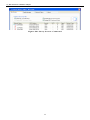
Table of Contents
CHAPTER 1 INTRODUCTION ....................................................................................... 1
Package Contents .................................................................................................. 1
LEDs ........................................................................................................................ 1
Operation ................................................................................................................ 1
CHAPTER 2 INITIAL INSTALLATION ........................................................................... 2
Requirements ......................................................................................................... 2
Procedure ............................................................................................................... 2
CHAPTER 3 USING THE WINDOWS UTILITY ............................................................. 8
Overview ................................................................................................................. 8
System Tray Icon ................................................................................................... 8
Auto Connect ......................................................................................................... 9
Site Survey Screen ................................................................................................ 9
Profile Manager Screen ....................................................................................... 12
Network Status Screen ........................................................................................ 18
About Screen ........................................................................................................ 20
APPENDIX A SPECIFICATIONS ................................................................................. 21
Wireless Adapter .................................................................................................. 21
APPENDIX B ABOUT WIRELESS LANS .................................................................... 22
Modes.................................................................................................................... 22
BSS/ESS ............................................................................................................... 22
Channels ............................................................................................................... 23
WEP & WPA-PSK ................................................................................................. 23
Wireless LAN Configuration ............................................................................... 23
N_Max Wireless CardBus Adapter
Chapter 1
Introduction
This Chapter provides an overview of the Wireless Adapter's features
and capabilities.
Congratulations on the purchase of your new Wireless Adapter. The Wireless Adapter
provides a wireless network interface for your Notebook or PC.
Package Contents
The following items should be included:
Level One WPC-0601 Wireless CardBus Adapter
Quick Installation Guide
CD Manual/Driver/Utility
If any of the above items are damaged or missing, please contact your dealer immediately.
LEDs
Wireless Adapter
The Wireless Adapter has Power and Link/Act LED.
Link LED
Act LED
Blinking - The Adapter's wireless networking is enabled.
Off - The Adapter's wireless networking is disabled.
Slow Blinking- The Adapter has an active connection.
Fast Blinking - Data is being transferred.
Off - The Adapter has not an active connection.
Operation
You should install the supplied software on the CD-ROM before inserting the
Wireless adapter.
1
N_Max Wireless CardBus Adapter
Chapter 2
Initial Installation
This Chapter covers the software installation of the Wireless Adapter.
Requirements
Windows 2000/XP/Vista
CardBus Card Slot
CD-ROM Drive
IEEE802.11n, IEEE802.11b or IEEE802.11g Wireless LAN.
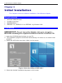
Procedure
IMPORTANT: Do not insert the Adapter into your computer
BEFORE installing the supplied software from the LevelOne CD.
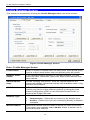
1. Insert the CD-ROM into the drive on your PC.
2. The installation program should start automatically. If it does not, run autorun.exe
program.
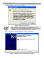
3. Select the WPC-0601 and click “Utility” on the screen.
Figure: Select the Utility of WPC-0601
4. Select the desired installation language on the screen.
2
N_Max Wireless CardBus Adapter
Figure: Select language
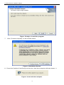
5. On the screen below, click "Next" to start the installation.
Figure: Start Installation
6. Ready to install the program, click "Install" to begin the installation.
3
N_Max Wireless CardBus Adapter
Figure: Ready to install the program
7. Click "Continue Anyway" on the screen below.
Figure: Installation Screen
8. Press the Cardbus Card firmly into the slot then the computer will auto detect it.
Figure: Insert wireless adapter
4
N_Max Wireless CardBus Adapter
9. The Windows "New Hardware" wizard screen will appears, click “Next”.
10. Select Install the software automatically (Recommended) to allow it to complete the
installation of the Windows driver, and then click Next.
Figure: Install the software automatically
5
N_Max Wireless CardBus Adapter
11. If using Windows XP, you may see a warning screen like the example below. If you
do see this screen, just click "Continue Anyway"
Figure: Windows XP Warning
If the wizard can not Install the driver automatically, please
search for driver in the default location. The driver is located in
C:\Program Files\LevelOne\WPC-0601\Driver\ directory.
12. When the Wizard has finished installing the software, click “Finish”.
Figure: Complete the Found New Hardware Wizard
6
N_Max Wireless CardBus Adapter
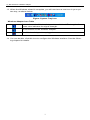
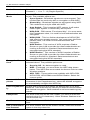
13. When the Windows wizard is complete, you will now have a new icon in your system tray, as shown below.
Figure: System Tray Icon
Wireless Adapter Icon Table
Connection to the Wireless Adapter is established. The length of
green color indicates the signal strength.
No connection to the Wireless Adapter.
The Wireless Adapter is unplugged.
14. You can double- click this icon to configure the Wireless interface. See the following chapter for details.
7
N_Max Wireless CardBus Adapter
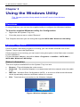
Chapter 3
Using the Windows Utility
This Chapter provides Setup details for the AP mode of the Wireless
Adapter.
Overview
If using Windows, you can use the supplied utility to configure the Wireless interface.
To Use the supplied Windows utility for Configuration
Right-click the System Tray icon
From the pop-up menu, select "Restore".
This Chapter assumes you are using the supplied WPC-0601 Wireless LAN Utility.
System Tray Icon
If the Wireless LAN Utility program is running, you can double-click the icon in the
System Tray to open the application.
If the program is not running, you can start it using the option in the Start menu created
by the installation.
For the Wireless Adapter, this will be Start - Programs - LevelOne – WPC-0601 –
WPC-0601 Wireless LAN Utility.
Status Information
The menu options available from the System Tray icon are:
Restore - This will display the main screen.
Radio Off - The wireless adapter is not associated with the network when the radio
is off.
WZC On - Wireless Zero Configuration (WZC), is a service of Microsoft Windows
which dynamically selects a wireless network to connect.
Exit - Terminate the connection to the Wireless Adapter.
Figure: Wireless Adapter menu
8
N_Max Wireless CardBus Adapter
Connecting to a Wireless Network
Double-click the Icon to open the Site Survey screen, when you can select the Wireless
network you wish to join.
Auto Connect
Normally, this option should be enabled. The adapter will then connect to an available
network which was connected successfully last time.
There are various methods to specify the required network.
On the Profile Manager tab, select the desired profile in the list, and click the Apply
Profile button.
On the Site Survey tab, either double-clicks the network in the list, or selects the
network and click the Connect button.
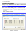
Site Survey Screen
This screen is displayed when you double-click the system tray icon. You can also click
the Site Survey Tab in the screen.
Figure: Site Survey Screen
9
N_Max Wireless CardBus Adapter
Data - Site Survey Screen
Display PC To PC
(Ad-Hoc)
Select this check box to display ad-hoc (computer-to-computer)
networks.
Display 802.11b
Access Points
Select this check box to display 802.11b (infrastructure) networks.
Display 802.11g
Access Points
Select this check box to display 802.11g (infrastructure) networks.
Network Name
Available wireless networks are listed.
MAC Address
This is the MAC address of the Access Point (or Wireless station, if the network is an Ad-hoc network).
Security
Data encryption and authentication methods used on the wireless network
WPS
This will indicate "Y" (the Access Point with WPS function), "Y+".
(the WPS function of the Access Point is in used) or "---" (the
Access Point without WPS function)
CH.
The channel used by the Wireless network.
Signal
This is displayed as percentage (0 ~ 100%).
Frequency
The Wireless band used by this Wireless network.
Network Type
This will indicate "Infrastructure" (displayed device is an Access
Point) or "Ad-hoc". (displayed device is a Wireless station)
Status
The area to the left of the "Rescan" button shows the current
status. In the example above, it shows "Connected".
Rescan
Click this button to rescan for all Wireless networks.
Wireless Network Sequence (order)
You can click the headings (ex. Network Name, MAC Address, Security…) of the
Wireless network table to arrange the Wireless network in the desired order.
To Connect to a Wireless Network
Double-click on the desired network.
Click the name of the wireless network to which you want to connect, and then click
Connect.
Note that once you are connected to a Wireless network, the Site Survey screen will
identify the current wireless network with a blue icon, as shown below.
10
N_Max Wireless CardBus Adapter
Figure: Site Survey Screen - Connected
11
N_Max Wireless CardBus Adapter
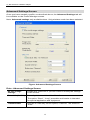
Profile Manager Screen
This screen is accessed by clicking the Profile Manager tab on the main screen.
Figure: Profile Manager Screen
Data - Profile Manager Screen
Profile Name
Enter or select a suitable name for this profile. Each profile must
have a unique name before user can actually save the profile.
Network Name
(SSID)
If the desired wireless network is currently available, you can
select its SSID. Otherwise, type in the SSID of the desired wireless network.
Advanced Settings
On the resulting sub-screen, enter the required data for the
advanced settings. Advanced settings only available under 11b/g
wireless environment.
WPS Function
WPS (Wi-Fi Protected Setup) can simplify the process of connecting any device to the wireless network by using the push
button configuration (PBC) on the Wireless Access Point, or
entering an 8-digit PIN code.
Network Type
Select the desired option:
Wireless Mode
Infrastructure - Select this to connect to an Access point.
Ad-Hoc - Select this if you are connecting directly to another
computer.
Select the desired wireless mode to which you want to connect.
This option only available under Ad-Hoc mode, it allows user to
select the prefer channel.
12
N_Max Wireless CardBus Adapter
Prefer Channel
Select the channel you would like to use under Ad-Hoc mode.
Channel 1 ~ 11 or 1 ~ 13 (Region Specific)
Authentication
Mode
You MUST select the option to match the Wireless LAN you wish
to join. The available options are:
Encryption Method
Open System - Broadcast signals are not encrypted. This
method can be used only with no encryption or with WEP.
Shared Key - Broadcast signals are encrypted using WEP.
This method can only be used with WEP.
Auto Switch - This is another WEP system; it will select
either Open System or Shared Key as required.
WPA-PSK - PSK means "Pre-shared Key". You must enter
this Passphrase value; it is used for both authentication and
encryption.
WPA2-PSK - This is a further development of WPA-PSK,
and offers even greater security. You must enter this Passphrase value; it is used for both authentication and
encryption.
WPA Radius - This version of WPA requires a Radius
Server on your LAN to provide the client authentication according to the 802.1x standard. Data transmissions are
encrypted using the WPA standard.
WPA2 Radius - This version of WPA2 requires a Radius
Server on your LAN to provide the client authentication according to the 802.1x standard. Data transmissions are
encrypted using the WPA2 standard.
The available options depend on the Authentication method
selected above. The possible options are:
Security Off - No data encryption is used.
WEP - If selected, you must enter the WEP data shown
below. This WEP data must match the Access Point or other
Wireless stations.
AES, TKIP - These options are available with WPA-PSK,
WPA2-PSK, WPA-Radius and WPA2-Radius. Select the
correct option.
Create with Passphrase
Enable this check box and enter a word or group of printable
characters in the Passphrase box, select the desired encryption
to automatically configure the WEP Key.
Enter Key Manually
Enable this check box and select the desired key in the dropdown list. Then enter the key values you wish to use and select
the desired encryption. Other stations must have matching key
values.
Passphrase
For WPA-PSK and WPA2-PSK modes, you need to enter the
desired value (8~63 characters). Other Wireless Stations must
use the same key.
Confirm
For WPA-PSK and WPA2-PSK modes, re-enter the value in this
field.
802.1x Authentication Protocol
For WPA Radius and WPA2 Radius modes, select the desired
option in the drop-down list.
13
N_Max Wireless CardBus Adapter
Configure WPA
Radius
For WPA Radius and WPA2 Radius modes, click this button to
open a sub-window where you can enter details of the Radius
Server.
To Add a Profile
1. On the Profile Manager tab, complete the settings on this screen. (Please make
sure to specific the Profile name)
2. Verify that the settings you configured are correct.
3. Click Save Profile.
To Export Profiles
1. On the Profile Manager tab, click Export Profiles. The Save As dialog box appears.
2. Type a name for the profile that you are saving, and then verify that the file name
extension is set to .cfg.
3. Click Save.
To Import Profiles
1. On the Profile Manager tab, click Import Profiles. The open dialog box appears.
2. Select the profile set that you want to import.
3. Click Open.
To Delete a Profile
1. On the Profile Manager tab, select the profile that you want to delete.
2. Click Delete Profile.
To Edit a Profile
1. On the Profile Manager tab, select the profile that you want to edit.
2. Change the profile settings as necessary.
3. Click Save Profile.
To Enable a Profile
1. In the list of available profiles, click the profile that you want to enable.
2. Click Apply Profile.
To Auto-Connect Profiles
1. On the bottom left, tick “Auto-Profile Connect” to enable.
2. The Utility will automatically connect to the latest saved profile.
14
N_Max Wireless CardBus Adapter
Advanced Settings Screen
Once you have created a profile, as described above, the Advanced Settings tab will
be available on the Profile Manager screen.
Note: Advanced settings only available when 11b/g wireless mode has been selected.
Figure: Advanced Settings Screen
Data - Advanced Settings Screen
Do not change
settings
Enable this check box if you don’t want to modify the settings
in this screen.
Preamble (2.4GHz)
Normally, this should be left at "Auto".
The option “Short”, “Long” preamble and header is intended
for special application and equipment.
Transmit Rate
Use this to manually set the speed, if desired. The default is
"Auto".
15
N_Max Wireless CardBus Adapter
Fragment Threshold
The default value is 2346. In some cases, you may be able to
improve performance by adjusting this value.
RTS/CTS Threshold
The default value is 2346. In some cases, you may be able to
improve performance by adjusting this value.
802.11n
Enable 802.11n
Network
802.11n wireless network connectivity
Channel Width
The width of the Channel, either 20Mhz or 40Mhz. The default
value is set as “Auto.”
Guard Interval
This is used to ensure that transmissions do not interfere with
each other. This value is set as "Auto"
Extension Channel
Auto selects the wireless channel. The value is set to “Auto” It
will auto select the most suitable channel.
Antenna Selection
The default value is set to "Auto".
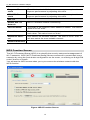
WPS Function Screen
The Wi-Fi Protected Setup (WPS) is to simplify the security setup and management of
Wi-Fi networks. WPS (Wi-Fi Protected Setup) allows consumers to protect their home
networks by using the push button configuration on the router, or entering an 8-digit PIN
code if there's no button.
You will see the WPS screen when you try to connect the wireless network with the
WPS function.
Figure: WPS Function Screen
16
N_Max Wireless CardBus Adapter
Data - WPS Function Screen
Network Name(SSID)
Select the desired wireless network from the drop-down list.
Push the Button on
my access point
Select this and click Start button. Then push the WPS
button of the Access Point.
Enter a PIN into my
access point
Select this to use the PIN method. It will automatically generate the new pin code displayed in the field. Click Start
button and copy the value and paste in the Wi-Fi Protected
Setup screen of the Access Point
Enter the PIN from my
access point
Select this to use the PIN method. Entering the PIN from
your access point in the Wi-Fi Protected Setup screen of the
Access Point and click "Start" button to continue.
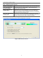
You will see the following screen if WPS configuration is success:
Figure: WPS Success Screen
17
N_Max Wireless CardBus Adapter
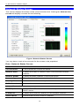
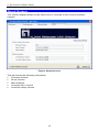
Network Status Screen
This screen displays the status of the current wireless link. Clicking the Network Status tab will display a screen like the following.
Figure: Network Status Screen
You may have to wait a few seconds for the screen to be populated.
Data - Network Status Screen
Link Information
Current Status
It will indicate the current link status.
Network SSID
It shows the SSID or network name of the selected wireless
network.
Network BSSID
It shows the MAC address of the access point.
Network Type
This will indicate "Infrastructure" or "Ad-hoc".
Security Mode
It shows the wireless security that the wireless network is using.
Tx/Rx Speed
It shows the current wireless connection speed.
Internet Protocol
DHCP Option
It shows if the IP address was automatically obtained from a
DHCP server.
IP Address
It shows the current IP address on the wireless interface.
Subnet Mask
Subnet mask for the current IP address.
18
N_Max Wireless CardBus Adapter
Default Gateway
Gateway IP address associated with the current IP address.
DHCP Server
It shows the IP address of the DHCP Server.
Channel Performance
Channel Performance
It graphically presents the Transmission (Tx) rate and Receiving
(Rx) rate over time.
Signal
Signal
It graphically presents the Signal strength.
The Channel Performance diagram indicates the real time TX and RX.
19
N_Max Wireless CardBus Adapter
About Screen
This screen displays details of the traffic sent or received on the current Wireless
network.
Figure: About Screen
This tab shows the following information:
Firmware Version
Driver Version
MAC Address
LevelOne DLL Version
LevelOne Utility Version
20
N_Max Wireless CardBus Adapter
Appendix A
Specifications
Wireless Adapter
Model:
LevelOne WPC-0601 N_Max Wireless CardBus Adapter
Standards:
IEEE 802.11b, IEEE 802.11g, Draft 802.11n compliant
20 MHz BW: 130, 117, 104, 78, 52, 39, 26, 13 Mbps
40 MHz BW: 270, 243, 216, 162, 108, 81, 54, 27 Mbps (802.11n)
Data Rates:
54, 48, 36, 24, 18, 12, 9, and 6 Mbps (802.11g)
11, 5.5, 2, 1 Mbps (802.11b)
Operating Frequency:
2.4 ~ 2.4835 GHz
Modulation Technique:
Draft 802.11n: BPSK, QPSK, 16-QAM, 64-QAM
802.11g: OFDM
802.11b: CCK, QPSK, BPSK
Media Access Protocol:
CSMA/CA
Operating Voltage:
3.3V± 5%
Transmit Power:
Draft 802.11n: 16.5±2 dBm
802.11g: 13.5±2 dBm
802.11b: 16±2 dBm
Security:
WEP 64/128, WPA-PSK, WPA2-PSK, WPA Radius, WPA2
Radius
OS Requirements
Windows XP/2000/Vista
21
N_Max Wireless CardBus Adapter
Appendix B
About Wireless LANs
This Appendix provides some background information about using
Wireless LANs (WLANs).
Modes
Wireless LANs can work in either of two (2) modes:
Ad-hoc
Infrastructure
Ad-hoc Mode
Ad-hoc mode does not require an Access Point or a wired (Ethernet) LAN. Wireless
Stations (e.g. notebook PCs with wireless cards) communicate directly with each
other.
Infrastructure Mode
In Infrastructure Mode, one or more Access Points are used to connect Wireless
Stations (e.g. Notebook PCs with wireless cards) to a wired (Ethernet) LAN. The
Wireless Stations can then access all LAN resources.
Access Points can only function in "Infrastructure" mode, and
can communicate only with Wireless Stations which are set to
"Infrastructure" mode.
BSS/ESS
BSS
A group of Wireless Stations and a single Access Point, all using the same ID (SSID),
form a Basic Service Set (BSS).
Using the same SSID is essential. Devices with different SSIDs are unable to communicate with each other.
ESS
A group of Wireless Stations, and multiple Access Points, all using the same ID
(ESSID), form an Extended Service Set (ESS).
Different Access Points within an ESS can use different Channels. In fact, to reduce
interference, it is recommended that adjacent Access Points SHOULD use different
channels.
As Wireless Stations are physically moved through the area covered by an ESS, they
will automatically change to the Access Point which has the least interference or best
performance. This capability is called Roaming. (Access Points do not have or require
Roaming capabilities.)
22
N_Max Wireless CardBus Adapter
Channels
The Wireless Channel sets the radio frequency used for communication.
Access Points use a fixed Channel. You can select the Channel used. This allows
you to choose a Channel which provides the least interference and best performance. In the USA and Canada, 11 channels are available. If using multiple
Access Points, it is better if adjacent Access Points use different Channels to reduce interference.
In "Infrastructure" mode, Wireless Stations normally scan all Channels, looking for
an Access Point. If more than one Access Point can be used, the one with the
strongest signal is used. (This can only happen within an ESS.)
If using "Ad-hoc" mode (no Access Point), all Wireless stations should be set to
use the same Channel. However, most Wireless stations will still scan all Channels
to see if there is an existing "Ad-hoc" group they can join.
WEP & WPA-PSK
Both WEP and WPA-PSK are standards for encrypting data before it is transmitted.
This is desirable because it is impossible to prevent snoopers from receiving any data
which is transmitted by your Wireless Stations. But if the data is encrypted, then it is
meaningless unless the receiver can decrypt it.
WPA-PSK is a later standard than WEP, and is more secure.
Wireless LAN Configuration
To allow Wireless Stations to use the Access Point, the Wireless Stations and the
Access Point must use the same settings, as follows:
Mode
On client Wireless Stations, the mode must be set to "Infrastructure"
(The Access Point is always in "Infrastructure" mode.)
SSID (ESSID)
Wireless Stations should use the same SSID (ESSID) as the Access
Point they wish to connect to. Alternatively, the SSID can be set to
"any" or null (blank) to allow connection to any Access Point.
Security
The Wireless Stations and the Access Point must use the same
settings for Wireless security (Disabled, WEP, WPA-PSK)
WEP - If WEP is used, the WEP Key must be the same on the Wireless Stations and the Access Point. WEP Authentication ("Open
System" or "Shared Key") must also be the same, unless the Access
Point supports both methods simultaneously.
WPA-PSK - If using WPA-PSK, the PSK (Pre-shared Key) must be
entered on each Wireless station. The encryption key is derived from
the PSK, and changes frequently.
WPA2-PSK - This is a later version of WPA (WPA-PSK). The major
change is the use of AES (Advanced Encryption System) for protecting data. AES is very secure, considered to be unbreakable. The
PSK (Pre-shared Key) must be entered on each Wireless station.
23