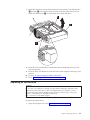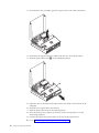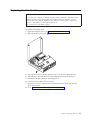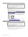
1
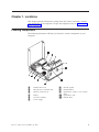
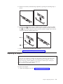
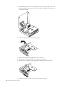
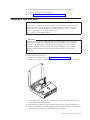
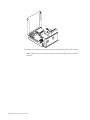
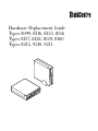
Hardware Replacement Guide
Types 8099, 8116, 8155, 8156
Types 8157, 8158, 8159, 8160
Types 8215, 9210, 9211
Hardware Replacement Guide
Types 8099, 8116, 8155, 8156
Types 8157, 8158, 8159, 8160
Types 8215, 9210, 9211
Third Edition (October 2005)
© Copyright Lenovo 2005.
Portions © Copyright International Business Machines Corporation 2005.
All rights reserved.
U.S. GOVERNMENT USERS – RESTRICTED RIGHTS: Our products and/or services are provided with
RESTRICTED RIGHTS. Use, duplication or disclosure by the Government is subject to the GSA ADP Schedule
contract with Lenovo Group Limited, if any, or the standard terms of this commercial license, or if the agency is
unable to accept this Program under these terms, then we provide this Program under the provisions set forth in
Commercial Computer Software–Restricted Rights at FAR 52.227-19, when applicable, or under Rights in
Data-General, FAR 52.227.14 (Alternate III).
Contents
Overview . . . . . . . . . . . . . . v
Safety information for replacing CRUs . . . . . . v
Safety information for replacing FRUs . . . . . . v
Additional information resources . . . . . . . v
Tools required . . . . . . . . . . . . . vi
Handling static-sensitive devices . . . . . . . vi
Chapter 1. Locations . . . . . . . . . 1
Locating components . . . . . . . . . . .
Locating controls and connectors on the front of your
computer . . . . . . . . . . . . . . .
Locating connectors on the rear of your computer . .
Identifying parts on the system board . . . . . .
1
2
3
4
Chapter 2. Replacing hardware . . . . . 5
Opening the cover . . . .
Replacing the power supply .
.
.
.
.
.
.
© Lenovo 2005. Portions © IBM Corp. 2005.
.
.
.
.
.
.
.
.
. 5
. 6
Replacing the system board assembly . . .
Replacing the microprocessor . . . . .
Replacing a memory module . . . . .
Replacing an adapter . . . . . . . .
Replacing a hard disk drive . . . . . .
Replacing an optical drive . . . . . .
Replacing the diskette drive . . . . . .
Replacing the keyboard . . . . . . .
Replacing the mouse . . . . . . . .
Replacing the internal speaker . . . . .
Completing the CRU replacement . . . .
Updating (flashing) BIOS from a diskette or
CD-ROM . . . . . . . . . . . .
.
.
. 8
12
17
19
21
23
25
26
26
27
28
.
.
.
.
.
.
.
.
.
.
.
.
.
.
.
.
.
.
.
.
.
.
.
.
.
.
.
.
.
.
.
.
. 29
Appendix. Notices . . . . . . . . . . 31
Television output notice .
Trademarks . . . . .
.
.
.
.
.
.
.
.
.
.
.
.
.
.
.
.
. 32
. 32
iii
iv
Hardware Replacement Guide
Overview
This guide is intended to be used by customers who are replacing Customer
Replaceable Units (CRUs) as well as trained service personnel who are replacing
Field Replacement Units (FRUs). In this guide, CRUs and FRUs will often be
referred to as parts.
This guide does not include procedures for all parts. It is expected that cables,
switches, and certain mechanical parts can be replaced by trained service personnel
without the need for step-by-step procedures.
Note: Use only the parts provided by Lenovo™.
This guide contains instructions for replacing the following parts:
v Power supply
v System board
v Microprocessor
v Memory modules
v Adapter
v Hard disk drive
v Optical drive
v Diskette drive
v Keyboard
v Mouse
v Internal speaker
Safety information for replacing CRUs
Do not open your computer or attempt any repair before reading the “Important
safety information” in the Quick Reference that was included with your computer. If
you no longer have this copy of the Quick Reference, you can obtain one online
from the Support Web site at http://www.lenovo.com/think/support.
Safety information for replacing FRUs
Do not attempt any repair before reading the “Important safety information” in the
Hardware Maintenance Manual (HMM) for the computer. You can find the HMM on
the Support Web site at http://www.lenovo.com/think/support.
Additional information resources
If you have Internet access, the most up-to-date information for your computer is
available from the World Wide Web.
You can find the following information:
v CRU removal and installation information
v Publications
v Troubleshooting information
v Parts information
© Lenovo 2005. Portions © IBM Corp. 2005.
v
v Downloads and drivers
v Links to other useful sources of information
v Support phone list
To access this information, point your browser to:
http://www.lenovo.com/think/support
Tools required
To replace some parts in your computer, you might need a flat-blade or Phillips
screwdriver. Additional tools might be needed for certain parts.
Handling static-sensitive devices
Static electricity, although harmless to you, can seriously damage computer
components and parts.
When you are replacing a part, do not open the static-protective package
containing the new part until the defective part has been removed from the
computer and you are ready to install the new part.
When you handle parts and other computer components, take these precautions to
avoid static-electricity damage:
v Limit your movement. Movement can cause static electricity to build up around
you.
v Always handle parts and other computer components carefully. Handle
adapters, memory modules, system boards, and microprocessors by the edges.
Never touch any exposed circuitry.
v Prevent others from touching the parts and other computer components.
v Before you replace a new part, touch the static-protective package containing the
part to a metal expansion-slot cover or other unpainted metal surface on the
computer for at least two seconds. This reduces static electricity in the package
and your body.
v When possible, remove the new part from the static-protective packaging, and
install it directly in the computer without setting the part down. When this is
not possible, place the static-protective package that the part came in on a
smooth, level surface and place the part on it.
v Do not place the part on the computer cover or other metal surface.
vi
Hardware Replacement Guide
Chapter 1. Locations
This chapter provides illustrations to help locate the various connectors, controls,
and components of the computer. To open the computer cover, see “Opening the
cover” on page 5.
Locating components
The following illustration will help you locate the various components in your
computer.
1
2
3
Diskette drive lock
Microprocessor and heat sink
Memory connectors (2)
7
8
9
4
5
6
Battery
PCI riser assembly
Power supply
10
11
© Lenovo 2005. Portions © IBM Corp. 2005.
Internal speaker
Hard disk drive
Optical drive (such as a CD or DVD
drive)
Optical drive lock
Diskette drive
1
Locating controls and connectors on the front of your computer
The following illustration shows locations of the controls and connectors on the
front of your computer.
Note: Not all computer models will have the following controls and connections.
1
2
3
4
2
Hardware Replacement Guide
Optical drive or second hard disk
drive (some models)
Hard disk drive activity indicator
Power-on indicator
Power button
5
USB connectors (2)
6
7
8
Microphone connector
Headphone connector
Diskette drive (some models)
Locating connectors on the rear of your computer
The following illustration shows locations of connectors on the rear of your
computer.
1
2
3
4
5
6
7
8
Power cord connector
Cable lock (Kensington) latch
PCI Express (x1) adapter
connector
PCI adapter connector
Serial connectors (2)
Ethernet connector
USB connectors (2)
VGA monitor connector
9
10
11
Parallel connector
Audio line-in connector
Audio line-out connector
12
13
14
15
USB connectors (4)
Standard keyboard connector
Standard mouse connector
Power supply diagnostic LEDs
Chapter 1. Locations
3
Identifying parts on the system board
The following illustration shows the locations of parts on the system board.
1
2
3
4
5
6
7
8
4
Hardware Replacement Guide
Memory connector 1
Memory connector 2
SATA IDE connectors (2)
Chassis intrusion switch
PCI riser connector
Battery
Clear CMOS/Recovery jumper
Internal speaker connector
9
10
11
12
13
14
15
16
Diskette drive connector
Front panel connector
Power supply connector
PATA primary IDE connector
12V Power connector
Microprocessor
Fan connector 2
Fan connector 1
Chapter 2. Replacing hardware
Attention
Do not open your computer or attempt any repair before reading the “Important safety
information” in the Quick Reference that was included with your computer or in the
Hardware Maintenance Manual (HMM) for the computer. To obtain copies of the Quick
Reference or the HMM, go to the Support Web site at
http://www.lenovo.com/think/support.
Note: Use only parts provided by Lenovo.
Opening the cover
Important
Turn off the computer and wait 3 to 5 minutes to let the computer cool
before opening the computer cover.
To open the computer cover:
1. Remove any media (diskettes, CDs, or tapes) from the drives, shut down your
operating system, turn off all attached devices and the computer.
2. Unplug all power cords from electrical outlets.
3. Disconnect the cables attached to the computer. This includes power cords,
input/output (I/O) cables, and any other cables that are connected to the
computer. See “Locating controls and connectors on the front of your
computer” on page 2 and “Locating connectors on the rear of your computer”
on page 3.
4. Remove the floor stand, if attached.
5. Remove any locking devices, such as a Kensington lock, that secure the
computer cover.
6. Press inward on the two buttons and pivot the top cover upward.
© Lenovo 2005. Portions © IBM Corp. 2005.
5
Replacing the power supply
Attention
Do not open your computer or attempt any repair before reading the “Important safety
information” in the Quick Reference that was included with your computer or in the
Hardware Maintenance Manual (HMM) for the computer. To obtain copies of the Quick
Reference or the HMM, go to the Support Web site at
http://www.lenovo.com/think/support.
To replace the power supply:
1. Remove the screws at the rear of the chassis that secure the power supply.
2. Open the computer cover. See the “Opening the cover” on page 5.
3. Pivot the drive bay assembly upward to gain access to the cable connections.
4. Locate the power supply. See “Locating components” on page 1.
Important
Note the cable routing. It is important to route the cables the same way
after you install the new power supply assembly.
6
Hardware Replacement Guide
5. Disconnect the power supply cables from the hard disk drive and optical
drive.
6. Disconnect the power supply cables 1and 2 from the system board
connectors and from all drives.
7. Remove the power supply cables from the cable clips and ties.
8. Slide the power supply forward and remove from the computer.
9. Install the new power supply into the chassis so that the screw holes in the
power supply assembly align with those in the chassis.
10.
11.
12.
13.
Note: Use only the screws provided by Lenovo.
Install and tighten the assembly screws into the rear of the chassis.
Reconnect the power supply connectors to the hard disk drive and optical
drive.
Reconnect the power supply cables to the system board.
Go to “Completing the CRU replacement” on page 28.
Chapter 2. Replacing hardware
7
Replacing the system board assembly
Attention
Do not open your computer or attempt any repair before reading the “Important safety
information” in the Quick Reference that was included with your computer or in the
Hardware Maintenance Manual (HMM) for the computer. To obtain copies of the Quick
Reference or the HMM, go to the Support Web site at
http://www.lenovo.com/think/support.
To replace the system board assembly:
1. Turn off the computer and allow the computer to cool for one hour.
2. Open the computer cover. See “Opening the cover” on page 5.
3. Pivot the drive bay assembly upward to gain access to the system board.
8
Hardware Replacement Guide
4. While holding the rear of the computer chassis down, pull upward on the
handle provided to remove the PCI riser assembly and any adapters that are
currently installed.
5. Disconnect the cables connected to the system board. See “Identifying parts on
the system board” on page 4.
Important
Note the cable routing. It is important to route the cables the same way
after you install the new system board.
6. Using the two blue handles provided, lift the system board assembly out of
the computer.
Chapter 2. Replacing hardware
9
Note: You will have to tilt the system board assembly and move it around the
edge of the power supply assembly to remove it from the computer.
7. Place the defective system board next to the new system board on a clean, flat
surface.
8. Release the lever 1holding the microprocessor heat sink.
9. Remove the heat sink from the system board.
10. Release the lever 1 for the microprocessor retainer 2 securing the
microprocessor 3 and pivot the retainer upward to the open position.
* XXXXXXXXX*
10
Hardware Replacement Guide
11. Use the vacuum pen 1 to lift the microprocessor straight up and out of the
socket.
Important
Do not touch the gold contacts on the bottom of the microprocessor. Use
the vacuum pen provided to remove and install the microprocessor. If
you must touch the microprocessor, touch only the sides.
*
X
X
X
X
X
X
X
X
X
*
a. Note the orientation of the notches 1 on the microprocessor. This is
important when installing the microprocessor on the new system board.
b. Do not drop anything on the socket while it is open. Keep all contacts as
clean as possible.
12. On the new system board, release the lever securing the microprocessor
retainer and then pivot the retainer until it is fully open.
13. Position the microprocessor so that the notches on the microprocessor are
aligned with the tabs in the microprocessor socket on the new system board.
Important
To avoid damaging the microprocessor, do not tilt the microprocessor
when installing it into the microprocessor socket.
Chapter 2. Replacing hardware
11
14. Use the vacuum pen 1 to lower the microprocessor straight down into the
microprocessor socket.
15. Lower the microprocessor retainer and secure it with the lever.
16.
17.
18.
19.
20.
21.
Note: There will be a black plastic cover on the microprocessor retainer to
protect the socket on the new system board. When you lock the
microprocessor in position, remove the black plastic cover. Place the black
plastic cover on the microprocessor retainer of the defective system board.
Install and secure the heat sink on the microprocessor.
Remove the memory modules from the defective system board, and install
them on the new system board. See to “Replacing a memory module” on page
17. Return here after installing the memory modules and continue to the next
step.
Install the new system board assembly into the computer chassis by aligning
the tabs on the rear of the system board with the slots in the rear of the
computer chassis. Slide the system board toward the rear of the chassis.
Reconnect the cables that were disconnected from the system board. Make
sure all cables are routed correctly. See “Identifying parts on the system
board” on page 4.
Reinstall the PCI riser assembly and adapters.
Go to “Completing the CRU replacement” on page 28.
Replacing the microprocessor
Attention
Do not open your computer or attempt any repair before reading the “Important safety
information” in the Quick Reference that was included with your computer or in the
Hardware Maintenance Manual (HMM) for the computer. To obtain copies of the Quick
Reference or the HMM, go to the Support Web site at
http://www.lenovo.com/think/support.
This section provides instructions on how to replace the microprocessor.
Important
Turn off your computer for at least one hour before removing the
microprocessor to allow the thermal interface between the microprocessor and
the heat sink time to cool down.
12
Hardware Replacement Guide
Important
When you receive a new microprocessor, you will also receive a new heat
sink and vacuum pen. You must use the new heat sink with the new
microprocessor. If you use the old heat sink with the new microprocessor,
your computer might overheat causing intermittent problems.
Important
Do not touch the gold contacts on the bottom of the microprocessor. Use the
vacuum pen provided to remove and install the microprocessor. If you must
touch the microprocessor, touch only the sides.
To replace the microprocessor:
1. Open the computer cover. See “Opening the cover” on page 5.
2. Pivot the drive bay assembly upward to gain access to the microprocessor.
Chapter 2. Replacing hardware
13
3. Release the lever 1 holding the microprocessor heat sink.
4. Remove the heat sink from the system board.
Important
Do not use the old heat sink with the a new microprocessor. If you use
the old heat sink with the new microprocessor, your computer might
overheat causing intermittent problems.
5. Release the lever 1 for the microprocessor retainer 2 securing the
microprocessor3 and pivot the retainer upward until it is fully open.
* XXXXXXXXX*
14
Hardware Replacement Guide
6. Use the vacuum pen 1 to lift the microprocessor straight up and out of the
socket.
Important
Do not touch the gold contacts on the bottom of the microprocessor. If
you must touch the microprocessor, touch only the sides.
*
X
X
X
X
X
X
X
X
X
*
a. Note the orientation of the notches 1 on the microprocessor. This is
important when reinstalling the microprocessor on the system board.
b. Do not drop anything on the socket while it is open. Keep all contacts as
clean as possible.
7. Make sure that the lever on the microprocessor retainer is fully open.
Chapter 2. Replacing hardware
15
*
X
X
X
X
X
X
X
X
X
*
8. Loosen the black cover 3that protect the gold contacts on the new
microprocessor 2, but do not remove the black cover. Use the vacuum pen
1 to pick up the microprocessor, and then completely remove the black
cover.
9. Position the microprocessor so that the notches on the microprocessor are
aligned with the tabs in the microprocessor socket.
Important
To avoid damaging the microprocessor contacts, do not tilt the
microprocessor when installing it into the socket.
10. Use the vacuum pen 1 to lower the microprocessor straight down into the
microprocessor socket.
11. Lower the microprocessor retainer and lower the lever to secure the retainer.
16
Hardware Replacement Guide
12. Place the new heat sink into position and lower the lever 1to secure the heat
sink.
13. Go to “Completing the CRU replacement” on page 28.
Replacing a memory module
Attention
Do not open your computer or attempt any repair before reading the “Important safety
information” in the Quick Reference that was included with your computer or in the
Hardware Maintenance Manual (HMM) for the computer. To obtain copies of the Quick
Reference or the HMM, go to the Support Web site at
http://www.lenovo.com/think/support.
To replace the memory modules:
1. Open the computer cover. See “Opening the cover” on page 5.
Chapter 2. Replacing hardware
17
2. While holding the rear of the computer chassis down, pull upward on the
handle provided to remove the PCI riser assembly and any adapters that are
currently installed.
3. Pivot the drive bay assembly upward to gain access to the memory module.
4. Locate the memory connectors. See “Identifying parts on the system board” on
page 4.
18
Hardware Replacement Guide
5. Remove the memory module being replaced by opening the retaining clips as
shown.
6. Position the replacement memory module over the memory connector. Make
sure the notch 1on the memory module aligns correctly with the connector
key 2 on the system board. Push the memory module straight down into the
connector until the retaining clips close.
7. Reinstall the PCI riser assembly and adapters.
8. Go to “Completing the CRU replacement” on page 28.
Replacing an adapter
Attention
Do not open your computer or attempt any repair before reading the “Important safety
information” in the Quick Reference that was included with your computer or in the
Hardware Maintenance Manual (HMM) for the computer. To obtain copies of the Quick
Reference or the HMM, go to the Support Web site at
http://www.lenovo.com/think/support.
To replace the adapter:
1. Open the computer cover. See “Opening the cover” on page 5.
Chapter 2. Replacing hardware
19
2. While holding the left rear of the computer chassis down, pull upward on the
handle provided to remove the PCI riser assembly including any adapters that
are already installed.
3. Pivot the adapter latch to release the adapter.
4. Remove the adapter being replaced from the PCI riser.
5. Remove the new adapter from its static-protective package.
6. Install the new adapter into the appropriate connector into the PCI riser.
7. Ensure the adapter is fully seated into the adapter connector.
20
Hardware Replacement Guide
8. Pivot the adapter latch to the closed position to secure the adapters.
9. Reinstall the PCI riser and adapters.
10. Go to “Completing the CRU replacement” on page 28.
Replacing a hard disk drive
Attention
Do not open your computer or attempt any repair before reading the “Important safety
information” in the Quick Reference that was included with your computer or in the
Hardware Maintenance Manual (HMM) for the computer. To obtain copies of the Quick
Reference or the HMM, go to the Support Web site at
http://www.lenovo.com/think/support.
Important
When you receive a new hard disk drive, you also receive a set of Product
Recovery CDs. The set of Product Recovery CDs will enable you to restore the
contents of the hard disk to the same state as when your computer was
originally shipped from the factory. For more information on recovering
factory-installed software, refer to “Recovering software” in your Quick
Reference.
To replace the hard disk drive:
1. Open the computer cover. See “Opening the cover” on page 5.
2. Pivot the drive bay assembly upward to gain access to the cable connections.
3. If an optical drive is installed, disconnect the signal cable from the drive to
access the hard disk drive cables.
4. Disconnect the signal and power cables from the rear of the hard disk drive.
5. Pivot the hard disk drive and bracket to the rear, then pull the hard disk drive
out of the hard drive bay by pulling on the blue handle.
Chapter 2. Replacing hardware
21
6. Remove the defective hard disk drive from the bracket by flexing the bracket.
Note: Make sure you notice the orientation of the hard disk drive in the blue
bracket.
22
Hardware Replacement Guide
7. Install the new drive into the blue bracket, flex the bracket, and align the pins
1 through 4on the bracket with the holes in the hard disk drive. Do not
touch the circuit board 5 on the bottom of the hard disk drive.
8. Insert the new hard disk drive and bracket into the hard disk drive bay and
snap into position.
9. Pivot the drive and bracket towards the front of the computer and snap it into
position.
10. Connect the signal and power cables to the drive.
11. Go to “Completing the CRU replacement” on page 28.
Replacing an optical drive
Attention
Do not open your computer or attempt any repair before reading the “Important safety
information” in the Quick Reference that was included with your computer or in the
Hardware Maintenance Manual (HMM) for the computer. To obtain copies of the Quick
Reference or the HMM, go to the Support Web site at
http://www.lenovo.com/think/support.
To replace the optical drive:
1. Open the computer cover. See “Opening the cover” on page 5.
Chapter 2. Replacing hardware
23
2. Pivot the drive bay assembly upward to gain access to the cable connections.
3. Disconnect the signal and power cables from the rear of the optical drive.
4. Slide the optical drive lock 1 to the unlocked position.
5. Open the door at the front of the optical drive and slide it out the front of the
computer.
6. Install the new optical drive into the bay.
7. Slide the optical drive lock to the locked position.
8. Place the master/slave jumper on the drive in the same position as on the
drive being replaced.
9. Connect the signal and power cables to the rear of the optical drive.
10. Go to “Completing the CRU replacement” on page 28.
24
Hardware Replacement Guide
Replacing the diskette drive
Attention
Do not open your computer or attempt any repair before reading the “Important safety
information” in the Quick Reference that was included with your computer or in the
Hardware Maintenance Manual (HMM) for the computer. To obtain copies of the Quick
Reference or the HMM, go to the Support Web site at
http://www.lenovo.com/think/support.
To replace the diskette drive:
1. Open the computer cover. See “Opening the cover” on page 5.
2. Slide the diskette drive lock 1to the unlocked position.
Pivot the drive bay assembly upward to give access to the diskette drive.
Slide the drive towards the rear of the computer and remove the drive.
Disconnect the flat cable from the failing drive.
Connect the flat cable to the new drive.
Install the new drive from the rear of the drive bay assembly and lock the
drive into position.
8. Go to “Completing the CRU replacement” on page 28.
3.
4.
5.
6.
7.
Chapter 2. Replacing hardware
25
Replacing the keyboard
Attention
Do not open your computer or attempt any repair before reading the “Important safety
information” in the Quick Reference that was included with your computer or in the
Hardware Maintenance Manual (HMM) for the computer. To obtain copies of the Quick
Reference or the HMM, go to the Support Web site at
http://www.lenovo.com/think/support.
To replace the keyboard:
1. Remove any media (diskettes, CDs, or tapes) from the drives, shut down your
operating system, and turn off all attached devices and the computer.
2. Unplug all power cords from electrical outlets.
3. Locate the connector for the keyboard. See “Locating connectors on the rear of
your computer” on page 3 and “Locating controls and connectors on the front
of your computer” on page 2.
Note: Your keyboard might be connected to the standard keyboard connector
1 at the rear of the computer or to a USB connector 2 at either the front or
rear of the computer.
4. Disconnect the failing keyboard cable from the computer and connect the new
keyboard cable to the same connector.
5. Go to “Completing the CRU replacement” on page 28.
Replacing the mouse
Attention
Do not open your computer or attempt any repair before reading the “Important safety
information” in the Quick Reference that was included with your computer or in the
Hardware Maintenance Manual (HMM) for the computer. To obtain copies of the Quick
Reference or the HMM, go to the Support Web site at
http://www.lenovo.com/think/support.
To replace the mouse:
1. Remove any media (diskettes, CDs, or tapes) from the drives, shut down your
operating system, and turn off all attached devices and the computer.
2. Unplug all power cords from electrical outlets.
26
Hardware Replacement Guide
3. Locate the connector for the mouse. See “Locating controls and connectors on
the front of your computer” on page 2 and “Locating connectors on the rear of
your computer” on page 3.
Note: Your mouse might be connected to the standard mouse connector 1 at
the rear of the computer or to a USB connector 2 at either the front or rear of
the computer.
4. Disconnect the failing mouse cable from the computer.
5. Connect the new mouse cable to the connector.
6. Go to “Completing the CRU replacement” on page 28.
Replacing the internal speaker
Attention
Do not open your computer or attempt any repair before reading the “Important safety
information” in the Quick Reference that was included with your computer or in the
Hardware Maintenance Manual (HMM) for the computer. To obtain copies of the Quick
Reference or the HMM, go to the Support Web site at
http://www.lenovo.com/think/support.
To replace the internal speaker:
1. Open the computer cover. See “Opening the cover” on page 5.
2. Pivot the drive bay assembly upward to gain access to the speaker.
Chapter 2. Replacing hardware
27
3. Locate the speaker1 See “Locating components” on page 1.
4. Disconnect the speaker cable from the system board. See “Identifying parts on
the system board” on page 4.
Note: Make sure you note the location of the speaker cable when you
disconnect it from the system board.
5. Remove the speaker by sliding it upward and out of the retaining bracket.
Note: You may need to slightly flex the side of the computer to help in
removing the speaker.
6. Install the new speaker.
7. Connect the speaker cable to the system board. See “Identifying parts on the
system board” on page 4.
8. Go to “Completing the CRU replacement.”
Completing the CRU replacement
After replacing the parts, you need to close the cover and reconnect cables,
including telephone lines and power cords. Also, depending on the part that was
replaced, you might need to confirm the updated information in the Setup Utility
program. See ″Starting the Setup Utility″ in your Quick Reference.
To complete the part installation:
1. Ensure that all components have been reassembled correctly and that no tools
or loose screws are left inside your computer. See “Locating components” on
page 1 for the location of various components.
28
Hardware Replacement Guide
2. Make sure that the cables are routed correctly before lowering the drive bay
assembly.
3. Lower the drive bay assembly and position the drive locks to the locked
position. Otherwise, you cannot close the computer cover.
4. Close the computer cover.
5. Re-installed any locking devices, such as a Kensington lock, that secure the
computer cover.
6. If your computer is being placed in the vertical position, attach the floor stand.
7. Reconnect the external cables and power cords to the computer. See “Locating
connectors on the rear of your computer” on page 3.
8. If you are replacing the system board or microprocessor, you must update
(flash) the BIOS. See “Updating (flashing) BIOS from a diskette or CD-ROM.”
9. To update your configuration, see ″Starting the Setup Utility″ in the Quick
Reference.
Note: In most areas of the world, Lenovo requires the return of the defective CRU.
Information about this will come with the CRU or will come a few days after the
CRU arrives.
Updating (flashing) BIOS from a diskette or CD-ROM
Important
Start the Setup Utility program to view your system information. See
“Starting the Setup Utility” in your Quick Reference or the Hardware
Maintenance Manual. If the serial number and the machine type/model listed
on the Main menu do not match what is printed on the label of your
computer, you must update (flash) the BIOS to change the serial number and
the machine type/model.
To update (flash) the BIOS from a diskette or CD-ROM, do the following:
1. Insert a system program update (flash) diskette or CD into the diskette drive or
optical drive. System program updates are available at
http://www.lenovo.com/think/support on the World Wide Web.
2. Turn on the computer. If it is on already, you must turn it off and back on
again. The update begins.
Chapter 2. Replacing hardware
29
3. When you are prompted to select a language, press the number on your
keyboard that corresponds to the language and then press Enter.
4. When prompted to change the serial number, press Y.
5. Type in the seven character serial number of your computer and then press
Enter.
6. When prompted to change the machine type/model, press Y.
7. Type in the seven character machine type/model of your computer and then
press Enter.
8. Follow the instructions on the screen to complete the update.
30
Hardware Replacement Guide
Appendix. Notices
Lenovo may not offer the products, services, or features discussed in this
document in all countries. Consult your local Lenovo representative for
information on the products and services currently available in your area. Any
reference to a Lenovo product, program, or service is not intended to state or
imply that only that Lenovo product, program, or service may be used. Any
functionally equivalent product, program, or service that does not infringe any
Lenovo intellectual property right may be used instead. However, it is the user’s
responsibility to evaluate and verify the operation of any other product, program,
or service.
Lenovo may have patents or pending patent applications covering subject matter
described in this document. The furnishing of this document does not give you
any license to these patents. You can send license inquiries, in writing, to:
Lenovo (United States), Inc.
500 Park Offices Drive, Hwy. 54
Research Triangle Park, NC 27709
U.S.A.
Attention: Lenovo Director of Licensing
LENOVO GROUP LTD. PROVIDES THIS PUBLICATION “AS IS” WITHOUT
WARRANTY OF ANY KIND, EITHER EXPRESS OR IMPLIED, INCLUDING, BUT
NOT LIMITED TO, THE IMPLIED WARRANTIES OF NON-INFRINGEMENT,
MERCHANTABILITY OR FITNESS FOR A PARTICULAR PURPOSE. Some
jurisdictions do not allow disclaimer of express or implied warranties in certain
transactions, therefore, this statement may not apply to you.
This information could include technical inaccuracies or typographical errors.
Changes are periodically made to the information herein; these changes will be
incorporated in new editions of the publication. Lenovo may make improvements
and/or changes in the product(s) and/or the program(s) described in this
publication at any time without notice.
The products described in this document are not intended for use in implantation
or other life support applications where malfunction may result in injury or death
to persons. The information contained in this document does not affect or change
Lenovo product specifications or warranties. Nothing in this document shall
operate as an express or implied license or indemnity under the intellectual
property rights of Lenovo or third parties. All information contained in this
document was obtained in specific environments and is presented as an
illustration. The result obtained in other operating environments may vary.
Lenovo may use or distribute any of the information you supply in any way it
believes appropriate without incurring any obligation to you.
Any references in this publication to non-Lenovo Web sites are provided for
convenience only and do not in any manner serve as an endorsement of those Web
sites. The materials at those Web sites are not part of the materials for this Lenovo
product, and use of those Web sites is at your own risk.
Any performance data contained herein was determined in a controlled
environment. Therefore, the result obtained in other operating environments may
© Lenovo 2005. Portions © IBM Corp. 2005.
31
vary significantly. Some measurements may have been made on development-level
systems and there is no guarantee that these measurements will be the same on
generally available systems. Furthermore, some measurements may have been
estimated through extrapolation. Actual results may vary. Users of this document
should verify the applicable data for their specific environment.
Television output notice
The following notice applies to models that have the factory-installed
television-output feature.
This product incorporates copyright protection technology that is protected by
method claims of certain U.S. patents and other intellectual property rights owned
by Macrovision Corporation and other rights owners. Use of this copyright
protection technology must be authorized by Macrovision Corporation, and is
intended for home and other limited viewing uses only unless otherwise
authorized by Macrovision Corporation. Reverse engineering or disassembly is
prohibited.
Trademarks
The following terms are trademarks of Lenovo in the United States, other
countries, or both:
Lenovo
ThinkCentre
IBM is a trademarks of International Business Machines Corporation in the United
States, other countries, or both.
Other company, product, or service names may be trademarks or service marks of
others.
32
Hardware Replacement Guide
Part Number: 39J8231
Printed in USA
(1P) P/N: 39J8231