1
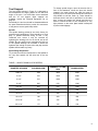
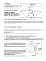
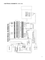
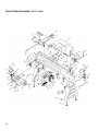
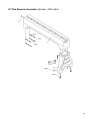
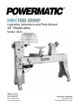
Operating Instructions and Parts Manual
24” Wood Lathe
Model: 4224
WMH Tool Group
2420 Vantage Drive
Elgin, Illinois 60123
Phone: 800-274-6848
www.wmhtoolgroup.com
Part Number: M-0460228
Revision B 11/03
Copyright © WMH Tool Group
This manual has been prepared for the owner and operators of a Powermatic Model 4224 24” Wood Lathe. Its
purpose, aside from machine operation, is to promote safety using accepted operating and maintenance procedures.
To obtain maximum life and efficiency from your wood lathe, and to aid in using the machine safely, read this manual
thoroughly and follow instructions carefully.
Warranty and Service
WMH Tool Group warrants every product it sells. If one of our tools needs service or repair, one of our Authorized
Repair Stations located throughout the United States can provide quick service or information.
In most cases, a WMH Tool Group Repair Station can assist in authorizing repair work, obtaining parts, or perform
routine or major maintenance repair on your Powermatic product.
For the name of an Authorized Repair Station in your area, please call 1-800-274-6848, or visit our web site at
www.wmhtoolgroup.com.
More Information
Remember, the WMH Tool Group is consistently adding new products to the line. For complete, up-to-date product
information, check with your local WMH Tool Group distributor, or visit our web site at www.wmhtoolgroup.com.
WMH Tool Group Warranty
WMH Tool Group makes every effort to assure that its products meet high quality and durability standards and
warrants to the original retail consumer/purchaser of our products that each product be free from defects in materials
and workmanship as follow: 1 YEAR LIMITED WARRANTY ON ALL PRODUCTS UNLESS SPECIFIED
OTHERWISE. This Warranty does not apply to defects due directly or indirectly to misuse, abuse, negligence or
accidents, normal wear-and-tear, repair or alterations outside our facilities, or to a lack of maintenance.
WMH TOOL GROUP LIMITS ALL IMPLIED WARRANTIES TO THE PERIOD SPECIFIED ABOVE, BEGINNING
FROM THE DATE THE PRODUCT WAS PURCHASED AT RETAIL. EXCEPT AS STATED HEREIN, ANY IMPLIED
WARRANTIES OR MERCHANTABILITY AND FITNESS ARE EXCLUDED. SOME STATES DO NOT ALLOW
LIMITATIONS ON HOW LONG THE IMPLIED WARRANTY LASTS, SO THE ABOVE LIMITATION MAY NOT
APPLY TO YOU. IN NO EVENT SHALL THE WMH TOOL GROUP BE LIABLE FOR DEATH, INJURIES TO
PERSONS OR PROPERTY, OR FOR INCIDENTAL, CONTINGENT, SPECIAL, OR CONSEQUENTIAL DAMAGES
ARISING FROM THE USE OF OUR PRODUCTS. SOME STATES DO NOT ALLOW THE EXCLUSION OR
LIMITATION OF INCIDENTAL OR CONSEQUENTIAL DAMAGES, SO THE ABOVE LIMITATION OR EXCLUSION
MAY NOT APPLY TO YOU.
To take advantage of this warranty, the product or part must be returned for examination, postage prepaid, to an
Authorized Repair Station designated by our office. Proof of purchase date and an explanation of the complaint must
accompany the merchandise. If our inspection discloses a defect, we will either repair or replace the product at our
discretion, or refund the purchase price if we cannot readily and quickly provide a repair or replacement. We will
return the repaired product or replacement at WMH Tool Group’s expense, but if it is determined there is no defect,
or that the defect resulted from causes not within the scope of WMH Tool Group’s warranty, then the user must bear
the cost of storing and returning the product. This warranty gives you specific legal rights; you may also have other
rights, which vary from state to state.
WMH Tool Group sells through distributors only. Members of the WMH Tool Group reserve the right to effect at any
time, without prior notice, those alterations to parts, fittings and accessory equipment, which they may deem
necessary for any reason whatsoever.
2
TABLE OF CONTENTS
Safety Rules ...............................................................................................................................................4-5
Safety: Decals ............................................................................................................................................... 6
Specifications ................................................................................................................................................ 7
Receiving ...................................................................................................................................................... 8
Installation ..................................................................................................................................................... 8
Power Connection................................................................................................................................. 8
Inverter Drive System............................................................................................................................ 8
Maintenance.................................................................................................................................................. 8
Adjustments:
Belt Adjustment ..................................................................................................................................... 8
Tool Support.......................................................................................................................................... 8
Spindle .................................................................................................................................................. 9
Speed Range Adjustment ..................................................................................................................... 9
Table 1: Wood Turning Lathe Speeds .......................................................................................................... 9
Tools....... .. .................................................................................................................................................. 10
Operating Instructions ................................................................................................................................. 10
Spindle Turning ........................................................................................................................................... 10
Stock Selection ................................................................................................................................... 11
Mounting Stock ................................................................................................................................... 11
Cutting Techniques ............................................................................................................................. 12
Roughing Out .............................................................................................................................. 12
Beads .......................................................................................................................................... 12
Coves .......................................................................................................................................... 12
"V" Cuts ....................................................................................................................................... 12
Parting Off ................................................................................................................................... 13
Sanding & Finishing .................................................................................................................... 13
Face Plate & Bowl Turning.......................................................................................................................... 13
Mounting Stock ................................................................................................................................... 13
Faceplate or Chuck? ........................................................................................................................... 14
Wood Selection ................................................................................................................................... 14
Checks & Cracks ........................................................................................................................ 14
Distortion ..................................................................................................................................... 14
Tools for Bowl Turning ........................................................................................................................ 14
Bowl Turning Techniques ................................................................................................................... 14
To Shape Outside of Bowl .......................................................................................................... 15
To Shape Interior of Bowl ........................................................................................................... 15
Sanding & Finishing .................................................................................................................... 15
Trouble-Shooting......................................................................................................................................... 16
Electrical Schematic .................................................................................................................................... 17
Parts Lists & Exploded Views:
Stand & Bed Assembly ..................................................................................................................18-20
Headstock Assembly......................................................................................................................21-23
Optional Accessories .......................................................................................................................... 24
Optional Accessory: 65" Bed Extension ........................................................................................24-25
Optional Accessory: Outboard Turning Assembly .........................................................................26-27
3
Warnings
1. Read and understand the entire owner’s manual before attempting assembly or operation.
2. This wood lathe is designed and intended for use by properly trained and experienced personnel only. If you
are not familiar with the proper and safe operation of a wood lathe, do not use it until the proper training and
knowledge have been obtained.
3. Always wear approved safety glasses/face shields while using this machine.
4. Make certain the machine is properly grounded.
5. Before operating the machine, remove tie, rings, watches, other jewelry, and roll sleeves up past the elbows.
Remove all loose clothing and confine long hair. Do not wear gloves.
6. Keep the floor around the machine clean and free of scrap material, oil and grease.
7. Keep machine guards in place at all times when the machine is in use. If removed for maintenance
purposes, use extreme caution and replace the guards immediately.
8. Do not over reach. Maintain a balanced stance at all times, so that you do not fall or lean against blades or
other moving parts.
9. Make all machine adjustments or maintenance with the machine unplugged from the power source.
10. Use the right tool. Do not force a tool or attachment to do a job that it was not designed to do.
11. Replace warning labels if they become obscured or removed.
12. Make certain the switch is in the OFF position before connecting the machine to the power supply.
13. Give your work undivided attention. Looking around, carrying on a conversation and "horse-play" are
careless acts that can result in serious injury.
14. Keep visitors a safe distance from the work area.
15. Use recommended accessories; improper accessories may be hazardous.
16. Read and understand warnings posted on the machine and in this manual. Failure to comply with all of these
warnings may cause serious injury.
17. Some dust created by power sanding, sawing, grinding, drilling and other construction activities contain
chemicals known to cause cancer, birth defects or other reproductive harm. Some examples of these
chemicals are:
• Lead from lead based paint.
• Crystalline silica from bricks, cement and other masonry products.
• Arsenic and chromium from chemically treated lumber.
Your risk of exposure varies, depending on how often you do this type of work. To reduce your exposure to
these chemicals: work in a well ventilated area, and work with approved safety equipment, such as face or
dust masks that are specifically designed to filter out microscopic particles
18. Do not operate this lathe while under the influence of drugs, alcohol or any medication.
19. Keep tools sharp and clean for safe and best performance. Dull tools can grab in the work and be jerked
from the operator`s hands causing serious injury.
20. Check the condition of the stock to be turned. Make sure it is free of knots, warpage, checked ends,
improperly made or cured glue joints and other conditions which can cause it to be thrown out of the lathe.
21. Securely fasten spur/live centers to the material being used.
22. Check centers and center sockets in the headstock and tailstock to be sure they are free of dirt or rust and
oil lightly before inserting centers.
23. Test each set-up by revolving the work by hand to insure it clears the tool rest and bed. Check the setup at
the lowest speed before increasing it to the operating speed.
24. Use the correct cutting tool for the operation to be performed and keep all tools sharp.
25. Use low speeds for roughing and for long or large diameter work. If vibration occurs, stop the machine and
correct the cause. See the speed recommendation chart on the next page.
4
Warnings
SPEED RECOMMENDATIONS
Diameter of Work
Roughing RPM
General Cutting RPM
Finishing RPM
Under 2"
1500
3000
3000
2 to 4"
600
1500
2300
4 to 6"
450
1100
1500
6 to 8"
450
600
1100
8 to 10"
450
600
850
10 to 12"
450
600
850
12 to 14"
450
450
600
26. When sanding, remove the tool rest from the machine, apply light pressure and use a slow speed to avoid
heat build up.
27. When turning large diameter pieces, such as bowls, always operate the lathe at low speeds. See the speed
recommendation chart.
28. Do not attempt to engage the spindle lock pin until the spindle has stopped. If leaving the machine area, turn
it off and wait until the spindle stops before departing.
29. Make no adjustments except speed changes with the spindle rotating and always disconnect the machine
from the power source when performing maintenance to avoid accidental starting or electrical shock.
30. Provide for adequate space surrounding work area and non-glare, overhead lighting.
31. When stopping the lathe, never grab the part or faceplate to slow it down. Let the work coast to a stop.
32. Use only Powermatic factory authorized replacement parts and accessories; otherwise, the warranty and
guarantee are null and void.
33. Do not use this Powermatic wood lathe for other than its intended purpose. If used for other purposes,
Powermatic disclaims any real or implied warranty and holds itself harmless from any injury that may result
from that use.
Familiarize yourself with the following safety notices used in this manual:
! CAUTION: (This means that if precautions are not heeded, it may result in minor or moderate injury
and/or possible machine damage)
!
WARNING: (This means that if precautions are not heeded, it could result in serious injury or
possibly even death).
5
! SAFETY: DECALS
Familiarize yourself with the location and content of this decal on your machine.
6294773
6
SPECIFICATIONS: 4224 Lathe
Distance Between Centers.................................................................................................................................... 42"
Swing Over Bed .................................................................................................................................................... 24"
Spindle Speeds:
Low speed ........................................................................................................................................... 0-910 RPM
Medium speed................................................................................................................................... 0-2000 RPM
High speed ........................................................................................................................................ 0-3500 RPM
Rotation ......................................................................................................................................................FWD/REV
Motor .........................................................................................................................................................3HP, 220V
Lathe Power Requirements...........................................................................................................220V, 3PH or 1PH
Spindle Thread Size .......................................................................................................................... 1-1/4" x 8 T.P.I.
Head/Tailstock Taper .................................................................................................................................. #2 Morse
Height to center of spindle ..............................................................................................................................44-1/2"
Weight .............................................................................................................................................................950 lbs
Tailstock Quill Travel .........................................................................................................................................4-1/2"
3" Faceplate ................................................................................................................................................. standard
14" Toolrest .................................................................................................................................................. standard
Drive System .....................................................................................................................Poly V Belt, Inverter Drive
Spindle Lock................................................................................................................................................. standard
Indexer.......................................................................................................................................................24 position
Knock Out Rod ............................................................................................................................................. standard
Drive Center ................................................................................................................................................. standard
Ball Bearing (live) Center ............................................................................................................................. standard
Hole through tail stock spindle ............................................................................................................................. 3/8"
Hole through head stock spindle.......................................................................................................................... 5/8"
Footprint of stand ................................................................................................................................. 65" L x 24" W
NOTE: The above specifications were current at the time this manual was published, but because of our policy of
continuous improvement, Powermatic reserves the right to change specifications without notice and without incurring
obligations.
7
RECEIVING
Remove the lathe from the shipping container and
check for damage. Report any damage to your
distributor immediately. Accessories are packaged in
a separate carton which will be on the shelf of the
machine stand. Clean protective coating from the bed,
spindles, work rest and face plate with kerosene or a
good commercial solvent. Read the instruction manual
thoroughly for assembly, maintenance, operation and
safety instructions.
INSTALLATION
Install the four leveling screws in the legs, adjust to a
stable position and tighten the jam nuts to lock in
place.
Insert the guard support rod in the guard mounting
bracket at the rear of the headstock. Position a
locking collar on each side of the mounting bracket so
that the lock pin lines up with the holes in the guard
pivot rod, one for guard position and one for load
position. The spring loaded lock pin will hold the
guard in each position.
Power Connection
The lathe will operate on single phase or three phase
230 volt power supply. A three wire pigtail for use on
230 volt single phase power is attached to the inverter
and may be hard wired to the power source or
connected to a receptacle plug. Connect the 230 volt
supply to the black and white leads and ground the
green lead.
If three phase power is used, it will be necessary to
replace the pigtail wire with a 12/4 wire and connect
the three hot leads to the inverter at R, S and T as
shown in the wiring diagram. Always connect the
ground lead.
Before connecting to the power source make sure the
on/off switch is in the off position and turn the speed
dial counterclockwise. If the switch is in the on
position when the power is connected, the inverter will
trip out. If this happens, disconnect power, turn switch
off, wait 30 seconds and then reconnect power.
NOTICE: IF THERE IS A POWER OUTAGE WHILE
OPERATING THE LATHE, TURN THE SWITCH TO
THE OFF POSITION, DISCONNECT POWER
SOURCE, WAIT 30 SECONDS THEN RECONNECT
POWER SOURCE AND RESUME NORMAL
OPERATION.
Inverter Drive System
The model 4224 lathe utilizes the latest technology in
A.C. inverter drives to provide infinitely variable
spindle speeds. The inverter controls the speed of the
motor by varing the frequency of the voltage supplied
to the motor. The inverter provides an acceleration
8
ramp that eliminates the shock of normal across the
line starting. Also a braking feature eliminates long
coasting periods when the lathe is turned off.
The 3 HP motor is specially designed for use with
inverter drives, and is balanced to reduce noise and
minimize vibration.
The A.C. Inverter does not require any programming,
it is pre-programmed from the factory. The buttons
on the face of the inverter should never be pushed
at any time. Use only the controls on the front of the
headstock.
MAINTENANCE
Maintenance on the 4224 lathe should be performed
at periodic intervals to ensure that the machine is in
proper working order, that all fasteners are tight, and
the machine is in adjustment. The more use the
machine is subjected to, the more often it should be
inspected
and
maintained.
Inspection
and
maintenance should be performed at least twice a
year.
WARNING: To prevent accidental starting or
electrical shock, disconnect machine from
! power source before performing any
maintenance.
Periodic cleaning of the lathe is important to keep the
lathe in proper working order. The lathe bed should
be cleaned and oiled periodically so that headstock,
tailstock, and tool support will slide properly. With air
hose periodically blow out headstock to keep saw
dust and chips from collecting on belt and sheaves,
and blow off dust and chips that collect on inverter
(DO NOT DISASSEMBLE INVERTER TO CLEAN).
ADJUSTMENTS
Belt Adjustment
The drive belt sheaves are initally aligned at the
factory, but if any service is performed that affects
their alignment it is very important that they be
realigned. To realign them, loosen the two set screws
on the spindle sheave and slide it in the proper
position. Use of a straight edge along the edge of both
sheaves will simplify the positioning. When properly
aligned, there should be no pulsing sounds or noise
coming from the belt.
Tool Support
The tool support (shown in Figure 5), is designed to
allow adjustment for height, position on the bed, and
angle to the work. Your 4224 lathe comes standard
with the 14" tool support. Other supports are
available; consult the "Optional Equipment" list on
page 24.
Periodically the tool rest should be disassembled and
the parts cleaned and oiled to provide free movement
of the parts to ensure good clamp action.
To change speed ranges, open the access door in
front of the headstock, loosen the pivot lock handle
located in the motor tension slot, raise the motor up
by lifting up on the motor plate handle and relock the
lock handle to hold the motor up. There should be
sufficient slack in the belt to reposition it to the other
step. Loosen the tension lock handle and lower the
motor to tension the belt. Do not overtension; a very
light pressure on the motor plate handle is adequate
to prevent belt slippage.
Spindle
The spindle bearing preload is set at the factory for
general turning applications. There should be no "end
play" of spindle looseness along its axis. If any
looseness ever occurs it may be removed by
tightening the bearing lock nut on the left end of the
spindle. Be very careful not to overtighten the lock nut
or the spindle bearings will overheat. It should be
tightened just enough to remove the end play and the
spindle should rotate very freely.
Speed Range Adjustment
To provide the maximum horsepower to the spindle at
the very slow speeds, set the drive belt in the low
range.
TABLE 1: WOOD TURNING LATHE SPEEDS
DIAMETER OF WORK
ROUGHING RPM
GENERAL CUTTING
RPM
FINISHING RPM
Under 2"
1520
3000
3000
2 to 4"
760
1600
2480
4 to 6"
510
1080
1650
6 to 8"
380
810
1240
8 to 10"
300
650
1000
10 to 12"
255
540
830
12 to 14"
220
460
710
14 to 16"
190
400
620
16" to 20"
175
325
500
20" to 24"
175
260
400
9
TOOLS
If possible, select only quality, high speed steel turning tools. High speed tools hold an edge and last longer than
ordinary carbon steel. As one becomes proficient in turning, a variety of specialty tools for specific applications can
be acquired. The following tools provide the basics for most woodturning projects:
Large Roughing Gouge - 1" to 1-1/4", used to eliminate waste wood.
Skews - 1-1/2" and 1" or 1-1/4", used to make finishing cuts and details.
Spindle Gouges - 1/4", 3/8", 1/2", used to turn beads, coves and other details.
Square Scraper - 1/2", used to create square shoulders.
Large Domed Scraper - 1-1/2", used to reduce ridges on interior of bowls.
Parting Tool - 1/8", used to set diameters for sizing.
Deep Fluted Bowl Gouge - 1/4", 3/8" and 1/2", used for turning bowls & plates.
For safety and best performance, keep tools sharp. If a tool stops cutting or requires excessive pressure to make a
cut, it needs to be sharpened. A number of brand name sharpening jigs and fixtures are available, however, a
woodturner should learn to sharpen tools freehand. For best results, use a slow speed grinder (1800 rpm) fitted with
a 60-grit wheel (for shaping) and a 100-grit wheel (for final sharpening and touchup). The grinder should be located
near your lathe and at a comfortable height. A diamond dresser will keep the wheels true and eliminate glazing.
Never allow the tool to rest in one place on the wheel, keep it moving and use a light touch.
Carbon steel tools can overheat easily and should be cooled frequently. If the edge turns blue, it has lost its temper
and should be ground past the blue area. High-speed steel tools are not as likely to overheat, but can be damaged if
allowed to get red hot. High speed steel tools should not be quenched for cooling. Honing with a diamond lap or
slipstone will save trips to the grinder and keep the edge fresh.
OPERATING INSTRUCTIONS
Before operating the lathe, check each time that everything is in proper working order:
1. Level your machine: use the adjustable levelers to help reduce vibration.
2. Check bearings: adjust only if endplay exists.
3. Check belts: should be snug but not overly tight.
4. Ways - keep clean, use steel wool and wax to prevent buildup of rust and finishes.
5. Toolrest - use mill file to remove nicks and dings.
6. Spindle tapers - should be clean and free of dust and chips for proper seating of tapers. Clean with
scotchbrite or taper cleaner.
7. Tailstock - clean and lubricate ram and locking device.
8. Lighting - proper lighting is essential.
9. Dust extractor - to remove excess sanding dust.
10. Anti-fatigue mat - will help make long hours in front of the lathe more comfortable.
SPINDLE TURNING
Spindle turning takes place between the centers of the lathe. It requires a spur or drive center in the headstock and a
revolving or live center in the tailstock. A cup center rather than a cone center will reduce the risk of splitting the
stock. Figure 2 shows the basic profile shapes in spindle turning.
10
FIGURE 2
STOCK SELECTION
Stock for spindles should be straight grained and free of checks, cracks, knots and other defects. It should be cut
1/8" to 1/4" larger than the finished diameter and may require additional length to remove ends if required. Larger
stock should have the corners removed to produce an octagon making the piece easier to rough down to a cylinder.
1. With a combination square or plastic center finder, locate and mark center on each end of stock. Accuracy is
not critical on full rounds but extremely important on stock where square sections are to remain. Put a dimple in the
stock with an awl or nail, or use a spring-loaded automatic center punch.
2. Extremely hard woods may require kerfs cut into the spur drive end of stock, Figure 3, or may need to have the
spur center driven into the stock with a wood mallet or dead blow hammer, Figure 4. NOTE: Never use a steel face
hammer and never drive stock onto spur while it is mounted in the lathe spindle.
FIGURE 3
FIGURE 4
MOUNTING STOCK
1. Install workpiece by inserting the attached spur center into the spindle taper on the headstock.
2. Bring tailstock into position, lock it to the bed, and advance the spindle with the handwheel in order to seat the
cup center into the workpiece.
3. Move tool support into position. It should be parallel to
the workpiece, just below the centerline and approximately
1/8" to 1/4" from the corners of the workpiece to be turned,
as in Figure 5. Lock tool support to bed.
4. Rotate workpiece by hand to check for proper
clearance.
5. Start lathe at lowest speed and bring it up to the
appropriate RPM for the size of stock used (refer to table on
page 9).
CUTTING TECHNIQUES
11
ROUGHING OUT:
1. Begin with a large roughing gouge. Place the tool on the tool support with the heel of the tool on the surface to
be cut.
2. Slowly and gently raise tool handle until cutting edge comes into contact with the workpiece.
3. Beginning at the tailstock end of the
workpiece, roll the flute (hollowed-out
portion) of the tool in the direction of the
cut, Figure 6. Make long sweeping cuts in a
continuous motion to rough the piece down
to a cylinder. Keep as much of the bevel of
the tool as possible in contact with the
workpiece to ensure control and avoid
catches.
NOTE: Always cut down-hill, or from
large diameter to small diameter. Always
work toward the end of a workpiece,
never start cutting at the end.
4. Once the workpiece is roughed down
to a cylinder, smooth it with a large skew.
Keep the skew handle perpendicular to the
spindle and use only the center third of the
cutting edge for a long smoothing cut
(touching one of the points of the skew to the spinning workpiece may cause a catch and ruin the workpiece).
5. Add details to the workpiece with skew, parting tool, scraper or spindle gouge.
BEADS:
1. Make a parting cut for what is to be a bead to the desired depth. Place the parting tool on the tool support and
move tool forward to make the full bevel of the tool come in contact with the workpiece. Gently raise handle to make
cut to the appropriate depth.
2. Repeat for other side of the bead.
3. Using a small skew or spindle gouge, start in the center between the two cuts and cut down each side to form
the bead. Roll the tool in direction of cut.
COVES:
1. Use a spindle gouge. With the flute of
the tool at 90 degrees to the workpiece,
touch the point of the tool to the workpiece
and roll in towards the bottom of the cove,
Figure 7. Stop at the bottom; attempting
to go up the opposite side may cause
the tool to catch.
2. Move the tool over the desired width
of the cove.
3. With the flute facing the opposite
direction, repeat step 1 for other side of
cove. Stop at bottom of cut.
"V" CUTS:
1. Use the long point of the skew.
(NOTE: Do not press the long point of the skew directly into the workpiece to create the "V"; this will result in a
burned or burnished "V" with fibers being rolled up at both sides.)
2. Lightly mark the center of the "V" with the tip of the skew.
3. Move the point of the skew to the right half of the desired width of your cut.
4. With the bevel parallel to the right side of the cut, raise the handle and push the tool in to the desired depth, as
shown in Figure 8.
5. Repeat from the left side. The two cuts should meet at the bottom and leave a clean "V" cut.
6. Additional cuts may be taken to add to either the depth or width of the cut.
12
PARTING OFF:
1. Use parting tool.
2. Adjust lathe speed to lower RPM for
parting through a workpiece.
3. Place tool on tool support and raise the
handle until it starts to cut and continue to
cut towards the center of the workpiece.
4. Loosely hold on to the piece in one
hand as it separates from the waste wood.
SANDING and FINISHING:
Leaving clean cuts will reduce the amount of
sanding required. Adjust the lathe to a low
speed, and begin with fine sandpaper (120
grit or finer). Coarser sandpaper will leave
deep scratches that are difficult to remove,
and dull crisp details on the spindle.
Progress through each grit without skipping grits (e.g., do not jump from 120 grit to 220 grit). Fold the sandpaper into
a pad; do not wrap sandpaper around your fingers or the workpiece.
To apply a finish, the workpiece can be left on the lathe. Turn off the lathe and use a brush or paper towel to apply
the finish. Remove excess finish before restarting lathe. Allow to dry and sand again with 320 or 400 grit sandpaper.
Apply second coat of finish and buff.
FACE PLATE and BOWL TURNING
Face plate turning is normally done on the inboard side of the headstock over the bed. Larger workpieces must be
turned on the outboard side (remove tailstock and tool support, and move headstock to opposite end of bed).
MOUNTING STOCK
Use of a face plate is the most common method for holding a block of wood for turning bowls and plates:
1. Select stock at least 1/8" to 1/4" larger than each dimension on the finished workpiece.
2. Always select the largest diameter face plate that can be used for the workpiece to be turned.
3. True one surface of the workpiece for mounting against the face plate.
4. Using the face plate as a template, mark the location of the mounting holes, and drill pilot holes of the
appropriate size. Face plates are drilled for No. 12 screws. (Phillips and square drive screws will hold up better than
slotted screws. Sheel metal screws are case hardened with deeper and sharper threads than wood screws.)
If the mounting screws on the face plate interfere with the
workpiece, a glue or waste block can be used.
5. Make a block the same diameter as the face plate, Figure 9.
Both glue block and workpiece should have good flat surfaces for
gluing.
6. Glue the block to the workpiece. Avoid using brown paper or
newspaper between the block and workpiece. It may work fine if
you are using scrapers, but a slight catch with a bowl gouge can
separate the two.
NOTE: When using a glue block, be careful with the
adhesive you select. Dry workpieces can be bonded with ordinary
white or yellow glue but must be clamped to ensure a good bond.
Green workpieces require cyanoacrylate (super glue) or a
urethane adhesive. Urethanes will require clamping.
FACEPLATE OR CHUCK?
While faceplates are the simplest, most reliable method of
holding a block of wood for turning, chucks can also be used. As
13
there are dozens of chucks to choose from, the woodturner should first consider all the different types of turning that
will be done, and read reports or discuss with other turners who own chucks before making a decision. A chuck is
not a requirement but is handy when working on more than one piece at a time. Rather than removing screws, you
simply open the chuck and change workpieces. The most popular ones are four jaw scroll chucks with a variety of
jaws to accomodate different size tenons. Most also come with a screw chuck as well.
WOOD SELECTION
Firewood is the cheapest, most widely available stock to use while learning to turn bowls. Simply waste wood for a
while practicing turning techniques. Develop skill with each tool before attempting to make a finished piece. It is best
to start with dry wood, without worrying about drying or distortion. Once turning becomes comfortable, try green
wood which cuts very easily. As the turner gains experience, he or she will find extraordinary grain and figure in the
form of burls, crotches and bark inclusions.
CHECKS & CRACKS
Green wood will check and crack. For best results, leave logs in as long lengths as you can handle. As the material
starts to dry, surface cracks will develop on the ends of the log. Cut off two to three inches and you should find good,
sound wood. Also cut the log in half along the pith to avoid having it in the finished piece. Most checks radiate from
the pith. As you turn bowls from green wood, make sure you maintain a consistent wall thickness throughout the
piece. Leaving a piece thick in some areas and thin in others will cause the wood to dry unevenly and promote
checks and cracks.
DISTORTION
Distortion is a problem associated with turning green wood. It will vary from one type of wood to the next. Typically,
fruitwoods tend to distort more than others do. It also varies with the time of year the tree was cut and how the logs
are stored.
TOOLS FOR BOWL TURNING
The deep fluted bowl gouge is the most essential and versatile tool for most bowl and faceplate style turning. The
bowl gouge is heavier and easier to control than other types of gouges. It also allows removal of wood much faster
and with less vibration than other gouges. Most average sized bowl work can be accomplished with a 3/8" or 1/2"
bowl gouge. A 1/4" bowl gouge is best suited for smaller bowls and light finishing cuts. Larger 3/4" and 1" bowl
gouges are only used for extremely large pieces.
Large domed scrapers can also be used to help clean up the interior surfaces of bowls. A light touch with the scraper
slightly tilted will eliminate some of the ridges occasionally left by an inexperienced bowl gouge.
BOWL TURNING TECHNIQUES
TO SHAPE the OUTSIDE of the BOWL:
1. Odd shaped burls, crotches and other irregular shaped blanks require special preparation before mounting in a
chuck or onto a faceplate. Remove the bark, if there is any, from what appears to be the center of the top of the
workpiece.
2. Drive spur center into the top of the workpiece with a mallet or dead blow hammer.
3. Slip the spur center into the headstock taper and bring the tailstock with a live or ball bearing center into
position. Lock the tailstock to the bed and advance the spindle in order to seat the cup center into the workpiece.
Tighten the quill lock.
4. Position tool support below the centerline and about 1/4" from the workpiece. (NOTE: For larger outboard
turning, an optional outboard turning stand is used to place the tool support; see your Powermatic dealer).
5. Turn workpiece by hand to ensure proper clearance.
6. Start lathe at lowest speed and bring it up to the maximum safe speed for the size of work to be turned (see
table on page 9). If the machine starts to vibrate, lower the speed until vibration stops.
7. Rough out the outside of the bowl with the 1/2" deep fluted bowl gouge, holding the tool firmly against your hip.
For best control, use your whole body to move the gouge through the workpiece.
8. As bowl takes shape, work on the bottom (tailstock end) to accomodate attaching a face plate.
9. Turn a short tenon (about 1/8" long) the size of the hole in the faceplate, Figure 10. This will allow centering the
workpiece when the faceplate is attached. (NOTE: If you plan to use a chuck, turn a tenon of the appropriate length
and diameter to fit your chuck.)
14
10. Stop the lathe, remove workpiece and
attach face plate or chuck (see "Mounting
Stock" above).
11. Finish turning the outside of bowl with
1/2" or 3/8" bowl gouge. Leave additional
material at base of bowl for support while
turning interior. This will be removed later.
TO SHAPE INTERIOR OF BOWL:
1. Stop lathe and move tailstock away.
Remove center from tailstock to prevent
bumping it with elbow.
2. Adjust tool support in front of the bowl
just below centerline, at a right angle to the
lathe ways.
3. Rotate workpiece by hand to check
clearance.
4. Face off top of bowl by making a light
shearing cut across the top of workpiece, from rim to center.
5. Place 1/2" bowl gouge on toolrest at center of the workpiece with the flute facing top of bowl. The tool handle
should be level and pointed toward four o'clock, as shown in Figure 11.
6. Use left hand to control cutting edge of
gouge, while right hand swings tool handle
around toward your body (see Figure 11).
The flute should start out facing top of
workpiece, and rotate upward as it moves
deeper into the bowl to maintain a clean
even curve.
As tool goes deeper into bowl,
progressively work out toward rim. It may
be necessary to turn the toolrest into the
piece as you get deeper into the bowl.
(NOTE: Try to make one, very light
continuous movement from the rim to the
bottom of the bowl to ensure a clean,
sweeping curve through the piece. Should
there be a few small ridges left, a light cut
with a large domed scraper can even out
the surface.)
7. Develop wall thickness at the rim and maintain it as you work deeper into the bowl (Once the piece is thin
toward the bottom, you cannot make it thinner at the rim). When the interior is finished, move tool support to exterior
to re-define bottom of bowl. (General rule of thumb: the base should be approximately 1/3 the overall diameter of the
bowl).
8. Work the tight area around faceplate or chuck with 1/4" bowl gouge.
9. Begin the separation with a parting tool, but do not cut all the way through yet.
SANDING AND FINISHING:
1. Remove the toolrest and adjust lathe speed to approximately 500 RPM. High speed can build friction while
sanding and cause heat check in some woods.
2. Begin with fine sandpaper (120 grit) and progress through each grit, using only light pressure. Coarser
sandpaper tends to leave deep scratches that are hard to eliminate. Use power-sanding techniques to avoid
concentric sanding marks around your finished piece. Avoid rounding over the rim and foot with sandpaper; try to
keep details crisp. Finish sanding with 220 grit.
3. Remove sanding dust with tack rags or compressed air and, with lathe turned off, apply first coat of finish. Let
stand for several minutes, wipe off excess. Allow to dry before sanding again with 320 or 400 grit sandpaper.
4. Turn lathe back on and continue the separation cut almost all the way through the base. Stop at about 3" and
use a small fine tooth saw to separate the bowl from the waste.
5. Apply second finish coat and allow to dry before buffing.
15
TROUBLE-SHOOTING (4224 Lathe)
PROBLEM
POSSIBLE CAUSE
SOLUTION
Excessive vibration.
1. Defective spindle bearings.
2. Worm or defective belt.
3. Defective motor.
4. Workpiece warped, out-of-round,
has major flaw, or was improperly
prepared for turning.
1. Replace bearings.
2. Replace belt.
3. Replace motor.
4. Correct problem by planing
or sawing, or scrap workpiece.
Motor or spindle stalls.
1. Excessive cut.
2. Defective motor.
3. Excessive belt wear.
4. Improper belt adjustment.
1. Reduce cut depth.
2. Replace motor.
3. Replace belt.
4. Readjust belt.
Motor overheats.
1. Motor overloaded.
1. Correct overload condition,
such as reducing cut depth.
2. Clean sawdust from fan and
duct areas of motor.
2. Improper cooling on motor.
Motor starts slowly or
fails to come up to speed.
1. Low voltage.
2. Defective motor.
Motor fails to develop full
power.
1. Power line overloaded.
2. Undersize wires in supply system.
3. Low voltage.
4. Defective motor.
Tools tend to grab or dig in.
Lathe runs at one speed.
16
1. Dull tools.
2. Tool support set too low.
3. Tool support set too far from workpiece.
1. Request voltage check from
power company and correct
low voltage condition.
2. Replace motor.
1. Correct overload condition.
2. Increase supply wire size.
3. Request voltage check from
power company and correct
low voltage condition.
4. Replace motor.
4. Improper tool being used.
1. Sharpen tools.
2. Reposition tool support height.
3. Reposition tool support closer
to workpiece.
4. Use correct tool for operation.
1. Electronic AC inverter defective, not
programmed properly or loose wiring.
1. Replace electronic AC inverter,
reprogram, or check wiring.
ELECTRICAL SCHEMATIC: 4224 Lathe
17
PARTS LIST: Stand & Bed Assembly (4224 Lathe)
No.
1
2
3
4
5
6
7
8
9
10
11
12
13
14
15
16
17
18
19
20
21
22
23
24
25
28
29
30
31
32
33
34
35
36
37
38
39
40
41
42
43
44
45
46
47
48
49
50
54
55
56
57
58
59
61
63
64
18
Part No.
6294742
6294753
6295851
6295917
4224-105
6294761
6295702
6295703
6294764
6294763
6295919
6295922
TS-0561011
6295709A
6295710
6294773
6295712
6295713
6295714
6295715
6295716
6295717
6294774
6295719
6295902
6295723
6295724
6295725
6295726
6295727
6295728
6295729
6295730
6294770
TS-0650081
6295733
6295734
6295735
6295736
6295737
6295738
6295792
6295740
6295741
6295742
6295743
6295892
6295893
6295749
6295918
6295751
6295848
6295849
6295754
6715013
6295758
6295759
Description
Quantity
Tool Support, 14"........................................................................................................ 1
Tool Support Assembly (Items 3 thru 10, 14, 15, 36, 37)........................................... 1
Tool Support Clamp Bolt (4224)................................................................................. 2
Base Tool Support...................................................................................................... 1
Tailstock Clamp Bolt................................................................................................... 1
Key, 6 x 6 x 45 ............................................................................................................ 1
End Cover................................................................................................................... 1
Socket Head Cap Screw, 10-24 x 5/8"....................................................................... 4
Support Shaft.............................................................................................................. 1
Tool Support Handle................................................................................................... 2
C-Ring......................................................................................................................... 2
Socket Set Screw (Special), 1/4-20 x 1...................................................................... 1
Hex Nut, 1/4-20 .......................................................................................................... 1
Tool Support Rod ....................................................................................................... 1
C-Ring, S-25............................................................................................................... 1
Warning Label ............................................................................................................ 1
Hex Head Screw......................................................................................................... 1
Pin............................................................................................................................... 1
Spring ......................................................................................................................... 1
Washer ....................................................................................................................... 1
Motor Pulley Door....................................................................................................... 1
Knob ........................................................................................................................... 1
Powermatic Label ....................................................................................................... 1
Inverter Box ................................................................................................................ 1
Live Center Assembly................................................................................................. 1
Tailstock Spindle ........................................................................................................ 1
Lead Screw................................................................................................................. 1
Washer ....................................................................................................................... 4
Socket Head Cap Screw ............................................................................................ 2
Nut .............................................................................................................................. 2
Chipbreaker ................................................................................................................ 1
Strain Relief ................................................................................................................ 3
Inverter........................................................................................................................ 1
Clamp ......................................................................................................................... 2
Lock Nut, 3/4-10 ......................................................................................................... 2
Braking Resistor ......................................................................................................... 1
Round Head Screw, 10-24 x 5/16 .............................................................................. 6
Washer, #10 ............................................................................................................... 6
Socket Head Cap Screw, 10-24 x 1/2"....................................................................... 4
Washer, 3/8 ................................................................................................................ 8
Spring Washer 3/8...................................................................................................... 8
Socket Head Screw, 3/8-16 x 1-1/4............................................................................ 8
Hex Nut, 3/8-16 .......................................................................................................... 4
Leveler ........................................................................................................................ 4
Door Lock ................................................................................................................... 1
Stand .......................................................................................................................... 2
Quill Lock Sleeve........................................................................................................ 1
Tailstock Quill Handle................................................................................................. 1
Tailstock...................................................................................................................... 1
Handwheel.................................................................................................................. 1
Handle ........................................................................................................................ 1
Tailstock Handle ......................................................................................................... 1
Tailstock Clamping Shaft (4224) ................................................................................ 1
Tailstock Stud (4224).................................................................................................. 2
Socket Set Screw ....................................................................................................... 1
C-Ring, S-16............................................................................................................... 1
I.D. Label .................................................................................................................... 1
PARTS LIST: Stand & Bed Assembly (4224 Lathe) continued
No.
65
66
67
68
69
70
71
72
73
74
76
77
78
79
80
81
82
83
84
85
86
87
88
89
90
91
92
93
Part No.
6294733
6295760
6295761
6295762
6295763
6295764
6295765
6295766
6295767
6295768
6295769
6295771
6295772
6295773
6295774
6295775
6295776
6295777
6295778
6295779
6295780
6295781
6295782
6295783
6295784
6295903
6295904
6295905
6295906
Description
Quantity
Remote ON/OFF Switch Assembly (Items 65, 66, 68, 70, 71)................................... 1
On/Off Switch.............................................................................................................. 1
Switch Box .................................................................................................................. 1
Bed.............................................................................................................................. 1
Magnet ........................................................................................................................ 1
Power Cord................................................................................................................. 1
Control Cord ............................................................................................................... 1
Strain Relief ................................................................................................................ 1
Signal Cord ................................................................................................................. 1
Hex Socket Screw, 5/16-18 x 1 .................................................................................. 4
Lock Washer, 5/16...................................................................................................... 4
Motor Pulley................................................................................................................ 1
Motor Assembly Plate................................................................................................. 1
Washer, 7/16 .............................................................................................................. 1
Set Screw, 1/4-20 x 3/8 .............................................................................................. 2
Lock Washer, 7/16...................................................................................................... 1
Hex Socket Screw, 7/16-14 x 1-1/4 ............................................................................ 1
Large Washer ............................................................................................................. 1
Stud............................................................................................................................. 1
Handle......................................................................................................................... 1
Spring.......................................................................................................................... 1
Stud............................................................................................................................. 1
Motor Label................................................................................................................. 1
3 HP Motor.................................................................................................................. 1
Motor Cord.................................................................................................................. 1
Live Center Body ........................................................................................................ 1
Live Center Tip ........................................................................................................... 1
Live Center Cap.......................................................................................................... 1
Live Center Rod.......................................................................................................... 1
19
Stand & Bed Assembly (4224 Lathe)
20
PARTS LIST: Headstock Assembly (4224 Lathe)
No.
Part No.
Description
Quantity
1
2
3
4
5
6
7
8
9
10
11
12
13
14
15
16
17
18
19
20
21
22
23
24
25
26
27
28
29
30
31
32
33
34
35
36
37
38
39
40
42
43
44
45
46
47
48
49
50
51
52
53
54
55
56
57
58
6295785
6295786
6295787
6295788
6295789
6295790
6714160
6295792
6295793
6295794
6295795
6295796
6295797
6295798
6295799
6295800
6294725
6295802
6295803
6294736
6295805
6294747
6295807
3064711
6143004
6644005
6295850
6861300
6295915
6294743
6295815
6295816
6295817
6295818
6295819
6295820
6295821
6295822
6295823
6295824
6295826
6295827
6295828
6295829
6860704
6508007
6295832
6295833
6295834
6365012
6708019
6295837
6295838
6295839
6295840
6295841
6295842
Handwheel ................................................................................................................ 1
Nut, Lock ................................................................................................................... 1
Socket Cap Screw, M6 x 25...................................................................................... 1
Bearing, 63208.......................................................................................................... 1
Wave Washer............................................................................................................ 1
Headstock ................................................................................................................. 1
Set Screw, 1/4-20 x 1/4............................................................................................. 2
Socket Cap Screw, 3/8-16 x 1-1/4 ............................................................................ 4
Spring Washer, 3/8 ................................................................................................... 4
Stud ........................................................................................................................... 4
Spindle Pulley ........................................................................................................... 1
Set Screw, 1/4-20 x 38.............................................................................................. 4
Bearing, 6209LB ....................................................................................................... 2
Bushing ..................................................................................................................... 1
Front Plate................................................................................................................. 1
Hex Socket Round Head Screw, 10-24 x 1/2 ......................................................... 13
Spur Center 1", MT2 ................................................................................................. 1
Key, 6 x 6 x 50 .......................................................................................................... 1
Head Spindle............................................................................................................. 1
Face Plate, 3"............................................................................................................ 1
Belt, V-550J............................................................................................................... 1
Guard Assembly........................................................................................................ 1
Bracket ...................................................................................................................... 1
Lathe Guard Bracket................................................................................................. 1
Retaining Collar......................................................................................................... 2
Plunger ...................................................................................................................... 1
Socket Cap Screw, 3/8-16 x 3 .................................................................................. 2
Spring Washer, 3/8 ................................................................................................... 2
Control Pot Assembly................................................................................................ 1
Knockout Rod............................................................................................................ 1
Tap Screw, M3 x 10 .................................................................................................. 4
E-Ring, E-7................................................................................................................ 1
Index Bushing ........................................................................................................... 1
Index Shaft ................................................................................................................ 1
Index Knob ................................................................................................................ 1
Spring ........................................................................................................................ 1
Bolt ............................................................................................................................ 1
Spring ........................................................................................................................ 1
Tap Screw, 1/4 x 1/2 ................................................................................................. 2
Speed Indicator & Sensor Assy. ............................................................................... 1
Fixed Plate ................................................................................................................ 1
Nut............................................................................................................................. 2
Washer ..................................................................................................................... 2
O-Ring ....................................................................................................................... 1
Lock Washer ............................................................................................................. 2
Nut............................................................................................................................. 2
Knob .......................................................................................................................... 1
Door Panel ................................................................................................................ 1
Speed Label .............................................................................................................. 1
Door Hinge ................................................................................................................ 1
Socket Cap Screw, 8-32 x 5/8 .................................................................................. 4
Pad ............................................................................................................................ 1
Round Head Screw, M3 x 20 .................................................................................... 2
Push/Pull Switch ....................................................................................................... 1
Control Panel Knob ................................................................................................... 1
Fwd/Rev Switch ........................................................................................................ 1
Headstock Plate ........................................................................................................ 1
21
PARTS LIST: Headstock Assembly (4224 Lathe) Continued
No.
59
60
61
62
63
22
Part No.
6295843
6295844
6294744
TS-0270011
6295923
Description
Quantity
Clamp........................................................................................................................ 1
Nut, #10-24 ............................................................................................................... 1
Faceplate Spanner.................................................................................................... 1
Socket Set Screw, 5/16-18 x 1/4 .............................................................................. 2
Clamp Washer .......................................................................................................... 1
Headstock Assembly (4224 Lathe)
23
OPTIONAL ACCESSORIES (4224 Lathe)
Part No.
Description
6294730
6294731
6294734
6294739
6294740
6294741
6294745
6294747
6294736
6294737
6294738
6294751
6295845
6295846
Metal Spinning Tool Support, 12"
Tool Support, 26"
Adapter, 1-1/4" to 1-1/2"
Tool Support, 6"
Bowl Turning Tool Support (RH)
Tool Support, 16"
Ball Bearing Center
Guard Assembly
Face Plate, 3"
Face Plate, 4"
Face Plate, 7"
Bowl Turning Tool Support (LH)
Short Outfeed Bed Extension, 20"
Tool Rest Base Assembly, 24"
65" Bed Extension Assembly (Optional - 4224 Lathe)
No.
Part No.
Description
1
2
3
4
5
6
7
8
9
10
11
6295847
6295901
6295861
6295743
6295862
6295859
6295860
6295737
6295738
6295739
6295740
6295741
65" Bed Extension Assembly (Items 1-11) ...................................................................... 1
65" Bed Extension............................................................................................................ 1
Pin .................................................................................................................................... 1
Stand................................................................................................................................ 1
Hex Socket Cap Screw, 5/8-11 x 2.................................................................................. 4
Lock Washer, 5/8 ............................................................................................................. 4
Washer, 5/8...................................................................................................................... 4
Washer, 3/8...................................................................................................................... 4
Lock Washer, 3/8 ............................................................................................................. 4
Hex Socket Cap Screw, 3/8-16 x 1-1/4 ........................................................................... 4
Hex Nut, 3/8-16................................................................................................................ 2
Leveler ............................................................................................................................. 2
24
Quantity
65" Bed Extension Assembly (Optional - 4224 Lathe)
25
PARTS LIST: Outboard Turning Assembly (Optional - 4224 Lathe)
No.
Part No.
Description
1
2
3
4
5
6
7
8
9
10
11
12
13
14
15
16
17
6295858
6295845
6295846
6295852
6295853
6294770
TS-0650081
6295860
6295854
6295855
6295856A
6295710
6295857
6295702
6294761
6294762
6295851A
6294764
6294763
6295703
Outboard Turning Assembly (Items 1 thru 17) ................................................................ 1
Short Outfeed Bed Extension Assembly (Items 1, 5, 6, 7) .............................................. 1
Tool Rest Base Assembly (Items 2, 3, 4, 8 thru 17) ........................................................ 1
20" Bed Extension............................................................................................................ 1
Extension Rod.................................................................................................................. 1
Clamp............................................................................................................................... 1
Lock Nut, 3/4-10............................................................................................................... 1
Washer, 5/8...................................................................................................................... 4
Lock Washer, 5/8 ............................................................................................................. 4
Hex Socket Cap Screw, 5/8-11 x 1-1/2 ........................................................................... 4
Rod................................................................................................................................... 1
C-Ring .............................................................................................................................. 1
Tool Support Base ........................................................................................................... 1
End Cover ........................................................................................................................ 1
Key 6 x 6 x 45 .................................................................................................................. 1
Bushing ............................................................................................................................ 1
Tool Support Clamp Bolt.................................................................................................. 1
Support Bracket ............................................................................................................... 1
Tool Support Handle ........................................................................................................ 4
Hex Socket Cap Screw, 10-24 x 5/8................................................................................ 4
26
Quantity
Outboard Turning Assembly (Optional - 4224 Lathe)
To order parts or reach our service department, please call our toll-free number between 7:00 a.m. and 6:00 p.m.
(CST), Monday through Friday. Having the Model Number and Serial Number of your machine available when you
call will allow us to serve you quickly and accurately. Locating the stock number of the part(s) required from your
parts manual will also expedite your order.
Phone No.: 800-274-6848
Website: www.wmhtoolgroup.com
27
WMH Tool Group
2420 Vantage Drive
Elgin, Illinois 60123
Phone:800-274-6848
www.wmhtoolgroup.com
28