1
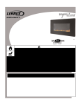
INSTALLATION AND OPERATION INSTRUCTIONS
Catalytic Vent - Free Wall-Mounted
Fireplace
Model: Scandium-NG
P/N 850,055M Rev. NC, 04/2007
Installer: Leave This Manual With The Appliance.
Consumer: Retain This Manual For Future Reference.
In the Commonwealth of Massachusetts:
• Installation must be performed by a licensed plumber or gas fitter
• See Table of Contents for location of additional Commonwealth of
Massachusetts requirements
ScandiumTM
Report No. :
317-S-05-5
WARNINGS
• Hot! Do not touch! This appliance will be hot during operation and will retain heat for a while after shutting
off the appliance. Severe burns may result.
• Carefully supervise children in the same room as appliance.
• Due to high temperatures, the appliance should be located out of traffic and away from furniture or draperies.
Do not place clothing or other materials on or near this appliance.
• Improper installation, adjustment, alteration, service or maintenance can cause injury or property damage. Refer to this
manual. For assistance or additional information consult a qualified installer, service agency or the gas supplier.
• Do not build a wood fire. Do not burn wood or other material in these appliances.
• This is an unvented gas-fired heater. It uses air (oxygen) from the room in which it is installed. Provisions for adequate
combustion and ventilation air must be provided. Refer to Combustion and Ventilation Air Section.
• This appliance may be installed in an aftermarket, permanently located, manufactured (mobile) home, where not prohibited
by local codes.
• The appliance is only for use with the type of gas indicated on the rating plate. This appliance is not convertible for use
with other gases.
WARNING: If the information in this manual is not followed exactly, a fire or explosion may result causing property
damage, personal injury or loss of life.
FOR YOUR SAFETY
Do not store or use gasoline or other flammable vapors or liquids in the vicinity of this or any other appliance.
WHAT TO DO IF YOU SMELL GAS:
• DO NOT light any appliance.
• DO NOT touch any electrical switches.
• Do not use any phone in your building.
• Immediately call your gas supplier from a neighbor’s phone. Follow your gas supplier's instructions.
• If your gas supplier cannot be reached, call the fire department.
Installation and service must be performed by a qualified installer, service agency or the gas supplier.
TABLE OF CONTENTS
Section
1.0
2.0
3.0
4.0
5.0
6.0
7.0
8.0
9.0
10.0
11.0
12.0
13.0
14.0
15.0
16.0
17.0
18.0
19.0
20.0
21.0
22.0
23.0
24.0
25.0
26.0
27.0
28.0
29.0
2.0 PACKAGING LIST
Contents
Page No.
General Information
2
Packaging List
2
Appliance Data
2
Important Safety Information
2
Codes
4
Combustion and Ventilation Air
4
Site Requirements
4
Preparing the Appliance
5
Mounting the Appliance
5
Checking the Burner
6
Connecting a Gas Line
6
Checking the Gas Connections
7
Gas Pressure Check
7
Spark Gap
7
Assembly of the Glass Facia
7
Fitting the Glass Facia
8
Fitting the side panels
8
Briefing the customer
9
Servicing
9
Servicing the Burner
9
Pilot Assembly
10
Catalysts
10
Testing for Firebox Leakage
10
Cleaning
10
Lighting Instructions
11
To Turn off gas to Appliance
11
Troubleshooting Guide
12
Replacement Parts
12
Positioning of field assembled parts
13
QUANTITY
1
1
1
1
1
1
DESCRIPTION
Firebox and burner assembly
Installation and operating instructions
Glass facia panel assembly
Fitting template
Screw and wall plug pack
Rubber grommet
3.0 APPLIANCE DATA
Gas Type
Gas inlet pressure Maximum
Minimum
Regulator Pressure Setting
Max Energy Input
Min Energy Input
Pilot Energy Input
Burner (Manifold) Pressure High
Low
Main burner flow restrictor
Oxypilot
Gas Inlet Connection
Ignition
Spark Gap
Natural Gas
10.5” w.c.
6” w.c.
5” w.c.
11,950 BTU/hr
6,820 BTU/hr
560 BTU/hour
2.4” w.c.
0.8” w.c.
2.0mm (0.079”)
SIT/Bray 9082
3/8” NPT at regulator
Piezo spark
1/8” - 3/16”
Please see Data Plate affixed to appliance for current data.
This appliance is for use only with the gas type, and at the pressure
stated on the appliance Data Plate.
1.0 GENERAL INFORMATION
4.0 IMPORTANT SAFETY INFORMATION
This appliance is a high efficiency, unvented, flame effect gas heater. It
provides radiant and convected warmth both efficiently and safely
utilizing the latest type catalytic convertor burner technology. The
appliance does not require a flue system of any type as the catalytic
converter cleans the flue products to provide a complete combustion
system, which is intrinsically safe.
IMPORTANT
READ AND UNDERSTAND THESE INSTRUCTIONS
COMPLETELY BEFORE INSTALLING OR OPERATING
YOUR UNVENTED ROOM HEATER.
These heaters are fitted with a specially designed pilot utilizing an
oxygen depletion sensor (ODS) which responds to the amount of
oxygen available in the room and shuts the heater off before the oxygen
level drops below 18%. The pilot can be relit only when fresh air is
available. Refer to the Combustion and Ventilation Air section.
T H E F O L L O W I N G B O X E D I N F O R M AT I O N A P P L I E S T O
REQUIREMENTS FOR THE COMMONWEALTH OF MASSACHUSETTS.
The appliance is designed to fit various types of situations as listed in
the Installation Requirements.
Unvented Room Heaters shall be installed in accordance with 527 CMR
30.00 and 248 CMR 3.00 through 7.00:
This appliance is factory set for operation on the gas type, and at the
pressure stated on the appliance rating plate.
(a) Permits and Inspections: In addition to complying with 248 CMR 3.05
the following requirements must be satisfied:
On first light up of a new appliance, initial curing of high temperature
paint and burning off of lubricants may occur for the first few hours of
operation. During this period some smoke may be emitted from outlet
grille, this should be no cause for concern. Accordingly, the room
should be well ventilated with all windows and doors open during this
period.
1. A permit shall be obtained from the head of the fire department and the
local or state gas inspector having jurisdiction for the installation of all
unvented propane or natural gas-fired space/room heaters.
Note: The following requirements reference various Massachusetts and
national codes not contained in this document.
2. The permits shall be conditioned upon final inspection and approval of
installation by the head of the fire department and the local or state gas
inspector having jurisdiction.
Read all these instructions before commencing installation. All
instructions must be handed to the user for safekeeping.
3. A copy of the manufacturer’s installation/operating literature shall be
submitted with each permit application.
4. Before operation, the Head of the Fire Department and the local or state
gas inspector shall inspect the installation for compliance with 527 CMR
(Board of Fire Prevention Regulations) and 248 CMR (Board of State
Examiners of Plumbers and Gas Fitters).
2
WARNING
4.0 IMPORTANT SAFETY INFORMATION (continued)
FAILURE TO COMPLY WITH THE INSTALLATION AND
OPERATING INSTRUCTIONS PROVIDED IN THIS
DOCUMENT WILL RESULT IN AN IMPROPERLY INSTALLED
AND OPERATING APPLIANCE, VOIDING ITS WARRANTY.
ANY CHANGE TO THIS APPLIANCE AND/OR ITS
OPERATING CONTROLS IS DANGEROUS. IMPROPER
INSTALLATION OR USE OF THIS APPLIANCE CAN CAUSE
SERIOUS INJURY OR DEATH FROM FIRE, BURNS,
EXPLOSION OR CARBON MONOXIDE POISONING.
T H E F O L L O W I N G B O X E D I N F O R M AT I O N A P P L I E S T O
REQUIREMENTS FOR THE COMMONWEALTH OF MASSACHUSETTS.
5. A final inspection by the state or local gas inspector of the unvented
space/room heater shall not be performed until proof is provided that the
head of the fire department having jurisdiction has granted a permit.
(b) Unvented natural gas-fired space/room heaters shall conform to ANSI
Z21.11.2, be equipped with an oxygen depletion safety (ODS) shutoff
system and be Product-approved in accordance with 248 CMR.
(c) Unvented natural gas-fired space/room heaters shall be installed in
accordance with their listings and the manufacturer’s instructions. Proper
clearances to combustibles shall be maintained. In no case shall the
clearances be such as to interfere with combustion air and accessibility.
• Children and adults should be alerted to the hazard of high surface
temperature and should stay away to avoid burns or clothing ignition.
(d) Installations shall be of a permanent type, with a permanently piped
fuel supply in accordance with 248 CMR. LPG appliances shall be subject
to the storage requirements in accordance with 527 CMR 6.00. Portable
unvented or natural gas-fired space/room heaters shall be prohibited.
• Do not place clothing or other flammable material on or near the
heater.
(e) Unvented natural gas-fired space/room heaters shall be prohibited in
bedrooms and bathrooms.
• Installation and repair should be done by a qualified service person.
The heater should be inspected before use and at least annually by a
professional service person. More frequent cleaning may be required
due to excessive lint from carpeting, bedding material, etc. It is
important that control compartments, burners and circulating air
passageways of the heater be kept clean.
• Young children should be carefully supervised when they are in the
same room with the heater.
• Any safety screen or guard removed for servicing the heater must be
replaced prior to operating the heater.
(f) Space/room heaters shall be properly sized for the room or space of
installation, but shall not exceed a maximum of 40,000 BTU input per room
or space.
(g) In occupancies with an unvented natural gas-fired space/room heater,
no less than one listed carbon monoxide detector that is installed in
accordance with the manufacturers instructions shall be installed and
maintained near the space where the heater is located.
• Allow the heater to cool before servicing. Always shut off the gas to
the heater while performing service work.
1. Any building wherein the heater is to be installed shall, as a precondition
to such installation, have working smoke detectors installed and
maintained in accordance with the requirements of 780 CMR (State Board
of Building Regulations and Standards) in effect at the time of construction
or;
• The heater and its individual shut-off valve must be disconnected
from the gas supply piping system while performing any tests of the
gas supply piping system at pressures in excess of 1/2 psig.
• The installation must conform with local codes or, in the absence of
local codes with the National Fuel Gas Code, ANSI Z223.1.
• The heater must be isolated from the gas supply piping system by
closing its individual manual shut-off valve during any pressure
testing of the gas supply piping system at test pressures equal to or
less than 1/2 psig.
2. If no requirement was in effect at the time of construction the smoke
detector shall be compliant and installed as provided for in M.G.L. c. 148,
§ 26E.
• Keep heater area clear and free from combustible materials, gasoline
and other flammable vapors and liquids.
(h) In rooms and buildings served by an unvented natural gas-fired
space/room heater, a primary source of heat, which is operable, shall be
permanently installed and maintained in the building in accordance with
105 CMR (Department of Public Health).
• Do not use this heater if any part has been under water. Immediately
call a qualified service technician to inspect the room heater and to
replace any part of the control system and any gas control which has
been under water.
(i) Sellers of unvented natural gas-fired space/room heaters shall provide
to each purchaser a copy of 527 CMR 30.00 upon sale of the unit.
• Input ratings are shown in BTU per hour and are for elevations up to
4,500 feet. If these appliances are installed at elevations above 4,500
feet, nuisance pilot outages may occur. Do not install this heater at an
elevation above 4,500 feet if the gas supply has not been derated for
that elevation. Consult your local gas supplier.
• Installation and repair must be done by a plumber or gas fitter licensed
in the Commonwealth of Massachusetts.
•The individual manual shut-off must be a T-handle type valve.
• Ensure that the heater is clean when operating. Excessive dust
accumulation on the burner will increase the amount of carbon
monoxide formation and could lead to carbon monoxide poisoning
and/or death.
New York : This appliance is approved for installation in the U.S. state
of New York, but not New York City.
• Vent-free gas fireplaces are designed for use as a supplemental
heaters. They are not intended for continuous use as a primary
source.
• The flexible gas line connector used shall not exceed 36 inches (92
centimeters) in length.
WARNING
WARNING
FAILURE TO KEEP THE PRIMARY AIR OPENING(S) OF THE
BURNER(S) CLEAN MAY RESULT IN SOOTING AND
PROPERTY DAMAGE.
3
CHECK GAS TYPE : THE GAS SUPPLY MUST BE THE SAME
AS STATED ON THE APPLIANCE’S RATING PLATE. IF THE
GAS SUPPLY IS DIFFERENT DO NOT INSTALL THE
APPLIANCE. CONTACT YOUR DEALER FOR THE CORRECT
MODEL.
Example:
5.0 CODES
Adhere to all local codes or in their absence the latest edition of The
National Fuel Gas Code ANSI Z223.1 or NFPA54 which can be obtained
from The American National Standards Institute, Inc. (1430 Broadway, New
York, NY, 10018) or National Fire Protection Association, Inc. (Batterymarch
Park, Quincy, MA, 02269).
_______ BTU/Hr (actual amount of BTU/Hr used)
Example:
61,440
67,000
6.0 COMBUSTION AND VENTILATION AIR
The National Fuel Gas Code, ANSI Z223.1/NFPA 54 defines a confined
space as a space whose volume is less than 50 ft 3 per 1,000 BTU/Hr (4.8
m3 per kW) of the aggregate input rating of all appliances installed in that
space and an unconfined space as a space whose volume is not less than
50 ft 3 per 1,000 BTU/Hr (4.8 m3 per kW) of the aggregate input rating of all
appliances installed in that space.
b. Vent room directly to the outdoors. Refer to National Fuel Gas Code,
ANSI Z223.1, Section 5.3.
c. Install a lower BTU/Hr heater, to make the area an unconfined space.
If the actual BTU/Hr used is less than the maximum BTU/Hr the space can
support, then the space is an unconfined space. You will need no additional
fresh air ventilation for an unconfined space.
Rooms communicating directly with the space in which the appliances are
installed, through openings not furnished with doors, are considered a part
of the unconfined space.
Unusually tight construction is defined as construction where:
7.0 SITE REQUIREMENTS
a. wall and ceilings exposed to the outside atmosphere have a continuous
water vapor retarder with a rating of one perm or less with openings
gasketed or sealed, and
This appliance is designed to be wall-hung. Do not recess any part of
the appliance into the wall. This appliance may be installed in any
room in a home except bedrooms or bathrooms - or areas where large
amounts of steam are likely to be generated.
b. weather stripping has been added on operable windows and doors, and
c. caulking or sealants are applied to areas such as joints around window
and door frames, between sole plates and floors, between wallceiling joints,
between wall panels, at penetrations for plumbing, electrical, and gas lines,
and at other openings.
Use the following equations to determine if you have a confined or
unconfined space.
It should be noted that heaters create warm air currents. These
currents move heat to wall surfaces next to the heater. Installing
the heater next to vinyl or cloth wall coverings or operating the
heater where impurities in the air (such as tobacco smoke or
candle smoke) exist, may discolour walls.
Determine the volume of space — ft 3.
Installation in living rooms is common, however other rooms such as
kitchens, dining rooms and hallways are permitted, providing a suitable
natural gas supply is available, and rooms sizing and ventilation
requirements are strictly adhered to (see section 4).
Length x Width x Height = _____ ft 3
(Include adjoining rooms with doorless passageways or ventilation
grills between rooms.)
The appliance is designed to be versatile, and as such will operate correctly
when exposed to normal gentle drafts experienced within the home. It is not
recommended, however that the appliance be installed in areas where it is
likely to be exposed to persistent strong drafts, that may be generated by
outside doors or windows, air vents etc. It is recommended that the
appliance should not be installed within 20” of any air vent.
Example: 24' (L) x 16' (W) x 8' (H) = 3072 ft 3
Divide the volume of space by 50 ft 3 to determine the maximum
BTU/Hr the space can support.
______ (volume of space – ft 3)/ 50 ft 3 =
(Maximum BTU/Hr the space can support)
WARNING
Example: 3072 ft 3 / 50 ft 3 = 61.44
or 61,440 BTU/Hr the space can support.
IF THE AREA IN WHICH THE HEATER MAY BE OPERATED IS
SMALLER THAN THAT DEFINED AS AN UNCONFINED
SPACE OR IF THE BUILDING IS OF UNUSUALLY TIGHT
CONSTRUCTION, PROVIDE ADEQUATE COMBUSTION AND
VENTILATION AIR BY ONE OF THE METHODS DESCRIBED
IN THE NATIONAL FUEL GAS CODE, ANSI Z223.1/NFPA 54,
SECTION 5.3 OR APPLICABLE LOCAL CODES.
Add the BTU/Hr of all the fuel burning appliances in the space.
Vent-Free heater
_______ BTU/Hr
Gas appliance #1* _______ BTU/Hr
Gas appliance #2 + _______ BTU/Hr
Gas appliance #3 + _______ BTU/Hr
Total =
BTU/Hr (max. the space can support)
BTU/Hr (actual amount of BTU/Hr used)
The space in the previous example is a confined space because the actual
BTU/Hr used is more than the maximum BTU/Hr the space can support.
You must provide additional fresh air. Your options are:
a. Rework equations adding the space of adjoining room(s). If the extra
volume provides an unconfined space, then remove door or add ventilation
grills between rooms. Refer to National Fuel Gas Code, ANSI Z223.1,
Section 5.3.
This heater shall not be installed in a confined space or unusually tight
construction unless provisions are provided for adequate combustion and
ventilation air.
3.
BTU/Hr
BTU/Hr
BTU/Hr
_______ BTU/Hr (max. the space can support)
This Lennox Hearth Products unvented gas room heater is certified by
OMNI-Test Laboratories, Inc to ANSI Z21.11.2-2007 standard.
2.
9,000
23,000
35,000
Total = 67,000 BTU/Hr
* Do not include direct-vent gas appliances. Direct-vent is sealed
combustion and draws combustion air from the outdoors.
Compare the maximum BTU/Hr the space can support with the
4.
actual amount of BTU/Hr used.
Seller of unvented natural gas fired supplemental room heaters in the
commonwealth of Massachusettes shall provide to each purchaser a copy
of 527 CMR 30 upon sale of the unit. Please refer to section 4.0 on page 2
of this manual.
1.
Vent-free heater #1
Vent-free heater #2
Gas appliance #1
(water heater)
_______ BTU/Hr
4
The appliance may be positioned as close to a solid floor (i.e. stone,
wooden laminate etc.) as the particular design of fire frame permits,
however it is not permitted to install the appliance within 4” of carpet, rugs
or fabric materials of any kind. This dimension is measured vertically to the
bottom of the appliance frame.
7.0 SITE REQUIREMENTS (continued)
Clearances to non-combustibles
Non-combustible surfaces are defined as brick, metal, marble, concrete
etc. and also a number of man-made materials impervious to flame. If in
doubt refer to the material manufacturer for further information before
proceeding with installation.
WARNING
DO NOT USE A BLOWER INSERT, HEAT EXCHANGER
INSERT OR OTHER ACCESSORY NOT APPROVED FOR
USE WITH THIS HEATER.
Clearances to the sides of the appliance are 4”. Clearance to the front of
the appliance is 20”.
The back of the appliance may be installed directly onto a non-combustible
wall, providing the area behind the appliance is flat and does not interfere
with the various vent holes in the back panel of the appliance.
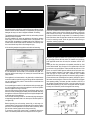
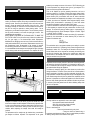
8.0 PREPARING THE APPLIANCE
Gas connection :The heater gas inlet connection is 3/8” NPT at the
regulator, located below the burner, in the center of the heater.
The appliance may be installed with or without a non-combustible hearth. If
a hearth is fitted, the size and design may be as desired.
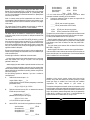
There are four possible
entry points for the gas
supply pipework to enter
the appliance firebox.
These entry points are
‘knock out’ type holes
(shown in figure 1).
Non-concealed
gas
connections may be
made using the entry
points on the base of the
firebox. A concealed
gas connection may be
made using the knock
out hole in the centre
Figure 1
back of the firebox.
Select
the
most
appropriate entry point and knock out the relevant hole.
If a concealed gas connection is to be made, the supply pipe should always
be sleeved through walls and floors using the shortest possible route.
A non-combustible shelf of any depth may be positioned above the
appliance provided it is no closer than 16” from the top of the appliance
glass panel and the wall above the appliance is non combustible.
Clearances to combustible materials
Combustible materials are defined as wood, fabrics, or other materials
likely to combust if exposed to flame. Generally, any material, which is likely
to discolour, melt or misshape when exposed to moderate heat, should be
considered as a combustible material or surface.
Clearance to the sides of the appliance are 4” but curtains, drapes and
other fabrics are not permitted within a distance of 20” of the appliance
sides. No such materials are permitted directly above the appliance
regardless of distance.
The minimum clearance to the ceiling above the appliance is 32” measured
from the top of the appliance glass panel.
Combustible materials should not be positioned directly in front of the
appliance within a distance of 40”.
For concealed supply pipe routing, pipes must (where possible) be vertical
and providing there is sufficient wall thickness available, they should be
placed in pipe chases. Horizontal pipe runs should be avoided where
possible. Prior to chasing a solid wall, an inspection should be made to note
the proximity of any cables/sockets outlets which may already be buried.
Pipes must be secured using suitable clips and protected against corrosion.
Ideally factory finished protected pipework and fittings should be used.
Joints should be kept to a minimum and compression fittings must not be
used. The pipework installation must be tested for soundness before any
protection is applied and/or the pipework and fittings are buried.
Under no circumstances should any electrical equipment e.g. plasma
screen TV sets etc. be positioned on the wall above the appliance. The
appliance is designed to be wall mounted alone and not in conjunction with
any type of combustible fire surround.
No combustible shelves should be positioned on the wall above the
appliance.
It should be established that any mirrors or picture frames etc. to be
positioned on the wall above the appliance are able to withstand prolonged
exposure to moderate heat and moisture before proceeding with their
installation.
9.0 MOUNTING THE APPLIANCE
The back of the appliance may be installed directly onto a combustible wall,
providing it is flat and does not interfere with the various vent holes in the
back panel of the appliance. The wall must be structurally sound and
constructed from a material capable of withstanding moderate heat.
Finished plaster, conventional wall paper and dry-lined plasterboard are
examples of suitable materials. Materials such as flock, blown vinyl and
embossed paper which are sensitive to even small amounts of heat should
be avoided as scorching and or discoloration may occur over time.
If the appliance is to be mounted on a dry-lined wall or a timber framed
construction wall then the integrity and ability of the wall to carry the weight
of the appliance must be confirmed. It is important in these circumstances
that any vapor control barrier is not damaged, and that any structural
members of the house frame are not damaged.
After having selected the final mounting position of the appliance, taking
into account the site requirements as specified in section 7 of these
instructions, the integrity of the wall, and the feasibility of the proposed
supply pipe routing, the firebox of appliance may be secured to the wall.
WARNING
DO NOT ALLOW ANY FANS TO BLOW DIRECTLY INTO
THE FIREPLACE. AVOID ANY DRAFTS THAT ALTER
BURNER FLAME PATTERNS.
5
9.0 MOUNTING THE APPLIANCE (continued)
WARNING
THE WALL WHERE THE APPLIANCE IS TO BE
INSTALLED MUST BE CAPABLE OF LONG-TERM
SUPPORT OF THE TOTAL LOAD OF THE APPLIANCE.
MEASURES SHOULD ALSO BE TAKEN TO ENSURE
SUFFICIENT STRENGTH TO WITHSTAND THE FORCE OF
EARTHQUAKES, VIBRATION AND OTHER EXTERNAL
FORCES.
Figure 3
10.0 CHECKING THE BURNER
To ensure customer safety, be sure to design the installation so that the
strength of both the wall and any wall fixings used are sufficient. Lennox
Hearth Products assumes absolutely no responsibility for injuries and
damages that may occur due to improper installation or handling.
There are no imitation fuel bed components to install. The appliance
features a ribbon burner which is designed to produce a continuous
band of flame over its length. The burner should be visually inspected
to ensure it is free from any foreign matter. If it is necessary to clean or
dust off the burner then the glass door should be removed by removal
of the four retaining screws. Re-fit the glass door after cleaning or
inspection, ensuring a good seal.
The appliance should not be installed until all dry wall sanding and wall
painting has been completed.
Incorrect installation can cause the appliance to fall from the wall and
cause injury. Do not block the ventilation holes of the appliance. The
wall onto which the appliance is installed must be flat. Install only on a
vertical surface. Avoid sloped surfaces. Installation onto anything other
than a vertical wall may result in fire, damage or injury.
11.0 CONNECTING A GAS LINE
A full size fitting template is supplied to assist with wall mounting.
IMPORTANT
HOLD HEATER REGULATOR WITH A WRENCH TO
PREVENT MOVEMENT WHEN CONNECTING TO INLET
PIPING.
A qualified gas appliance installer must connect the gas room heater to
the gas supply. Consult all local codes. The installer must provide an
ANSI approved manual shut off valve, flex connector and 3/8" NPT
fitting.
Route gas line using techniques and materials prescribed by local
and/or national codes. Only use pipe of 1/2"or greater size to allow full
gas volume to the gas fireplace. Undue pressure loss will occur if the
pipe is too small. An ANSI approved manual shut-off valve and union
must be installed upstream of the heater within the fireplace cavity
when rigid pipe is used. Ensure that a sediment trap is installed
upstream of the heater (figure 4) within the structure’s piping system to
prevent moisture and contaminants from passing through the pipe to
the heater controls and burner. Failure to do so could prevent the heater
from operating reliably. The heater gas inlet connection is 3/8” NPT at
the regulator, located below the burner, in the right hand side of the
heater. When tightening up the joint to the regulator hold the regulator
securely with a wrench to prevent the regulator from moving.
Figure 2
Mark the positions shown as “Fixing Points” on the wall. If the appliance
is to be mounted on the inner leaf of a conventional cavity wall, or a
solid wall, drill four holes using a 1/4” masonry bit. Insert the fiber wall
plugs provided.
If the appliance is to be mounted on a dry lined wall or a timber framed
construction wall then special cavity screw fixings will be required which
are not supplied with this product. These should be constructed from
metal and not plastic.
If a concealed gas connection is to be made ensure the gas supply pipe
is in it’s final position and can enter the appliance in the correct position
when the appliance is hung on the wall.
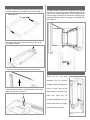
Insert the wall mounting screws into the top wall plugs, taking care to
leave the screws protruding approximately 3/8” from the wall. Now hang
the appliance onto these screws through the two keyhole shaped holes
in the back panel of the appliance.
Insert the lower mounting screws into the lower wall plugs through the
corresponding depressed holes in the lower part of the back panel. Do
not tighten fully.
Before tightening the wall mounting screws fully, at this stage it is
recommended to check the horizontal alignment of the appliance with a
spirit level, as small adjustments can still be made if necessary. When
this has been checked, tighten all four fixing screws fully.
To access the upper fixing screws insert a screwdriver through the
holes in the deflector plates above the catalyst as shown in figure 3.
Figure 4
6
The pressure test
points are located as
shown in figure 7. An
alternative burner
(mainfold test point
is located below the
left hand side of the
burner as shown in
figure 8.
The
pressure
regulator on manual
models is preset and
locked to avoid
tampering. If the
pressure is not as
specified in the
Appliance Data section on page 2,
replace the regulator
with P/N H6063.
Replace the test
point screws after
pressure
measurement
ensuring no gas
leaks. All instructions
must be handed to
the
user
for
safekeeping.
Turn on gas supply and test for gas leaks using a gas leak test solution
(also referred to as bubble leak solution).
NOTE: using a soapy water solution (50% dish soap, 50% water) is an
effective leak test solution, but it is not recommended, because the
soap residue that is left on the pipes/fittings can result in corrosion over
time.
A. Light the appliance (refer to the lighting instructions label in the control compartment or on page 11).
B. Brush all joints and connections with the gas leak test solution to
check for leaks. If bubbles are formed, or gas odor is detected, turn the
gas control knob (off/pilot/on) to the “OFF” position. Either tighten or
refasten the leaking connection, then retest as described above.
C. When the gas lines are tested and leak free, be sure to rinse off the
leak testing solution.
D. Observe the individual tongues of flame on the burner. Make sure all
ports are open and producing flame evenly across the burner. If any
ports are blocked, or partially blocked, clean out the ports.
The pressure should be checked with the gas heater burning and the
The gap between the
spark electrode and the
pilot should be 1/8” to
3/16” to produce a good
spark. There should be no
need to adjust this. If
under any circumstances
the piezo electric spark
fails, the pilot cannot be lit
manually.
1. Remove the glass panel from all packaging and lay face down on a
soft surface. Identify the top and bottom of the glass facia by
observing the orientation of the keyhole shaped slots in the facia
fixing brackets as shown in figure 10.
7
15.0 ASSEMBLY OF THE GLASS FACIA - (continued)
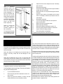
16.0 FITTING THE GLASS FACIA
2. Slide on the side pieces ensuring that the grille fixing holes (shown)
are aligned towards the top of the glass facia (as shown in figure 11).
The glass facia panel is supported by four M6 screws which protrude
from the front of the outer casing. Insert the M6 retaining screws and
ensure they are unscrewed approximately 1/8” so the keyhole shaped
holes may engage, and the facia can be hooked on. Ensuring that the
corresponding keyhole shaped holes engage the screwheads fully.
Refer to figure 15.
Grille fixing holes
Figure 11
3.Ensure the sides are neatly aligned with the glass and secure the
sides using two M6 screws for each side as shown in figure 12. Do
not overtighten the screws.
Figure 12
Figure 15
4. Position the grille within the two side pieces ensuring a neat fit.
Figure 13
17.0 FITTING THE SIDE PANELS
Remove
the
two
side
panel
Figure 16
assemblies from the protective
TOP
packaging and fit onto the sides of the
firebox as shown. Insert the M6
5. Secure the grille in position using two M6 screws and two no. 8 self
tapping screws as shown in figure 14.
retaining screws in the sides of the
Figure 14
firebox
and
ensure
they
are
unscrewed approximately 1/8” so the
keyhole shaped holes may engage,
and the sides can be hooked on.
8
Note : Front frame/facia not shown
for clarity.
4.
Inspect the burner and the catalysts and clean if necessary
with a soft brush.
5.
Disconnect the gas supply.
6.
Undo the four screws retaining the burner support brackets to
the base and rear of the firebox.
7.
Remove the burner unit, strip off the burner pipes and clean
thoroughly.
8.
Clean the in-line restrictor, pilot assembly and the burner
tube. Do not attempt to remove the pilot injector as this can
cause damage.
9.
Re-assemble components.
10.
Turn on the gas supply and leak test. Check pilot and
burner for good ignition.
11.
Refit the valve cover and retaining screws.
12.
Refit the glass door assembly.
13.
Refit the facia Refitting as described in section 15.0.
14.
Check the purpose provided ventilation is unobstructed.
15.
Light the fire and test setting pressures.
16.
Check safe operation of the appliance.
For specific servicing instructions, see relevant sections.
17.0 FITTING THE SIDE PANELS (continued)
Insert
a
screwdriver
through the holes in the
right hand side panel to
access the two M6 fixing
screws (designated ‘a’ in
figure 17) and tighten fully.
Next insert two no.8 self
tapping screws (designated
‘b’ in figure 17) through the
side panel support bracket,
and the corresponding
holes in the side of the
firebox. Tighten fully.
‘a’
‘a’
Repeat for the left hand
side panel, which is
secured by tightening the
M6 ‘a’ screws only.
The right-hand side panel
has a hinged flap to allow
access to the control knob.
‘b’
‘b’
Figure 17
20.0 SERVICING THE BURNER
18.0 BRIEFING THE CUSTOMER
DO NOT ADD LOGS OR ORNAMENTS SUCH AS PINE
CONES, VERMICULITE OR ROCK WOOL. USING
THESE ADDED ITEMS CAN CAUSE SOOTING.
First, remove the front Glass facia as described in Section 16.0 only in
reverse, remove the valve cover (4 screws) and disconnect the gas
connection inside appliance. The gas connections to the gas valve can
now be released. Undo the four screws retaining the burner brackets to
the base and rear of the firebox. The burner may now be removed.
After commissioning the appliance, the customer should be instructed
on the safe use of the appliance and the need for regular servicing.
Frequency of service depends on usage, but MUST be carried out at
least once annually.
Remove the pilot and main burner pipes and blow through to dislodge
any debris. Now remove the in line restrictor and blow through to make
sure it is entirely clear.
Advise that cleaning of the fireplace may be achieved when the
fireplace is cold using a damp cloth and mild detergent on most
surfaces.
Unclip the pilot lint gauze and clean with a soft brush. Clean the exterior
of the pilot assembly with a soft brush and blow through the flame ports
on the pilot head. Check the aeration holes are free from lint or dirt. The
pilot assembly can be removed if required by disconnecting the
electrode HT lead, gas pipe, thermocouple lead and unscrewing the
mounting screws and lifting away. The pilot assembly is a nonserviceable item and should not be taken apart. Aeration holes must be
absolutely clear internally for proper operation. NEVER MODIFY OR
BEND THE THERMOCOUPLE TO MAKE THE PILOT STAY ALIGHT.
Modifications are dangerous and can have serious unseen effects on
safety. If the pilot will not stay lit there is a problem with dirt, the gas
supply to it, or the thermocouple needs replacement.
The gas valve is a non-serviceable item. If this needs replacement,
remove the cover plate then the securing screw holding the valve
bracket in place, remove all pipe unions, and the complete valve.
Replacement must be original manufacturers parts.
Re-assemble in the reverse of removal. Ensure setting pressures are
as stated in Section 3; Appliance Data.
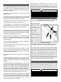
Advise that the fireplace will emit an odor for a time after initial
commissioning and that extra ventilation may be needed during this
time. A periodic visual check of the pilot flame and the burner flame
should be carried out. (Refer to figure 22).
19.0 SERVICING
A suggested procedure for servicing is detailed as follows;
Turn off the fireplace at the the gas supply. Ensure that the fireplace is
fully cold before attempting service.
1.
2.
3.
Lay out the dustsheet and tools.
Remove the front glass facia as described in section 16.0,
only in reverse.
Remove the glass door assembly (5 screws) and clean
carefully. Remove the valve cover plate (4 screws).
9
21.0 PILOT ASSEMBLY
WARNING
NO ADJUSTMENTS ARE TO BE MADE TO THE ODS
PILOT SYSTEM. TAMPERING WITH THIS SYSTEM
CAN BE EXTREMELY HAZARDOUS.
Remove the glass facia, glass panel and burner unit (as per servicing
section), lint arrestor and pilot unit by using a screwdriver to remove the
retaining screws. Clean the pilot assembly with a soft brush and blow
through. Check the aeration holes are free of any dirt or lint. Clean
thoroughly internally, the connection can be removed from the base of
the pilot unit using two spanners to make cleaning easier. Do not
damage or try to dismantle the pilot injector. The unit is factory set and
the only check necessary is to ensure the spark gap is correct. See
specifications for gas setting.
NEVER MODIFY OR BEND THE THERMOCOUPLE TO MAKE THE
PILOT STAY ALIGHT. If the pilot will not stay lit there is a problem with
dirt, the gas supply, or the thermocouple needs replacement.
Modifications are dangerous and can have a serious unseen effect on
safety and therefore MUST not be done. Replacements must be original manufacturers parts. Re-assemble in the reverse of removal.
Ensure setting pressures are as stated in Section 3; Appliance Data.
It is recommended that the catalysts are inspected for signs of damage
and dirt during routine servicing procedures. The expected life of the
22.0 CATALYSTS
WARNING
DO NOT BLOCK THE CATALYSTS OR THE
APPLIANCE OUTLET GRILLE. BLOCKAGE MAY
CAUSE HIGH CARBON MONOXIDE LEVELS AND/OR
BREAKAGE OF THE GLASS FACIA PANEL.
DO NOT BLOCK
THESE AREAS
Figure 18
emitted by the catalytic converters is in excess of 700 oF. Measuring gas
of this temperature may damage some types of gas analyzers. If in
doubt consult the equipment manufacturer.
Turn on the fireplace as per the operating instructions, and run at
maximum setting for 15 minutes. Position gas sample probe directly
over a catalyst via the outlet grille, on top of the appliance. Record the
carbon dioxide (CO2) concentration and then the carbon monoxide
(CO) concentration as displayed by the analyzer - also noting the units
in which the values are expressed. Most analyzers display carbon
dioxide (CO2) concentrations in percentage (%) terms and carbon
monoxide concentration in parts per million (ppm) terms.
In order to calculate the combustion ratio for the appliance (CO/CO2) it
is first necessary to express both gas concentrations in terms of percentage. To convert from parts per million (ppm) to a percentage (%)
divide the ppm figure by 10,000. Examples : 35ppm = 0.0035%, 15ppm
= 0.0015%, 5ppm = 0.0005%.
Now divide the concentration of carbon monoxide (CO) expressed in
percent by the concentration of carbon dioxide (CO2) to obtain the
appliance combustion ratio.
CO (%)
CO2 (%) = ratio
The combustion ratio of the gasses emitted by the catalytic convertor
should not exceed 0.0015. If replacing, firstly, remove the glass facia as
described in section 15.0. The catalysts are located on the top of the
internal firebox and can be removed be unscrewing the retaining nuts
securing the clamping plate. Remove the catalysts and seals and
discard. Refit a new catalysts and seals in reverse order, ensure the
catalysts and door have good seals.
23.0 TESTING FOR FIREBOX LEAKAGE
Appliances that are several years old or have been extensively dismantled should be checked for soundness. It is important that all the products of combustion pass through the catalytic converters at the top of
the firebox before leaving the appliance.
The firebox is heated by lighting for a few minutes to provide a flow
through the firebox. The burner is then shut off and a smoke pellet or
match introduced at the base of the fire underneath the burner tray.
Large quantities of smoke will emerge from the top of the appliance, but
none should emerge from the joints or gasket faces, especially around
the door. It is important to note that the appliance can never be expected to be 100% smoke tight and small quantities of smoke may be seen
in corners of joints and gasket faces etc without affecting safety when
the fire is in operation.
24.0 CLEANING
WARNING
WARNING
DO NOT OPERATE THE APPLIANCE WITH THE
CATALYST UNITS REMOVED.
catalysts is in excess of 11,000 hours (10 years of normal use). After
this time the catalyst should be replaced. If there are any deposits of dirt
or soot on the catalysts they should be cleaned with a soft brush and a
vacuum cleaner. If removed for cleaning ensure the seals are in good
condition before replacing the catalyst. New seals will usually be
required.
The performance of the catalyst may be checked using a combustion
gas analyzer as follows. Important: The temperature of the gases
TURN OFF THE UNVENTED GAS ROOM HEATER
AND ALLOW TO COOL BEFORE CLEANING.
GLASS PANEL -This can be cleaned with a suitable glass cleaner. The
following solutions are approved for use to clean glass.
• Non-ammonia based household cleaner
• 50% -50% mix of white vinegar and water
• Gas fireplace/stove glass cleaner
Test on a small area first.
PAINTED AREAS - These can be cleaned using a dry cloth.
FINISHED METAL AREAS - These can either be cleaned using a
proprietary metal cleaner or baby oil. Test on a small hidden part before
10 cleaning. Always clean in the direction of the grain.
FOR YOUR SAFETY READ BEFORE LIGHTING
WARNING
IF YOU DO NOT FOLLOW THESE INSTRUCTIONS EXACTLY, A FIRE OR EXPLOSION MAY RESULT CAUSING
PROPERTY DAMAGE, PERSONAL INJURY OR LOSS OF LIFE.
A.
This heater has a pilot which must be lit by hand. When
lighting the pilot, follow these instructions exactly.
• Immediately call your gas supplier from a neighbor’s phone.
Follow the gas supplier’s instructions.
B.
BEFORE OPERATING smell all around the heater area for gas.
Be sure to smell next to the floor because some gas is
heavier than air and will settle on the floor.
• If you cannot reach your gas supplier, call the fire department.
C.
Use only your hand to push in or turn the gas control knob.
Never use tools. If the knob will not push in or turn by hand, do
not try to repair it, call a qualified service technician. Forced or
attempted repair may result in a fire or explosion.
D.
Do not use this heater if any part has been under water.
Immediately call a qualified service technician to inspect the
appliance and to replace any part of the control system and
any gas control which has been under water.
WHAT TO DO IF YOU SMELL GAS
• Do not try to light any appliance.
• Do not touch any electric switch; do not use any phone in
your building.
25.0 LIGHTING INSTRUCTIONS
8. Continue turning counterclockwise
through the spark
click to the PILOT light position, ensuring the pilot has lit. If not, turn the
knob fully clockwise, and repeat.
1. Stop! Read the safety information above.
2. Make sure manual shut-off valve is fully open.
9. Hold the control knob in for a further 10 seconds to prevent the flame
failure detector from shutting off the gas while the probe is warming up.
3. Open the access panel.
4. Depress control knob in and turn clockwise
“OFF” position ( Figure 19 ).
to the
10. Release the control knob while turning counterclockwise
to the preferred setting. Close the control access panel.
5. Wait 5 minutes to clear out any gas. Then smell for gas, including near
the floor. If you smell gas, STOP! Follow the safety instructions in “What
to do if you smell gas” under section ‘B’ above. If you do not smell gas,
go to next step.
• If the knob does not pop out when released, stop and immediately call
your service technician or gas supplier.
• If the pilot will not stay lit after several tries, depress and turn the gas
control knob clockwise
to “OFF”and wait 30 seconds.
Depress and turn knob counterclockwise
to “SPARK” and
ignite the heater again. If your pilot does not relight depress and turn
control knob clockwise
to “OFF” and call your service
technician or gas supplier.
6. The pilot is located on the left side behind the burner (Figure 20).
7. Depress control knob in and turn counterclockwise
to the “SPARK” position ( Figure 19 ) and hold there for a few seconds.
Note: If you are running the heater for the first time or after an extended
period of non use it will be necessary to press the control knob all the
way in for 30 seconds to allow air to bleed out of the gas piping.
11. Wait 30 seconds before readjusting the heater when the control knob
has been turned down to a lower setting.
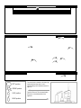
26.0 TO TURN OFF GAS TO APPLIANCE
1. Open the control access panel.
Figure 19
‘OFF’ position
‘SPARK’ position
‘LOW’ position
2. Depress and turn control knob clockwise
position (Figure 19). Close the control access panel.
The control knob is located on the lower right
hand side of the outer case. It is of a
spherical design and is marked as shown in
figure 19
Figure 20: Pilot unit. This is located behind
the burner, on the left-hand side of the
appliance.
‘HIGH’ position
11
Figure 20
to the “OFF”
27.0 TROUBLESHOOTING GUIDE
Fire sparks but pilot does not light
No gas to Pilot, check the gas line connections.
Air not fully purged, repurge supply or wait longer.
Spark grounding to metal work, reset gap correctly.
Blocked pilot, clean out internally.
Pilot lights but then goes out
Severe restriction in gas supply: clear obstruction.
Faulty thermocouple, replace pilot unit.
Blocked pilot, clean out.
Blocked lint gauze, clean.
Hold control knob in for longer.
Check control knob does not foul data plate.
If the pilot will not stay lit there is a problem with dirt, the gas supply, or the thermocouple needs
replacement. Modifications are dangerous and can have a serious unseen effect on safety.
NEVER MODIFY OR BEND THE THERMOCOUPLE TO MAKE THE PILOT STAY LIT.
Fire does not spark at pilot
HT lead detached, refit.
Check the spark gap (see section 14.0).
Faulty piezo unit, replace.
Debris shorting out electrode, clean.
Spark shorting to metalwork under tray, realign HT lead.
Fire runs for a time and then cuts off
Loose or faulty thermocouple, rectify.
Blocked pilot, clean out.
Dirt or lint in pilot aeration hole or on the lint gauze, clean thoroughly.
If the pilot will not stay lit there is a problem with dirt, the gas supply, or the thermocouple needs
replacement. Modifications are dangerous and can have a serious unseen effect on safety.
NEVER MODIFY OR BEND THE THERMOCOUPLE TO MAKE THE PILOT STAY LIT.
Pilot flame shrinks when fire is on high
Poor gas flow to fire, check pressure with fire on high.
If pressure is low, remove any restriction in pipework or valve.
Check all pipework is adequately sized.
Check meter pressure is adequate.
If the pilot will not stay lit there is a problem with dirt, the gas supply, or the thermocouple needs
replacement. Modifications are dangerous and can have a serious unseen effect on safety.
NEVER MODIFY OR BEND THE THERMOCOUPLE TO MAKE THE PILOT STAY LIT.
Fire smells when first lit or in use
Newness smell from brand new appliance.
Leakage occurring. Carry out leakage test and rectify any problems.
Combustible materials used in incorrect positions.
Unit may require a service to remove dust from catalysts.
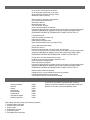
28.0 REPLACEMENT PARTS
Description
Glass door assembly
Gas valve
Catalyst
Pilot assembly
Burner assembly
Catalyst seal kit
Inlet pressure regulator
Decorative glass facia
Catalog No.
H6055
H6059
H6060
H6061
H6056
H6062
H6063
H6068
If you encounter any problems, require spare parts, or have any
questions concerning the installation of the heater please contact your
distributor. For the name of your nearest distributor contact:
LENNOX HEARTH PRODUCTS
1110 West Taft Avenue
Orange, CA 92865
Phone: 1-800-9-Lennox
visit us at www.Lennox.com
When ordering spare parts, always give the following information:
1. The model number of the heater.
2. The serial number of the heater.
3. The part number.
4. The description of the part.
5. The quantity required.
6. The installation date of the heater.
12
29.0 POSITIONING OF FIELD REMOVABLE PARTS
WARNING
Figure 21
FAILURE TO POSITION THE PARTS
IN ACCORDANCE WITH THESE
DIAGRAMS OR FAILURE TO USE
ONLY PARTS SPECIFICALLY
APPROVED WITH THIS HEATER
MAY RESULT IN
PROPERTY
DAMAGE OR PERSONAL INJURY.
Figure 21: Removal and refitting of glass
door assembly and burner assembly.
4 off burner installation positions
Figure 22
13
Figure 22 : Visual check
for correct pilot flame.
Lennox Hearth Products Gas Fireplaces, Stoves and Inserts
20 Year Limited Warranty
THE WARRANTY
Lennox Hearth Products ("LHP") warrants your gas fireplace, appliance, stove or insert ("Product") to be free from defects in materials and workmanship at the time of manufacture. After
installation, if any of the components manufactured by LHP in the Product are found to be defective in materials or workmanship during the twenty year warranty period and while the
Product remains at the site of the original installation, LHP will, at its option, replace or repair the defective components. LHP will also pay for reasonable labor costs incurred in replacing
or repairing such components for a period of one year from the date of installation. THERE ARE EXCLUSIONS AND LIMITATIONS to this Limited Warranty as described herein.
EXCLUSIONS AND LIMITATIONS
This Limited Warranty applies only if the Product is installed in the United States or Canada and only if operated and maintained in accordance with the printed instructions accompanying
the Product and in compliance with all applicable installation and building codes and good trade practices. If repair or replacement is not commercially practical, LHP will, at its option,
refund the purchase price of the LHP Product.
The firebox and enclosure are warranted for twenty (20) years from the date of installation as follows: First year - parts at no charge and reasonable labor charges. Second through fifth
year - parts only at no charge. Sixth through twentieth year - parts only at 50% of the then current list price. Vent components, brass components, paint, optional accessories and optional
glass doors are excluded from this Limited Warranty. A separate limited warranty is available from LHP for optional glass doors manufactured by LHP. The following components are
NOT warranted for 20 years but are warranted as follows:
Controls - repair or replacement for one year from the date of installation.
Burner - repair or replacement for one year from the date of installation.
Glass Components - repair or replacement for one year from the date of installation. Ceramic glass is warranted against thermal breakage only for a period of
two years from date of installation.
Gaskets - repair or replacement for one year from the date of installation.
Logs - repair or replacement for one year from the date of installation.
Catalyst - two years parts and labor, 3-5th year, parts only from the date of installation.
We will not be responsible for: (a) damages caused by accident, riot, fire, flood or acts of God; (b) damages caused by abuse, negligence, misuse, or unauthorized alteration or repair
of the Product affecting its stability or performance (The Product must be subject to normal use. The Product is designed to burn either natural or propane gas only. Burning conventional
fuels such as wood, coal or any other solid fuel will cause damage to the Product, will produce excessive temperatures and will result in a fire hazard); (c) damages caused by failing to
provide proper maintenance and service in accordance with the instructions provided with the Product; (d) damages, repairs or inefficiency resulting from faulty installation or application
of the Product.
This Limited Warranty covers only parts and labor as provided herein. In no case shall LHP be responsible for materials, components or construction which are not manufactured or
supplied by LHP or for the labor necessary to install, repair or remove such materials, components or construction. All replacement or repair components will be shipped F.O.B. the
nearest LHP factory.
LIMITATION ON LIABILITY
It is expressly agreed and understood that LHP's sole obligation and purchaser's exclusive remedy under this warranty, under any other warranty, expressed or implied, or
in contract, tort or otherwise, shall be limited to replacement, repair, or refund, as specified herein. In no event shall LHP be liable for any incidental or consequential
damages caused by defects in the Products, whether such damage occurs or is discovered before or after replacement or repair, and whether such damage is caused by
LHP's negligence. LHP has not made and does not make any representation or warranty of fitness for a particular use or purpose, and there is no implied condition of fitness
for a particular use or purpose.
We make no express warranties except as stated in this Limited Warranty. The duration of any implied warranty is limited to the duration of this expressed warranty.
No one is authorized to change this Limited Warranty or to create for us any other obligation or liability in connection with the Product. Some states and provinces do not
allow the exclusion or limitation of incidental or consequential damages, so the above limitations or exclusions may not apply to you. The provisions of this Limited
Warranty are in addition to and not a modification of or substraction from any statutory warranties and other rights and remedies provided by law.
INVESTIGATION OF CLAIMS AGAINST WARRANTY
LHP reserves the right to investigate any and all claims against this Limited Warranty and to decide upon method of settlement.
LHP NOT RESPONSIBLE FOR WORK DONE WITHOUT WRITTEN CONSENT
To receive the benefits and advantages described in this Limited Warranty, the appliance must be installed and repaired by a licensed contractor approved by LHP. Contact LHP at the
address provided herein to obtain a listing of approved dealers. LHP shall in no event be responsible for any warranty work done by a contractor that is not approved without first obtaining
LHP's prior written consent.
HOW TO REGISTER A CLAIM AGAINST WARRANTY
In order for any claim under this Warranty to be valid, LHP must be notified of the claimed defect in writing as soon as reasonably possible after the
defect is discovered. Notices should be directed to LHP, attention Customer Service Department, 1110 West Taft Avenue, Orange, CA 92865. Claims in writing should include the date
of installation and a description of the defect.
NOTE: DIAGRAMS & ILLUSTRATIONS ARE NOT TO SCALE
Lennox reserves the right to make changes at any time, without notice, in design,
materials, specifications, prices and also to discontinue colors, styles and products.
Consult your local dealer or distributor for fireplace code information.
LENNOX HEARTH PRODUCTS
P/N 850,054M REV. NC 04/2007
1110 West Taft Avenue • Orange, CA 92865