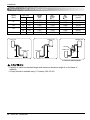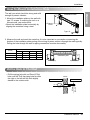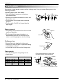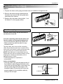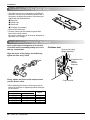
1
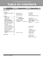
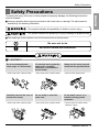
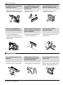
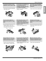
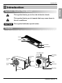
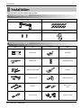
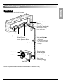
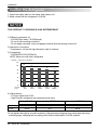
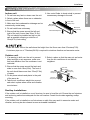
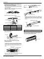
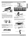
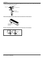
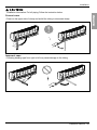
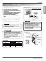
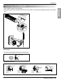
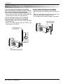
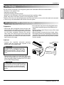
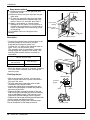
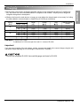
http://www.lgservice.com
INSTALLATION MANUAL
FRANÇAIS
LG
Room Air Conditioner
ENGLISH
LG
ESPAÑOL
IMPORTANT
• Please read this instruction manual completely before
installing the product.
• When the power cord is damaged, replacement should be
performed by authorized personnel only.
• Installation work must be performed in accordance with
the national wiring standards by authorized personnel
only.
• Please retain this installation manual for future reference
after reading it thoroughly.
Room Air Conditioner Installation Manual
TABLE OF CONTENTS
Installation
Requirements
Required Parts
Required Tools
Safety Precautions .........................3
Introduction .....................................9
Symbols Ued in This Manual......9
Features .......................................9
Installation .....................................10
Installation Parts ........................10
Installation Tools ........................10
Installation Map..........................11
Confirm The Refrigerant ...........12
Select The Best Location .........13
Piping Length And Elevation.....14
How To Mount Installation Plate ..15
Drill a Hole In The Wall..............15
Flaring Work...............................16
Connecting The Piping..............17
Connection Of The Drain Hose...22
Connection Of Piping -Outdoor...22
Connection Of The Cable .........23
Checking The Drainage ............25
Forming The Piping ...................26
Air Purging .................................27
Air Purging With Vacuum Pump..27
Charging.....................................29
Test Running .................................30
2 Room Air Conditioner
❏ Installation plate
❏ Four type "A" screws
❏ Connecting cable
❏ Pipes: Suction line
Evaporator line
(Refer to page 13)
❏ Insulation materials
❏ Additional drain pipe
(Outer Diameter .........15.5mm(0.61in))
❏ Level gauge
❏ Screwdriver
❏ Electric drill
❏ Hole core drill(ø70mm(2.76in))
❏ Flaring tool set
❏ Specified torque wrenches
4.2kg.m, 6.6kg.m
(different depending on model No.)
(Refer to page 17)
❏ Spanner .....................Half union
❏ A glass of water
❏ Screw driver
❏ Two type "B" screws
❏ Hexagonal
wrench(4mm(0.16in))
❏ Gas Leak Detector
❏ Vacuum pump
❏ Manifold Gauge
❏ Owner's manual
❏ Thermometer
❏ Remote Control Holder
Safety Precautions
Safety Precautions
■ Incorrect operation due to ignoring instruction will cause harm or damage. The seriousness is
classified by the following indications.
This symbol indicates the possibility of death or serious injury.
This symbol indicates the possibility of injury or damage to properties only.
■ The meanings of the symbols used in this manual are as shown below.
Be sure not to do.
Be sure to follow the instruction.
■ Installation
Do not use damaged power
cords, plugs, or a loose socket.
For electrical work, contact the
dealer, seller, a qualified
electrician, or an Authorized
Service Center.
Always use the power plug and
socket with the ground terminal.
• There is risk of fire or electric shock.
• There is risk of fire or electric shock.
• There is risk of electric shock.
Install the panel and the cover of
control box securely.
Do not modify or extend the
power cord.
Do not install, remove, or reinstall the unit by yourself
(customer).
• There is risk of fire or electric shock.
• There is risk of fire or electric shock.
• There is risk of fire, electric shock,
explosion or injury.
Installation Manual 3
ENGLISH
To prevent the injury of the user or other people and property damage, the following instructions
must be followed.
Safety Precautions
Be cautious when unpacking and
installing the product.
For installation, always contact
the dealer or an Authorized
Service Center.
Do not install the product on a
defective installation stand.
• Shape edges could cause injury. Be
especially careful of the sharp edges.
• There is risk of fire, electric shock,
explosion, or injury.
• It may cause injury, accident, or
damage to the product.
Be sure the installation area
does not deteriorate with age.
Install the indoor unit on the wall
where the height from the floors
more then 8ft(2.4m)
Do not handle the pipe by
yourself(customer)
• If the base collapses, the air
conditioner could fall with it, causing
property damage, product failure, and
personal injury.
• There are sharp moving parts that
could cause personal injury.
• High-Pressure refrigent may cause
personal injury.
8ft(2.4m)
■ Operation
Use a dedicated outlet for this
appliance.
Grasp the plug to remove the
cord from the outlet. Do not
touch it with wet hands.
• There is risk of fire or electric shock.
• There is risk of fire or electric shock.
4 Room Air Conditioner
Do not allow water to run into
electric part.
• There is risk of fire, failure of the
product, and/or electric shock.
Safety Precautions
Do not place a heater or other
appliances near the power cable.
• Moisture may condense and wet or
damage furnishings.
Do not store of use flammable
gas or combustibles near the air
conditioner.
• There is risk of fire or product failure.
x
Wa Thinner
Do not use the product in a
tightly closed space for a long
time.
When flammable gas leaks, turn off
the gas and open a window for
ventilation before turning the product
on. Do not use the telephone or turn
switches on or off.
Unplug the unit if strange
sounds odors or smoke comes
from it.
• Oxygen deficiency could occur.
• Some ventilation by opeing window
is necessary for the fresh air.
• There is risk of explosion or fire.
• There is risk of fireproduct failure and/or
electric shock.
Stop operation and close any
window in storm or hurricane.
before the hurricane arrives.
Do not open the inlet grill of the
product during operation. (Do
not touch the electrostatic filter,
if the unit is so equipped.)
When the product is soaked
(flooded or submerged), contact
an Authorized Service Center.
• There is risk of property damage,
failure of product, or electric shock.
• There is risk of physical injury, electric
shock, or product.
• There is risk of electrical shock.
Installation Manual 5
ENGLISH
• There is risk of fire, failure of the product,
and/or electric shock.
Do not let the air conditioner run
for a long time when the
humidity is very high and a door
or a window is left open.
Safety Precautions
Ventilate the product from time to
time when operating it together
with a stove, etc.
Unplug the appliance before
performing cleaning or
maintenance.
When the product is not be used
for a long time disconnect the
power supply plug or turn off the
breaker.
• There is risk of fire or electrical shock.
• There is risk of electric shock.
• There is risk of product damage or
failure, or unintended operation.
Take care to ensure that nobody could step on or
fall onto the outdoor unit.
Do not insert hands or other objects through the air
inlet or outlet while the air conditioner is plugged
in.
• There could result in personal injury and product damage.
• There are sharp and moving parts that could cause
personal injury.
■ Installation
Always check for gas(refrigerant)
leakage after installation or
repair of product.
Install the drain hose to ensure
that water is drained away
properly.
Keep level even when installing
the product.
• Low refrigerant levels may cause
product failure.
• A bad connection may cause water
leakage.
• To avoid vibration or water leakage.
90˚
6 Room Air Conditioner
Safety Precautions
Use two or more people to lift
and transport the air conditioner
Do not install the product where
it will be exposed to sea wind
(salt spray) directly.
• It may cause a problem for your
neighbors.
• Avoid personal injury.
• It may cause corrosion in the product.
Corrosion, particularly on the
condenser and evaporator fins, could
cause product malfunction or
inefficient operation.
Do not direct airflow at room
occupants.
Do not use the product for special
purposes, such as preserving
foods, works of art, etc. It is a
consumer air conditioner, not a
precision refrigeration system.
Do not block the inlet or outlet of
air flow.
• This could damage your health.
• There is risk of damage or loss of
property.
• It may cause product failure.
Use a soft cloth to clean.
Do not use harsh detergents,
solvents, etc.
Do not touch the metal parts of
the product when removing the
air filter. They are very sharp!
Do not step on or put anything
on the product. (outdoor unit)
• There is risk of fire, electric shock
or damage to the plastic parts of the
product.
• There is risk of personal injury.
• There is risk of personal injury and
failure of product.
■ Operation
Installation Manual 7
ENGLISH
Do not install the product where
the noise or hot air from the
outdoor unit could damage the
neighborhoods.
Safety Precautions
Always insert the filter securely. Clean the filter
every two weeks or more often if necessary.
Do not drink the water drained from the unit.
• A dirty filter reduces the efficiency of the air conditioner and
could cause product malfunction or damage.
• It is not sanitary and could cause serious health issues.
Use a firm stool or ladder when cleaning or
maintaining the air conditioner.
Replace all the batteries in the remote.
• Be careful and avoid personal injury.
• There is risk of fire or explosion.
■ Disuse
Do not recharge or disassemble the batteries. Do
not dispose of batteries in a fire.
If the liquid from the batteries gets onto your skin
or clothes, wash it well with clean water. Do not
use the remote if the batteries have leaked.
• They may burn or explode.
• The chemicals in batteries could cause burns or other
health hazards.
8 Room Air Conditioner
Introduction
Introduction
ENGLISH
Symbols Used In This Manual
This symbol alerts you to the risk of electric shock.
This symbol alerts you to hazards that may cause harm to
the air conditioner.
NOTICE
This symbol indicates special notes.
Features
Air Inlet
Air Filter
Front Panel
Signal Receptor
Air Intake Vents
Connecting
Wires
Connecting
Wires
Air Intake
Vents
Piping
Piping
Air Outlet
Vents
Drain Hose
Drain Hose
Air Outlet Vents
Base Plate
Base Plate
Installation Manual 9
Installation
Installation
Read carefully, and then follow step by step.
Installation Parts
Installation plate
Type "A" screw and plastic anchor
Type "B" screw
Remote Control Holder
Installation Tools
Figure
10 Room Air Conditioner
Name
Figure
Name
Screw driver
Ohmmeter
Electric Drill
Hexagonal wrench
Measuring Tape, Knife
Ammeter
Hole Core Drill
Gas Leak Detector
Spanner
Thermometer,
Level
Torque wrench
Flaring Tool Set
Installation
Installation Map
ENGLISH
NOTICE
Installation parts you should purchase.
Installation Plate
Sleeve
Bushing-Sleeve
Putty(Gum Type Sealer)
Bend the pipe as closely
on the wall as possible,
but be careful that it
doesn't break.
Air Discarge
Vertical Air deflector
Operation Indication Lamps/
Signal Receptor
Vinyl tape(Wide)
Forced Operation Button
Saddle
• Apply after carrying out a
drainage test.
• To carry out the drainage
test, remove the air filters
and pour water into the heat
exchanger.
Gas side piping
Liquid side piping
Additional drain pipe
Air Inlet Vents
Air Outlet Vents
Drain Hose
Connecting cable
Base Plate
NOTE: refrigerant line wall thickness must be at least 0.8 mm (0.031 inch)
Installation Manual 11
Installation
Confirm The Refrigerant
1. Check the quality label on the indoor and outdoor unit.
2. Make certain that the refrigerant is R-410A.
NOTICE
THIS PRODUCT CONTAINS R-410A REFRIGERANT
1) Different compressor oil
- R-410A(Polyol ester) / R-22(Mineral).
- Do not mix the existing mineral oil.
- Do not apply used pipe, tools and gauges covered with the existing mineral oil.
2) Absorption of moisture
-Compressor’s oil has the high absorption rate of moisture.
3) Composition
- R-410A(R32:R125=50:50wt%).
NOTE: Never mix with other refrigerants
Example : Split type 12,000 Btu/h
120
100
93
100
89
84
76
80
60
40
20
0
R-410A
R-22
100%
0%
70%
50%
30%
30%
50%
70%
0%
100%
4) High pressure.
- 1.6 times higher than R-22.
- High Pressure refrigerant may cause personal injury.
R-410A
R-22
Boiling Pt.(°C)
Vapor pressure(25°C)(kg f/cnf)
Vapor density(25°C)(kg/m2)
-51.4
-40.8
15.9
9.6
64
44.4
Do not handle the pipe by yourself (customer) High-pressure refrigerant may cause personal injury.
- manifold gauge ,charging and any piping tools must be dedicated to R-410A systems.
12 Room Air Conditioner
Installation
Select The Best Location
1. Do not have any heat or steam near the unit.
6. Use a stud finder to locate studs to prevent
unnecessary damage to the wall.
2. Select a place where there are no obstacles
in front of the unit.
3. Make sure that condensation drainage can be
conveniently routed away.
More than
30cm(11.8in)
More than
30cm(11.8in)
4. Do not install near a doorway.
5. Ensure that the space around the left and
right of the unit is more than 30cm(11.8in).
The unit should be installed as high on the
wall as possible, allowing a minimum of
12cm(4.7in) from ceiling.
More than
12cm(4.7in)
More than 8ft(2.4m)
Install the indoor unit on the wall where the height from the floors more than 2.3meters(7.6ft).
A minimum pipe run of 7.5meters(24.6ft) is required to minimize vibration and excessive noise.
Outdoor unit
1. If an awning is built over the unit to prevent
direct sunlight or rain exposure, make sure
that heat radiation from the condenser is not
restricted.
2. Ensure that the space around the back and
sides is more than 10cm(3.9in). The front of
the unit should have more than 70cm(27.6in)
of space.
3. Do not place animals and plants in the path
of the warm air.
5. Select a place so that the warm air and noise
from the air conditioner do not disturb
neighbors.
More than
10cm(3.9in)
More than
70cm(27.6in)
More than
60cm(23.6in)
More than
10cm(3.9in)
More than
60cm(23.6in)
4. Take the air conditioner weight into account
and select a place where noise and vibration
are minimum.
Rooftop Installations
If the outdoor unit is installed on a roof structure, be sure to level the unit. Ensure the roof structure
and anchoring method are adequate for the unit location. Consult local codes regarding rooftop
mounting.
If the outdoor unit is installed on roof structures or walls, this may result in excessive noise and
vibration, and may be also classed as non serviceable installation.
Installation Manual 13
ENGLISH
Indoor unit
Installation
Piping Length And Elevation
Capacity
(Btu/h)
Evap
Standard
Length
m(ft)
Max.
Elevation
B m(ft)
Max.
length
A m(ft)
Additional Refrigerant
g/m(oz/ft)
1/4"
7.5(25)
7.5(25)
15(49)
20(0.22)
Pipe Size
Suction
3/8"
9k
1/2"
1/4"
7.5(25)
7.5(25)
15(49)
20(0.22)
12k
1/2"
1/4"
7.5(25)
7.5(25)
15(49)
20(0.22)
18k
1/2"
1/4"
7.5(25)
15(49)
30(98)
20(0.22)
5/8"
1/4"
7.5(25)
7.5(25)
15(49)
20(0.22)
5/8"
1/4"
7.5(25)
7.5(25)
15(49)
20(0.22)
24k
Outdoor unit
Indoor unit
B
Oil trap
A
A
Outdoor unit
Indoor unit
Outdoor unit
B
A
Indoor unit
B
In case more than 5m(16.4ft)
• Capacity is based on standard length and maximum allowance length is on the basis of
reliability.
• Oil trap should be installed every 5~7meters (16.4~23.0ft).
14 Room Air Conditioner
Installation
How To Mount Installation Plate
1. Mount the installation plate on the wall with
type "A" screws. If mounting the unit on a
concrete wall, use anchor bolts.
• Mount the installation plate horizontally by
aligning the centerline using a level.
ENGLISH
The wall you select should be strong and solid
enough to prevent vibration
Installation Plate
Chassis
Hook
Type “A”
2. Measure the wall and mark the centerline. It is also important to use caution concerning the
location of the installation plate-routing of the wiring to power outlets is through the walls typically.
Drilling the hole through the wall for piping connections must be done safely.
CHASSIS
(Grade)
Distance (mm)
S4
A
50
B
105
C
59
D
105
SE
S5
65
95
110
122
85
235
110
122
Installation plate
D
Ø70mm
B
A
C
Left rear piping
Ø70mm
Right rear piping
Drill a Hole In The Wall
WALL
Outdoor
5-7mm
Indoor
(0.2~0.3")
• Drill the piping hole with a ø70mm(2.76in)
hole core drill. Drill the piping hole at either
the right or the left with the hole slightly
slanted to the outdoor side.
Installation Manual 15
Installation
Flaring Work
Main cause for gas leakage is due to defect in flaring work. Carry out correct flaring work in the
following procedure.
Cut the pipes and the cable.
1. Use the piping kit accessory or the pipes
purchased locally.
2. Measure the distance between the indoor and
the outdoor unit.
3. Cut the pipes a little longer than measured
distance.
4. Cut the cable 1.5m(59.1in) longer than the
pipe length.
Copper
pipe
Slanted Uneven Rough
90¡
Burrs removal
Pipe
1. Completely remove all burrs from the cut cross
section of pipe/tube.
Reamer
2. Put the end of the copper tube/pipe in a
downward direction as you remove burrs in
order to avoid dropping burrs into the tubing.
Point down
Putting nut on
Flare nut
• Remove flare nuts attached to indoor and
outdoor unit, then put them on pipe/tube having
completed burr removal.
(not possible to put them on after flaring work)
Copper tube
Flaring work
Outside diameter
mm
inch
Ø6.35
1/4
Ø9.52
3/8
Ø12.7
1/2
Ø15.88
5/8
A
mm
0~0.5
0~0.5
0~0.5
0~1.0
inch
0~0.020
0~0.020
0~0.020
0~0.039
Firmly hold copper pipe in a die in the
dimension shown in the table above.
Bar
Handle
"A"
• Carry out flaring work using flaring tool as
shown below.
Bar
Yoke
Cone
Copper pipe
Clamp handle
16 Room Air Conditioner
Red arrow mark
Installation
Connecting The
the Piping
Piping
ENGLISH
Indoor
1. Prepare the indoor unit's piping and drain hose for installation through the wall.
2. Remove the plastic tubing retainer(see the
illustration by) and pull the tubing and drain
hose away from chassis.
3. Replace only the plastic tubing holder 1, not
the holder 2 in the original position.
For left rear piping
Route the indoor tubing and the drain hose in
the direction of rear left.
1
2
Connecting
cable
Insert the connecting cable into the indoor unit
from the outdoor unit through the piping hole.
Drain pipe
• Do not connect the cable to the indoor unit.
• Make a small loop with the cable for easy
connection later.
Tape the tubing, drain hose and the connecting
cable. Be sure that the drain hose is located at the
lowest side of the bundle. Locating at the upper side
can cause drain pan to overflow inside the unit.
NOTE: If the drain hose is routed inside the room,
insulate the hose with an insulation material* so that
dripping from "sweating"(condensation) will not
damage furniture or floors.
*Foamed polyethylene or equivalent is
recommended.
Indoor unit installation
• Hook the indoor unit onto the upper portion of
the installation plate.(Engage the three hooks
of the rear top and rear lower of the indoor unit
with the upper edge and lower edge of the
installation plate.) Ensure that the hooks are
properly seated on the installation plate by
moving it left and right.
Indoor unit
Spacer
Installation plate
8cm
Installation Manual 17
Installation
Connecting the pipings to the indoor unit
and drain hose to drain pipe.
• Put a couple drops of refrigerant oil on the face of
the flare before assembling taking care not to add
any contaminants.
• Align the center of the pipings and sufficiently
tighten the flare nut by hand.
Indoor
unit pipe
Connection
pipe
Vinyl tape
(wide)
Wrap with vinyl tape
Connecting cable
Pipe
Indoor unit tubing
Flare nut
Pipings
Vinyl tape(narrow)
• Tighten the flare nut with a wrench.
Indoor unit tubing
Torque wrench
Connection pipe
• Bundle the piping and drain hose together by
wrapping them with vinyl tape over the range
within which they fit into the rear piping housing
section.
Wrap with vinyl tape
Flare nut
Pipe
Spanner (fixed)
Outside diameter
mm
inch
Ø6.35
Ø9.52
Ø12.7
Ø15.88
Torque
1/4
3/8
1/2
5/8
1.8
4.2
5.5
6.6
• When extending the drain hose at the indoor unit,
install the drain pipe.
Vinyl tape(wide)
Drain hose
For right rear piping
Route the indoor tubing and the drain hose to
the required piping hole position.
Drain pipe
Indoor unit drain hose
Adhesive
Vinyl tape(narrow)
Wrap the insulation material around the
connecting portion.
• Overlap the connection pipe insulation material
and the indoor unit pipe insulation material. Bind
them together with vinyl tape so that there is no
gap.
Plastic bands Insulation material
• Wrap the area which accommodates the rear
piping housing section with vinyl tape.
18 Room Air Conditioner
Drain hose
Installation
Insert the connecting cable into the indoor unit.
• Don't connect the cable to the indoor unit.
• Make a small loop with the cable for easy
connection later.
Flare nut
Connection pipe
Torque wrench
Indoor unit tubing
• Connecting cable
Outside diameter
Torque
Ø6.35
1/4
1.8
Ø9.52
3/8
4.2
Ø12.7
1/2
5.5
Ø15.88
5/8
6.6
• When extending the drain hose at the indoor unit,
install the drain pipe.
Tape
Connecting
pipe
Drain hose
Connecting cable
Drain hose
Indoor unit installation
• Hook the indoor unit onto the upper portion of
the installation plate.(Engage the three hooks of
the rear top and rear lower of the indoor unit with
the upper edge and lower edge of the installation
plate.) Ensure that the hooks are properly
seated on the installation plate by moving it left
and right.
Indoor unit drain hose
Adhesive
Vinyl tape (narrow)
Wrap the insulation material around the
connecting portion.
• Overlap the connection pipe heat insulation and the
indoor unit pipe heat insulation material. Bind them
together with vinyl tape so that there is no gap.
Connecting
cable
Plastic bands Insulation material
Drain hose
Connecting the pipings to the indoor unit and
the drain hose to drain pipe.
• Put a couple drops of refrigerant oil on the face of
the flare before assembling taking care not to add
any contaminants
• Align the center of the pipings and sufficiently
tighten the flare nut by hand.
• Wrap the area which accommodates the rear
piping housing section with vinyl tape.
Indoor
unit piping
Connection
pipe
Vinyl tape
(wide)
Wrap with vinyl tape
Pipe
Indoor unit tubing
Flare nut
Pipings
Vinyl tape(narrow)
Connecting cable
• Tighten the flare nut with a wrench.
Installation Manual 19
ENGLISH
Tape the drain hose and the connecting cable.
Spanner (fixed)
Installation
• Bundle the piping and drain hose together by wrapping them with cloth tape over the range within which they
fit into the rear piping housing section.
Pipe
Drain hose
Vinyl tape(narrow)
Wrap with
vinyl tape(wide)
Reroute the pipings and the drain hose across the back of the chassis.
Piping for
passage through
piping hole
Reroute the pipings and the drain hose across the back of the chassis.
Connecting
cable
Drain hose
20 Room Air Conditioner
Installation
Installation Information. For left piping. Follow the instruction below.
• Press on the upper side of clamp and unfold the tubing to downward slowly.
Incorrect case
• Following bending type from right to left may cause damage to the tubing.
Installation Manual 21
ENGLISH
Correct case
Installation
Connecting the
Connection
Of The
Piping
Drain Hose
• The drain hose can be connected at two different
positions. Use the most convenient position and, if
necessary, exchange the position of the drain pan,
rubber cap and the drain hose.
➊ Drain pan
➋ Rubber cap
➌ Drain hose
➍ Exchange if necessary
• Remove the drain hose.
• Securely insert both the rubber plug and drain
hose into the drain outlets.
Be sure the rubber the cap is securely fastened so
that there is no leakage.
2
4
3
1
Connecting Of
Connection
thePiping
Piping-Outdoor
Put a couple drops of refrigerant oil on the face
of the flare before assembling taking care not to
add any contaminants.
Outdoor unit
Suction Line piping
(Bigger diameter)
Align the center of the pipings and sufficiently
tighten the flare nut by hand.
Evaporator Line
piping
(Smaller
diameter)
Finally, tighten the flare nut with torque wrench
until the wrench clicks.
• When tightening the flare nut with torque wrench,
ensure the direction for tightening follows the arrow
on the wrench.
Outside diameter
mm
inch
Ø6.35
Ø9.52
Ø12.7
Ø15.88
Ø19.05
1/4
3/8
1/2
5/8
3/4
22 Room Air Conditioner
Torque
1.8
4.2
5.5
6.6
6.6
Torque wrench
Installation
Connecting Of
Connection
theThe
Piping
Cable
NOTE
Connector trade size for this unit is 1/2"
for instructions on connecting depending on
the wire type you are using.
Wiring Diagram
Indoor Unit
Terminal
(4P)
Connecting cable(Low voltage) b
1
Outdoor Unit
Terminal
(6P)
1
2
2
3
3
4
4
Power supply a
L1* 5
L2 6
To
branch
circuit
G
Ground
* L1 is neutral for 115V models.
NOTE
1.
shows field wiring.
2. Separately wire the high and low voltage line.
3. Use heat-proof electrical wiring capable of
withstanding temperatures up to 167°F.
4. Use outdoor and waterproof connection cable
rated more than 300V for the connection between
indoor and outdoor unit.
(For example,Type STOW)
WARNING
• Be sure to comply with local codes while
running the wire from the indoor unit to the
outdoor unit(size of wire and wiring method,
etc).
• Every wire must be connected firmly.
• No wire should be allowed to touch
refrigerant tubing, the compressor or any
moving parts.
Outdoor unit
Terminal block
Over 5mm
(0.2")
Connecting
cable
Power Supply
Model Power source
9K
12K
18K
24K
1ø, 115V
1ø, 115V
1ø, 230/208V
1ø, 230/208V
Conduit panel
AWG(MIN.)
14
14
14
12
18
18
18
18
Fuse or breaker
Capacity
15A
20A
20A
25A
Power supply
cord
Cover control
Installation Manual 23
ENGLISH
1. Remove the cover control from the unit by
loosening the 3 screws.
2. Dismount caps on the conduit panel.
3. Temporarily mount the conduit tubes on the
conduit panel.
4. Properly connect both the power supply and
low voltage lines to the corresponding
terminals on the terminal block.
5. Ground the unit in accordance with local
codes.
6. Be sure to size each wire allowing several
inches longer than the required length for
wiring.
7. Use lock nuts to secure the conduit tubes.
Installation
CAUTION
After the confirmation of the above conditions, prepare the wiring as follows:
1) Never fail to have an individual power circuit specifically for the air conditioner. As for
the method of wiring, be guided by the circuit diagram posted on the inside of control
cover.
2) The screw which fasten the wiring in the casing of electrical fittings are liable to
come loose from vibrations to which the unit is subjected during the course of
transportation. Check them and make sure that they are all tightly fastened. (If they
are loose, it could cause burn-out of the wires.)
3) Specification of power source.
4) Confirm that electrical capacity is sufficient.
5) Confirm that the starting voltage is maintained at more than 90 percent of the rated
voltage marked on the name plate.
6) Confirm that the cable thickness is as specified in the power source specification.
(Particularly note the relation between cable length and thickness.
7) Always install an GFCI circuit breaker in a wet or moist area.
8) The following would be caused by voltage drop.
• Vibration of a magnetic switch, which will damage the contact point, open fuse, disturbance of the
normal function of the overload.
9) The means for disconnection from a power supply shall be incorporated in the fixed
wiring and have an air gap contact separation of at least 3mm(0.12in) in each
active(phase) conductors.
24 Room Air Conditioner
Installation
Checking The Drainage
Connecting area
drain hose
Leakage
checking
Drain pan
Drain
hose
Leakage
checking
Drain piping
• The drain hose should point downward for easy drain flow.
Downward slope
• Avoid these situations.
Accumulated
drain water
Air
Do not raise
Water
leakage
Water
leakage
Waving
Tip of drain hose
dipped in water
Water
leakage
Less than
50mm gap
Ditch
Installation Manual 25
ENGLISH
• Pour a glass of water on the drain pan.
• Ensure the water flows through the drain hose of the indoor unit without any leakage and goes out the drain
exit.
Installation
Forming The Piping
Form the piping by wrapping the connecting
portion of the indoor unit with insulation material
and secure it with two kinds of vinyl tapes.
• If you want to connect an additional drain hose, the
end of the drain outlet should be routed above the
ground. Secure the drain hose appropriately.
In cases where the outdoor unit is installed
below the indoor unit perform the following.
• Tape the piping, drain hose and connecting cable
from down to up.
• Secure the tapped piping along the exterior wall
using saddle or equivalent.
In cases where the Outdoor unit is installed
above the Indoor unit perform the following.
• Tape the piping and connecting cable from down to
up.
• Secure the taped piping along the exterior wall. Form
a trap to prevent water entering the room.
• Fix the piping onto the wall by saddle or equivalent.
Seal a small opening
around the pipings
with gum type sealer.
Trap
Seal small openings
around pipings with a
gum type sealer.
Taping
Drain
hose
Pipings
Connecting
cable
Trap is required to prevent water
from entering into electrical parts.
26 Room Air Conditioner
Trap
Installation
Air Purging
Air purging With Vacuum Pump
Preparation
• Check that each tubing(both liquid and gas side
tubes) between the indoor and outdoor units have
been properly connected and all wiring for the test
run has been completed. Remove the service
valve caps from both the gas and the liquid side
on the outdoor unit. Note that both the liquid and
the gas side service valves on the outdoor unit are
kept closed at this stage.
• Do a leak test of all joints of the tubing(both indoor
and outdoor) and both gas and liquid side service
valves.
Bubbles indicate a leak. Be sure to wipe off the soap
with a clean cloth.
• After the system is found to be free of leaks, relieve
the nitrogen pressure by loosening the charge hose
connector at the nitrogen cylinder. When the system
pressure is reduced to normal, disconnect the hose
from the cylinder.
Leak test
• Connect the manifold valve(with pressure
gauges) and dry nitrogen gas cylinder to this
service port with charge hoses.
Indoor unit
Manifold valve
Pressure
gauge
Lo
Hi
CAUTION
Be sure to use a manifold valve for air
purging. If it is not available, use a stop
valve for this purpose. The "Hi" knob of
the manifold valve must always be kept
close.
Outdoor unit
Charge hose
Nitrogen gas
cylinder(in vertical
standing position)
• Pressurize the system to no more than 150 P.S.I.G.
with dry nitrogen gas and close the cylinder valve
when the gauge reading reached 150 P.S.I.G. Next,
test for leaks with liquid soap.
CAUTION
To avoid nitrogen entering the refrigerant system in
a liquid state, the top of the cylinder must be higher
than its bottom when you pressurize the system.
Usually, the cylinder is used in a vertical standing
position.
Installation Manual 27
ENGLISH
Air and moisture remaining in the refrigerant system have undesirable effects as indicated below.
• Pressure in the system rises.
• Operating current rises.
• Cooling(or heating) efficiency drops.
• Moisture in the refrigerant circuit may freeze and block capillary tubing.
• Water may lead to corrosion of parts in the refrigeration system.
Therefore, the indoor unit and tubing between the indoor and outdoor unit must be leak tested and evacuated
to remove any noncondensables and moisture from the system.
Installation
Soap water method
(1) Remove the caps from the gas side and
liquid side valves.
(2) Remove the service-port cap from the gas
side valve.
(3) To open the gas side valve turn the valve
stem counterclockwise approximately 90°,
wait for about 2~3 seconds, and close it.
(4) Apply a soap water or a liquid neutral
detergent on the indoor unit connection or
outdoor unit connections by a soft brush to
check for leakage of the connecting points
of the piping.
(5) If bubbles come out, the pipes have
leakage.
Suction Line
Evaporator Line
3-way valve
(Close)
3-way valve
(Open)
Cap
Hexagonal wrench
Evacuation
• Connect the charge hose end described in the
preceding steps to the vacuum pump to
evacuate the tubing and indoor unit.
Confirm the "Lo" knob of the manifold valve is
open. Then, run the vacuum pump.
The operation time for evacuation varies with
tubing length and capacity of the pump. The
following table shows the time required for
evacuation.
Indoor unit
Required time for evacuation when 30 gal/h
vacuum pump is used
If tubing length is less
than 10m (33 ft)
10 min. or more
Outdoor unit
if tubing length is longer
than 10m (33 ft)
15 min. or more
• When the desired vacuum is reached, close the
"Lo" knob of the manifold valve and stop the
vacuum pump.
Finishing the job
Manifold valve
• With a service valve wrench, turn the valve
stem of liquid side valve counter-clockwise to
fully open the valve.
• Turn the valve stem of gas side valve counterclockwise to fully open the valve.
• Loosen the charge hose connected to the gas
side service port slightly to release the pressure,
then remove the hose.
• Replace the flare nut and its bonnet on the gas
side service port and fasten the flare nut securely
with an adjustable wrench. This process is very
important to prevent leakage from the system.
• Replace the valve caps at both gas and liquid side
service valves and fasten them tight.
This completes air purging with a vacuum pump.
The air conditioner is now ready to test run.
28 Room Air Conditioner
Pressure
gauge
Lo
Hi
Open
Vacuum pump
Close
Installation
Charging
■ Whether the line set is made shorter or longer you must adjust the charge based on how many ft of tubing
are either added or removed based on 30g(0.32oz) of R-410A per meter(foot).
Evap
Standard
Length
m(ft)
Max.
Elevation
B m(ft)
Max.
length
A m(ft)
Additional Refrigerant
g/m(oz/ft)
3/8"
1/4"
7.5(25)
7.5(25)
15(49)
20(0.22)
1/2"
1/4"
7.5(25)
7.5(25)
15(49)
20(0.22)
12k
1/2"
1/4"
7.5(25)
7.5(25)
15(49)
20(0.22)
18k
1/2"
1/4"
7.5(25)
15(49)
30(98)
20(0.22)
5/8"
1/4"
7.5(25)
7.5(25)
15(49)
20(0.22)
5/8"
1/4"
7.5(25)
7.5(25)
15(49)
20(0.22)
Pipe Size
Capacity
(Btu/h)
Suction
9k
24k
Example: A 30ft line set is used
5 additional ft X 0.22 ounce per foot= add 1.1 ounces of R-410A
Important:
If you are ever uncertain of the unit charge, reclaim, evacuate and weigh in the correct charge using the unit
nameplate charge adjusting for line sets longer or shorter than 7.5m(25ft).
Confirm the refrigerant R-410A. Use manifold gauge and hose for R-410A.
Installation Manual 29
ENGLISH
■ Each outdoor unit is factory charged (nameplate charge) for the evaporator as well as a 7.5m(25ft) line
set. Any time a line set is used either shorter or longer then the nominal 7.5m(25ft) line set length the
refrigerant charge has to be adjusted.
Test Running
Test Running
1. Check that all tubing and wiring have been
properly connected.
2. Check that the gas and liquid side service valves
are fully open.
3. Ensure the difference between the intake
temperature and the discharge is more than
46.4°F(8°C) (Cooling) or (Heating).
Intake temperature
Prepare remote control
Discharge air
1. Remove the battery cover
by pulling it according to the
arrow direction.
2. Insert new batteries making
sure that the (+) and (–) of
battery are installed correctly.
3. Reattach the cover by
pushing it back into position.
Discharge
temperature
4. For reference; the gas side pressure of optimum
condition is as below.(Cooling)
NOTE:
• Use 2 AAA(1.5volt) batteries. Do not use
rechargeable batteries.
• Remove the batteries from the remote control if
the system is not going to be used for a long
time.
Settlement of outdoor unit
■ Anchor the outdoor unit with a bolt and
nut(ø10mm(0.39in) tightly and horizontally on a
concrete or rigid mount.
■ When installing on the wall, roof or rooftop, anchor
the mounting base securely with a nail or wire
assuming the influence of wind and earthquake.
■ In the case when the vibration of the unit is
conveyed to the hose, secure the unit with an antivibration rubber.
Bolt
Tubing connection
Evaluation of the performance
Operate unit for 15~20 minutes, then check the
system refrigerant charge:
1. Measure the pressure of the gas side service
valve.
2. Measure the temperature of the intake and
discharge of air.
30 Room Air Conditioner
Outside ambient TEMP.
The pressure of the gas side service valve
95°F(35°C)
8.5~9.5kg/cm2 G(120~135 P.S.I.G.)
NOTE: If the actual pressure are higher than
shown, the system is most likely overcharged, and charge should be removed. If
the actual pressure are lower than shown,
the system is most likely undercharged, and
charge should be added.
The air conditioner is now ready for use.
PUMP DOWN
This is performed when the unit is to be
relocated or the refrigerant circuit is
serviced.
Pump Down means collecting all refrigerant in
the outdoor unit without loss of refrigerant.
CAUTION:
Be sure to perform Pump Down procedure
with the unit cooling mode.
Pump Down Procedure
1. Connect a low-pressure gauge manifold hose
to the charge port on the gas side service
valve.
2. Open the gas side service valve halfway and
purge the air from the manifold hose using the
refrigerant gas.
3. Close the liquid side service valve(all the way
in).
4. Turn on the unit's operating switch and start
the cooling operation.
5. When the low-pressure gauge reading
becomes 1 to 0.5kg/cm2 G(14.2 to 7.1
P.S.I.G.), fully close the gas side valve stem
and then quickly turn off the unit. At that time,
Pump Down has been completed and all
refrigerant will have been collected in the
outdoor unit.
P/No.: 3828A30087P