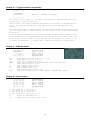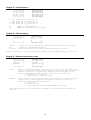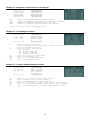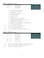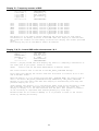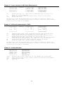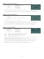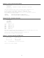
1
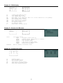
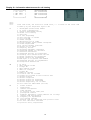
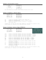
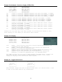
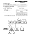
Nokia
NetMonitor
Manual
Version 0.95
11.11.2002
Document keeper
Base document
PDF + Enhancements to base document
Graphics
:
:
:
:
nobbi ([email protected])
Flipo ([email protected])
nobbi
nobbi
Phone Models and Software versions
Notes for 21xx / 31xx / 81xx phones
The older phones netmonitor has some differences when compared with the one of newer models, but
this manual can be used as a guide, because the overall working method and the display contents are
very similar in most cases.
Notes for 51xx/61xx/62xx/71xx/88xx/91xx/32xx and other phones
This document covers the majority of pages from these phones netmonitor. Some of them may have
little differences, like missing/additional pages, different info, etc.
The 51xx and 61xx pages are almost identical, there are a few pages concerning multiband information
in 6150 which are different in the singleband phones, and the xx90 pages are partially different, because
of some special things in GSM1900.
The 32xx has some more pages, which are not very well documented yet.
The 62xx and 71xx have a whole bunch of pages concerning W@P and the large internal flash memory.
These are not documented yet. If you have any clue about theses pages, send me a mail.
The 91xx pages are almost identical to the 6110 ones, with few additional pages.
The goal right now is to make an accessible manual, that will get better over the time. Please contribute
with all the info that you find relevant. Please note that this manual does only deal with pages which are
of known content, so if a page is not mentioned here, I have most likely no knowledge about the
meaning of the page.
Used Information Sources :
[1]
Netmonitor description (RD843.txt) from Nokia Mobile Phones
[2]
Marcin Wiaceks homepage (http://marcin-wiacek.topnet.pl/)
[3]
Researches from Nobbi & various other people
2
Menu Modes
There are three Menu Display modes:
-
the execute mode
the data display mode
the help mode
Different modes are marked in this manual as follows:
**************
*
*
*
Execute *
*
Mode
*
*
*
**************
++++++++++++++
+
+
+Data display+
+
Mode
+
+
+
++++++++++++++
##############
#
#
#
Help
#
#
Mode
#
#
#
##############
The execute mode is entered from the menu by selecting a menu directly with his number. If the test
index entered pertains to a test that resets a timer (test 80) for example, then the timer is reset as soon
as the OK button has been pressed in the menu, and the data display mode takes over. In other words,
the execute mode is of the one-shot type. To run another test in the execute mode, the Field Test
Display menu must be reactivated.
So, be very careful when jumping to a netmonitor page directly from the menu selection. You may
activate the execute mode incidentally, causing your phone to behave not as expected.
The data display mode is active by default when the Netmonitor is active. During data display mode, the
field test data is visible on the main display.
During help mode, one screen of instructions is shown for each test to make it easier to identify the test
in question. A long press of the asterisk (*) is used to toggle between these two modes.
The arrow keys (^,v) offer an easy way to switch to another test without using the menu. However,
nothing will be executed or set on although such tests would be passed. This is to prevent the user from
accidentally clearing any valuable data. The help mode is also a non-execute mode. Display numbers
have been selected in such way that no 5-terminated test number is an execute display.
Reserving SIM phonebook locations
When using a phone with enabled field test displays, it is highly recommended to put some default data
into the SIM phonebook locations that are used by some field test displays. Especially Test 17 (BTS
TEST) may give some confusing results if SIM phonebook location 33 is not correctly configured.
Additionally, this prevents accidental storing of phone numbers and names into such locations.
Displays 52 and 53 may also write some data to the SIM phonebook locations 35 and 36.
Location
31
32
33
34,35,36
Default
65535
65535
0
34,35,36
Data Used by Display #
71
72
17 (BTS TEST)
52, 53
Reserving SIM SCM locations is not necessary if the user is sure that he will never select these displays
using menu shortcut (which executes the display in question).
3
Table of contents
Phone Models and Software versions ..................................................................................... 2
Notes for 21xx / 31xx / 81xx phones...................................................................... 2
Notes for 51xx/61xx/62xx/71xx/88xx/91xx/32xx and other phones....................... 2
Menu Modes ............................................................................................................................ 3
Reserving SIM phonebook locations ....................................................................................... 3
Table of contents ..................................................................................................................... 4
Basics: Channel numbers in GSM........................................................................................... 4
Display 1 – Serving cell info..................................................................................................... 5
Display 10 – Paging Repetition Period, TMSI, Location Update Timer, AFC and AGC ......... 9
Display 20 – Charging state................................................................................................... 12
Display 39 – Information about reasons for call clearing....................................................... 16
Display 40 – Reset handover counters.................................................................................. 17
Display 60 – Reset counters to zero...................................................................................... 21
Display 65 – SMS attempts counters .................................................................................... 23
Display 70 – Temporary counters of DSP ............................................................................. 24
Display 80 – Reset and restart timers ................................................................................... 28
Display 100 (7110, 62XX) – Internal memory usage, overview ............................................ 31
Display 240 (no output) – Clear counters and start timers .................................................... 34
Basics: Channel numbers in GSM
GSM uses channel numbers between 0 and 1023. These frequency channels are allocated
by the different types of GSM as follows:
Type:
Subtype:
Channels:
GSM400
GSM450
GSM480
GSM750
GSM850
PGSM
EGSM
259
306
438
128
1
0
975
0
955
512
512
GSM700
GSM850
GSM900
GSM-R
GSM1800
GSM1900
GSM1800
GSM1900
.. 293
.. 340
.. 511
.. 251
.. 124
.. 124
.. 1023
.. 124
.. 1023
.. 885
.. 810
4
Display 1 – Serving cell info
++++++++++++++
+abbb ccc ddd+
+ e ff g mmmm+
+ nnn
ppp+
+
oooo
+
++++++++++++++
a
bbb
ccc
ddd
e
ff
g
mmmm
nnn
oooo
ppp
##############
#CH RxL TxPwr#
#TS TA RQ RLT#
# C1
C2 #
#
CHT
#
##############
H, if carrier numbers are scrolled when hopping is on. Otherwise ' '.
When mobile is on a TCH :
DCH carrier number in decimal.
When mobile is NOT on a TCH :
CH means carrier number in decimal.
If hopping is on, used channels are scrolled when display is updated.
rx level in dBm, minus sign is not shown if <=-100
tx power level. If transmitter is on, symbol * is shown in front of the
power level value.
Time Slot, range is 0 - 7
Timing advance, range is 0 – 63
RX quality (sub), range is 0 - 7
Radio Link Timeout value. If value is negative, 0 is shown.
Maximum value is 64. When mobile is NOT on TCH then xx is shown.
value of the path loss criterium (C1). Range is -99 - 999.
type of current channel (TCH := Traffic Channel):
THR0 : TCH HalfRate (HR) subchannel 0
THR1 : TCH HR subchannel 1
TFR : TCH FullRate (FR)
TEFR : TCH EnhancedFullRate
F144 : TCH FR data channel, speed 14.4 kbps
F96 : TCH FR data channel, speed 9.6 kbps
F72 : TCH FR data channel, speed 7.2 kbps
F48 : TCH FR data channel, speed 4.8 kbps
F24 : TCH FR data channel, speed 2.4 kbps
H480 : TCH HR data channel, speed 4.8 kbps, subch 0
H481 : TCH HR data channel, speed 4.8 kbps, subch 1
H240 : TCH HR data channel, speed 2.4 kbps, subch 0
H241 : TCH HR data channel, speed 2.4 kbps, subch 1
FA
: TCH FR signalling only (FACCH) channel
FAH0 : TCH HR signalling only (FACCH) channel, subch 0
FAH1 : TCH HR signalling only (FACCH) channel, subch 1
SDCC : SDCCH
AGCH : Access Grant CHannel
CCCH : one of the Common Control CHannels
CBCH : CCCH and cell broadcast receiving on
BCCH : Broadcast Control CHannel
SEAR : SEARCHing for available networks
NSPS : MS is in ’No Service, Power Save’ state
value of the cell reselection criterium (C2).
Range is -99 to 999. If phone is phase 1 then C1 value is shown.
5
Display 2 – More info about serving cell
++++++++++++++
+ aa b c Bdd +
+ ee f
+
+ ggg hh iii +
+ H=j mm nn +
++++++++++++++
aa
##############
#PM RAR Ro BC#
#RelR QLF
#
#CRO TO PenT #
#H MAIO HSN #
##############
paging mode
NO : normal paging
EX : extended paging
RO : paging reorganization
SB : same as before
maximum number of Random Access retransmission
roaming indicator, values are 'R' or ' '.
Letter B and BSIC value, range is 0 - 63.
Reason of last call release (See Display 39, CC cause codes)
RX quality (full), range is 0 - 7
Cell reselection offset, range 0 - 126 dB.
[0 .. 63] * 2 dB. 'xxx' in dedicated mode.
Temporary offset, range 0 - 60 dB.
[0 .. 7] * 10 dB. 70 dB means infinite time.
'xx' in dedicated mode.
Penalty time, range 0 - 620 s.
[0 .. 31] * 20 s. 'xxx' in dedicated mode.
Hopping channel
0
Single RF channel
1
RF hopping channel
mobile allocation index offset, MAIO
Range: 00 to 63 / xx when H=0
hopping sequence number, HSN
Range: 00 to 63 / xx when H=0
b
c
Bdd
ee
f
ggg
hh
iii
j
mm
nn
Display 3 – Serving cell, 1st and 2nd neighbour
++++++++++++++
+aaabbbcccddd+
+aaabbbcccddd+
+aaabbbcccddd+
+
ef gh
+
++++++++++++++
1.
2.
3.
4.
4.
row:
row:
row:
row,
row,
aaa
bbb
ccc
ddd
e,g
f,h
##############
#SCH C1 rx C2#
#1CH C1 rx C2#
#2CH C1 rx C2#
#
1N 2N
#
##############
serving cell information
1. neighbour information
2. neighbour information
ef: 1. neighbour information
gh: 2. neighbour information
carrier number in decimal, EGSM channels are displayed as Eaa
idle mode : C1 value, range is -99 - 999
ded. Mode : 'B' and BSIC value
RX level in dBm, minus sign is not shown if <=-100
C2 value, range is -99 - 999
F : cell is in a forbidden location area
B : cell is barred
N : cell is normal priority
L : cell is low priority
6
Display 4 & 5 – 3rd to 8th neighbour cell
++++++++++++++
+aaabbbcccddd+
+aaabbbcccddd+
+aaabbbcccddd+
+ ef gh ij +
++++++++++++++
1.
2.
3.
4.
4.
4.
row:
row:
row:
row,
row,
row,
##############
#3CH C1 rx C2#
#4CH C1 rx C2#
#5CH C1 rx C2#
# 3N 4N 5N #
##############
3./6. neighbour information
4./7. neighbour information
5./8. neighbour information
ef: 3./6. neighbour information
gh: 4./7. neighbour information
ij: 5./8. neighbour information
aaa
bbb
carrier number in decimal, EGSM channels are displayed as Eaa
idle mode : C1 value, range is -99 - 999
ded. Mode : 'B' and BSIC value
rx level in dBm, minus sign is not shown if <=-100
C2 value, range is -99 - 999
F : cell is in a forbidden location area
B : cell is barred
N : cell is normal priority
L : cell is low priority
ccc
ddd
e,g,i
f,h,j
Display 6 – Network selection display
++++++++++++++
+aaabb aaabb+
+aaabb aaabb+
+aaabb aaabb+
+aaabb aaabb+
++++++++++++++
##############
#LReg
1_For#
#1_Pre 2_For#
#2_Pre 3_For#
#3_Pre 4_For#
##############
This display shows the last registered networks country code (MCC) and
network code (MNC) as well as the codes for four forbidden networks
and the first 3 preferred networks.
If a three-digit MNC is used (GSM1900), display looks different:
++++++++++++++
+aaabbbaaabbb+
+aaabbbaaabbb+
+aaabbbaaabbb+
+aaabbbaaabbb+
++++++++++++++
1.
2.
3.
4.
row:
row:
row:
row:
aaa
bbb
last registered network
1st preferred network
2nd preferred network
3rd preferred network
-
1st
2nd
3rd
4th
forbidden
forbidden
forbidden
forbidden
network
network
network
network
country code coded in BCD
network code coded in BCD, third digit can be 'F'
7
Display 7 – System information bits for serving cell
++++++++++++++
+E A H C I BR+
+a b c d e fg+
+ECSC 2Ter MB+
+ h
i
j+
++++++++++++++
a
b
c
d
e
f
g
1
1
1
1
1
1
1
is
is
is
is
is
is
is
shown
shown
shown
shown
shown
shown
shown
##############
#Serving Cell#
#System Info #
#Bits
#
#
#
##############
if
if
if
if
if
if
if
emergency calls are supported
attach-detach-procedure is allowed
half rate channels are supported
C2 values are broadcasted
system information 7 and 8 are broadcasted
cell broadcast is supported
re-establishment is supported
The following items are used only in dualband phones:
h
In idle mode 1 is shown if Early Classmark (ECSC) sending is supported.
In dedicated mode (conversation) X is shown.
i
In idle mode 1 is shown if 2Ter messages are supported.
In dedicated mode (conversation) X is shown.
j
MultiBand reporting decimal value (0,1,2,3) is shown if supported.
This is shown both in idle and dedicated mode.
The following is picked from Phase2+ ETSI ETS 300578 (TS GSM 05.08), Section 8.4.3
"Additional cell reporting requirements for multi band MS".
For a multi band MS the number of cells, for each frequency band supported, which
shall be included in the measurement report is indicated by the parameter,
MULTIBAND_REPORTING. The meaning of different values of the parameter is specified as
follows:
Value
Meaning
00 (0)
Normal reporting of the six strongest cells, with known and allowed NCC part
of BSIC, irrespective of the band used.
01 (1)
The MS shall report the strongest cell, with known and allowed NCC part of
BSIC, in each of the frequency bands in the BA list, excluding the frequency
band of the serving cell. The remaining positions in the measurement report
shall be used for reporting of cells in the band of the serving cell. If
there are still remaining positions, these shall be used to report the next
strongest identified cells in the other bands irrespective of the band used.
10 (2)
The MS shall report the two strongest cells, with known and allowed NCC part
of BSIC, in each of the frequency bands in the BA list, excluding the
frequency band of the serving cell. The remaining positions in the
measurement report shall be used for reporting of cells in the band of the
serving cell. If there are still remaining positions, these shall be used to
report the next strongest identified cells in the other bands irrespective
of the band used.
11 (3)
The MS shall report the three strongest cells, with known and allowed NCC
part of BSIC, in each of the frequency bands in the BA list, excluding the
frequency band of the serving cell. The remaining positions in the
measurement report shall be used for reporting of cells in the band of the
serving cell. If there are still remaining positions, these shall be used to
report the next strongest identified cells in the other bands irrespective
of the band used.
8
Display 10 – Paging Repetition Period, TMSI, Location Update Timer, AFC and AGC
++++++++++++++
+TMSIaaaaaaaa+
+T321:bbb/ccc+
+PRP:d ee ff+
+ ggggg hhh +
++++++++++++++
aaaaaaaa
bbb
ccc
d
ee
ff
ggggg
hhh
##############
#TMSI(hex)
#
#T3212ctr/tim#
#PaRP DSF AGC#
# AFC
Ch #
##############
last assigned TMSI value in hex format
Current value of T3212 counter (range is 000 - 'ccc'), where 1 means 6 min
time. So, if this value is 2 less than 'ccc' then next periodic location
updating will be made within 2 * 6 min = 12 minutes.
Timeout value of T3212 counter (range is 000 - 240, where 1 means 6 min
time between location updates and 240 means 240 * 6 min = 24 h between
location updates. 000 means that a periodic location update will not
occur) This value is received from the network.
Value of paging repetition period (range is 2 – 9, which means paging will
be in every Xth multiframe. When paging is in every second multiframe,
mobile takes more current than if it were in every 9th multiframe)
Downlink signalling failure value. If value is negative, 0 is shown.
Maximum value is 45. When mobile is on TCH then xx is shown.
Gain value on TCH/SDCCH, range is 0 - 93
VCTCXO AFC DAC control, range is -1024 - 1023
Serving cell channel number
Display 11 – Network parameters
++++++++++++++
+CC:aaa NCbbb+
+ LAC:ccccc +
+ CH : dddd +
+ CID:eeeee +
++++++++++++++
aaa
bbb
ccccc
dddd
eeeee
##############
# MCC
MNC #
#LocAreaCode #
#ServChannel #
#
CellId
#
##############
MCC value in decimal (MCC=Mobile Country Code)
MNC value in decimal (MNC=Mobile Network Code)
Three digits are shown only in GSM1900.
Two digits are shown in GSM900 and GSM1800.
LAC value in decimal (in older SW-versions this value is in hexadecimal)
Serving cell channel number
Cell Identifier in decimal (in older SW-versions this value is in
hexadecimal)
Display 12 – Ciphering, hopping, DTX Status and IMSI
++++++++++++++
+CIPHER :aaa +
+HOPPING:bbb +
+DTX
:ccc +
+IMSI
:ddd +
++++++++++++++
aaa
bbb
ccc
ddd
##############
#CipherValue #
#HoppingValue#
#DTXValue
#
#IMSIAttach #
##############
ciphering value, OFF/A51/A52
hopping value, ON/OFF
DTX value ON/OFF
IMSI attach
ON : IMSI attach on
OFF : IMSI attach off
These values are updated only on when the phone is active on a TCH.
9
Display 13 – Uplink DTX switching display
**************
*aaaaaaaaaa *
*DTX(DEF):bbb*
*DTX(BS) :ccc*
*
*
**************
##############
#DTXMode
#
#DefaulDTXSta#
#DTXValFromBS#
#
#
##############
With this display it is possible to see whether the MS uses DTX or not.
This display must be activated from MENU to change DTX state. When MENU is not active
and the user is scrolling field test displays with NEXT and PREVIOUS, the DTX state
will not be changed.
aaaaaaaaaa
bbb
ccc
status of switched mode.
DTX:ON
: MS uses DTX
DTX:OFF
: MS does not use DTX
DTX:DEF
: MS use default state of DTX
NOTALLOWED: BS does not allow MS to decide if it uses
DTX or not.
default state of DTX in MS. The value is either ON or OFF
is DTX value from BS
MAY : BS allows MS to decide if it uses uplink DTX or not
USE : BS controls MS to use DTX (on uplink)
NOT : BS controls MS not to use DTX (on uplink)
Display 14 – Toggle Screening Indicator
**************
* SCREENING *
* INDICATOR *
*
IS XX
*
*
*
**************
XX : 00 or 01
##############
#Use menu to #
# change
#
# Screening #
# indicator #
##############
When selected, changes the value of the Screening Indicator from 0 to 1 and vice
versa.
10
Display 17 – Switch 'BTS Test' Status
**************
*
*
* BTS TEST *
*
ON
*
*
*
**************
**************
*
*
* BTS TEST *
*
OFF
*
*
*
**************
##############
#Use menu to #
#toggle BTS #
#test ON/OFF #
#
#
##############
This display is used to toggle the BTS_TEST flag in EEPROM. If BTS_TEST is set then
each time the mobile sends a search list it uses only the carrier number stored on
SIM phonebook location 33. Also the neighbour information from system information
messages is ignored. If the BTS_TEST flag is not set, then the value of SIM phonebook
location 33 is ignored and the mobile behaves normally (i.e. does neighbour
measurements according to GSM specifications).
To activate BTS TEST perform the following steps:
Save desired channel number in SIM phonebook location 33
Select display 17 in execute mode
Switch power off and on OR force a cell reselection
If activation succeeded, you will read "BTS TEST ON" in display 17. The 6210 will
show "BTS TEST REQUESTED" instead.
To deactivate BTS tests either select display 17 in execute mode or save a number in
SIM phonebook location 33 which does NOT represent a valid carrier number, then
switch power off and on OR force a cell reselection
CAUTION! The display does not show the value of the BTS_TEST flag in EEPROM. Although
the value is set, BTS_TEST can show to be off. If there is no legal carrier number in
SIM phonebook location 33 (GSM900: 1-124, GSM1800: 512-885, EGSM: 0, 975-1023) the
display shows that BTS_TEST is off. Also if the mobile was already registered to some
carrier before switching BTS_TEST status, the display can show a different value from
the one in EEPROM.
Display 18 – Lights status control
Forces keyboard and display lights on/off while displaying any netmonitor screen. The
light will not remain on after leaving netmonitor
**************
*
*
*
LIGHTS
*
*
ON
*
*
*
**************
**************
*
*
*
LIGHTS
*
*
OFF
*
*
*
**************
##############
#Use menu to #
# toggle
#
# lights
#
# ON/OFF
#
##############
Display 19 – Toggle Cell Barred Status
**************
*
*
* CELL BARR *
* ACCEPTED
*
*
*
**************
**************
*
*
* CELL BARR *
* REVERSE
*
*
*
**************
**************
*
*
* CELL BARR *
* DISCARD
*
*
*
**************
##############
#Use menu to #
#toggle cell #
#barr status #
#DIS/ACC/REV #
##############
This test is meant to be used when some cells are tested before taking them into
commercial use. By setting the CELL_BARRED to on in the base station normal GSM
phones will not try to camp on these barred cells.
By selecting CELL BARR REVERSE, the MS will only use the cells which have CELL_BARRED
set.
By selecting CELL BARR DISCARD, the MS will use all cells, irrespective wether
CELL_BARRED is set or not.
NOTE: If a cell has been selected before barring state in phone is changed the
selected cell will remain the current cell. After the next cell reselection the cell
barring state is working as expected.
11
Display 20 – Charging state
**************
* aaa bbbbb *
* Tccc dddd *
* Ceee Wfff *
* gggg hhhh *
**************
##############
#BatVol ChMod#
#Btemp ChTime#
#ChrgVol Pwm #
# Btyp BFDC #
##############
aaa
Battery voltage in decimal, range is 0.00 - 9.99 V, decimal point is not
shown; e.g. 7.19 V is shown as 719 on the display
bbbbb
Charging mode 5 digit symbol:
xxxxx : Charger not connected or charging disabled.
BatCk : Battery testing is going.
BSIFa : Charging off because of battery BSI measurement failed.
CelBr : Charging off because one or more cells broken inside
battery.
ChaCk : EM is checking charger.
Charg : Charging.
ColdC : Cold charging.
ColdM : Battery cold and maintenance going.
CurFa : Charging off because charger current measurement failed.
DisCh : Battery discharging going.
F_Che : Fast charging checks.
Faile : Failure.
FastC : Fast charging going.
FullM : Battery full and maintenance going.
HotM : Battery hot and maintenance going.
I_Che : Init checks.
InitC : EM charging is being initialized.
L_Che : Li charging checks.
LiAFu : PWM level is below the battery full limit.
LiDCH : Li-ion DCH charging.
LiFul : PWM has been below the battey full limit for a certain time
that is specified for full battery.
LiHot : Li-ion hot charging.
LithC : Charging of Lithium-ion battery.
LiTxO : TX on and Li charging going.
LNFTx : TX on, Li charging going and battery is not full anymore.
M_Che : Maintenace charging checks.
MaBFD : Maintenace BFD charging.
Maint : Maintenance charging.
TmpFa : Charging off because of battery NTC measurement failed.
TxNoF : TX on, Ni charging going and battery is not full anymore.
TxOnC : TX on and Ni charging going.
VolFa : Charging off because charger voltage measurement failed.
ccc
ddd
Battery temperature in centigrade, from -30 to +90.
Charging time. Format is HMM. Timer is automatically reset and started when
charger is connected and stopped when battery is full or charger is
disconnected.
Charger voltage in decimal, range is 0.0 - 18.7 V, decimal point is not shown.
Charge control output, decimal, range is 000 - 255.
Lithium battery type (BSI value multiplied by 4), or NiMH battery size.
Battery full delay counter. When battery is getting full and charging current
is less than predefined limit, this timer will be started. If timer reaches 0,
charging will be stopped.
eee
fff
gggg
hhhh
12
Display 21 – Constant voltage charging display
**************
* aaaa bbbb *
* cccc dddd *
* eeee ffff *
*
*
**************
aaaa
bbbb
ccc
ddd
eee
fff
##############
#MTDif MPDif #
#BupV BDownV#
#AverV SumMF #
#
#
##############
Difference between measured voltage and goal voltage, decimal point is not
shown.
Difference between measured voltage and result of previous measurement
(basically same as using change of error), decimal point is not shown.
Battery up voltage (highest measured voltage), maximum ripple voltage.
Battery down voltage (lowest measured voltage), minimum ripple voltage.
Average measured voltage.
Sum of membership function sets beliefs, range 0.00-9.99, decimal point is
not shown; e.g. 1.53 is shown as 153. If sum of 1.00 is reached then battery
full indication is shown.
Display 22 – Battery full detection
**************
* Eaaa Cbbb *
* Dccc Rddd *
* Ieee Afff *
* Tggg hhhh *
**************
##############
#DeriC ChAm #
# VDif VDrop #
# VDTi AvDif #
# Temp Volt #
##############
Letters E, C, D, R, I, A, T and V are displayed if values are shorter than 4 digits.
Eaaa
DerivCount membership function set, range 0.00-1.00, decimal point is not
shown; e.g. 0.23 is shown as 023.
Cbbb
ChargeAmount membership function set, range 0.00-1.00, decimal point is not
shown; e.g. 0.23 is shown as 023.
Dccc
VolDiffToMax membership function set, range 0.00-1.00, decimal point is not
shown; e.g. 0.23 is shown as 023.
Rddd
VolDropCnt membership function set, range 0.00-1.00, decimal point is not
shown; e.g. 0.23 is shown as 023.
Ieee
VolDiffTime membership function set, range 0.00-1.00, decimal point is not
shown; e.g. 0.23 is shown as 023.
Afff
AverDiff membership function set, range 0.00-1.00, decimal point is not
shown; e.g. 0.23 is shown as 023.
Tggg
Temperature membership function set, range 0.00-1.00, decimal point is not
shown; e.g. 0.23 is shown as 023.
Vhhh
Voltage membership function set, range 0.00-1.00, decimal point is not
shown; e.g. 0.23 is shown as 023.
13
Display 23 – Battery and phone state monitor
**************
* aaaa bbbb *
* cccc dddd *
*eee fff gggg*
*hhh iiiijjjj*
**************
aaaa
bbbb
cccc
dddd
eee
fff
gggg
hhh
iiii
jjjj
##############
#TxOn
TxOff#
#ChCur Stdby#
#Age CAP Curr#
#Tmp CmAhTarg#
##############
TXon voltage (expected voltage with transmitter switched on), decimal point
not shown (a.aaa mV)
TXoff voltage (expected voltage with transmitter switched off), decimal
point not shown (b.bbb mV)
charging current, decimal point not shown (c.ccc mA)
predicted standby level (expected voltage in standby mode), decimal point
not shown (d.ddd mV)
estimated age for Li-ion battery (0:new to 100:old). NiMH always shows 33
battery's percentage level (0,25,50,100)
current consumption indicated by PSM (0.1 mA)
battery's temperature (C) (Only for Li battery)
charged capacity (mAh) into battery
tells what is the next capacity target (mAh) to reach for next battery bar
level to be displayed
Display 24 – BSI values
**************
* aaaa bbbb *
*
cccc *
*
dddd *
* eeee ffff *
**************
aaaa
bbbb
cccc
dddd
eeee
ffff
##############
#V_inst V_avg#
#BSI value
#
#Elapsed time#
#RST_m RST_h#
##############
BSI (Battery Size Indicator) value
minutes elapsed since charger was disconnected or phone was switched on
Display 30 – Audio API register display
**************
* aaaa bbbb *
* cccc dddd *
* eeee ffff *
* gggg hhhh *
**************
aaaa
bbbb
cccc
dddd
eeee
ffff
gggg
hhhh
##############
#A1Cnf A2Cnf#
# ST
AU3 #
#1Tone 2Tone#
# Conf HFVol#
##############
API_AUD1_CTRL
API_AUD2_CTRL
API_SIDETONE
API_AU3
API_1_TONE (first frequency of DTMF generator)
API_2_TONE (first frequency of DTMF generator)
API_CONFIG
API_HF_VOL (Volume setting for Audio output)
14
Display 34 – FBUS display
**************
*aabbccdd
*
*eeefff - ggg*
*hhh iii jjj *
*k-*
**************
aa
bb
cc
dd
eee
fff
ggg
hhh
iii
jjj
k
##############
#CM LD LM NM #
#PEC FEC OEC #
#ACC RXS TXS #
#Mod
#
##############
current fbus media in hex
last sender dev in hex
last sender media in hex
Next media to be connected. Same as aa if the connection is not pending.
fbus parity error counter
fbus framing error counter
fbus overrun error counter
fbus alive check counter
RX Sequence number
TX Sequence number
Phone mode: S=slave, H=host
Display 35 – Reasons for SW resets
**************
*aaaaa
*
*bbbbbbbb
*
*
*
*
*
**************
aaaaa
bbbbbbbb
##############
#Reset reason#
#Task name
#
#
#
#
#
##############
last reset reason.
NORM
: Probably normal power up.
UNKNO
: Default value, reset reason is unknown.
HW WD
: ASIC watchdog timeout.
SWDSP
: DSP recovery reset
SWSIM
: SIM contact failure reset
SWIDL
: Idle task not running reset
STACK
: Task stack overflow
Name of running task before reset.
Display 36 – Counters for resets
++++++++++++++
+ aa bb cc +
+ dd ee ff +
+
+
+
+
++++++++++++++
aa
bb
cc
dd
ee
ff
Unknown resets
ASIC watchdog resets
DSP recovery resets
SIM contact failure resets
Idle task not running resets
Task stack overflow resets
15
Display 39 – Information about reasons for call clearing
++++++++++++++
+ CC: aaaa
+
+ MM: bbbb
+
+ RR: cccc
+
+
+
++++++++++++++
aaaa,
bbbb,
cccc
##############
#CC CauseValu#
#MM CauseValu#
#RR CauseValu#
#
#
##############
cause code value, see section 10.5/GSM 04.08, '*' is shown if the cause code
is made up by the respective layer in MS
CC
1
3
8
16
17
18
19
21
22
27
28
31
34
38
41
42
44
47
50
55
57
65
68
69
88
unassigned (unallocated) number
no route to destination
operator determined barring
normal call clearing
user busy
no user responding
user alerting, no answer
call rejected
number changed
destination out of order
invalid number format/number incomplete
normal/unspecified
no circuit/channel available
network out of order
temporary failure
switching equipment congestion
requested channel not available
ressource unavailable
requested facility not subscribed
Incoming calls barred within the CUG
bearer capability not authorized
bearer service not implemented
ACM equal to or greater than ACMmax
requested facility not implemented
incompatible destination
MM
0
2
3
4
5
6
11
12
13
17
22
32
33
34
38
no error
IMSI unknown in HLR
illegal MS
IMSI unknown in VLR
IMEI not accepted
illegal ME
PLMN not allowed
location area not allowed
roaming not allowed in this location area
network failure
network congestion
service option not supported
service option not subscribed
service temporarily out of order
call cannot be identified (call RE)
RR
0
1
2
3
4
5
8
9
10
65
97
101
111
normal release
unspecified
channel unacceptable
timer expired
no activity on the radio path
pre-emptive release
handover impossible, timing advance out of range
channel mode unacceptable
frequency not implemented
call already cleared
message type not compatible with protocol state
no cell allocation available
protocol error, unspecified
16
Display 40 – Reset handover counters
**************
*
RESET
*
* HANDOVER *
* COUNTERS *
*
*
**************
##############
# Use menu #
# to reset #
# handover #
# counters #
##############
With this display all counters of the handover displays can be reset.
Display 41 (singleband) – Handover display
++++++++++++++
+HandOOK: aaa+
+PrevCh : bbb+
+HONotOK: ccc+
+HOIntra: ddd+
++++++++++++++
aaa
bbb
ccc
ddd
##############
#HandOvOKCntr#
#PrevChanCntr#
#HandOvNOKCnt#
#HOIntraOKCnt#
##############
counter for successful handovers (max. amount 999)
counter for successful back to previous channel attempts
counter for failed handovers
counter for successful intracell handovers or assignments
(max. amount 999)
Counters will stop when they reach their maximum. To initialize the counters to zero,
select display 40. Display 60 also initializes these counters.
Display 41 (dualband) – Handover display, INTER CELL
++++++++++++++
+ aaaa bbbb +
+ cccc dddd +
+eeefffggghhh+
+iiijjjkkklll+
++++++++++++++
##############
#G>G InterD>D#
#G>D OK D>G#
#InterHoFail #
# BackToPrev #
##############
aaaa
bbbb
cccc
dddd
counter
counter
counter
counter
of
of
of
of
eee
fff
ggg
hhh
counter
counter
counter
counter
for
for
for
for
iii
counter of successful back
from GSM900 to GSM900
counter of successful back
from GSM1800 to GSM1800
counter of successful back
from GSM900 to GSM1800
counter of successful back
from GSM1800 to GSM900
jjj
kkk
lll
successful
successful
successful
successful
failed
failed
failed
failed
handovers
handovers
handovers
handovers
handovers
handovers
handovers
handovers
(max
(max
(max
(max
(max
(max
(max
(max
9999)
9999)
9999)
9999)
999)
999)
999)
999)
from
from
from
from
from
from
from
from
GSM900
GSM1800
GSM900
GSM1800
GSM900
GSM1800
GSM900
GSM1800
to
to
to
to
to
to
to
to
GSM900
GSM1800
GSM1800
GSM900
GSM900
GSM1800
GSM1800
GSM900
to previous channel attempts (max 999)
to previous channel attempts (max 999)
to previous channel attempts (max 999)
to previous channel attempts (max 999)
Counters will stop when they reach their maximum. To initialize the counters to zero,
select display 40. Display 60 also initializes these counters.
17
Display 42 (dualband) – Handover display, INTRA CELL
++++++++++++++
+ aaaa bbbb +
+ cccc dddd +
+eeefffggghhh+
+iiijjjkkklll+
++++++++++++++
##############
#G>G IntraD>D#
#G>D OK D>G#
#IntraHoFail #
# BackToPrev #
##############
aaa
bbb
ccc
ddd
counter
counter
counter
counter
of
of
of
of
successful
successful
successful
successful
eee
fff
ggg
hhh
counter
counter
counter
counter
of
of
of
of
failed
failed
failed
failed
iii
counter of successful back to previous
(max 999) from GSM900 to GSM900
counter of successful back to previous
(max 999) from GSM1800 to GSM1800
counter of successful back to previous
(max 999) from GSM900 to GSM1800
counter of successful back to previous
(max 999) from GSM1800 to GSM900
jjj
kkk
lll
INTRACELL
INTRACELL
INTRACELL
INTRACELL
INTRACELL
INTRACELL
INTRACELL
INTRACELL
handovers
handovers
handovers
handovers
handovers
handovers
handovers
handovers
(max
(max
(max
(max
(max
(max
(max
(max
9999)
9999)
9999)
9999)
999)
999)
999)
999)
from
from
from
from
from
from
from
from
GSM900
GSM1800
GSM900
GSM1800
GSM900
GSM1800
GSM900
GSM1800
to
to
to
to
to
to
to
to
GSM900
GSM1800
GSM1800
GSM900
GSM900
GSM1800
GSM1800
GSM900
normal INTRA CELL channel attempts
normal INTRA CELL channel attempts
normal INTRA CELL channel attempts
normal INTRA CELL channel attempts
Counters will stop when they reach their maximum. To initialize the counters to zero,
select display 40. Also display 60 initializes these counters.
Display 43 L2 display
++++++++++++++
+T200MS :aaaa+
+T200BS :bbbb+
+T200MS :cccc+
+T200BS :dddd+
++++++++++++++
aaaa
bbbb
cccc
dddd
##############
#T200 MS GSM #
#T200 BS GSM #
#T200 MS DCS #
#T200 BS DCS #
##############
GSM900 : counts how many times T200 in MS has expired and therefore a L2
transmission has been repeated.
GSM900 : counts how many times T200 in BS (network) has expired and
therefore a L2 frame was requested again.
GSM1800: counts how many times T200 in MS has expired and therefore a L2
transmission has been repeated. (for dualband phones)
GSM1800: counts how many times T200 in BS (network) has expired and
therefore a L2 frame was requested again. (for dualband phones)
The GSM900 counters are also valid in GSM900/GSM1800 multiband phones. Counters will
stop when they reach their maximum. To initialize the counters to zero, select
display 40. Display 60 also initializes these counters.
Display 44 – Toggle revision level
**************
*
*
* REVISION
*
*LEVEL IS 00 *
*
*
**************
**************
*
*
* REVISION
*
*LEVEL IS 01 *
*
*
**************
When selected, changes the value of Revision Level from 0 to 1 and vice versa. I have
no idea if this makes sense in any circumstances.
18
Display 45 – Toggle transmitter functionality
**************
*
*
*TRANSMITTER *
* XXXXXXXX *
*
*
**************
XXXXXXXX
ENABLED or DISABLED
This display has no effect in 7110 phone, irrespective of the displayed status the
transmitter is always switched on.
When selected, this display disables transmitter functionality if enabled and vice
versa. New setting is valid until next power off or until new execute of this
display.
This FTD can be used to simulate easily situations when the MS can hear the network
(i.e. receiving signal is good enough), but the network can not receive any messages
from the MS.
Location updating attempts or MO call establishment attempts can be failed (random
access failure) by this FTD and field testing of these failures is much easier now.
Next periodic location updating can be checked from the display 10 (chapter 3.1.10)
by taking the difference of current T3212 counter value and T3212 timeout value.
Display 51 – SIM information
++++++++++++++
+aaa bbb ccc +
+ dddddddd
+
+ f g hh ii +
+ j
kkkk +
++++++++++++++
aaa
bbb
ccc
dddd
f
g
hh
ii
j
kkkk
##############
#VSel Bau SAl#
#SCond CStop#
#PIN12 PUK12#
# ATR FE/PE #
##############
SIM voltage selection type (5, 3 or 3/5)
SIM baudrate (372, 64, 32 or 0)
Clock stop allowed, Yes or No
Clock stop condition, Up/Down/xxxxxxxx if no preferred level
PIN1 attempts left (0,1,2,3)
PIN2 attempts left (0,1,2,3)
PUK1 attempts left (0-10)
PUK2 attempts left (0-10)
ATR retransmission counter (0-9)
Transmission frame/parity errors, FE/PE + hexadecimal count
Display 54 – Block display 1
++++++++++++++
+aa bb aa bb+
+aa bb aa bb+
+aa bb aa bb+
+aa bb aa bb+
++++++++++++++
1.
2.
3.
4.
aa
bb
row:
row:
row:
row:
Block
Block
Block
Block
set
set
set
set
1,
3,
5,
7,
##############
#ResF1 ResF2#
#ResF3 ResF4#
#ResF5 ResF6#
#ResF7 ResF8#
##############
block
block
block
block
set
set
set
set
2
4
6
8
Number of reserved blocks
Number of free blocks in worst case
19
Display 55 – Block display 2
++++++++++++++
+aa bb aa bb+
+aa bb aa bb+
+aa bb aa bb+
+aa bb aa bb+
++++++++++++++
1.
2.
3.
4.
row:
row:
row:
row:
Block
Block
Block
Block
aa
bb
set
set
set
set
##############
#ResF9 ResF10#
#ResF11ResF12#
#ResF13ResF14#
#ResF15ResF16#
##############
9, block set 10
11, block set 12
13, block set 14
15, block set 16
Number of reserved blocks
Number of free blocks in worst case
Display 56 – Block display 3
++++++++++++++
+ aaaaaa bbb +
+ cccccccc
+
+
+
+
+
++++++++++++++
aaaaaa
bbb
cccccccc
##############
# Ptr
Cntr #
# Task
#
#
#
#
#
##############
Pointer to memory where double deallocation was called, in hex format.
Counter for failed deallocations.
Name of task which last tried to double deallocate a block.
Note: This display is only valid when the counter for failed deallocations is not zero.
Display 57 – Memory status before reset
++++++++++++++
+aaaaaaaaaaaa+
+aaaaa...
+
+bbbbbbbb
+
+
+
++++++++++++++
##############
# Status of #
# stacks
#
# Block sets #
#
#
##############
aaaaaa
Status of each stack before reset. First position contains the status of
stack 0, second position the status of stack 1 and so on. The last position
contains the status of System stack. Number of stacks depends on the
current configuration of SW. Possible values for each stack are:
0 : status OK, no overflow
1 : status not OK, stack overflow,
bbbbbbb
Status of each block set before reset. First position contains the status
of block set 1, second position the status of block set 2 and so on.
Possible values for each block set are:
0 : status OK
1 : block set full
2 : (de)allocation error or total memory corruption
Note: This display is only valid when a unknown or a stack overflow interrupt has
occured.
20
Display 60 – Reset counters to zero
**************
* FIELD TEST *
* DISPLAY
*
* COUNTERS *
*
RESET
*
**************
##############
#Use menu to #
#reset field #
#test display#
# counters
#
##############
With this display all counters of the field test display can be reset (i.e. all
counters in 40 and 60 series).
On poweroff the values of the counter displays are stored onto the EEPROM, where they
will be read during power on. To initialize the counters to zero, select display 60.
These counters are automatically reset to zero when they exceed their maximum value.
Display 61 – Search and reselection counter display
++++++++++++++
+NOPSW :aaaa+
+SYNCR :bbbb+
+RESELEC:cccc+
+
+
++++++++++++++
aaaa
bbbb
##############
#PSWMesgCntr #
#SyncMeasCntr#
#CellReselCtr#
#
#
##############
counter for MDI_NO_PSW_FOUND message received from DSP in hexadecimal form.
counter for synchronization measurement attempts in decimal form. If counter
value is over 9999 then four x are shown.
counter for cell reselections in hexadecimal form.
cccc
Display 61 (dualband) – Search and reselection counter display
++++++++++++++
+aaaaa bbbbb+
+ccccc ddddd+
+eeeee fffff+
+ggggg hhhhh+
++++++++++++++
aaaaa
bbbbb
ccccc
ddddd
eeeee
fffff
ggggg
hhhhh
##############
#NOPswGSM DCS#
#Sync GSM DCS#
#reselG>G D>D#
#reselG>D D>G#
##############
GSM900 counter for MDI_NO_PSW_FOUND message received from DSP in decimal
form (max 99999).
GSM1800 counter for MDI_NO_PSW_FOUND message received from DSP in decimal
form (max 99999).
GSM900 counter for synchronization measurement attempts in decimal form. If
counter value is over 99999 then five x are shown.
GSM1800 counter for synchronization measurement attempts in decimal form. If
counter value is over 99999 then five x are shown.
counter for GSM900 -> GSM900 cell reselections in decimal form (max
99999).
counter for GSM1800 -> GSM1800 cell reselections in decimal form (max
99999).
counter for GSM900 -> GSM1800 cell reselections in decimal form (max
99999).
counter for GSM1800 -> GSM900 cell reselections in decimal form (max
99999).
21
Display 62 – Neighbour measurement counter display
++++++++++++++
+ PSW :aaaa +
+ SYNCR:bbbb +
+ BCCH :cccc +
+ BCCHE:dddd +
++++++++++++++
aaaa
bbbb
cccc
dddd
counter
counter
counter
counter
for
for
for
for
##############
#NeghbrPSWCtr#
#SyncMeasCntr#
#BCCHMeasAtmp#
#BCCHExtMeAtm#
##############
neighbour
neighbour
neighbour
neighbour
PSW measurement attempts
synchronization measurement attempts
BCCH measurement attempts
BCCH Ext measurement attempts
Counter values are shown in hexadecimal form.
Display 63 – Call attempts counters
++++++++++++++
+ aa
bb +
+ ccc
ddd +
+ eee
fff +
+
+
++++++++++++++
aa
bb
ccc
ddd
eee
fff
##############
#CalRel RelDi#
#MOCAtmp MOOK#
#AllMT
MTOK#
#
#
##############
Reason of last call release
Cause from messages DISC and REL_COMP. Refer to TS GSM 04.08/10.5.4.11/Table
10.86 for further explanation.
Direction of last call release
UN : Unknown
MO : Mobile originated
MT : Mobile terminated
IN : Internal (ME CS sw)
count of all MO call attempts made
count of succeeded MO calls
count of all call setups received
count of succeeded MT calls
Display 64 – Location Update attempts counters
++++++++++++++
+ aa bbb ccc +
+ dd eee fff +
+
+
+
+
++++++++++++++
aa
bbb
ccc
dd
eee
fff
##############
#Nfai NL NLOK#
#PFai PL PLOK#
# Loc update #
# counters #
##############
Reason of last normal location update failure
count of normal location update attempts
count of succeeded normal location updates
Reason of last periodic or IMSI attach location update failure
count of all periodic and IMSI attach location update attempts
count of succeeded periodic and IMSI attach location updates
22
Display 65 – SMS attempts counters
++++++++++++++
+ aa bbb ccc +
+ dd eee fff +
+ gggg
+
+
+
++++++++++++++
aa
bbb
ccc
dd
eee
fff
gggg
##############
#SFai MO MOOK#
#RFai MT MTOK#
#Sched Msgs #
#SMS counters#
##############
Reason of last message sending failure
1 : Unassigned (unallocated) number
8 : Operator determined barring
10 : Call barred
21 : Short message transfer rejected
27 : Destination out of service
28 : Unidentified subscriber
29 : Facility rejected
30 : Unknown subscriber
38 : Network out of order
41 : Temporary failure
42 : Congestion
47 : Resources unavailable, unspecified
50 : Requested facility not subscribed
69 : Requested facility not implemented
81 : Invalid short message transfer reference value
95 : Invalid message, unspecified
96 : Invalid mandatory information
97 : Message type non-existent or not implemented
98 : Message not compatible with short message protocol state
99 : Information element non-existent or not implemented
111 : Protocol error, unspecified
127 : Interworking, unspecified
Count of all MO short message attempts
Count of succeeded MO short message attempts
Reason of last message receiving failure
22 : Memory capacity exceeded
Count of all MT short message attempts
Count of succeeded MT short message attempts
Count of all received cell broadcast schedule messages
Display 66 – SMS timeout counters
51xx,
61xx:
++++++++++++++
+ aaa bbb cc +
+ ddd eee ff +
+
+
+
+
++++++++++++++
##############
#TR1 TR2 TRA #
#TC1 TC2 SCH #
#SMS timeout #
# counters #
##############
7110:
++++++++++++++
+ aaa
bbb +
+ ccc
fff +
+ ddd
eee +
+
+
++++++++++++++
##############
# TR1 TR2 #
# TRA SCH #
# TC1 TC2 #
#
#
##############
aaa
bbb
cc
ddd
eee
ff
Counter
Counter
Counter
Counter
Counter
Counter
for
for
for
for
for
for
TR1M timeouts (SMR-Layer: incoming RP-ACK timed out)
TR2M timeouts (SMR-Layer: outgoing RP-ACK timed out)
TRAM timeouts (RETRANS timer expired)
TC1M timeouts (CM-sublayer: CP-ACK timed out)
TC2M timeouts (CM-sublayer: )
CB schedule timeouts
23
Display 70 – Temporary counters of DSP
++++++++++++++
+ aaaa bbbb +
+ cccc dddd +
+ eeee ffff +
+ gggg hhhh +
++++++++++++++
aaaa
bbbb
cccc
dddd
eeee
ffff
gggg
hhhh
Contents
Contents
Contents
Contents
Contents
Contents
Contents
Contents
##############
# Temporary #
#DSP counters#
#(R DSP2FTD) #
#
#
##############
of
of
of
of
of
of
of
of
API
API
API
API
API
API
API
API
memory
memory
memory
memory
memory
memory
memory
memory
location
location
location
location
location
location
location
location
r_dsp2ftd+0
r_dsp2ftd+1
r_dsp2ftd+2
r_dsp2ftd+3
r_dsp2ftd+4
r_dsp2ftd+5
r_dsp2ftd+6
r_dsp2ftd+7
in
in
in
in
in
in
in
in
hex
hex
hex
hex
hex
hex
hex
hex
format
format
format
format
format
format
format
format
The display is to be used by special debugging DSP SW which can put some useful
information to the memory locations on API RAM. When this display is selected then
MCU copies the contents of those memory locations into display with format specified
above.
This display may not be included in normal SW releases.
Display 71 & 72 – Control DSP audio enhancements 1 & 2
**************
*AUDIO
*
*ENHANCEMENT *
*DISPLAY 1/2 *
*
XXXXX
*
**************
##############
#Use menu to #
#control DSP #
#
audio
#
#enhancements#
##############
Caution : playing around with this display may result in (temporary) malfunction of
the audio path in your phone. Please be careful.
XXXXX
Control word for DSP Audio Enhancements in decimal format.
The control word is sent to the DSP in the MDI_AUDIO_CONFIGURE message.
Prior using this display the control word must be written to location 31/32 of the
SIM in decimal format.
When the display 71/72 is choosen from the menu, (EXECUTE MODE) the control word is
sent to the DSP in MDI_AUDIO_CONFIGURE message immediately. MDI_AUDIO_CONFIGURE
message is also sent every time when this display is entered using arrow keys and
previous display was 72/71.
Used together with display 72/71, this display makes rapid on/off switching of audio
DSP algorithms possible. Switching with arrow keys is possible only after this
display or display 72/71 has been selected from the menu. This prevents accidental
on/off switching of algorithms when browsing displays by arrow keys.
Entered values are not saved to EEPROM, so it is possible to reset to the correct
values by removing the battery.
24
Display 73 – Generic display for DSP Audio Enhancements
++++++++++++++
+ aaa bb aaa+
+cccc bb cccc+
+cccc bb cccc+
+ cccc cccc +
++++++++++++++
aaa
Example:
++++++++++++++
+ 101 00 408+
+BCDE 88 7FFF+
+0001 FF 0003+
+ DEAD DEFA +
++++++++++++++
##############
#DB1 B1 DB2#
#HEX1 B2 HEX2#
#HEX3 B3 HEX4#
# HEX5 HEX6 #
##############
General dB value, e.g. signal level in dB.decimal point and sign is not
shown, ie. -10.5 is show 105.
General byte value, used for combined flags. Value is in hex format.
General hex value.
bb
cccc
The display is reset and restarted when call is taken (if FT display counters are
enabled). When call is terminated the display is frozen to show last values. Display
values will not be saved to the EEPROM.
Display 74 – DSP audio enhancements 1 (DRC)
++++++++++++++
+ aaa bbb +
+
ccc +
+ dd
ee +
+
+
++++++++++++++
aaa
Example:
++++++++++++++
+ 101 408 +
+
480 +
+ 01
03 +
+
+
++++++++++++++
##############
#DSigL USigL #
#
NseLvl#
# DTbl UTbl #
#
#
##############
Downlink signal level in dB, calculated using DRC level measuring block.
Decimal point and sign is not shown, ie. -10.5 is show 105.
Uplink signal level in dB, calculated using DRC level measuring block.
Decimal point and sign is not shown, ie. -10.5 is show 105.
Background noise signal level in dB, calculated using DRC level measuring
block, decimal point and sign is not shown, ie. -10.5 is show 105.
Downlink DRC table value, shown in decimal integer, two digits.
Uplink DRC table value, decimal integer, two digits.
bbb
ccc
dd
ee
The display is reset and restarted when call is taken (if FT display counters are
enabled). When call is terminated the display is frozen to show last values. Display
values will not be saved to the EEPROM.
Display 75 – Audio path status
++++++++++++++
+Mod:aaaaaaaa+
+AudReq: bbbb+
+AccMod: cccc+
+H2Path: dd +
++++++++++++++
aaaaa
bbbb
cccc
dd
##############
#ExtAudStatus#
#AudioRequest#
#AccessoryMod#
#HFU2Path
#
##############
external audio status, values are: HP, HF, HEADSET, EXT and HP_OFFHO
audio_request bitmap in hex, contents (masks) are specified in AUD_DATA.H
Accessory audio mode
HFU-2 path
25
Display 76 – Ear (= downlink) audio display
++++++++++++++
+ Vaa Pbbb +
+ Cccc CAddd +
+PAeee
+
+
+
++++++++++++++
aa
bbb
ccc
ddd
eee
Example:
++++++++++++++
+ V0A P125 +
+ C000 CA001 +
+PA353
+
+
+
++++++++++++++
##############
#EVol PeakVal#
#CutOff COAve#
#PkAver
#
#
#
##############
Volume level.
Peak value of downlink audio signal during last frame in dB, decimal point
and sign is not shown, ie. -10.5 is show 105.
Cut off counter value of last frame. This counter counts how many samples
are saturated during last frame.
Moving average of cut off counter, decimal point and sign is not shown, ie.
-10.5 is show 105.
Moving average of peak levels.
The display is reset and restarted when call is taken (if FT display counters are
enabled). When call is terminated the display is frozen to show last values. Display
values will not be saved to the EEPROM.
Display 77 – Microphone (= uplink) audio display
++++++++++++++
+ Paaa Abbb +
+ Cccc CAddd +
+
+
+
+
++++++++++++++
aaa
bbb
ccc
ddd
Example:
++++++++++++++
+ P303 A225 +
+ C023 CA003 +
+
+
+
+
++++++++++++++
##############
#MicPeak MAve#
#CutOff COAve#
#
#
#
#
##############
Peak value of uplink audio signal during last frame in dB decimal point and
sign is not shown, ie. -10.5 is show 105.
Moving average of peak levels, decimal point and sign is not shown, ie. 10.5 is show 105.
Cut off counter value of last frame. This counter counts how many samples
are saturated during last frame.
Moving average of cut off counter
The display is reset and restarted when call is taken (if FT display counters are
enabled). When call is terminated the display is frozen to show last values. Display
values will not be saved to the EEPROM.
26
Display 78 – DSP audio enhancements (AEC)
++++++++++++++
+aaa bbb ccc +
+ddd eee fff +
+ggg h i jjj +
+ kkkk llll +
++++++++++++++
##############
#EAA Ada ERL #
#RxG TxG GLi #
#TxN Sta Mod #
# RVAD TVAD #
##############
Decimal point and sign are not shown in values. This means:
-10.5dB would be displayed as "105"
-0.5 dB would be displayed as " 5"
aaa
bbb
ccc
ddd
eee
fff
ggg
h
I
jjj
kkkk
Llll
Electro-acoustic attenuation of echo from DSP point of view in dB
Adaptive attenuation of echo
Total echo return loss
RX attenuator gain in dB
TX attenuator gain in dB
Gain limit for RX and TX
Tx noise level in dB
Adaptive filter status (0 or 1)
Comfort noise generation (0 or 1)
AEC mode (0 or 1)
Shows 16 last RX VAD decisions in HEX format
Shows 16 last TX VAD decisions in HEX format
Display 79 – Audio equalizer display
++++++++++++++
+aaaaa bbbbb +
+ccccc ddddd +
+-ee.e -ff.f +
+
+
++++++++++++++
aaaaa
bbbbb
ccccc
ddddd
-ee.e
-ff.f
Example:
++++++++++++++
+12345 54321 +
+ 2353 46187 +
+-46.5 -27.4 +
+
+
++++++++++++++
##############
#MiCutB MiCTA#
#EpCutB EPCTA#
#MicLev EarLv#
#
#
##############
Saturated samples before microphone equalizer in decimal 16 bit unsigned
integer format.
Saturated samples after microphone equalizer in decimal 16 bit unsigned
integer format.
Saturated samples before earpiece equalizer in decimal 16 bit unsigned
integer format.
Saturated samples after earpiece equalizer in decimal 16 bit unsigned
integer format.
Level of the microphone signal level detector in dB format.
Requires log10 function in MCU. 16 bit signed value in DSP, 0 dB = 32768.
Level of the signal after earpiece equalizer in dB format.
Requires log10 function in MCU. 16 bit signed value in DSP, 0 dB = 32768.
The display is reset and restarted when a call is placed. When the call is terminated
the display is frozen to show the last values. Display will not be saved to EEPROM.
Saturated sample counters aaaaa - ddddd are counted in DSP and only the new counter
value is sent to MCU. The microphone and earpiece signal levels are calculated in DSP
and it sends the linear values to MCU which makes the linear to dB transformation
(20*log10(x)) for the level values.
27
Display 80 – Reset and restart timers
**************
*
*
*
TIMERS
*
*
RESET
*
*
*
**************
##############
# Use menu #
# to reset #
# field test #
#
timers
#
##############
With this display all timers of display 82 can be reset.
These timers will be automatically reset after the battery has been fullycharged and
the charger is disconnected. Thus it's not always necessary to use the display 80.
Display 81 – Enable or disable timers
**************
*
*
*
TIMERS
*
* XXXXXXXX *
*
*
**************
XXXXXXXX := ENABLED or DISABLED
This display will start or stop the timers.
On power off the values of the timer displays are stored onto the EEPROM, where they
will be read during power on. To initialize the counters to zero, use display 80.
Timers will be automatically disabled when recharge battery message is reached.
Also the current state of timer disabling/enabling is stored onto the EEPROM.
Display 82 – Test timer display
++++++++++++++
+aaaaa bbbbb +
+ccccc ddddd +
+ TIMERS eee +
+
+
++++++++++++++
aaaaa
bbbbb
ccccc
ddddd
eee
timer
timer
timer
timer
state
##############
#PwrOn InServ#
#NSPS TxON #
#
Timers
#
#
Status
#
##############
for how long the phone has been powered on
for how long the phone has been in service
for 'no service, power save'-state
for how long the transmitter has been on
of timers, ON/OFF
All the values are shown in one minute resolution. The accuracy of the timers is
about one second. The display uses following format for timers:
HHHMM where HHH is hours and MM is minutes.
All timers of this display will be reset if the charger is disconnected from the
mobile with fully charged battery. The maximum value of the timers is 99 h 59 min.
When 'powered on' timer has reached value 9959, all timers will be stopped.
NOTE: When the maxium usage time of the phone is required (e.g. idle time
measurement) then ALL field test displays must be deactivated!
28
Display 83 – Control of task information displays
**************
*
*
* SHOW TASK *
* XXXXXXXXX *
*
*
**************
XXXXXXXXX is "STACKS", "MSG BUFS" or "FAST BUFS"
Shows what information about tasks is currently shown in displays 84 - 87.
To select the type of information select this display via menu.
Type is changed in order STACKS -> MSG BUFS -> FAST BUFS -> STACKS.
So, if STACKS is currently displayed and you want to see FAST BUFS, you have to
select this display twice via menu.
"STACKS"
"MSG BUFS"
"FAST BUFS"
shows free stack space in worst case.
shows the peak number of pending messages.
shows the peak number of pending fast messages.
Display 84, 85 & 86 – Information about tasks
++++++++++++++
+ aaaa bbbb +
+ cccc dddd +
+ eeee ffff +
+ gggg hhhh +
++++++++++++++
aaaa
bbbb
cccc
dddd
eeee
ffff
gggg
hhhh
task
task
task
task
task
task
task
task
0,
1,
2,
3,
4,
5,
6,
7,
8,
9,
10,
11,
12,
13,
14
15
16
17
18
19
20
21
The numbers are showing how many stack memory locations have been empty in the worst
case. So, if number is zero, stack has been full.
Values are not stored to EEPROM when the phone is powered off.
The task names are listed on the help display.
Display 87 – Information about OS_SYSTEM_STACK
++++++++++++++
+ aaaa bbbb +
+
+
+
+
+
+
++++++++++++++
aaaa
##############
# FIQ IRQ #
#
#
#
#
#
#
##############
OS_SYSTEM_STACK. No clue what this means.
Values are not stored to EEPROM.
29
Display 88 – Information of the current MCU and DSP software versions
**************
*aaaaa bbbbbb*
*Date cccccc*
*ChkSum dddd *
*eeeeeeeeeeee*
**************
aaaaa
bbbbbb
cccccc
dddd
eeeeeeeeeeee
##############
#MCUSW PPM #
#MCUSW_Date #
#MCU_Checksum#
#DSP_Version #
##############
version number of MCU SW
PPM version
date of version.c (e.g. 990102 means 02. January 1999)
MCU SW checksum
version of DSP software
Display 88 (9210) – Version information for organizer part
**************
*Linda SW
*
*aaaaa bbbbbb*
*ChkSum: cccc*
*HW: dddd
*
**************
aaaaa
bbbbb
cccc
dddddd
##############
#Linda SW
#
#Version Date#
#Checksum
#
#HW Version #
##############
organizer
organizer
organizer
organizer
module
module
module
module
firmware
firmware
firmware
hardware
version
date code
checksum
version
Display 89 – Information of the current HW and TXT versions
**************
*HW: aaaa
*
*TXT:bbbbbbb *
*
*
*
*
**************
aaaaa
bbbbbb
##############
#HW Version #
#Text Version#
#
#
#
#
##############
Hardware version (e.g. 2350)
Text version (e.g. U190199)
Display 89 (9210) – Version information for phone part
**************
*CMT SW
*
*aaaaa bbbbb *
*PPM: cccccc*
*dddddddd
*
**************
aaaaa
bbbbb
cccccc
dddddd
##############
#CMT SW
#
#Version Date#
#PPM Version #
#DSP Version #
##############
phone module
phone module
PPM software
DSP software
firmware version
firmware date code
version code
version code
30
Display 96 (3210) – receiver temperature
3210
**************
*VCX0ADC: aaa*
*TEMP(C): bb*
*TEMP(K): ccc*
*
*
**************
bb
ccc
##############
#ADC VALUE
#
#RF TEMP(C) #
#RF TEMP(K) #
#
#
##############
receiver temperature in degrees C
same value, but in K
Display 99 (7110) – FBUS mode and Accessory mode
7110:
**************
* Ead:aaaa
*
* Mod:bb
*
* MODE: cccc *
*
*
**************
aaaa
bb
cccc
##############
# EAD value #
# acc.status #
# FBUS mode #
#
#
##############
no clue
type of connected accessory (HP: Headphone, DC: Datacable)
currently selected data transfer mode (FBUS, MBUS, AT)
Display 100 (7110, 62XX) – Internal memory usage, overview
7110,
62XX:
**************
*aaaaaa bb.c*
*cccccc dd.d*
*eeeeee ff.f*
*
*
**************
aaaaaa
bb.b
cccccc
dd.d
eeeeee
ff.f
##############
#MemUseT %Use#
#MemRelT %Rel#
#MemUnuT %Unu#
#
#
##############
the total amount of used memory in the phone
the used percentage of the phones internal memory (% used)
(phonebook, tasks, calendar, logos, ring tones etc.)
the total amount of released memory in the memory pool
the percentage of memory which was used, but is currently released
the total amount of free memory in the phone
the amount of free memory available (% not used)
31
Display 102 (9210) – last data call type
9210
**************
*Data call
*
*type:
*
*aaaaaa
*
*
*
**************
aaaaaa
##############
#Data call
#
#type
#
#
#
#
#
##############
type of the last successful data call
Display 103 (9210) – last MT call type
9210
**************
*Incoming
*
*call type: *
*aaaaaa
*
*
*
**************
aaaaaa
##############
#Incoming
#
#call type
#
#
#
#
#
##############
type of the last successful MT call
Display 107 (62XX) – Voice dialling feature
62XX
**************
*ND a b c *
*
d e f *
*ggggg hhhhhh*
*
*
**************
a
b
c
##############
#ND mm cs ps #
#
ss po da #
#Ver
Date #
#
#
##############
number of recorded voice tags currently in phone
no clue
status of the voice dialler
0 – not initialized
1 – last VT not recognized
5 – last VT recognized
7 – Voice dialling cancelled
8 – in use
Display 110 to 115 (7110, 62XX) – Internal memory usage, detail
7110,
62XX:
**************
* a bbbbccccc*
*dddddd eeeee*
*ffffff ggggg*
*h i j kkkk *
**************
a
bbbb
ccccc
ddddd
eeeee
ffffff
ggggg
##############
#Pn Sta %Use#
#EraseCn %Rel#
#NextRec %Unu#
#Cu Cl Cc MmC#
##############
the number of the current memory bank
shows wether this bank is used (0xFFF8)
or free (7110: 0xfffe, 62XX: 0xfff0)
percentage of memory used in this bank
erase counter for bank (significant when using flash memory)
percentage of memory which is released in this bank
memory location of next free record
percentage of memory available in this bank
32
Display 130 (7110) – Slide open counter
7110:
**************
*aaa
bbbbb*
*
*
*
*
*
*
**************
bbbbb
##############
#Slide
Open#
#
#
#
#
#
#
##############
shows how many times the slide has been opened. The value is shown
in hexadecimal digits.
Display 132 (3310) – Call information
3310:
**************
*BS: aaaaaaaa*
*MO: bbbbbbbb*
*DRC:cccccccc*
*TIM:dddddddd*
**************
aaaaaaaa
bbbbbbbb
cccccccc
dddddddd
##############
#BS_Call Cnt #
#MO_Call cnt #
#Dropped call#
#Call time
#
##############
the
the
the
the
total number of received (MT) calls
total number of placed (MO) calls
total number of dropped calls
accumulated call time in seconds of all calls
Display 133 (3310) – Charger information
3310:
**************
*BFu:aaaaaaaa*
*ChC:bbbb cc*
*StB:
*
*NSe:
*
**************
aaaaaaaa
bbbb
cc
##############
#FullChargCnt#
#ChaCon Wrong#
#Standby time#
# NoServTimer#
##############
shows how many times the ‘Battery Full’-message has been displayed
whilst the phone was activated
shows how often the charger was correctly connected and recognized
by the phone. The value is increased either when the charger is
recognized or when the charger is inserted, the phone is in a
charging state and is switched on
number of times a wrong or defective charger was identified
33
Display 240 (no output) – Clear counters and start timers
This Display has no output, but does the following when directly selected:
Resets…
…handover counters
…test counters
…timers
(display 40 ff.),
(display 60 ff.) and
(display 80 ff.)
and starts the test counters from display 81.
Display 241 (no output) – Disable the netmonitor menu
This Display has no output, but does the following when directly selected:
Disables the netmonitor menu.
Note: Every display number which results in 241 from MOD 256 will deactivate the
netmonitor menu, so display 497 and display 753 will do the same. There is absolutely
no such feature like sending SMS for free or to make free calls for 90 seconds.
To reactivate the netmonitor menu, you may want to
-
use
use
use
use
use
Logomanager
NetMonitor from A. Schmidt
TAPIR-G from Nobbi
GNOKII
PCLocals from Nokia
(http://www.logomanager.co.uk)
(http://www.aschmidt.de)
(http://www.nobbi.com/monitor/)
(http://www.gnokii.org)
Display 242 (no output) – Disable R&D field test displays
This Display has no output, but does the following when directly selected:
Disables R&D filed test displays, but leaves the netmonitor displays (1..19) active,
so you will have only a limited netmonitor activated.
34