1
OWNER’S MANUAL
GROOVE 1200
BASS AMPLIFIER
Congratulations on the purchase of your new Kustom amplifier! Your new GROOVE
1200 offers unsurpassed sound quality and performance characteristics. Inside this
manual you’ll find detailed information regarding the amplifier’s features. We wish you
many years of enjoyment with your Kustom GROOVE 1200.
ENGLISH
IMPORTANT SAFETY INSTRUCTIONS
Danger
Exposure to extremely high noise levels may cause a permanent
hearing loss. Individuals vary considerably to noise induced hearing
loss but nearly everyone will lose some hearing if exposed to sufficiently
intense noise for a sufficient time. The U.S. Government's
Occupational Safety and Health Administration (OSHA) has specified
the following permissible noise level exposures:
1.
2.
3.
4.
5.
DURATION PER DAY (HOURS) 8 6 4 3 2 1
SOUND LEVEL (dB)
6.
7.
90 93 95 97 100 103
8.
According to OSHA, any exposure in the above permissible limits could
result in some hearing loss. Ear plugs or protectors in the ear canal or over
the ears must be worn when operating this amplification system in order to
prevent a permanent hearing loss. If exposure in excess of the limits as
put forth above, to insure against potentially harmful exposure to high
sound pressure levels, it is recommended that all persons exposed to
equipment capable of inducing high sound pressure levels, such as this
amplification system, be protected by hearing protectors while this unit is in
operation.
9.
10.
CAUTION
RISK OF ELECTRIC SHOCK
DO NOT OPEN
11 .
12.
CAUTION: TO REDUCE THE RISK OF ELECTRIC SHOCK, DO
NOT REMOVE CHASSIS. NO USER-SERVICEABLE
PARTS INSIDE. REFER SERVICING TO QUALIFIED
SERVICE PERSONNEL.
AVIS: RISQUE DE CHOC ELECTRIQUE-NE PAS OUVRIR.
13.
THIS SYMBOL IS INTENDED TO ALERT THE USER TO THE PRESENCE
OF NON-INSULATED "DANGEROUS VOLTAGE" WITHIN THE
PRODUCT'S ENCLOSURE THAT MAY BE OF SUFFICIENT MAGNITUDE
TO CONSTITUTE A RISK OF ELECTRIC SHOCK TO PERSONS.
14.
15.
THIS SYMBOL IS INTENDED TO ALERT THE USER TO THE PRESENCE
OF IMPORTANT OPERATING AND MAINTENANCE (SERVICING)
INSTRUCTIONS IN THE LITERATURE ACCOMPANYING THE UNIT.
APPARATUS SHALL NOT BE EXPOSED TO DRIPPING OR SPLASHING
AND THAT NO OBJECTS FILLED WITH LIQUIDS, SUCH AS VASES,
SHALL BE PLACED ON THE APPARATUS.
16.
2
Read all safety and operating instructions before using this
product.
All safety and operating instructions should be kept for future
reference.
Read and understand all warnings listed on the operating
instructions.
Follow all operating instructions to operate this product.
This product should not be used near water, i.e. Bathtub,
sink,swimming pool, wet basement, etc.
Only use dry cloth to clean this product.
Do not block any ventilation openings, It should not be placed flat
against a wall or placed in a built-in enclosure that will impede the
flow of cooling air.
Do not install this product near any heat sources ;such
as,radiators, heat registers, stove or other apparatus (including
heat producing amplifiers) that produce heat.
Do not defeat the safety purpose of the polarized or groundingtype plug. A polarized plug has two blades with one wider than the
0ther.A grounding-type plug has two blades and a third grounding
prong. The wide blade or the third prong are provided for your
safety If the provided plug does not fit into your outlet, consult an
electrician for replacement of the obsolete outlet.
Protect the power cord being walked on or pinched, particularly at
Plugs, convenience receptacles and the point where they exit
from the apparatus. Do not break the ground pin of the power
supply cord.
Only use attachments specified by the manufacturer.
Use only with the cart, stand, tripod, bracket, or table specified by
the manufacturer or sold with the apparatus. When a cart is used,
use caution when moving cart/apparatus combination to avoid
injury from tip-over.
Unplug this apparatus during lightning storms or when unused for
long periods of time.
Care should be taken so that objects do not fall and liquids are
not spilled into the unit through the ventilation ports or any other
openings.
Refer all servicing to qualified service personnel. Servicing is
required when the apparatus has been damaged in any way;
such as, power-supply cord or plug is damaged, liquid has been
spilled or objects have fallen into the apparatus, the apparatus
has been exposed to rain or moisture, does not operate normally
or has been dropped.
WARNING: To reduce the risk of fire or electric shock, do not
expose this apparatus to rain or moisture.
FRENCH
IMPORTANTES INSTRUCTIONS DE SECURITE
1. Lire avec attention toutes les recommandations et précautions
d'emploi avant d'utiliser ce produit.
2. Toutes les recommandations et précautions d'emploi doivent être
conservées afin de pouvoir s'y reporter si nécessaire.
3. Lire et comprendre tous les avertissements énumérés dans les
précautions d'emploi.
4. Suivre toutes les précautions d'emploi pour utiliser ce produit.
5. Ce produit ne doit pas être utilisé près d'eau, comme par exemple
baignoires, éviers, piscine, sous-sol humides ... Etc.
6. Utiliser exclusivement un chiffon sec pour nettoyer ce produit.
7. Ne bloquér aucune ouverture de ventilation. Ne pas placer le
produit tout contre un mur ou dans une enceinte fern ée, cela
gênerait le flux d'air nécessaire au refroidissement.
8. Ne pas placer le produit près de toute source de chaeur telle que
radiateurs, arrivées d'air chaud, fourneaux ou autres appareils
générant de la chaleur (incluant les amplificateurs producteurs
de chaleur) .
9. Ne pas négliger la sécurité que procure un branchement polarisé
ou avec raccordement à la terre, Un branchement polarisé
comprend deux fiches dont l'une est plus large que l'autre. Un
branchement à la terre comprend deux fiches plus une troisième
reliée à la terre. Si la fiche secteur fournie ne s'insert pas dans
votre prise de courant. consulter un 'électricien afin de remplacer
votre prise obsolète.
10. Protéger le cordon d'alimentation de tout écrasement ou
pincement, particulièrement au niveau des fiches, des
réceptacles utilisés et à l'endroit de sortie de l'appareil. Ne pas
casser la fiche de terre du cordon d'alimentation.
11. Utiliser uniquement les accessoires spécifiés par le constructeur.
12. Utiliser uniquement avec le chariot de transport, le support, le
trépied, la console ou la table spécifiés par le constructeur ou
vendus avec l'appareil. Lors de l'utilisation d'un chariot, bouger
avec précaution l'ensemble chariotlappareil afin d'éviter les
dommages d'un renversement.
13 Débrancher cet appareil lors d'orages ou s'il n'est pas utilisé
pendant une longue période.
14. Des précautions doivent être prises afin qu'aucun objet ne tombe
et qu'aucun liquide ne se répande à l'intérieur de l'appareil par
les orifics de ventilation ou n'importe quelle autre ouverture.
15. Pour toutes interventions techniques s'adresser à un technicien
qualifié.L'intervention technique est nécessaire lorsque l'appareil
a été endommagé de n'importe quelle façon, comme par
exemple si le cordon secteur ou sa fiche sont détériorés,si du
liquide a coulé ou si des objets sont tombés à l'intérieur de
l'apparei1,si l'appareil a été exposé à la pluie ou à l'humidité, s'il
ne fonctionne pas normalement ou s'il est tombé.
16. ATTENTI0N:Pour réduire le risque d'incendie ou de choc
electrique ne pas exposer l'appareil à la pluie ou à l'humidité.
Danger
L‘exposition a des niveaux eleves de bruit peut provoquer une perte
permanente de l’audition, Chaque organisme humain reagit
differemment quant a la perte de l’audition, mais quasiment tout le
monde subit une diminution de I’acuite auditive lors d’une exposition
suffisamment longue au bruit intense. Les autorites competentes en
reglementation de bruit ont defini les expositions tolerees aux niveaux
de bruits:
DURE EN HEURES PAR JOUR
8 6 4 3 2 1
INIVEAU SONORE CONTINU EN dB
90 93 95 97 100 103
Selon les autorites, toute exposition dans les limites citees ci-dessus,
peuvent provoquer certaines pertes d’audition. Des bouchons ou
protections dans l’appareil auditif ou sur l’oreille doivent etre portes lors
de l’utilisation de ce systeme d’amplification afin de prevenir le risque
de perte permanente de l’audition, Dans le cas d’expositions
superieures aux limites precitees il est recommande, afin de se
premunir contre les expositions aux pressions acoustiquese I evees
potentielIement dangeure u ses, aux personnes exposees aux
equipements capables de delivrer de telles puissances, tels ce
systeme d’amplification en fonctionnement, de proteger l’appareil
auditif.
ATTENTION
RISQUE DE CHOC ELECTRIQUE
NE PAS OUVRIR.
ATTENTION: AFIN DE LlMlTER LE RISQUE DE CHO ELECTR/QUE, NE
PAS ENLEVER LE CHASSIS. NE CONTIENT PAS DE
PIECES POUVANT ETRE REPAREE PAR L’UTILISATEUR.
CONFER LE SERVICE APRES-VENTE AUX
REPARATEURS
CE SYMBOLE A POUR BUT D'AVERTIR L'UTILISATEUR DE LA PRESENCE
DE VOLTAGE DANGEREUX NON-ISOLE A L'INTERIEUR DE CE PRODUIT
QUI PEUT ETRE DE PUISSANCE SUFFISAMMENT IMPORTANTE POUR
PROVOQUER UN CHOC ELECTRIQUE AUX PERSONNES.
CE SYMBOLE A POUR BUT D'AVERTIR L'UTILISATEUR DE LA PRESENCE
D'INSTRUCTIONS D'UTILISATION ET DE MAINTENANCE DANS LES
DOCUMENTS FOURNIS AVEC CE PRODUIT.
AFIN DE REDUIRE LES RISQUÉ D'INCENDIE ET DE DECHARGE
ELECTRIQUE, NE PAS EXPOSER CET APPAREIL A LA PLUIE OU A
L'HUMIDITE.
3
Product Contents
These items are included with your GROOVE 1200 amplifier.
Be sure to contact your dealer if any items are missing.
GROOVE 1200 Amplifier
MUTE
SOLO
Footswitch
KAC-GFS100
Speaker Cable
KAC-GRVSCC
Footswitch Cable
OWNER'S MANUAL
Warranty Card
Owners Manual
4
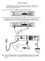
Quick Setup
Your GROOVE 1200 is ready to play right out of the box. After reviewing
this Quick Setup page, feel free to experiment with the controls and
create your own unique sound.
1
Set tone controls flat and Master Volume Control down.
2
Connect input, AC power cord, footswitch cable, and speaker cable. If using an
active bass, toggle the Active/Passive Switch to Active. If the Red Clip
Indicator lights while playing, toggle the Active/Passive Switch to Passive.
15
PRE EQ
LIFT
POST EQ
TUNER OUT
A
A
GROUND
MODEL: GROOVE 1200
15
BREAKER
RISK OF ELECTRIC SHOCK
DO NOT OPEN
DIRECT OUTPUT
ATTENTION
RISQUE DE CHOC ELECTRIQUE-NE PAS OUVRIR
EFFECTS LOOP
2001124
SERIAL NUMBER
CAUTION
CHASSIS SURFACE HOT
ATTENTION
DESIGNED IN USA
MADE IN CHINA
SUPERFICE DE CHASSIS CHAUDE
SPEAKER OUTPUT
SEND
RETURN
FOOTSWITCH
Insert and twist
clockwise to lock.
SOLO
Speaker
Cabinet
3
Turn on the Power Switch, adjust the Gain Control until the Green Signal
Indicator lights regularly, turn up Master Volume Control slowly, and start
playing.
5
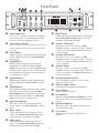
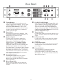
Front Panel
a
Guitar Input Jack:
b
Active/Passive Switch
c
d
e
f
g
h
i
j
This is a 1/4" 2-conductor input jack for plugging
in your instrument. It is intended for bass guitar
but will accept other instruments as well.
k
Set this switch to Active when using an active bass
guitar. Setting to Active will lower the input gain
by 12 dB.
Gain Control:
Adjust clockwise to increase the amount of preamp
volume. When set too low, the Signal Indicator
will not light.
Signal Indicator:
Indicates when sufficient signal is applied to the
preamp. Adjusting the Gain Control will affect
this.
Mute Indicator:
This indicator will light when the preamp is muted.
This can be done by either pressing the Mute
On/Off Button on the front panel or by pressing
Mute on the footswitch. Note: The Tuner Out
Jack will still be active when this is lit.
Mute On/Off Button:
When this switch is active the preamp will be
muted. However, the Tuner Out Jack is always
active.
Bass Control:
Controls the amount of low frequency in the
signal. The Normal / Sub Switch changes the
center frequency for this control. (See k)
Mid Control:
Controls the amount of mid frequency in the
signal. The Normal / Shift Switch changes the
center Frequency for this control. (See l)
6
Normal / Sub Switch:
When this switch is set to Normal, the Bass
Control frequency is centered at 100Hz. When this
switch is set to Sub, the Bass Control frequency is
centered at 50Hz.
l
Normal / Shift Switch:
m
Normal / Define:
n
Graphic Equalizer Section:
Clip Indicator:
Indicates when the input signal has reached
maximum level. Note: The Active / Passive
Switch is the only control on the amplifier that has
an effect on this. If the switch is set to Active and
the Clip Indicator still lights, lower the output of
your instrument to correct.
High Control:
Controls the amount of high frequency in the signal.
The Normal / Define Switch changes the center
frequency of this control. (See m)
When this switch is set to Normal, the Mid
Control frequency is centered at 800Hz. When this
switch is set to Shift, the Bass Control frequency is
centered at 400Hz.
When this switch is set to Normal, the High
Control frequency is centered at 3KHz. When this
switch is set to Define, the High Control frequency
is centered at 5KHz.
This 9-band graphic equalizer is used to finely
adjust the sound to taste.
o
p
q
Solo Indicator:
r
Solo On/Off Button:
s
Power Jewel:
Master Volume Control:
Controls the overall output of the amplifier.
Power Switch:
Turns AC power on and off.
Indicates when the Solo On/Off Button is pressed.
This will also light when Solo on the footswitch is
pressed.
When this is active, the signal to the power amp
will be boosted by 6dB.
Indicates when AC power is applied to the
amplifier.
Rear Panel
15
25
PRE EQ
LIFT
POST EQ
TUNER OUT
A
A
GROUND
MODEL: GROOVE 1200
15
BREAKER
RISK OF ELECTRIC SHOCK
DO NOT OPEN
DIRECT OUTPUT
ATTENTION
RISQUE DE CHOC ELECTRIQUE-NE PAS OUVRIR
EFFECTS LOOP
2001124
SERIAL NUMBER
CAUTION
CHASSIS SURFACE HOT
DESIGNED IN USA
MADE IN CHINA
t
Circuit Breaker:
u
Power Cord:
v
ATTENTION
SUPERFICE DE CHASSIS CHAUDE
SEND
SPEAKER OUTPUT
y
This circuit breaker will trip when too much
current is applied to the amplifier. To reset: Turn
off Power Switch, press circuit breaker button,
and turn the Power Switch on. Note: If the
Circuit Breaker trips repeatedly when AC power
is applied, take the amplifier to an authorized
service center for repair.
z
This supplies AC power to the amplifier. If the
cord becomes damaged, take the amplifier to an
authorized service center for repair.
{
Speaker Outputs:
Use these jacks to connect the amplifier to
speaker cabinets using heavy duty Speakond
speaker cables. These jacks are connected
together internally. See Amplifier Loading
Chart (Page 8) for speaker cabinet loading
information. Note: To prevent overheating and
possible loss of signal, do not connect a load
lower than 2 ohms. (To connect a cable: Align tab
on speaker cable connector slot. Insert and twist
one quarter turn clockwise to lock. To remove a
cable: Pull back release button on cable connector,
twist connecter counter clockwise one quarter
turn, and pull out connecter.)
w
Ground Lift Switch:
x
Direct Output Jack:
|
}
Activating this switch removes the ground
connection on the Direct Output Jack.
Removing the ground connection will eliminate
related signal hum.
This is a line level output used to connect the
amplifier to another device, such as a mixer or
recorder.
7
RETURN
FOOTSWITCH
Pre EQ / Post EQ Switch:
When set to Pre EQ, the Direct Output Jack signal
will be unaltered by the EQ sections of the preamp.
When set to Post EQ, the Direct Output Jack
signal will reflect the entire sound (including EQ
settings) of the preamp. Note: The Master Volume
Control and Solo On/Off Button have no effect on
the Direct Output Jack signal.
Tuner Out Jack:
Use this jack to connect to a tuner or other line level
device. This jack is always active and is a pre-gain
output.
Effects Send Jack:
Use this jack to connect to the input of an external
effects processor. This jack can also be used as a
preamp out.
Effects Return Jack:
Use this jack to connect to the output of an external
effects processor. This jack can also be used as a
power amp in.
Footswitch Jack:
This 3-conductor 1/4” jack may be used for
connecting a footswitch to the amplifier
(Footswitch model KAC-GFS100 is included with
the amplifier). The footswitch will then control the
Mute and Solo features.
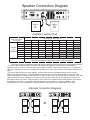
Speaker Connection Diagram
15
PRE EQ
LIFT
POST EQ
TUNER OUT
A
A
GROUND
15
MODEL: GROOVE 1200
BREAKER
RISK OF ELECTRIC SHOCK
DO NOT OPEN
DIRECT OUTPUT
ATTENTION
RISQUE DE CHOC ELECTRIQUE-NE PAS OUVRIR
EFFECTS LOOP
2001124
SERIAL NUMBER
CAUTION
CHASSIS SURFACE HOT
DESIGNED IN USA
MADE IN CHINA
ATTENTION
SUPERFICE DE CHASSIS CHAUDE
SEND
SPEAKER OUTPUT
Cabinet
Cabinet
A
B
RETURN
FOOTSWITCH
Amplifier Loading Chart
Speaker cabinet
loads (ohms) applied
to the amplifier
Cabinet
B’s
Impedance
Cabinet A’s Impedance (ohms)
open
16
8
5.33
4
3.20
2.67
2
open
16
8
5.33
4
3.2
2.67
2
16
8.00
5.33
4.00
3.20
2.67
2.29
1.78
8
5.33
4.00
3.20
2.67
2.29
2.00
1.60
5.33
4.00
3.20
2.67
2.29
2.00
1.78
1.45
4
3.20
2.67
2.29
2.00
1.78
1.60
1.33
3.2
2.67
2.29
2.00
1.78
1.60
1.46
1.23
2.67
2.29
2.00
1.78
1.60
1.46
1.34
1.14
2
1.78
1.60
1.45
1.33
1.23
1.14
1.00
Total load on amplifier Note: To prevent overheating and possible loss of signal, do
open
16
8
5.33
4
3.20
2.67
2
not use any combination of cabinets that results in a box that is shaded.
This chart can help you determine what load (ohms) is present on the amplifier when using multiple cabinets.
- To use this chart with two cabinets (A and B), find cabinet A’s impedance (ohms) column and cabinet B’s
impedance row on the chart. The total load on the amplifier is shown in the box where they meet. For example: If
cabinet A’s impedance is 8 ohms and cabinet B’s impedance is 4 ohms, the total load on the amplifier would be 2.67
ohms.
- To use this chart with three or more cabinets, find the total load for two cabinets and then use the result for
cabinet A’s impedance column. The third cabinet will then be used for cabinet B’s impedance row on the chart.
Find the total load on the amplifier and repeat if more cabinets are used. For example (using 3 cabinets): If the first
cabinet (cabinet A) has an impedance of 16 ohms and the second (cabinet B) has an impedance of 8 ohms, the
total load would be 5.33 ohms. Using this load (5.33) as cabinet A’s impedance and a third cabinet’s (new cabinet
B) impedance of 4 ohms, you would find that the total load on the amplifier is 2.29 ohms. Note: It is not
recommended to use any combination of cabinets that has a resulting load in a shaded area of the chart.
Alternate Connection Diagrams
PRE EQ
GROUND
15
TUNER OUT
PRE EQ
GROUND
15
TUNER OUT
A
A
A
A
15
MODEL: GROOVE 1200
POST EQ
LIFT
15
BREAKER
RISK OF ELECTRIC SHOCK
DO NOT OPEN
MODEL: GROOVE 1200
RISK OF ELECTRIC SHOCK
DO NOT OPEN
SERIAL NUMBER
CAUTION
CAUTION
CHASSIS SURFACE HOT
ATTENTION
SUPERFICE DE CHASSIS CHAUDE
EFFECTS LOOP
2001124
CHASSIS SURFACE HOT
DESIGNED IN USA
MADE IN CHINA
DIRECT OUTPUT
ATTENTION
RISQUE DE CHOC ELECTRIQUE-NE PAS OUVRIR
EFFECTS LOOP
2001124
SERIAL NUMBER
POST EQ
LIFT
BREAKER
DIRECT OUTPUT
ATTENTION
RISQUE DE CHOC ELECTRIQUE-NE PAS OUVRIR
SPEAKER OUTPUT
SEND
RETURN
8 Ohms
8 Ohms
8 Ohms
8 Ohms
DESIGNED IN USA
MADE IN CHINA
FOOTSWITCH
=
Total Load On Amplifier = 2 Ohms
ATTENTION
SUPERFICE DE CHASSIS CHAUDE
SPEAKER OUTPUT
SEND
RETURN
8 Ohms
8 Ohms
8 Ohms
8 Ohms
Total Load On Amplifier = 2 Ohms
8
FOOTSWITCH
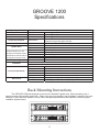
GROOVE 1200
Specifications
Input Impedance
Output Power
200K Ohm
450 Watts
750 Watts
1200 Watts
Frequency Response
20HZ-20kHz
Hum & Noise
System Gain
All measurements taken with 1 KHz
input signal, Tone controls flat, Gain and
Volume Maximum. Measured at effects
send output jacks on rear unless noted.
Amplifier Type
Footswitch
Power Requirements
Dimensions
-60db
27db
15db
25db
27db
32db
8 Ohms @ 5% THD
4 Ohms @ 5% THD
2 Ohms @ 5% THD
Actual response is tailored to speakers for accurate acoustical
response using a bass guitar as input.
Residual Noise, all level controls 0% (minimum)
Preamp output
Preamp output, Active
Tuner output
Direct output
Power amp gain
Class B
Descrete device Class B amplifier
Any non-momentary two-button foot switch can be used.
Use any standard tip-ring-sleeve cable
USA/Canada
120VAC/60Hz, 1500W nominal
Europe
230VAC/50Hz, 1500W nominal
UK
230VAC/50Hz, 1500W nominal
Australia
240VAC/50Hz, 1500W nominal
Japan
100VAC/50-60Hz, 1500W nominal
mm/kg
89 (Height) x 483 (Width) x 390 (Depth), 14 kg
Inches/Pounds
3.5 (Height) x 19 (Width) x 15.5 (Depth), 31 lbs
Rack Mounting Instructions
The GROOVE 1200 was designed to mount into a standard 2-space rack. When mounting, use 4
screws to secure the amplifier to the rack. When using only one amplifier, use the bottom 2 spaces in the rack.
However, if more than one amplifier is used, leave one space open between the amplifiers to ensure proper
ventilation (shown below).
9
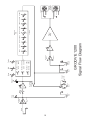
10
Input
Active = 12 db
Cut
Active/Passive
Switch
Tuner
Out
Clip
LED
Mute
Switch
Direct
Out
Pre/Post
EQ Switch
Gain
Signal
LED
50 Hz
Preamp
Out
Power
Amp In
3 KHz
5 KHz
Define
400 Hz
Normal
Shift
Normal 800 Hz
Sub
6 db Boost
Solo Boost
Switch
Treble
Normal 100 Hz
Mid
50 Hz
Volume
30 Hz
100 Hz
GROOVE 1200
Signal Flow Diagram
Ground
Lift
Switch
Bass
+/- 12 db
400 Hz
Power
Amp
200 Hz
Graphic
EQ
+1
-1
+1
-1
800 Hz 1.6 KHz 3.2 KHz 6.4 KHz
Speaker
Outputs
EC Declaration of Conformity
We:
Kustom Musical Amplification Inc.
4940 Delhi Pike
Cincinnati, OH 45238
Tel: 1-513-451-5000 Fax: 1-513-347-2192
Declare that the product
Product name:
Kustom
Product model number:
Groove 1200
to which this declaration relates is in conformity with the following standards;
EN55013 (A12) : 1995
Limits and methods of measurement of radio disturbance characteristics of broadcast receivers and
associated equipment.
EN55020: 1995
Electromagnetic immunity of broadcast receivers and associated equipment.
EN61000-3-2: 1995
Limits for harmonic current emissions (equipment input current < 16A per phase).
EN61000-3-3: 1995
Limitation of voltage fluctuations and flicker in low voltage supply systems for equipment with
rated currents < 16A.
EN55103-1: 1995
Electromagnetic Compatibility - Product family standard for Audio, Video Audio-visual and
entertainment Lighting Control Apparatus.
EN60065: 1994
Safety requirements for main operated electronic and related apparatus for household and similar
general use.
Following the provisions of EU Council Directive(s): 72/73 EEC and 89/336/EEC.
We the undersigned, hereby declare that the equipment specified above conforms to the aforementioned directive(s).
Name of authorized person: Rick Kukulies, VP Engineering
Signature:______________________
Date: 05 June 2001
Kustom Musical Amplification Inc. (BC Rich)
4940 Delhi Pike
Cincinnati, OH 45238
Tel: 1-513-451-5000 Fax: 1-513-347-2192
11
Kustom Amplification Inc., 4940 Delhi Pike, Cincinnati, OH • USA
(800) 999-5558 Web: www.kustom.com