1
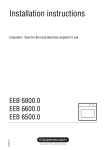
Gas Cooktop
Installation, User and Service Instructions
GMS 955.1
IMPORTANT: SAVE FOR LOCAL ELECTRICAL INSPECTOR’S USE.
READ AND SAVE THESE INSTRUCTIONS FOR FUTURE REFERENCE.
OBSERVE ALL FEDERAL, STATE AND LOCAL CODES AND ORDINANCES
WARNING: If the information in this manual is not followed exactly, a fire or explosion may result causing
Property damage, personal injury or death.
Do not store or use gasoline or other flammable vapors and liquid in the vicinity of this or any other appliance
WHAT TO DO IF YOU SMELL GAS
1.
2.
3.
4.
5.
Do not try to light any appliance
Do not touch any electrical switch
Do not use any phone in your building
Immediately call your gas supplier from a neighbor’s phone. Follow the gas supplier’s instructions
If you cannot reach your gas supplier, call the fire department.
Installation and service must be performed by a qualified installer, service agent or gas supplier.
Read this instruction booklet before installing and using the appliance
The Manufacturer will not be responsible for any damage to property or to persons caused by incorrect installation
or improper use of this appliance
The manufacturer reserves the right to make changes to its products when considered necessary and useful, without
Affecting the essential and operating characteristics.
This appliance has been designed for non-professional, domestic use only!
INDEX… … … … … … … … … … … … … … … … … … … … … … … … … … … … … … …
Page 1
Gas installation requirements … … … … … … … … … … … … … … … … … … … … …
Page 2
Electrical installation requirements… … … … … … … … … … … … … … … … … … …
Page 2
Dimension and Distance Requirements… … … … … … … … … … … … … … … … … .
Page 3
Overall and Cutout Dimensions… … … … … … … … … … … … … … … … … … … … .
Page 4
Gas tubing and Electrical location … … … … … … … … … … … … … … … … … … … …
Page 4
Installing the Cooktop… … … … … … … … … … … … … … … … … … … … … … … …
Page 4-5
Gas connection … … … … … … … … … … … … … … … … … … … … … … … … … … … …
Page 5
Electrical connection… … … … … … … … … … … … … … … … … … … … … … … … … ..
Page 6
Room Ventilation… … … … … … … … … … … … … … … … … … … … … … … … … … …
Page 6
Cooktop L.P Gas Conversion… … … … … … … … … … … … … … … … … … … … … … .
Page 6-7
User Instructions… … … … … … … … … … … … … … … … … … … … … … … … … … …
Page 8
Maintenance – Warranty and Service Information… … … … … … … … … … … … … .. Page 9
Wiring Diagram- parts identification… … … … … … … … … … … … … … … … … … … … Page 9
1
Gas Installation Requirements
This appliance shall be installed by an authorized person and installed in accordance to
The manufactures installation instructions. IMPORTANT: This Appliance must be installed in strict
Compliance with all Federal, State and Local laws (Where applicable) In the absence of local codes, the installation must
conform to American National Standards, National Fuel Gas Code ANSI Z223.1 – Latest edition ** or B149.1
If local code permits, a flexible metal appliance connection with the new AGA or CGA certified
Design, max. 5 feet (1.5 mm) long, ½ “I.D. recommended for connecting this Cooktop to the gas supply
line. Do not bend or damage the flexible connector when moving the Cooktop. The pressure regulator has ½ “
female pipe thread. You will need to determine the fitting required, depending on the size of your gas supply line,
the flexible metal connector and the shutoff valve.
The appliance and its individual shutoff valve must be disconnected from the gas supply piping system for testing. The
maximum pressure applied to the unit for testing must not exceed ½ p.s.i (3.5kPa). The minimum pressure required to test
the system must be at least 1” Water column (249 Pa) above the inlet specified manifold pressure to the appliance. The
maximum inlet gas supply pressure to the regulator must not exceed 20” Water column (5 kPa).
The supplied regulator must be installed between the main gas supply line and the Cooktop. The regulator must be set to
the proper gas supply. The gas pressure required on this unit is 4” Water column (Natural) and 11” Water column (Liquid
Propane). The regulator is set to NAT from the factory.
This unit is shipped from the factory set for NATURAL GAS. This unit is supplied with a conversion kit to convert this
unit to Liquid Propane (L.P.). You will find this kit along with the installation instructions and the operation booklet.
If the unit is converted it is recommended that you save all the Natural gas orifices in the event that the unit is to be
converted back to natural gas In the future.
WARNING! Only a licensed and certified Gas installer should attempt the conversion.
Electrical Installation Requirements
This appliance, when installed by a licensed and certified electrician must be electrically grounded in accordance
With all Federal, State and Local laws (Where applicable). In the absence of local codes, the installation must conform
To the National electrical Code, ANSI/NFPA 70.
This unit requires a three-prong 120 volt, 15 amp 60 Hz wall connection. The unit is supplied with a 5 foot three
Prong plug. The outlet must be grounded and polarized. A non-polarized outlet may cause erratic operation of the
Ignition system.
WARNING! Electrical grounding instructions: This appliance is equipped wit h a three prong grounded plug for your
protection against shock hazard and should be plugged directly into a properly grounded receptacle. Do not cut or remove
the grounding prong from this plug.
2
Dimensions and Distances requirements
Cabinet overhead and side clearances
The minimum overhead clearances shall be in accordance with the minimum values indicated in Fig. 1 for square angle
cuts and Fig. 2 for rounded cuts.
Fig. 1
Fig. 2
*
*
*
Minimum Clearances
Inches
L2
L3
L4
L5
L6
L7
L8
L9
L11
1 9/16”
3 3/8”
18”
24”
13”
33 7/8”
¾”
3 15/16”
32”
*
* Refer to Fig 3 for Cooktop clearance dimensions
Millimeters
40
86
457
610
330
860
20
100
813
All Range hoods and exhaust shall be installed in accordance with manufacturers
instructions. However, in no case shall the clearance between the top of the highest
burner of the cooking appliance and the range hood be less then 30” (762 mm).
Any other downward facing combustible surface less than 23 5/8” (600 mm) above the
top of the highest burner shall be protected for the full width and depth of the cooking
area.
Under no circumstances shall the clearance to any surface be less than 17 ¾” (450 mm)
and the maximum depth for the overhead cabinets is not to exceed 13” (330 mm).
Cooktop clearance dimensions
Fig 3 shows the minimum clearances between the Cooktop surface and adjacent cabinetry. B1 is the minimum distance
between the front edge of the Cooktop and the front edge of the cabinet. B2 and B4 are the minimum clearance between
left / right side edge of the appliance and the side wall and B3 is the minimum clearance between the back edge of the
cooktop and the back cabinet wall.
Minimum Clearances
Inches
B1
B2
B3
B4
1 3/8”
3½“
3”
3 ½”
Fig. 3
Millimeters
35
90
76
90
3
Overall and Cutout Dimensions
Below are the required cutout dimensions and the overall dimensions of the cooktop as indicated in Fig. 4
Overall
Fig. 4
Cutout
Inches
Millimeters
Inches
Millimeters
W
33 7/8”
860
W
33 1/16”
840
D
19 11/16”
500
D
18 7/8”
480
Gas tubing and electrical location
Fig 5 shows the location of the gas supply and electrical outlet location. Fig 6 shows the placement of the supplied gas
regulator. Refer to the chart for the required measurements.
Fig. 5
Inches
A
B
C
D
1 9/16”
8 ¼”
8 ½”
1/8”
Fig. 6
millimeters
45
210
215
22
Installing the Cooktop
Please inspect all packing materials before discarding. After removing all packaged installation Parts from the box, make
sure that the Cooktop is not damaged and is suitable for the particular Gas being used (Natural gas or liquid Propane). The
unit is shipped ready to install to Natural gas. If the supplied gas is Liquid Propane (L.P.) Please refer to Page for gas
conversion.
To prevent liquids from leaking accidentally into the underlying storage space, the appliance is equipped with a special
gasket. Lay out the gasket and remove the protective coating and apply the gasket along the edge of the cabinet opening as
indicated in Fig. 5.
Fig. 5
4
Install the Cooktop into the cabinet. Install the supplied hold down brackets (A) to the underside of the Cooktop using the
supplied Phillips head screws (B) as shown in Fig. 6. Slide the hooks into position and secure the cooktop to the
countertop. Trim any exposed gasket seal.
Fig. 6
Gas Connection
Check the ‘gas type’ sticker attached to the Cooktop. Details of the injector sizes used are recorded on the data plate
located on the base of the Cooktop.
Remove the regulator from the cartoon and install to the Cooktop. The inlet connection has a ½” B.S.P. male thread. It
Is essential that the elbow on the appliance be held firmly with a spanner wrench when connecting the supply.
DO NOT OVER TIGHTEN. The regulator is adjustable for both NAT gas (4” w.c.) and L.P gas (11” w.c.)
After installing the gas supply and securing all connection make sure that all controls knobs are set to the “OFF” position.
and turn on the gas supply to the unit. Using soap and water solution or an electronic gas leak detector, check each gas
connection one at a time. If using a liquid solution, completely cover the entire connection and inspect for
bubbles. If any leaks are discovered, shut off main supply, repair the leak and retest. Make sure that the work area is
properly ventilated. When all connections have been tested and no leaks discovered.
WARNING! Do not use an open flame, such as a match or cigarette lighter to check for leaks. Serious injury or death
could result if a leaking connection is ignited.
To check inlet gas pressure being supplied to the Cooktop proceed with the following:
A)
B)
C)
D)
Disconnect electric power before pressure checking is carried out
Take off one of the gas burner caps and the relative flame spreader in order to gain access to the burner orifice.
Attached the test meter to the outlet of the orifice. Turn the gas valve knob to the maximum position and keep the
knob depressed. The meter should register 4” w.c. on NAT gas and 11” w.c. on LP gas.
Once the testing is complete, replace the burner cap and the flame spreader and reconnect electrical supply
To test the operation of the Cooktop, turn on each burner and check for proper operation. Check each burner for a clear
blue flame without yellow tipping. If the flame appears to be uneven or excess yellowing, check the positioning of the
burner cap and flame spreader.
Sometimes the burners will not ignite immediately and seem to “Blow” slightly when they ignite. This is normal on LAP
gas due to the heaviness of the gas. Also, if any air is present in the gas system, a “Sputtering” condition can occur. Both of
these conditions are normal and do not affect the performance of the Cooktop.
If after following the instructions given and satisfactory performance cannot be obtained, contact your local gas authority
for advice and assistance
5
Electrical Connection
WARNING! This appliance is equipped with a three-prong grounding plug for your protection against shock hazard and
should be plugged directly into a properly grounded receptacle. Do not cut or remove the grounding prong from the plug.
Please refer to Fig. 5 0n page 5 for the location of the electrical wall plug.
This unit requires a 15 amp polarized and grounded wall outlet. Failure to proper polarize the outlet may cause erratic
discharges from the burner spark system. This unit is supplied with a three-prong 120-volt 60 Hz cord. The cord is ___ in
length.
Room Ventilation
An exhaust fan may be used with the appliance; in each case it shall be installed in conformity with all Federal, state and
local building codes. Please note that the use of an exhaust hood may affect other vented appliances
Conversion of unit to operate on L.P. Gas
WARNING! This conversion must be performed by a certified and licensed gas installer. Failure to comply may result in
improper operation, which could result in injury or death. Please consult your local governing officials for all Federal, State
and local building codes. Failure to comply may result in the voiding of the product warranty.
Note:
This unit is shipped from the factory to operate on NATURAL gas. The following procedures are to covert from NAT to
Liquid propane (L.P.) operation.
Replacement procedure- burner orifices
1)
2)
3)
Remove all burner grates and place in a secured location.
Remove all five burner caps and flame spreader and place in a secured location.
Using a 7 mm socket or spanner wrench, locate the burner orifice at the base of the burner box and remove using a
counter clockwise rotation. Fig. 7 shows the location of the orifice.
Note:
Fig. 7
Please place all five NAT gas
orifices in a secured location
in the event that the unit is to
be converted back to NAT gas
in the future
4)
Reinstall all five burner caps and flame
spreaders. Make sure the caps are
positioned properly on the burner base.
Proceed to the By-pass screw adjustment on page 7
6
By-pass jet adjustment for low flame setting
1)
2)
Turn the right front burner on to ignite. Once lit, turn to the lowest setting (small flame).
Remove the knob from the cooktop and place in a secured location.
Locate the adjustment screw shown in Fig. 8 in the center of the burner valve shaft.
Fig. 8
Increase
Larger Flame
3)
Decrease
Smaller Flame
Using a small flat blade screwdriver, locate and adjust the screw to obtain a proper flame height. A clockwise
adjustment will decrease the output while a counterclockwise adjustment will increase the output. Adjusting the
screw too low will result in the flame going out while adjusting too high will result at a larger flame than required
for a simmer.
Note: A properly adjusted low flame setting will result in the flame reaching to the underside edge of the burner cap!
Regulator adjustment for L.P.Gas
The gas pressure regulator supplied is a universal type that can be set for either Nat or L.P gas. The unit is shipped set
To NAT gas.
1)
Unscrew the cap shown in Fig. 9 to expose the white adjuster which is screwed into the underside of the metal cap.
Fig. 9
2)
3)
If you notice, the white striker has the letters NAT at the base. Unscrew the white striker from the base and rotate
180 degrees and re-install the striker in the cap. You will now see the Letters LP which now indicates that the
Regulator is now set to Liquid Propane (L.P.).
Re-install the metal cap into the regulator housing and hand tighten. The regulator is now set to L.P.
Note: If the unit is converted back to NAT gas in the future, follow the above steps to convert back to NAT gas operation.
The unit is now ready to be operated on L.P gas. … … … … … … … … … … … … … … ..Conversion Complete!
7
User instructions
WARNING!
Keep the appliance area clear and free from combustible materials, gasoline and other flammable vapors and liquids.
Do not store dangerous or flammable material in the cabinet areas above the appliance. Store all flammable materials
In a safe lace to avoid potential hazards.
For safe use of appliances, do not use this unit as a source of space heating. Do not use aerosol sprays in the vicinity of the
appliance while it is in operation.
Operation procedures
A diagram is etched on the control panel above each knob which indicates which burner corresponds to that knob.
Manual ignition:
Manual ignition is always possible even when the electrical supply is cut off or in the vent of a prolonged power failure.
Turn the knob that corresponds to the burner selected counterclockwise to the MAXIMUM position at the etched star
(Large flame) and place a lit match up to the burner. This unit operates on a thermocouple safety system. Keep the knob
depressed for 5- 8 seconds in order for the unit to operate. If the flame is extinguished the thermocouple will cool and the
safety system will kick in and shut off the gas supply to the burner orifice. In order to relight the burner repeat the
procedures outlined in this paragraph.
Automatic electric ignition:
Turn the knob that corresponds to the burner selected counterclockwise to the MAXIMUM position at the etched star
(Large flame) and press down on the knob to activate the automatic ignition system. When the burner ignites keep the knob
depressed for an additional 5-8 seconds to allow the flame to heat the thermocouple. If the burner does not remain lit after
releasing the knob repeat the procedure outlined in this paragraph.
Tips for using the burners correctly
Fig. 10
- Use suitable pots for each burner as shown in Fig. 10. and as shown in the Chart below
- Always use pots with a cover.
- When the liquid is boiling, turn down the knob to the MINIMUM position.
- Dry the bottom of the pan before placing it on the Cooktop
- Use pots with a flat, thick bottom with the exception of wok cooking
- When using the burners, ensure that the handles of the pans are correctly
positioned. Keep children away from the appliance.
- When cooking foods with oil and fat, which are flammable, the user should
not leave the appliance unattended.
Recommended pan diameters
Burner
Small
Medium
Large
Wok
Inches
3 ½ “– 5 ½ “
5 ½” - 10 ¼”
7” – 10 ¼”
8 ¾” -10 ¼”
Millimeters
90 -140
140-260
180 -260
220- 260
Note: The use of a gas cooking appliances produces heat and humidity in the room where it is installed. Therefore, proper
ventilation in the room is needed and natural ventilation openings must remain unobstructed.
8
Maintenance
-
Never use an abrasive cleaner
Before cleaning the appliance it is available that the unit should be disconnected from the power supply.
Cleaning the work surface periodically. Clean the burner heads, the enameled steel pan supports and the burner caps
using warn water and a mild detergent. Avoid using steel wool for the fibers of the pad could affect the electronic
igniters.
Any spillage must always be removed as soon as possible using a rag or damp cloth. If the gas valves become difficult
the operate due to corrosion or normal wear and tear, please contact Küppersbusch service at the number shown on
page 10.
Enameled parts should be cleaned frequently with soapy water. Never use abrasive powder or cleansers. Do not leave
acidic or alkaline substances on the enameled parts (Such as vinegar, lemon juice, salt, tomato sauce, etc.) and do not
wash the enameled parts while they are still hot.
Clean the stainless parts with soapy water and then dry with a soft cloth. The shine is maintained by periodically using
a suitable product which can be found in a supermarket which is specifically designed for stainless steel. Never use
abrasive powders.
The burner caps may be removed from the Cooktop and washed in soapy water and then dried thoroughly. Before
replacement on the burner head ensure that the holes are free of debris. Erratic flame dispersement from the burner
head is a sign of clogged ports on the burner head.
-
-
-
-
Parts identification – Wiring Diagram
1
2
3
4
7
8
10
11
13
R.F Small Burner
L.R and RR Medium Burner
L.F Large Burner
Center Wok Burner
L.F Burner Knob
R.F Burner Knob
L.R Burner Knob
R.R Burner Knob
Center Burner Knob
Warranty
-
2-year Parts and labor warranty
5-Year Functional Parts Warranty
WIRING DIAGRAM
After Sales Service
If in the event of a problem that you can’t easily fix yourself,
Please contact the Küppersbusch Service department at:
1-800-251-7790
For parts ordering, use & care and all other general
Questions, please contact the Küppersbusch Customer
Service department at:
1-800-459-0844
Küppersbusch USA
4920 W. Cypress Street, Suite 106
Tampa, Florida 33607
Telephone: 800-459-0844 Fax: 813-288-8604
After Sales Service: 800-251-7790
www.kuppersbuschusa.com
Küppersbusch USA is a division of Teka USA
9