1
MANUFACTURER'S UMITED ONE YEAR
WARRANTY
LEGACY®
LEGACY SOUND CORP. warrants this unit to be free from defective material or workmanship and will repair or
replace this unit or any part thereof if it proves defective in normal use or service within one (1) years from
the date of original purchase.
Our obligation under this warranty is limited to repairin� or replacing, at our discretion, the defective instrument
or any part thereof when it is returned, transportation prepaid to the Legacy Service Center at the address
below. This warranty will be considered void if the unit has been tampered with, improperly serviced, subjected
to abuse or misuse or if installed in a commercial vehicle. This warranty does not cover accidental damage.
When returning this unit for service, please include $15.00 for return postage and handling. Send your unit to:
IMPORTANT: Pack carefully in original carton if possible. We are not
responsible for damage incurred in returning items for repair. A letter
stating your exact street address, daytime phone number, and the
problem you are experiencing should be included. You must also enclose
a copy of the original receipt as proof of date of purchase.
F OR YOUR PROTECTION
Completely and immediately mail the Product Registration Card
so that we may contact you directly in the event a safety
notification is issued in accordance with the 1972 Consumer
Product Safety Act, or for other reasons Legacy may deem
necessary.
TECHNICAL S U PPORT HOTLINE
Our technical department will gladly answer any questions
you may have about our products. They cannot, however
tell you the status of a repair, or handle other customer
service situations.
1-800-934-2277
Monday through Thursday, 9AM to 5PM
Friday 9AM to 2PM Eastern.
LEGACY®
VVVVVV�legac::ycaraLldlo_c::ol'T"ll
LEGACY SERVICE CENTER
1600 63rd Street
Brooklyn, NY 11204
-4!S..s.
-.:...s.
-7'..s.
r--.....
.
-s. ..s.
.
_- .. �..s.
__...
�
.
... - ......s.
....
.
...
..
-�;S..s.
« .-�....s.
« .-"4.��
« .-��� .. .,
�...
congratulations...
Congratulations on !.lour purchase or an American series ampllrler. You have purchased
a quallt!.l product designed and engineered to give !.IOU man!.l !.Iears or uncompromlsed
musical service. American series ampllrlers are designed with the latest technolog!.l available.
which provtdes headroom ror even the most demanding peaks and d!.lnamlc ranges
round on modem CD's and recordings.
table of contents
reatures and speclrlcatlons
LA-I.qOO/LA-200ID
LA-SS9/LA-7S9/LA-9S9
LA-ISS9/LA-23S9/LA-2SS9
LA-6S9/LA-IOS9
electrical connections
LA-I.qOO/LA-200ID
LA-SS9/LA-7S9/LA-9S9
LA-ISS9/LA-23S9/LA-2SS9
LA-6S9/LA-IOS9
stereo/mono Input connections
LA-SS9/LA-7S9/LA-9S9
LA-ISS9/LA-23S9/LA-2SS9
2/.q channel Input connections
LA-6S9/LA-IOS9
2-9
10-11
high level Input connections
17
s!.lstem wiring speaker connections
18
mono Input connections
19
speaker connections
20-21
speaker wiring
22
mounting and Installation
23
24
25
LA-6S9/LA-IOS9
LA-SS9/LA-7S9/LA-9S9
LA-ISS9/LA-23S9/LA-2SS9
LA-6S9/LA-IOS9
LA-6S9/LA-IOS9
12-15
LA-I.qOO/LA-200ID
16
protection clrcultr!.l and troubleshooting
precautions
LEGACY AIII.rlcan OWNI!I"
MANUAl:
LEGACY Alllarlnn OW.U'I MANUAL
-
1
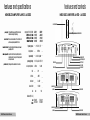
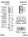
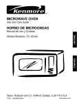
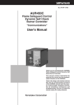
features and specifications
MONO BLOCK AMPLIFIER LA-1400 LA-20010
features and controls
MONO BLOCK AMPLIFIER LA-1400 LA-20010
•
•
sub sonic level control
pOWIr ••ppli.
Stiffly regulated PWM power supplies. MOSFET switches maintain
raled power over a wide range of battery voltages.
..II IOnic DDnb'a1
When the sub sonic selector switch is in 'ON" mode, this fitter control
fJ8fIIIi/s continuously variable adjus_t from 10 IrJ 100Hz.
... baa.. 1l1li DDnb'a1
This control pennil3 adjustment of the bass leve/ up to an increase of
approximalely up IrJ 18dB.
erDllOVll' I.. .... lilllr
Adjustable from 20Hz to 250Hz with a slope of 24dB per octave.This
allows for the adjustment of the upper point of the frequency bandwidth
and the respective subwoofer.
prellctiDi lir.H..,
Protection against thermal, overload and short circuit conditions.
output pawer @ 14Av DC, 5111z
RMS I'll",., lit @4 Ohms
RMS I'll",., lit @2 Ohms
MulIII/IIII I'll",., 0/ItpIIt
lrequenc,respanse
LA·14OB
LA·IOBID
115WMONO
215WMONO
2OOOWMONO
2S0WMONO
38SWMONO
3000WMONO
--
2DHz-250Hz(±3d8J
pawenupply voltage
min speaker Impedance
--
2oomV-6VAdjustable
1-4 Ohms
2-4 Ohms
0.1%
SIll ration
>9Od8
bass boast
0-+18d8
sub sonic liltar
10-1ooHz
40A
I11III
213x43x305
10.14x1.69x12
®®
.@I. ®®
.@I.
. .....
���\i
SII
......
0
"0-
���
@
I
power/protection LED
low pass frequency control
phase shift switch
sub sonic switch
input level control
@
\���
Iil!ill I�@FISE@�I
I
power fuse
@
213x43x330
10.14x1.69x13
power fuse
[���
I����I
't'O'l
I
power terminals
50A
�
lJass boost level control
line level outputs
power terminals
LEGACY Am.rlcan OWNEII'S M.MUAL
... UUT
LI
---";�""',I;",.--_
.�-
line level inputs
dimensions (W x H x L)
Inchtls
���
,.....-
--
14.4V OC Neg. Ground (10.5-16V)
IJl.D
luse
@
10K Ohms
input impedance
input sensitivity
--
----+-+---
-
,
I
l!i!ill HH 1�1!r!I��1
I
't'O'l-
I
@
speaker connections
-
-
��m
,
��m
@
speaker connections
�
LEGACY Am.rlun O.tn.'s MANUAL
•
3
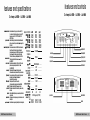
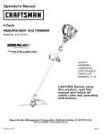
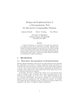
features and controls
2 ch amp LA-SSg LA-7S9 LA-9S9
features and specifications
2 ch amp LA-SSg LA-7S9 LA-9S9
•
� ""_lCbIr When usBd with normal. full rangtl system, set this switch to "FULL' .
"you wish to USB th6lntBmaI crossover to powsr a driver or SfMClfIc
frequency range, use the "LPPor WPP FOR the 'LOWPASS' OR
•....II_@14A1DC,11Hz
HIGHPASS" settifIfJs.
Inplt ..... cam .. Enablss th6matching of Input I6VB1s to the output "VBls from head unit
(or other signal source). T1Ie input sensitivity of adjustment ranges from
6Vto2OOm1l
crossat.- ....
... ncy caml When crosso�r mod9 s61Bctor is in HIGHPASS m0d8. this control S8ts
the lower frequencylimit for audio program sent to the speakers.
When crossover mode selector is in LOWPASS mode, this control sets
the uPfJ8r freqU9llCY limit for audio program sent to the sp9ak8rs.
T1I8 crossover Is continuously varfabl6 adjustment from 40 to 250 Hz
.... 1IDad allCblr This selector switch permits the bass level an increaJJIJ of 18dB.
(/A-5891789/989)
.It IOnic caml When th6sub sonic ssJsctor switch Is In "ON" mode, this flltsr control
permits continuously variable adjustment from 10 tD 100Hz.
(/A-18891238912889)
1... ....llnptl: This amp futures RCA type jacks for high Impedance Input.
Use these with car stereo output which uses RCA type connector cables.
high InIllnplll: If your car stslSO jacks iUS not RCA type output, US6the high-low fBV9I
Input adaptor to connsct the spsaksr output fBads of car
stereo and the RCA input jacks of amp.
UI II.. 111"",11 This amp futures RCA jacks for AUXline outputs.
Use these for unlimitsd system expansion to the next AMERICAN.
IID111r LED This Indicator Is fffumlnatBd In GREEN when power Is applied.
,1r....dla.LED This indicator is illuminated in RED when the buiff-in protection circuitry
is actitated.
IID111r", The fuse protects the amplfffer and your car's electrical system from short
circuit conditions.
IIDRr IIrIIInlll Use these connectors to defiver powsr, ground, and ISmots tum-on control
to the amplfffer.
.,..or cannlClan These terminals are to guatantee high conductiwty and minimum signal Joss.
LEGACY Am.rlcan OWNEII'S MAMUAL
•
•
•
I/JIII'mrIU IIIw
1111114"..
1/JII1'mr@2111w
1III@2""
..... ". ..".,
".".114..".,
inti·.." ...."'"
..
I.pllllpodl."
111.,- ,.,.,.
LAoS"
LHIS
LA·...
35K01fsx2
50 KOIfsx2
50 KOIfsx2
15K01fsx2
4IJI) KOIfsx2
800 KOIfsx 1
50 KOIfsx2
75 KOIfsx2
75 KOIfsx2
100 KOIfsx2
5aJ KOIfsx2
1000 KOIfsX 1
l00wattsx2
150 KOIfsx2
150wattsx2
200 KOIfsx2
1000 wattsx2
2000 KOIfs X 1
15 Hz-30KHz
""-_Jr..".,.
_('"Hd}
,..""
-
�
.,.$
.
..
�
a ...... EII
HIIIHI'RIS
"
-
�����
©)
I
power/protection LED
low frequency control
AUXlineautputs
high frequency control
input level control
200mV-6VAdjustable
>95dB
>65dB
1:<llsstI.., nltllts
""1'Ia
....._-
���
®®
d@;i. ®®
L@. �
, ,
low level inputs
10KOhms
,.",JIIlSItJrItr
,..,,,"' ,.,.,.
l1/li1/1"""
..""., ..".,.".,.
AiI/II'Ia
---........
_ ...
",....
©)
LlNEIIUT
,,�
--
Bass Boost sel�tor
40Hz-250Hz
40Hz-250Hz
O!+18dB
20A
©)
213 x431221J
1O.14xl.69x9
_
'W
.,>11
0
s
S
0
:l!:J �'r:l!'
1��igj�1
�_
•
�
L
�
���
©)
30A
14.4V DC Neg. Ground (1O.5-16V)
213x43xlOO
1O.14xl.69x7.5
��� I!!!�!!!I
_
2-4 Ohms
UOhms
20A
crossover mode selector
213x431305
10.14X 1.69 X 12
power terminals
speaker coMections
power fuse
LEGACY Am.rlcan OWMI!.'S MANUAL - 5
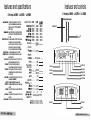
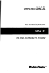
features and specifications
2 ch amp LA-ISS9 LA-23S9 LA-2SS9
•
__ _ _
,_ _ _
c__aency cantral
..II IOnic IInlr lWIb;h
.... bDDIt level control
••lIlDlle
control
,.. ,.... '"pul
h'lh ,.... '"pul
All ... ....
_ I!IJ
!IIIIIOtIII1!IJ
__
,_11111'."
....lkIr Dannlam
IIflm userI willll/OllTlal. fullraJ/{/8 sys/rIm. setfh/s swilr:lJto "FUU'.
"you wish to use /fie inIBma/CfIJSSO\f)(/0 _• dtivefor'I1IJCiflc
frequency""", use /fIe"/.PF"or 7fPF"FOR /fie 'LOWPIISS" OR
HIGHPASS' sem�
fna/i/e5/f1e matdIing 0/input"""Is to /fie otJtpu/_ from _IHIR
(or _ signal svutaI). TIle input sensilivi/y 0/ili/jUs/men/ ranges lrom
6Yto2WTI�
W1IetJ crossover mode selector is in HIGHPASS mode, this COIlIrol sets
the lower frequency limit foraudio prooram sent to tile speakers.
When crossover mode selector is in LOWPASS mode. this control sets
the upper frequency limit for audio pfO(Jram sent to the spea/(BrS.
TtIe crossover is continuously variable adjustment from 40 to 250 HZ.
Ttlis selector switch permits the bass level an increase of 18dB.
Ttlis control permits adjustment o( the bass level up to an 1flCfBiJS8 of
appfDl(imal,1y up to llkJB.
When the sub sonic selector switch is in ·ON· mode, thIs ntter control
perml/s continuously variabl, adjus_t from 10 to 100Hz.
TIIis i6TIfJ fflafures RCA type jacks frJr high impedanc8 input
USB _ willi car sIrirBo output which uses RCA type connec/or cables.
"your cars1etriojacks at. no! RCA type output USB /fie higfl.kJw I,ve{
input adap/rJ( Iv conned /fiespealref otJtpu/ leads 0/carsIrirBo "'" /fie
RCA inputjacks 0/"",.
TIIis "'" _ RCA jacks /orAUXline outputs.Use IfIeS8 for un/imifl>d
SJS/I1m IIIf/IIIIIISiOI1 v the r>JJdAMER/CNI.
TIIis _is ii_in GRfENwhen_is iI/IIlIied.
TIIis _is ii_in RED when /fie lluill-inpm/eCIiOn ciIr:vihy
is acliraled.
TIle fus8pro/ec/s the i1I1¥J/ifier"'"_ car"s ,_ SJS/I1m from sIIo!I
citr:uit condffi0tr3.
Use _ COI1I16Ctofs to deliver_ f}fDIJflI1, "'" """"" fum.on control
Iv IIi8 i6TIfJlfflei:
Tflese lBrmina/s are to ouarantee hlah conductivity and minimum signal loss.
features and controls
2 ch amp LA-ISS9 LA-23S9 LA-2SS9
•
•
IIIJul paw.@IU,DC, 11Hz LA,''''
.".'14_ 1511 W6IJsx2
,.04_ 25IJ W6IJsx2
.".01_ 25IJ W6IJsx2
,.01_
�". ...
",-"..,114...
IfIIIII'ICY rapDnu
•
LA·t311
2OOwmtsx2
lXJwmtsx2
lXJwmtsx2
400wmtsx2
2tXXJ wattsx2
41XXJ wattsx I
lXJ W61Jsx2
1500 W6IJsx2
mJWllJSxl
----
15Hz-3D KHz
lXJwatlsx2
4511 watIsx2
4511 watIsx2
660 watlsx 2
2500 watIsx2
5lXXJ WlIJSxI
sub sonic Ie¥eI comol
---- bas:s l>o0oi level COIirol
---
Input Impedance
,.",.rtI,.
_ SNIIII""
,.""reI;,pm
l1/li mJl/II
t:""'ol ..".,.,,811
__ "/flits
"",.,
... ,.,
--
10K Ohms
(@
---- 200mV-6V Adjustable
>95dB
>65dB
----
40Hz-25OHz
40Hz-250Hz
,.,...,
O-+I&lB
SllII_It:"1W
10-100Hz
atd/If .... ', t'Cf
...... ---- 2-40hms
1It/IfII... ---- 4-8 Ohms
IIIJIJIa _I.
40A
50A
60A
""_"""'" WI".,.
14.4V DC Nell. Ground (ID.5-16V)
dIIIIuIhIIIs (If�H�IJ
.. 213x43x381
iJdII I0.14xl.69xI5
213x43x432
I0.14xl.69xI7
213x43x532
I0.14xl.69x21
��� ®® ®® � ,;) JDll "i" ��O' ���
d
§
j
111__-=
LIN(aUT
R
d
@i
ll
H-alJUl
- .-
I
klw ... inpul>
-----
,-
(@
I
power/protedion LED
low frequeocy control
AUXlire OI.tpul>
higl fTeq,.oncy oorlml
if'llUll""; control
crossoYer mode selector
sub sonice filef swilI:h
��� II!I=�I
-
(@
power terminals
-
(<0
·1.
10
Is
S]
0)
,;,J-�
I�-ml
_ , �_
.
t
•
���
(@
speaker connections
power fuse
LEGAC
merle.
N.
'
A
LEGACY Am.rlun OWIII!!.'S MANUAL · 7
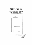
features and specifications
.q ch amp LA-6SS LA-lOSS
features and controls
.q ch amp LA-6SS LA-lOSS
•
..- __•
.. _ _
II7Ien _ with _. full/aI1f/II sys/1lm. set /his"';1!:h ID 'FUll '.
Ifyuu wish to use the inJemaJaDSSINfJIiDfX1M1Iil dtIvet orspecific
"-range. use the 'U'f"1J( 'IIPf" FOR the 1DIII'ASS' DR
HlGHPASS'seJtings.
fnabIeIJ the maI!:hir>g 0{input _ID the ou/puI_ from head/RIa
(or other signalsoon;e). The inputSlJtJSitivity 0{adjustment tangOS from
6VID lYXi71v.
CIIIIIftIr trlll..lnq ClItnII
.... ba... _Iletar
lowl_llnput
hlah I_I Input
lUIlin. lutp""
,...r lID
illMKlloo IS
When crossover mode SIJ/tJCtor is in HIGHP)S5 mode, this control sets
the lower frequency limit tor audio fJflJDraffl sent to tiJ6 speakers,
When crosSOVfJf mode SBifJdor is in LDM'ASS mode, th is control sets
the upperfreqUBncy limittor amiia program sent to th8 sp8akers.
TheCfOSSOYfJ{ is continuously vaJiablea.djustment from 40 to250 HI.
Th is selector switch permits the bass 181/8/ an incrtJaS8 of 18dB.
This amp filalures RCA /yp8jacks for high itnpll(ianc8lnpul.
Uselhese with car sfBreo output which USBS RCA Iyp8 connector cables.
Ifyour cars//iteojacks am n al RCA /yp8 0IJ1pu( the hlg!>-Ia. I,ve/ Input
adaptorID conned the speaker au/pllt leads alcar51efI1o .nd the RCA
Input jacks ofamp.
This amp fBal1Jres RCA jacks torAllX line outputs. USB th8se
ou/puIs Use these tor 1HIlimilBtl sysl8m expanslonlD the flBXIAMERICAN.
Th� indialJrJf � illuminated in GREEN .,." fJOWfIf � app/ifJd.
Th� indialJrJf � illuminated in Rill .,." the buih�n proIedion cirr:u11Ty
tsiIW/aIBd.
__
The fusepro/Iids the """ilierandyrJIIfcats _!ys/J!m from shoJI
ckr;uita>ndltions.
_ _ Use thesecoonedrJr.i ID deli""_ grwnd, andremtJi8funH1n control
ID the """ifllil:
...... _.. ""'" _ "" ID fIIIIlIl1IIe< high ctJfIductivity and minimum signal""
aulliut plIWII@14A1DC,llHz
_". tH _
.@4_
.. ".@1_
.@1_
..... "..,
"".h.It4.,
frequlRCY lespanse
Input Iqllllaice
"""",."
•
LA·'"
50 watts X 4
75 Wattsx4
75 Wattsx4
I(}() Watts X 4
500 Watts X 4
I()(}() Watts X 2
LA·""
I(}() Watts X 4
150 Wattsx4
150 Wattsx4
2(}() Watts X 4
I()(}() Watts X 4
20(}() Wattsx2
----
15Hz-30 KHz
---
IOKohms
-uniIMty
--
1"1 �
'''.'i.'
r@J
---
----
ell 11211lW..,1 i'llUS
---
AUXline IlijlUs
N•
•
A
ch 1/2 aOSSOYer roode selector
en 314 ,,"""'" roode seIecIor
ell 314 bass boosl_
���
i
®®
QlI@ma ®®
@
,��
I
LI"�lIur
L
R
Dlllf� UI
u�,
�
•�
®
�®�
DI
DI Sf4
CH4
---=..J
I
���
r@J
L
powerfprolo:tion LED
ell 314 low 0veI ifllUI>
ell 314 i'llUS 1M! cootr�
ell 112 ifllUI> 1....1 ""'lml
----
���
power fuse
merle.
*=
�IM
power terminals
LEGAC
DIIII
ell 112 bass __
---
"""",,. --- 200mV-6VAdjusfabl.
>95dB
$/II1'IIIi1lll
/I_nel """""'l1li
>65dB
_rei' nltlltl
/til"'"
40Hz-250Hz
40Hz-250Hz
tIP "'"
.. ...,
O/+I8dB
",td,.,,,,..,, ,.,.".
2-4ohms
......
Hi Ohms
.....
8IliIIM AIIIIII nil
3114
5Il4
"",.,.."", WIIIage
14.4V DC Neg. Ground (IO.5-16V)
�1IiIII {WxHI LJ
- 213x43x355
213x43x 432
,... 10]4x1.69x 14
10]4x1.69xI7
----
� f! M
1Ii� .� 1El
.....
-
r@J
:�===�����=�==F�==�==E �==�======
L..
__________
_
speaker connections
LEGACY A.m.rlnn OWIII!!.'S MANUAL · I
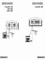
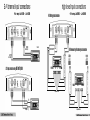
electrical connections
.q ch amp LA-SB9 LA-ICB9
electrical connections
2 ch amp LA-SB9 LA-7B9
LA-9B9 LA-IBB9
LA-23B9 LA-2BB9
•
•
•
•
(@
L...-_
I
e
=
(f)
=
112V
battery
lI!r-mI
��� I���I : -:]11 ��II:-II_���I ���
- - .,.
-
head unit
[0�1
to �more turn-on
+12V
'"
S]I
le G)1 1 2V
�-,--
battery
(@
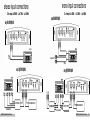
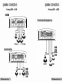
mono Input connections
2 ch amp LA-SSg LA-7S9 LA-9S9
stereo Input connections
2 ch amp LA-SSg LA-7S9 LA-9S9
•
Dalng
•
•
Dalng
low IBVBlinput!l
•
low IBVBlinput!l
head unil
l/R Audio
Oulputs
--1J.;Jfil
.....
To a second amplifier
--------
Y Adaptors
Dalng
high IBVBlinput!l
HlllVEL INPUT AD APTOR
from speaker terminals
LEGACY Am.rlcan OWNEII'S M.MUAL
Dalng
ANOlliERAMERIC ANAMPLIFIER
HlllVEL INPUT AD APTOR
�F:::t t::=t:::3
from speaker tenninals
high IBVBlinput!l
HI LEVELINPUT AD APTOR
t:::C===t-----I
::
ANDlliER AMERICANAMPLIFIER
LEGACY Am.rlun O.tn.'s MANUAL
-
,3;
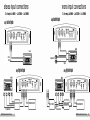
mono Input connections
2 ch amp LA-ISS9 LA-23S9 LA-2SS9
stereo Input connections
2 ch amp LA-ISS9 LA-23S9 LA-2SS9
•
ualna
•
•
ualna
low IBVBlinput!l
•
low IBVBlinputa
head unit
l)R Audio
Outputs
1J.;J§i�
.....
To a ,,",ond amplifier
---------
ualna
Y Adaptors
high IBVBllnput!l
ualna
LEIIEL
high IBVBlinput!l
'.lONe H-WEII
m::J IIIIIIJ Hllal PIllS
� "'. -""'L.. �
..
HI lEVELINPUTADAPTOR
from speaker tenninals
LEGACY Am.rlcan OWNEII'S M.MUAL
...
.. ....
ANOl1iERAMERICANAMPLIFIER
HI lEVEL INPUTAA
D PTOR
�F:::t t::=t:::3
from speaker terminals
HI lEVELINPUT AD APTOR
t::::c:===J--.....
ANOl1iER AMERICANAMPLIFIER
LEGACY Am.rlun O.tn.'s MANUAL
-
'5
2/4 channel Input connections
.q ch amp LA-SSQ LA-IOSQ
•
lJRREAR
AudioOutputs
lJR FRONT
AudioOutputs
2 eN
� eN
head unit
L======::::Ill;J� "g"go.!blo�
Input connections using
low levellnputa
high level Input connections
.q ch amp LA-SSQ LA-IOSQ
•
floating ground connections
HI LEVEL INPUT ADAPTOR
� eN
10iiii¥31
FRONT
L
R
L
R
harness wiring for cammon graund connections
CH3/4
CH1/2
��
��
REAR
1�iiii¥31
REAR L
R
L
from speaker termiRals
Y adaptors
from speaker terminals
R FROIIT
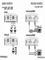
speaker connections
2 ch amp LA-SB9
LA-7B9
LA-9B9
•
LA-IBB9
•
mono Input connections
4 ch amp LA-SB9 LA-ICB9
•
•
LA-23B9
•
LA-2BB9
IKBreo Output made
(@
- - -
��� l�m�1
@
0
s
s
0
I
Bridged mona output mode
(@
��� Imlml
@
Iww-ml
- . ," "
"l}-C'!'
0
s
<
RIGHT speaker
LEFT speaker
s
0
@-�
I
morlea
••
•
A
2 CN mona Input cannectlona ualng
low levellnputa
(@
�II!
.
Imrlll
- • '@ "
���
..-�II!.,
- -
MINIMUM
SPEAKER
IMPEDANCE
4 OHMSI
..., 1.+
low levellnputa
I+
�II!+
< .
I
speaker
LEGAC
���
� CN mana Input connectlonl ullng
(@
LEGACY A.m.rlnn 0 •• 11'1 MANUAL · , ,
speaker connections
.q ch amp LA-6SS LA-lOSS
� CN Output m Ode
� ;;;;:��
���E�5�
�
��
speaker connections
.q ch amp LA-6SS LA-lOSS
•
•
:;;;�
;;;
______
-,-.+
.. .
,-.+ ,-.+
......
L
REAR speakers L
R FRONT speakers
2 CH Btereo Output mode with mono Bridged &ubwoofer Output
(@
- - .,. ,110
S
0
��� I���IIIS
@
@-r:!l'
�II m�
r-ml
Im-!miii
II I
���
�@�.
�',@'�'
Bridged Dual mono Output mode
(@
- - .,.
S]I
0
��� I���I � :]11.-(-Ii
����I ���
���:.-f-_
-I ,+
,-.
.. .
R
speakers
-, I +
,-.
_
(@
MINIMUM
SPEAKER
.. . IMPEDANCE
4 OHMS!
L
I
+
�
SUBWOOFER
(@
MINIMUM
SPEAlER
1M
PEDANCE
'
1+ 4 OHMS!
,-.
.. .L
_
-,-.+
R" •
SPEAKERS
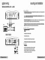
sListem wiring
mounting and Installation
MONO BLOCK AMPLIFIER LA-I.qOO
•
LA-2001D
•
Your new American LEGgarnElifier comes complete with all required mounting hardware. When determining a suitable location in your vehicle for the amp, please remember that
it is a high-power electronic device capable of generating high heat.
==
o
For this reason, alap chaase a lacalian in JIIur vehicle which hIS law libralian,adequale IInliiatian,a minimum aI dust,and na maisture. Be sure to mount
the amp in such a manner as to allow reasonable airtlow over the cooling fins.
Mark the lacatian far the maunling screw hales by positioning the amp where you wish to install it and use a scribe (or one of the mounting screws) inserted in each of the
mounting holes to mark the mounting surtace. If the mounting surtace IS carpeted, measure the hole centers and mark with a felt tip pen.
LJR Audio
head unit
TO SATELLITE
LINE INPUT
Outputs
AMPLIFIER
lefare lIIe.ing ta drill the maunling hales,take nate allIIJ wires,lines ar allier devices in JIIur vehicle which may be lacated behind tile maunting
..rllce! Then drill pilot holes in the mounting surtace for the mounting screws and insert them. Tighten the screws securely.
ta JIIur amplifier, plelSe abserve the
Use at least 8 gauge wire for power and ground connections.
srum aUTrUI ClnIlCTlln
(@
��� ll!!il!!l
@
Wire the amplifier directly to the car battery.
a
IS
.:;
0
-
.:;
I���
�I
'@'
;
-I I
�+
�
»
subwoofer
For the ground connection, use the shortest possible wire to a good chassis ground point.
���
(@
11111111
SPIIIII
IIPmlCI
2-' IIIIS!
American LEGACY Series amplifiers feature built-in fuse systems. These fuses protect both the
amplifier and the electrical system in your vehicle from tault conditions. If you ever need to
replace the fuse in your American LEGACY Series amp, use a fuse of exactly the same type and
rating. A different type or rating of fuse may result in damage or fire.
notes
troubleshooting
liD autput.
p'rotectlon
clrcultru
The built-in protection circuitry in the American
Legacy Series amplifiers will disable the amplifier
if it senses an input overload, a speaker short circuit,
or extreme temperature conditions.
When the protection circuit is activated by any of
these conditions, the Protection LED will be
illuminated.
If this occurs, carefully inspect the system to
determine the source of the problem.
If the shutdown was a result of a thermal overload
condition, allow the amplifier to cool down before
attempting to restart it.
•
If the shutdown was a result of an input overload,
or speaker short circuit, be sure to correct the
condition before restarting.
•
The amplifier can be restarted by turning the remote
power OFF and then ON again.
Confirm that all terminal strip connections are secure and tight.
Check both in-line and built-in fuses. Both the +12Vand the Remote terminals must have +12V referenced to chassis
ground.
Confirm that the audio signal sourca (car radiO, equalizer, etc.) is connected and is supplying output sig nal. To
check if the amp is supplyinQ sig nal, unrlug the cables from th e signal source (but leave them plugged into the
amp). Bnetly tap the center Pin of each 0 the disconnected RCA plugs with yourlinger. This should produca a noise
(teedback) in your speakers.
Only Dne clulnnel works.
Conlirm that all terminal strip connections are secure and tight.
Check the Balance control on the head unit (or other source) to verify that it is set to its midpoint.
If you are using the Low Level RCA input, reverse the input plugs at the amplifier (i.e., switch the L with the R). If
the channels wh ich is silent switches to the other side, the problem is either in the head uniVother source or the
connecting cables.
Welk autp.t.
Readjust the Input Level Control(s) to better suit the input signal.
IIDIse In tile audlD.
If the noise is a ''whine· whose pitch follows the engine speed, confirm that the amplifier and any other signal
sourcas (head unit, etc.) are properly grounded.
If the noise is a "clicking" or ·popping" noise whose rate follows the engine speed, this usually means that the
vehicle is equipped with resistor spark plugs and wires, or that the ignition is in need of service.
Check the rounting of the speaker and input wires to make sure they are not adjacent to wires which interconnect
lights and other accassories.
If the above steps fail to improve or clear noise interterence, the system should be checked by a professional mobile
audio installer.
precautions
Do not operate the amplifier when it is unmounted.
Attach all audio system components securely within
the automobile to prevent damage, especially in an
accident.
Do not mount this amplifier so that the wire
connections are unprotected, or in a pinched
condition, or likely to be darnaged by nearby objects.
Two 4-ohm IPMIt..., wired In PIIr,II,1
lD I bridg.d Iwo-ehlnn.! amplifi.r.
will preHn! • 2-ohm mono loed to th.
amplifi,r. lIOn'TWO-CHANIII!L
AMPUFIIItI DO NOT 1U1'� I-otIM
IIIONO OPERATIONI AIlII'UFER DNMGE
COULD RElILT1
Before making or breaking power connections in
your system, disconnect the vehicle battery. Confirm
that your head unit or other equipment is turned off
while connecting the input jacks and speaker
terminals.
If lOU need to replace the power fuse, do so only
With a fuse identical to that supplied with the amplifier.
Using a fuse of a different type or rating may result
in damage that isn1 covered in the manufacturer�
warranty.
4...ho""oIA..,nn.r
(O,.... nl'nSIo...)
YES!
:t-
Four 4-Ghm ..,e.u" wired In 1It,,-.o,
wli p....m • 4-ohm lo.d 10 ..
ell
chanl'llli 01 1M ampllft.r. Mod four
ChMlMI1 .mpllft.rs will work well In thl'
aanfiguretion.
...."""......." ...,
(O,.,...".
IrIoIl.� 11.,0)
NOI
Four +ohm .pM"''', wired In p ...n.,
10. brldg..:l fuur-d1.nn.l.mpllft.r,
will p....t. • 4..,hm mono lOG til thl
..,pllll.,. MOlT FOUIt-CIlANIilEL
AMP'LFEItI DO NOT"�J.OHM
IIDNO OP'EltAlIONI Mft.l'lEIlIIAMAGIE
COULDalULTI