1
HITACHI INVERTER
J300 SERIES
INSTRUCTION MANUAL
Three phase input 200/400V class
J300 U
: USA version
After reading this manual, keep it at hand for future reference.
Hitachi, Ltd.
Tokyo Japan
NB506XC
SAFETY
For the Best Results with J300 Series inverter, read this manual and all of the warning sign attached to
the inverter carefully before installing and operating it, and follow the instructions exactly. Keep this
manual handy for your quick reference.
Definitions and Symbols
A safety instruction (message) is given with a hazard alert symbol and a signal word;
WARNING or CAUTION. Each signal word has the following meaning throughout this manual.
This symbol means hazardous high voltage. It used to call your attention to
items or operations that could be dangerous to your and other persons operating this equipment.
Read these message and follow these instructions carefully.
This is the “Safety Alert Symbol.” This symbol is used to call your attention
to items or operations that could be dangerous to your or other persons operating this equipment. Read these messages and follow these instructions
carefully.
WARNING WARNING
Indicates a potentially hazardous situation which, if not avoided, can result in
serious injury or death.
CAUTION
CAUTION
Indicates a potentially hazardous situation which, if not avoided, can result in
minor to moderate injury, or serious damage of product.
The matters described under
CAUTION may, if not avoided, lead to
serious results depending on the situation. Important matters are described in
CAUTION (as well as WARNING), so be sure to observe them.
NOTE
NOTE: Notes indicate an area or subject of special merit, emphasizing either
the product’s capabilities or common errors in operation or maintenance.
HAZARDOUS HIGH VOLTAGE
Motor control equipment and electronic controllers are connected to hazardous line voltages. When
servicing drives and electronic controllers, there might be exposed components with cases or protrusions
at or above line potential. Extreme care should be taken to protect against shock.
Stand on an insulating pad and make it a habit to use only one hand when checking components. Always
work with another person in case an emergency occurs. Disconnect power before checking controllers
or performing maintenance. Be sure equipment is properly grounded. Wear safety glasses whenever
working on an electronic controllers or rotating electrical equipment.
-i-
PRECAUTIONS
WARNING: This equipment should be installed, adjusted and serviced by qualified electrical
maintenance personal familiar with the construction and operation of the equipment
and the hazards involved. Failure to observe this precaution could result in bodily injury.
WARNING : The user is responsible for ensuring that all driven machinery, drive train
mechanism not supplied by Hitachi, Ltd., and process line material are capable of safe operation
at an applied frequency of 150% of the maximum selected frequency range to the AC motor.
Failure to do so can result in destruction of equipment and injury to personnel should a single
point failure occur.
WARNING : For protection, install a leak breaker type with a high frequency circuit capable
of large currents to avoid an unnecessary operation. The ground fault protection circuit is not
designed to protect personal injury.
WARNING : HAZARD OF ELECTRICAL SHOCK. DISCONNECT INCOMING
POWER BEFORE WORKING ON THIS CONTROL.
AVERTISSEMENT : RISQUE DE CHOC ELECTRIQUE COUPER L'ALIMENTATION
AVANT LE DEPANNAGE DE CETTE COMMANDE.
WARNING : SEPARATE MOTOR OVERCURRENT, OVERLOAD AND OVERHEATING PROTECTION IS REQUIRED TO BE PROVIDED IN ACCORDANCE
WITH THE SAFETY CODES REQUIRED BY JURISDICTIONAL AUTHORITIES.
AVERTISSEMENT : LE MOTEUR DOIT ETRE MUNI D'UNE PROTECTION
DISTINCTE CONTRE LES SURINTENSITES, LA SURCHARGE ET LA
SURCHAUFFE,CONFORMEMENT AU CODE CANADIEN DE L'ELECTRICITE<
PREMIERE PARTIE.
CAUTION: These instructions should be read and clearly understood before working on J300
series equipment.
CAUTION: Proper grounds, disconnecting devices and other safety devices and their location
are the responsibility of the user and are not provided by Hitachi, Ltd.
CAUTION: Be sure to connect a motor thermal switch or overload device to the J300 series
controller to assure that the inverter will shut down in the event of an overload or an overheated
motor.
CAUTION: DANGEROUS VOLTAGE EXISTS UNTIL CHARGE LIGHT IS OFF.
ATTENTION: PRESENCE DE TENSIONS DANGEREUSES TANT QUE LE VOYANT
N'EST PAS ETEINT.
CAUTION: Rotating shafts and above ground electrical potentials can be hazardous. Therefore, it is strongly recommended that all electrical work conform to the National Electrical Codes
and local regulations. Installation, alignment and maintenance should be performed only by
qualified personnel. Factory recommended test procedures, included in the instruction manual,
should be followed. Always disconnect electrical power before working on the unit.
- ii -
NOTE : POLLUTION DEGREE 2
The inverter must be used in environment of the degree 2.
Typical constructions that reduce the possibility of conductive pollution are;
1) The use of an un-ventilated enclosure
2) The use of a filtered ventilated enclosure when the ventilation is fan forced that is,
ventilation is accomplished by one or more blowers within the enclosure that provide a
positive intake and exhaust.
NOTE : ENCLOSURE SIZE FOR 75 kW TO 110 kW
The inverter, 75kW to 110kW must be installed into an enclosure with dimmensions no
less than 183cm (72 in) by 183cm (72 in) by 60cm (24 in).
NOTE : ENCLOSURE SIZE FOR 132 kW AND BIGGER
The inverters, 132kW and bigger, are complied as recognizedcomponents.
Therse devices are intended for use in an overall ecclosure with an internal ambient of
40 degree C for variable torque rating or 50 degree C for constant torque rating maximum.
End product temperature testing should be conducted to verify sufficient forced air ventilation
is provided to maintain this ambient in room ambient of 10-40 degree C.
Based upon component level testing , end product temperature testing may be conducted at
any convenient room ambient in the rangeof 20-40 dwgree C, unless the room ambient in the
intended application exceeds 40degree C, in which case testing should be conducted at the
elevated ambient.
Enclosure internal ambient temperature should be measured above the drive on to the upper
left or right side. Temperature measurments on the drive itself should not be necessary.
NOTE : SET OF MOTOR CAPACITY AND POLES (A1, A2)
When data does not match a capacity of connected motor , it may cause unstaible motor
operation. Set proper motor capacity (kW) and motor poles even under V/F control mode.
- iii -
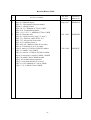
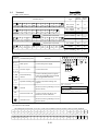
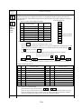
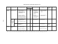
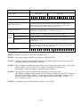
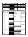
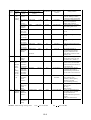
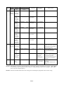
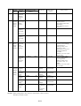
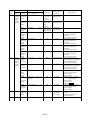
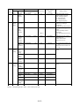
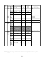
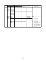
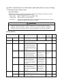
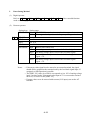
Revision History Table
No.
1
2
3
Revision Contents
Page iii : Pollution degree
Page 2-1 : Description of inverter model
Page4-2 : Change of note
Page 5-8, 5-9 : Addition of 750 to 1100H
Page 5-10 : Terminal description
Page 11-1,11-2,11-3 : addition of 750 to 1100H
Page iii : Enclosure size
Page 4-1 : Enclosure size, page 7-5; note 3,
Page 7-11: F8 boost value in VP1 to 3
Page 7-15: A0 note for boost value
Page 12-13: additio of note 1
Page A25-A31: addition of line for set value
Page A-33: deletion of A-93 on clause
Page iii: note for 132 kW to 220 kW is added
Page 2-1: added 132 to 220kW
Page 4-1; note for 132 kW to 220 kW is added
page 4-2: note,note1 corrected 110kW->260kW
page 5-8: added 1320 to 2200H in table
Page 5-10: terminal layout corrected
Page7-5: corrected monitor d3 39 to 99
Page7-18: A10, addition of 1320 to 2200H
Page 11-1,2,3: added 1320 to 2200H
- iv -
The Date
of Issue
Operation
Manual No.
Aug. 1997
NB506XA
Feb. 1998
NB506XB
Feb. 1999
NB506XC
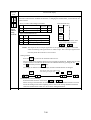
TABLE OF CONTENTS
Page
1.
SAFETY PRECAUTIONS ..........................................................................................
1-1
2.
INSPECTION UPON UNPACKING ........................................................................
2-1
3.
APPEARANCE AND NAMES OF PARTS .............................................................
3-1
4.
INSTALLATION ..........................................................................................................
4-1
5.
WIRING .........................................................................................................................
5-1
6.
OPERATION .................................................................................................................
6-1
7.
OPERATION OF THE DIGITAL OPERATOR ......................................................
7-1
8.
PROTECTION FUNCTIONS .....................................................................................
8-1
9.
TROUBLESHOOTING ...............................................................................................
9-1
10.
MAINTENANCE AND INSPECTION ..................................................................... 10-1
11.
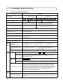
STANDARD SPECIFICATIONS .............................................................................. 11-1
12.
FUNCTIONS WHEN USING THE OPTIONAL REMOTE OPERATOR .......... 12-1
13.
SERVICE ....................................................................................................................... 13-1
APPENDIX 1 ....................................................................................................................... A-1
APPENDIX 2 ....................................................................................................................... A-15
APPENDIX 3 ....................................................................................................................... A-19
APPENDIX 4 ....................................................................................................................... A-20
APPENDIX 5 ....................................................................................................................... A-21
APPENDIX 6 ....................................................................................................................... A-24
APPENDIX 7 ....................................................................................................................... A-25
APPENDIX 8 ....................................................................................................................... A-32
-v-
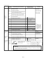
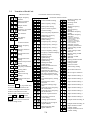
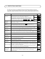
1. SAFETY PRECAUTIONS
1.
Installation
CAUTION
*
*
*
*
*
*
*
*
2.
Be sure to install the unit on flame resistant material such as metal.
............
Otherwise, there is a danger of fire.
Be sure not to place anything inflammable in the vicinity.
...........
Otherwise, there is a danger of fire.
Be sure not to let the foreign matter enter such as cut wire refuse, spatter ...........
from welding, iron refuse, wire, dust, etc.
Otherwise, there is a danger of fire.
Be sure to install it in a place which can bear the weight according to
...........
the specifications in the text (4. Installation).
Otherwise, it may fall and there is a danger of injury.
Be sure to install the unit on a perpendicular wall which is not subject ...........
to vibration.
Otherwise, it may fall and there is a danger of injury.
Be sure not to install and operate an inverter which is damaged or parts ...........
of which are missing.
Otherwise, there is a danger of injury.
Be sure to install it in a room which is not exposed to direct sunlight
...........
and is well ventilated. Avoid environments which tend to be high in
temperature, high in humidity or to have dew condensation, as well as
places with dust, corrosive gas, explosive gas, inflammable gas,
grinding-fluid mist, salt damage, etc.
Otherwise, there is a danger of fire.
Be sure that the wall surface is a nonflammable material, such as steel ...........
plate.
p. 4-1
p. 4-1
p. 4-1
p. 4-1
p. 4-1
p. 4-1
p. 4-1
p. 4-2
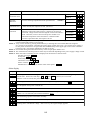
Wiring
WARNING
*
*
*
*
*
Be sure to ground the unit.
Otherwise, there is a danger of electric shock and/or fire.
Wiring work shall be carried out by electrical experts.
Otherwise, there is a danger of electric shock and/or fire.
Implement wiring after checking that the power supply is off.
It might incur electric shock and/or fire.
After installing the main body, carry out wiring.
Otherwise, there is a danger of electric shock and/or injury.
Wait until DC bus voltage is discharged after power supply is turned
off.
Otherwise, there is a danger of electric shock.
1-1
............ p. 5-1
............ p. 5-1
............ p. 5-1
............ p. 5-1
............ p. 5-10
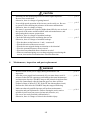
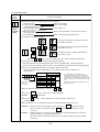
CAUTION
*
*
*
Make sure that the input voltage is:
Three phase 200 to 220 V/50 Hz, 200 to 230 V/60 Hz
Three phase 380 to 415 V/50 Hz, 400 to 460 V/60 Hz
Be sure not to input a single phase to a 3 phase type.
Otherwise, there is a danger of fire.
Be sure not to connect AC power supply to the output terminals
[U (T1), V (T2), W (T3)].
Otherwise, there is a danger of injury and/or fire.
INPUT
OUTPUT
(L1) (L2) (L3)
R
S
T
(T1) (T2) (T3)
U V W
............ p. 5-2
............ p. 5-2
............ p. 5-2
Note)
Power supply
*
*
*
*
*
Fasten the screws with the specified fastening torque. Check so that
there is no loosening of screws.
Otherwise, there is a danger of fire.
Be sure to install an earth leakage breaker.
The ground fault protection is designed to detect current flowing to the
ground upon power on. This function is to protect the inverter, not
people. Install the earth leakage breaker to protect against the ground
fault on wires between the inverter and the motor. (Use a breaker that is
very sensitive to high frequency current so as not to cause malfunction.)
Be sure to set the fuse(s) (the same phase as the main power supply)
in the operation circuit.
Otherwise, there is a danger of fire.
As for motor leads, earth leakage breakers and electromagnetic
contactors, be sure to use the equivalent ones with the specified
capacity (rated).
Otherwise, there is a danger of fire.
Connection to wiring terminal must be reliabily fixed with two means
of support.
1-2
............ p. 5-2
............ p. 5-2
............ p. 5-2
............ p. 5-2
............ p. 5-2
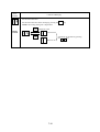
CAUTION
External or remote over load protection required, if multiple motors to
be connected.
............ p. 5-4
For models J300-450LFU and -550LFU only , connect to branch
circuit protected at maximum 300% of output current rating.
Suitable for use on a circuit capable of delivering not more than 10,000
rms symmetrical amperes,*** volts maximum,
(where *** = input voltage)
Alarm connection may contain harzordous live voltage even when
inverter is disconnected. In case of removing front cover for
maintenance or inspection, confirm that incoming power for alarm
connection is surely disconnected.
............ p. 5-11
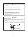
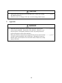
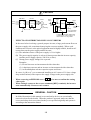
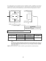
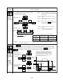
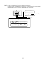
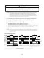
CAUTION
Input phase failure protection
(1) J300-U version inverter are provided with the phase failure protection on the power
supply.
(2) When a buzzer, lamp, noise filter or transformer is connected between the input power
terminals (L1, L2, L3) and input power fuses, input phase failure cannot be protected.
(L1) (L2)
R
S
(L3)
T
L
(Bad example)
Noise filter
Fuse
L
(Good example)
Power supply
1-3
3.
Control and operation
WARNING
*
*
*
*
*
*
*
*
*
Be sure to turn on the input power supply after mounting the surface
cover. While being energized, be sure not to remove the cover.
Otherwise, there is a danger of electric shock.
Be sure not to operate the switches with wet hands.
Otherwise, there is a danger of electric shock.
While the inverter is energized, be sure not to touch the inverter
terminals even during stoppage.
Otherwise, there is a danger of electric shock.
If the re-try mode is selected, it may suddenly restart during the trip
stop. Be sure not to approach the machine. (Be sure to design the
machine so that personnel safety will be secured even if it restarts.)
Otherwise, there is a danger of injury.
Even if the power supply is cut for a short period of time, it may restart
operation after the power supply is recovered if the operation command
is given. If it may incur danger to personnel, be sure to make a circuit
so that it will not restart after power recovery.
Otherwise, there is a danger of injury.
The Stop Key is effective only when the function is set. Be sure to
prepare the Key separately from the emergency stop.
Otherwise, there is a danger of injury.
After the operation command is given, if the alarm reset is conducted, it
will restart suddenly. Be sure to set the alarm reset after checking the
operation command is off.
Otherwise, there is a danger of injury.
Be sure not to touch the inside of the energized inverter or to put a bar
into it.
Otherwise, there is a danger of electric shock and/or fire.
The STOP/RESET key works only when a function is set. Prepare an
emergency switch separately. The use of the STOP/RESET key as an
emergency switch may cause an injury.
1-4
............ p. 6-1
............ p. 6-1
............ p. 6-1
............ p. 6-1
............ p. 6-1
............ p. 6-1
............ p. 6-1
............ p. 6-1
............ p. 7-1
CAUTION
*
*
*
*
4.
Radiating fin and discharging resistor will have high temperature.
Be sure not to touch them.
Otherwise, there is a danger of getting burned.
Low to high speed operation of the inverter can be easily set. Be sure
to operate it after checking the tolerance of the motor and machine.
Otherwise, there is a danger of injury.
If a motor is operated at a frequency higher than 60Hz, be sure to check
the speeds of the motor and the machine with each manufacturer, and
after getting their consent, operate them.
Otherwise, there is a danger of machine breakage.
Check the following before and during the test run.
Otherwise, there is a danger of machine breakage.
• Was the short-cut bar between +1 and + connected?
• Was the direction of the motor correct?
• Was the inverter tripped during acceleration or deceleration?
• Were the rpm and frequency meter correct?
• Were there any abnormal motor vibrations or noise?
• When overcurrent tripping or overvoltage tripping occurs during the
test run, increase the acceleration time or deceleration time.
............ p. 6-2
............ p. 6-2
............ p. 6-2
............ p. 6-3
Maintenance, inspection and part replacement
WARNING
*
*
*
........... p. 10-1
Be sure to turn off the power supply during maintenance and
inspection.
After the power supply has been turned off, you must always wait 10 ........... p. 10-1
minutes so that DC bus capacitors can discharge then start maintenance
and inspection after the CHARGE lamp on the printed-circuit board has
gone out. (Immediately after the lamp has gone out, there will be a
residual voltage of about 50 V DC in the DC bus intermediate circuit.)
Perform the work after the CHARGE lamp has stopped flickering.
Make sure that only qualified persons will perform maintenance,
........... p. 10-1
inspection and part replacement. (Before starting the work, remove
metallic objects from your person (wristwatch, bracelet, etc.)
(Be sure to use tools protected with insulation.)
Otherwise, there is a danger of electric shock and/or injury.
1-5
CAUTION
*
5.
........... p. 10-1
When removing connectors, never pull the wires. (Wires for cooling
fan and thermal relay)
Otherwise, there is a danger of fire due to wire breakage and/or injury.
Appendix
WARNING
*
*
........... p. A-15
When the inverter stops due to a trip with retry mode selected, the
motor restarts suddenly. Stand clear of the machine. Otherwise, you
may be injured. (Design the machine in such a way that persons are
protected against a restart of the machine.)
If the retry mode is selected, do not approach the inverter unnecessarily. ........... p. A-16
It will be restarted suddenly after it trips/stops. (Design the inverter so
that the safety can be assured even in such a restart.) Otherwise, bodily
injury will result.
1-6
Others
WARNING
*
Never modify the unit.
Otherwise, there is a danger of electric shock and/or injury.
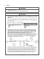
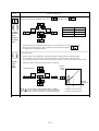
CAUTION
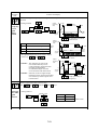
*
Withstand voltage tests and insulation resistance tests (megger tests) are executed
before the units are shipped, so that there is no need to conduct these tests before
operation.
When conducting megger tests as a part of daily inspection, be sure that these tests are
only executed between the main circuit and the ground. Do not execute megger tests
on the control circuit.
(L1) (L2) (L3) (RB) (+)
R
S
T RB
P
(–) (T1) (T2) (T3)
N
U
V W
FM
Megohm-meter
*
P24
PLC
FW
•••
Megohm-meter
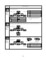
Do not attach or remove wiring or connectors (including Digital operator and
Remote operator) when power is applied. Also, do not check signals during
operation. Otherwise, a trip may occur or a failure may be caused. To stop the
operation, be sure to use an operation instruction (FW,REV.) Do not turn
power off within three minutes after it is turned on, or vice versa.
Do not stop operation by switching off the electromagnetic(Mgo) contactors on
the primary or secondary sides of the inverter.To stop the operation, be sure to
use an operation instruction (FW,REV.) Do not turn power off within three
minutes after it is turned on, or vice versa.
(Bad example)
ON,OFF
➤
Power
supply
➤
Earth
leakage
breaker
Mgo
➤
*
➤
6.
(L1) (L2) (L3)
R, S, T
(T1) (T2) (T3)
U, V, W
Motor
FW
INV
ON,OFF
➤
PV24
Turn ON and OFF
(Good example)
When there has been an instantaneous power failure, and if an operation instruction
has been given, then the unit may restart operation after the power failure has ended. If
there is a possibility that such an occurrence may harm humans, then install an
electromagnetic contactor (Mgo) on the power supply side, so that the circuit does not
allow automatic restarting after the power supply recovers. If the optional remote
operator is used and the retry function has been selected, this will also cause automatic
restarting when an operation instruction has been input, so please be careful.
1-7
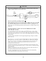
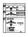
CAUTION
*
Do not insert leading power factor capacitors or surge absorbers between the
output terminals of the inverter and the motor.
Earth
leakage
breaker
Power
supply
Surge absorber
(L1) (L2) (L3)
R, S, T,
INV
(T1) (T2) (T3)
U, V, W,
Motor
Leading power factor capacitor
*
*
Be sure to ground the grounding terminal,
.
When inspecting the unit, after turning the power supply off be sure to wait unitl
the CHARGE lamp beside the control terminal is off before opening the cover.
(If the lamp is lit or still flickering, then the internal capacitor’s residual voltage is still
dangerous.)
*
MOTOR TERMINAL SURGE VOLTAGE SUPPRESSION FILTER
(FOR THE 400 V CLASS)
In a system using an inverter of the voltage control PWM system, a surge voltage
caused by the cable constants such as the cable length (especially when the distance
between the motor and inverter is 10 m or more) and cabling method may occur at the
motor terminal.
A dedicated filter of the 400 V class for suppressing this surge voltage is available,
Please order one.
*
PROTECTION AGAINST NOISE INTERFERENCE FROM INVERTER
The inverter uses many semiconductor switching elements such as transistors and
IGBTs. Thus, a radio set or measuring instrument located near the inverter is
susceptible to noise interference.
To protect the instruments from erroneous operation due to noise interference, they
should be installed well apart from the inverter. It is also effective to shield the whole
inverter structure.
Addition of an EMI filter on the input side of the inverter also reduces the effect of
noise from commercial power line on external devices.
Note that external dispersion of noise from the power line can be minimized by
connecting an EMI filter on the primary side of inverter.
1-8
CAUTION
Inverter
L1(L1) U (T1) U
L2(L2) V (T2) V
L3(L3) W (T3) W
Power
source
Motor
Terminal
for
grounding
EMI
filter
Noise
Motor
➤
R2
S2
T2
Inverter
➤
Power
source
R1
S1
T1
Ground the
frame.
➤
Remote
operator
EMI filter
Noise
Piping
(to be grounded)
or shielded wire
Completely ground the shield made
of metal screen, enclosed panel, etc.
with as short a wire as possible.
*
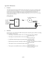
EFFECTS OF DISTRIBUTOR LINES ON INVERTERS
In the cases below involving a general-purpose inverter, a large peak current flows on
the power supply side, sometimes destroying the converter module. Where such
situations are foreseen, or the paired equipment must be highly reliable, install an AC
reactor between the power supply and the inverter.
(A) The unbalance factor of the power supply is 3% or higher.
(B) The power supply capacity is at least 10 times greater than the inverter capacity
(and the power supply capacity, 500 kVA or more).
(C) Abrupt power supply changes are expected.
Examples:
(1) Several inverters are interconnected with a short bus.
(2) A thyristor converter and an inverter are interconnected with a short bus.
(3) An installed phase advance capacitor opens and closes.
In cases (A), (B) or (C), we recommend installing an AC reactor of 3% (in a voltage
drop at rated current) with respect to the supply voltage on the power supply side.
*
*
When occurring an EEPROM error (
), be sure to confirm the setting
value again.
When setting b contact to the reverse command ([REV] terminal), the inverter
state automatically. Do not set to b contact.
GENERAL CAUTION
In all the illustrations in this manual, covers and safety devices are occasionally
removed to describe the details. When the product is operated, make sure that the
covers and safety devices are placed as they were specified originally and operate it
according to the instruction manual.
1-9
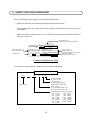
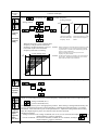
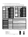
2. INSPECTION UPON UNPACKING
Before installation and wiring, be sure to check the following:
•
Make sure that there was no damage during transportation the unit.
•
After unpacking the unit, make sure that the package contains one inverter and one operation manual
•
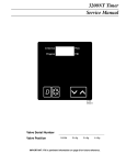
Make sure that the product is the one you ordered by checking the specifications label on
the front of the cover.
Model abbreviation
(The example is for the J300-055HFE2)
HITACHI
INVERTER
055HFU
J300
Input power supply,
phase, and frequency
INPUT
380-415V 3 Ph 50 Hz
400-460V 3 Ph 60 Hz
Production year
DATE 1995
OUTPUT
max:380-460V 3 Ph
Amps (CT) 13 A/(VT) 16 A
(CT) 5.5kW(VT) 7.5kW
MFG. NO. J300U-055H251L
Hitachi, Ltd.
Made in Japan
NE15390
Output voltage
Rated output current
Maximum applicable motor (4P kW)
Production number
and factory control symbol
Contents of Specifications Label
If you discover any problems, contact your sales agent immediately.
Description of Inverter Model
J300
055
H
F
U
Version number
U : USA version
Structure type
F: with digital operator
(Semi-closed, open type)
Series name
Input voltage
L : Three phase 200V class
H : Three phase 400V class
Applicable motor capacity (4P.kW)
055: 5.5 kW
550: 55 kW
075: 7.5 kW
750: 75 kW
110: 11 kW
900: 90kW
150: 15 kW
1100: 110 kW
220: 22 kW
1320: 132 kW
300: 30 kW
1600: 160kW
370: 37 kW
2200: 220 kW
450: 45 kW
2-1
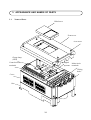
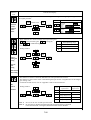
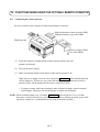
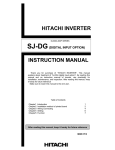
3. APPEARANCE AND NAMES OF PARTS
3.1
Names of Parts
Blind cover
Front cover
A set screw
Charge lamp
(LED)
Control circuit
terminals
Digital
operator
Main circuit
terminals
Wiring
holes
Cover
Case
3-1
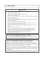
4. INSTALLATION
CAUTION
*
*
*
*
*
*
*
Be sure to install the unit on flame resistant material such as metal.
Otherwise, there is a danger of fire.
Be sure not to place anything inflammable in the vicinity.
Otherwise, there is a danger of fire.
Be sure not to let the foreign matter enter such as cut wire refuse, spatter from welding,
iron refuse, wire, dust, etc.
Otherwise, there is a danger of fire.
Be sure to install it in a place which can bear the weight according to the specifications
in the text (4. Installation).
Otherwise, it may fall and there is a danger of injury.
Be sure to install the unit on a perpendicular wall which is not subject to vibration.
Otherwise, it may fall and there is a danger of injury.
Be sure not to install and operate an inverter which is damaged or parts of which are
missing.
Otherwise, there is a danger of injury.
Be sure to install it in a room which is not exposed to direct sunlight and is well
ventilated. Avoid environments which tend to be high in temperature, high in
humidity or to have dew condensation, as well as places with dust, corrosive gas,
explosive gas, inflammable gas, grinding-fluid mist, salt damage, etc.
Otherwise, there is a danger of fire.
NOTE : ENCLOSURE SIZE FOR 75 kW to 110kW
The inverters, 75kW to 110kW must be installed into an enclosure with dimmensions no
less than 183cm (72 in) by 183cm (72 in) by 60cm (24 in).
NOTE : ENCLOSURE SIZE FOR 132 kW AND BIGGER
The inverters, 132kW and bigger, are complied as recognizedcomponents.
Therse devices are intended for use in an overall ecclosure with an internal ambient of
40 degree C for variable torque rating or 50 degree C for constant torque rating maximum.
End product temperature testing should be conducted to verify sufficient forced air ventilation
is provided to maintain this ambient in room ambient of 10-40 degree C.
Based upon component level testing , end product temperature testing may be conducted at
any convenient room ambient in the rangeof 20-40 dwgree C, unless the room ambient in the
intended application exceeds 40degree C, in which case testing should be conducted at the
elevated ambient.
Enclosure internal ambient temperature should be measured above the drive on to the upper
left or right side. Temperature measurments on the drive itself should not be necessary.
4-1
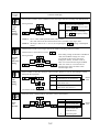
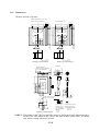
➤
For cooling purposes, be sure that the inverter is installed vertically. In addition, be sure that it
is separated from other components and walls. If foreign matter is introduced into the interior
of the inverter, this may cause malfunctions, so make sure that no foreign matter can enter it.
Flow of air
➤
➤
10 cm or more
(30cm or more)
5 cm
5 cm
➤ or
➤
➤ or
Wall ➤
➤
more
➤
➤
more
10 cm or more
(30cm or more)
(a)
(b)
NOTE: Install the inverter vertically.
Do not install it on the floor or horizontally.
( ) is for 75 to 260kW
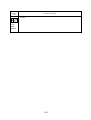
CAUTION
Be sure that the wall surface is a nonflammable
material, such as steel plate.
Be sure to check the ambient temperature.
Place of installation
Within the enclosure
(NOTE 1)
Load characteristics
Constant torque
Variable torque
Ambient temperature
-10 to 50°C
-10 to 40°C
Applicable model
All models
(NOTE 2)
NOTE 1: The inverter should be installed in a locked enclosure that meets the requirements in
IP4X.
The higher the ambient temperature inside the inverter, the shorter its life will be. If
a heat generating unit is used near the inverter, try to keep it as far away as possible.
Also, when installing the inverter in a box, be sure to carefully consider ventilation
and the dimensions.
NOTE 2: Each of inverters 22 kW to 260 kW must be installed in a locked enclosure.
4-2
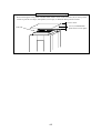
Precaution for installation and wiring
➤
When executing the wiring work or another work, attach a cover on the vent hole (slit) on the top of the
inverter to prevent wire chips, weld spatters, iron scraps, or dust from falling into the inverter.
➤
Vent hole
➤
➤
4-3
15 cm or more
Cover (a nonflammable
plate such as an iron plate)
5. WIRING
WARNING
* Be sure to ground the unit.
Otherwise, there is a danger of electric shock and/or fire.
* Wiring work shall be carried out by electrical experts.
Otherwise, there is a danger of electric shock and/or fire.
* Implement wiring after checking that the power supply is off.
It might incur electric shock and/or fire.
* After installing the main body, carry out wiring.
Otherwise, there is a danger of electric shock and/or injury.
5-1
CAUTION
* Make sure that the input voltage is:
Three phase 200 to 220 V/50 Hz, 200 to 230 V/60 Hz
Three phase 380 to 415 V/50 Hz, 400 to 460 V/60 Hz
* Be sure not to input a single phase to a 3 phase type.
Otherwise, there is a danger of fire.
* Be sure not to connect AC power supply to the output terminals
[U (T1), V (T2), W (T3)].
Otherwise, there is a danger of injury and/or fire.
INPUT
OUTPUT
(L1) (L2) (L3)
R
S
T
(T1) (T2) (T3)
U V W
Note)
Power supply
* Fasten the screws with the specified fastening torque. Check so that there is no
loosening of screws.
Otherwise, there is a danger of fire.
Be sure to install an earth leakage breaker.
* The ground fault protection is designed to detect current flowing to the ground upon
power on. This function is to protect the inverter,not people. Install the earth leakage
breaker to protect against the ground fault on wires between the inverter and the motor.
(Use a breaker that is very sensitive to high frequency current so as not to cause
malfunction.)
* Be sure to set the fuse(s) (the same phase as the main power supply)
in the operation circuit.
Otherwise, there is a danger of fire.
As for motor leads, earth leakage breakers and electromagnetic contactors, be sure to
use the equivalent ones with the specified capacity (rated).
Otherwise, there is a danger of fire.
5-2
The terminal board will be exposed when the front cover or terminal cover (450L/HF,
550L/HF) is removed. Wire the inverter in this state.
5.1
Wiring the Power Supply and Motor
G
(PE)
R
(L1)
S
(L2)
T
(L3)
RB
(RB)
P
(+)
N
(-)
U
(T1)
V
(T2)
W
G
(T3) (PE)
MOTOR
Dynamic
braking
resistor
Braking Units
ELB
Power supply
• The inverter will be damaged if the power supply is connected to the motor terminals
U(T1), V(T2) and W(T3), so be sure not to make any mistakes.
• If multiple motors are to be connected, be sure to attach a thermal relay to each motor.
NOTE 1: When changing the power supply of the motor between the inverter and commercial power, be sure to install mechanically interlocked switches Mg1 and Mg2.
Mg1
ELB
Power
supply
Mg0
R (L1)
S (L2)
T (L3)
(T1) U
Inverter (T2) V
(T3) W
Motor
Mg2
NOTE 2: Install an earth leakage breaker at the input of the inverter. (Select an earth leakage breaker whose sensitive current level is raised in high frequency range.)
When the cable length between the inverter and motor is long (more than 10 m),
the thermal relay may malfunction due to higher harmonics. Therefore, install an
AC reactor on the output side of the inverter or use a current sensor in place of the
thermal relay.
5-3
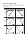
NOTE 3: Be sure that the specified grounding is carried out. Be sure to separate the unit’s
grounding pole from those of other heavy electric machinery, and avoid using
common grounding poles.
If multiple inverters are used, make sure that the grounding connections do not
create a loop.
Improper grounding
Proper grounding
Inverter
Inverter
Inverter
Inverter
Inverter
Inverter
Grounding bolt
(at the site)
CAUTION
External or remote over load protection required, if multiple motors to be connected.
For models J300-450LFU and -550LFU only , connect to branch circuit protected at
maximum 300% of output current rating.
Suitable for use on a circuit capable of delivering not more than 10,000 rms
symmetrical amperes,*** volts maximum,
(where *** = input voltage)
5-4
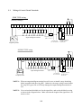
5.2
Wiring of Control Circuit Terminals
SINK TYPE wiring
(Factory settings)
FM CM1 PLC P24 FW
8
7
6
5
4
3
2
1
H
O
OI
L CM2 12
11
AL2 AL1 AL0
RY
RY
Fault alarm
Frequency setting
(500 Ω to 2 kΩ)
Input intelligent terminal
Current input
DC 4 to 20 mA
Frequency meter
For output
Intelligent terminal
27 VDC 50 mA
50 mA max
SOURCE TYPE wiring
FM CM1 PLC P24 FW
8
7
6
5
4
3
2
1
H
O
OI
L CM2 12
11
AL2 AL1 AL0
RY
RY
Input intelligent terminal
Frequency setting
(500 Ω to 2 kΩ)
Current input
DC 4 to 20 mA
Frequency meter
Fault alarm
For output
Intelligent terminal
27 VDC 50 mA
50 mA max
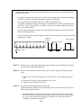
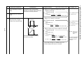
NOTE 1: When an output intelligent terminal is used, be sure to install a surge absorbing
diode in parallel with the relay (RY). Otherwise, the surge voltage created when
the relay (RY) goes ON or OFF may damage the output intelligent terminal circuit.
NOTE 2: Use a twisted and shielded wire for the signal line, and cut the shielded covering
as shown in the diagram below. Make sure that the length of the signal line is 20
meters or less.
5-5
Insulate
➤
➤
➤
No grounding necessary
Connect FG (frame ground) of the inverter.
➤
NOTE 3: When the frequency setting signal is turned on and off with a contact, use a relay
which will not cause contact malfunctions, even with the extremely weak currents
and voltages, such as crossbar twin contacts, etc.
NOTE 4: Use relays which do not have contact defects at 24 V DC, 3 mA for the other
terminals.
NOTE 5: Separate the main circuit wiring from the relay control circuit wiring. If they must
cross, be sure that they cross at a right angle.
Main circuit power line
(R, S, T, U, V, W, PP, P, RB, N, L1, L2, L3, T1, T2, T3, +, -, etc.)
➤
Right angle
➤
Signal input line
(FM, CM1, PLC, P24, FW, 8, 7, 6, 5, 4, 3, 2, 1,
➤ ➤
H, O, OI, L, CM2, 12, 11, AL0, AL1, AL2)
Separate by 10 cm or more.
➤
NOTE 6: Do not short between the terminals H and L and between the terminals P24 and
CM1 of the control circuit.
NOTE 7: Insulate the common terminal L for frequency analog command input and the
common terminal (COMMON) of the peripheral equipment such as the sequencer
before starting use.
5-6
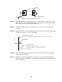
5.3
Connection to the Programmable Controller
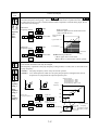
(1) When the internal interface power source is used
① This is an example when the sink type transistor
output (open collector output) module of the
sequencer is connected
Note: Make sure of the short-circuit bar or wire
between the terminals PLC and P24.
J300 series
S
P24
CM1
PLC
1
② This is an example when the source type
transistor output (open collector output)
module of the sequencer is connected
Note: Make sure of the short-circuit bar or wire
between the terminals CM1 and PLC.
J300 series
COM
+
P24
CM1
PLC
24V DC
1
FW
8
2
8
8
2
8
2
9
1
9
1
COM
S
Inverter
YTR48 type output module
(by Hitachi)
+
② This is an example when the source type
transistor output (open collector output)
module of the sequencer is connected
Note: Remove the short-circuit bar or wire between
the terminals CM1 and PLC or P24 and PLC.
J300 series
24V DC
-
Inverter
YTS48 type output module
(by Hitachi)
(2) When the external interface power source is used
① This is an example when the sink type transistor
output (open collector output) module of the
sequencer is connected
Note: Remove the short-circuit bar or wire between
the terminals CM1 and PLC or P24 and PLC.
1
24V DC
-
FW
2
S
+
P24
CM1
PLC
J300 series
COM
+
-
24V DC
+
-
1
FW
24V DC
P24
CM1
PLC
FW
2
8
2
8
8
2
8
2
9
1
9
1
COM
S
Inverter
Inverter
YTR48 type output module
YTS48 type output module
(by Hitachi)
(by Hitachi)
Note: Be sure to turn the inverter on after the controller and external power source are turned on.
(Otherwise, the data in the inverter may be changed.)
5-7
+
24V DC
-
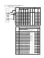
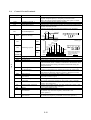
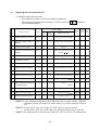
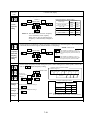
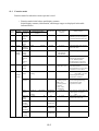
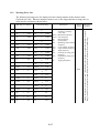
5.4
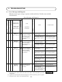
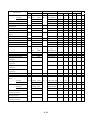
Wiring Equipment, Options (EMI filter, etc.)
Standard equipment
(200V class)
Applicable equipment
Wiring (AWG or Kcmil)
Constant torqe
Inverter
model
Power supply
Variable torqe
Motor Power
Motor Power
output lines
output lines
(kW) R,S,T,U,V (kW) R,S,T,U,V RB1,2,3,
W,P,N
➤
➤
ELB
Magnetic
contactor ➤
Power
Signal Signal Earth leakage Electrolines
lines
lines
breaker (ELB) magnetic
External FM,CM1,PCL P24,AL0,AL1
contactor
resistor FW,8,7,6,5,4,3 AL2
J300-055LF
5.5
J300-075LF
7.5
J300-110LF
11
J300-150LF
15
J300-220LF
22
J300-300LF
30
J300-370LF
37
J300-450LF
45
AWG 8
or more
AWG 6
or more
AWG 4
or more
AWG 3
or more
AWG 1/0
or more
AWG 3/0
or more
AWG 4/0
or more
300
or more
J300-550LF
55
350
or more
W,P,N
7.5
11
15
22
30
37
45
55
75
P,RB
2,1,H,O,OL,L,
CM2,12,11
AWG 18
AWG 16
AWG 8 10
or more or more Shielded or more
AWG 6
wire
10
or more or more
AWG 4
or more
When the
number of
AWG 3
shielded
or more
wires to be
used is 11
AWG 1/0
or more,
or more
the section
AWG 3/0
of each
shielded
or more
wire
AWG 4/0
should be
AWG 20
or more
300
or more
350
or more
EX50C(30A)
H20
EX50C(30A)
H20
EX50C(50A)
H25
EX60B(60A)
H35
RX100(75A)
H50
RX100(100A) H65
RX100(100A) H80
RX225(150A) H100
RX225(175A) H125
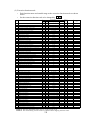
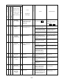
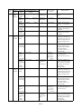
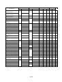
(400V class)
Applicable equipment
Wiring
Inverter
model
Constant torqe
Variable torqe
Power
Signal Signal Earth leakage Electrolines
lines
lines
breaker (ELB) magnetic
External FM,CM1,PCL P24,AL0,AL1
contactor
resistor FW,8,7,6,5,4,3 AL2
Motor Power
Motor Power
output lines
output lines
(kW) R,S,T,U,V (kW) R,S,T,U,V RB1,2,3,
W,P,N
J300-055HF
5.5
J300-075HF
7.5
J300-110HF
11
J300-150HF
15
J300-220HF
22
J300-300HF
30
J300-370HF
37
J300-450HF
45
J300-550HF
55
J300-750HF
75
AWG 8
or more
AWG 8
or more
AWG 8
or more
AWG 6
or more
AWG 4
or more
AWG 4
or more
AWG 2
or more
AWG 1
or more
AWG 3/0
or more
300
or more
J300-900HF
90
J300-1100HF
W,P,N
7.5
11
15
22
30
37
45
55
75
P,RB
2,1,H,O,OL,L,
CM2,12,11
AWG 8
10
AWG 18
AWG 16
or more or more Shielded or more
AWG 8
wire
10
or more or more
AWG 8
When the
or more
number of
AWG 6
shielded
or more
wires to be
used is 11
AWG 4
or more,
or more
the section
AWG 4
of each
shielded
or more
wire
AWG 2
should be
AWG 20.
or more
AWG 1
or more
AWG 3/0
or more
EX50C(30A)
H20
EX50C(30A)
H20
EX50C(50A)
H25
EX60B(60A)
H35
RX100(75A)
H50
RX100(100A) H65
RX100(100A) H80
RX225(150A) H100
RX225(175A) H125
90
300
or more
RX225(225A) H150
300
or more
110
300
or more
RX225(250A) H220
110
350
or more
132
350
or more
RX400(350A) H250
J300-1320HF
132
AWG 4 / 0
parallel
160
AWG 4 / 0
parallel
RX400(400A)
H400
J300-1600HF
160
300
parallel
220
300
parallel
RX600(600A)
H600
J300-2200HF
220
350
parallel
260
350
parallel
RX600(600A)
H600
5-8
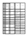
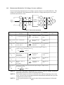
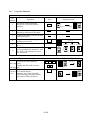
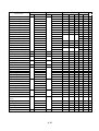
Part description
➤
➤
➤
R
S
T
(L1) (L2) (L3)
(+) P
Function
AC reactor for
improving
the power factor
(ALIL)
(ALIH)
This part is used when the unbalance voltage ratio is 3%
or more and power supply is 500 kVA or more, and there
is a rapid change in the power supply.
It also improves the power factor.
Radio noise filter
(Zero phase
reactor) (ZCL-A)
Using the inverter may cause noise on the peripheral
equipment through the power lines.
This part reduces noise.
EMI filter for
inverter
(FFJ300-
This part reduces common noise generated between
the power supply and the ground, as well as normal noise.
Put it in the primary side of inverter.
)
➤
Inverter
Regenerative
resistor
(RB
-
RB
(T1) (T2) (T3)
U
V W
➤
This part is used for applications that needs to increase
the brake torque of the inverter or to frequently turn on
and off and to run high inertia load.
)
Radio noise filter
(Zero phase
reactor) (ZCL-A)
This part reduces noise generated at the output of
the inverter.
(It is possible to use for both input and output.)
AC reactor for
reducing vibration
(ACL-L)
(ACL-H)
Running motors with the inverter generates vibration
greater than that with commercial power supply.
This part installed between the inverter and motor reduces
torque ripple.
When the cable length between the inverter and motor is
long, a countermeasure for a malfunction of the termal
relay is taken.
➤
Thermal
relay
IM
Motor
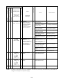
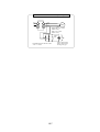
NOTE
NOTE
NOTE
NOTE
1:
2:
3:
4:
The applicable equipment is for Hitachi standard four pole squirrel-cage motor
Be sure to consider the capacity of the circuit breaker to be used.
Be sure to use bigger wires for power lines if the distance exceeds 20m.
Be sure to use an grounding wire same size of power line or similar.
(*) Use AWG 16 wire for the alarm signal wire.
Classify the detective current of the earth leakage breaker depending on the total
distance between the inverter and the motor.
Detective current (mA)
length
100 m and less
30
300 m and less
100
600 m and less
200
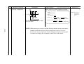
NOTE 5: When using CV wire and metal tube,
the leakage current is around 30 mA/km.
NOTE 6: The leakage current becomes eight times
because IV wires have a high dielectric
constant. Therefore, use an one class
larger earth leakage breaker according
to the left table.
5-9
Terminal
➤
5.5
➤
Width
(1) Main circuit terminal
Terminal layout
R
G
(PE) (L1)
S
(L2)
RB
T
(L3) (RB)
P
(+)
N
(Ð)
U
(T1)
V
(T1)
W
(T1)
R
G
(PE) (L1)
S
(L2)
T
(L3)
N
(Ð)
U
(T1)
V
(T1)
W
(T1)
G
(PE)
G
(PE)
G
(PE)
R
(L1)
R
(L1)
S
(L2)
T
(L3)
S
(L2)
T
(L3)
P
(+)
,,,,
,,,,
PD
(+1)
P
(+)
,,,,
,,,,
PD
(+1)
P
(+)
Screw Width
diameter (mm)
Type
G
(PE)
M5
13
M6
17.5
M8
M10
23
35
220 to 370HF
M6
17.5
450, 550HF
M8
23
750, 900HF
M10
35
1100HF
M10
40
1320 to 2200HF
M16
51
Internal short circuit bar
N
(Ð)
U
(T1)
V
(T1)
055, 075LF
055,075HF
011, 150LF
011, 150HF
220 to 370LF
450, 550LF
G
(PE)
W
(T1)
Internal short circuit bar
N
(Ð)
U
(T1)
V
(T1)
G
(PE)
W
(T1)
Main circuit
Terminal
symbol
R, S, T
(L1),(L2),(L3)
U, V, W
RB
R
(RB) (L1)
Function
Terminal description
Main power
Connect the power supply
Inverter output
Connect the motor
P, RB
P, N
(+),(-)
G
P
(+)
N
(-)
U
V
(T1) (T2)
W
G
(T3) (PE)
MOTOR
Braking Units
ELB
Power supply
External braking
resistor
,,,
* Only the 055LF/HF and 075LF/HF
are equipped RB terminals .
Dynamic braking unit Connect a dynamic braking unit
(option)
Internal short circuit bar
PD
(+1)
P
(+)
DCL
Remove the internal short circuit bar when
DCL is connected.
Ground (connect grounding to avoid
electric shock)
(PE)
PD
PD
(+1)
DCL
Connect a braking resistor (option)
Ground
(+1)
T
(L3)
Braking
resistor
(T1),(T2),(T3)
(+),(RB)
S
(L2)
External choke coil
Connect a choke coil (DCL) for
harmonics current reduction
Ground at case
Ground (connect grounding to avoid
electric shock)
WARNING
Wait until DC bus voltage is discharged after power
supply is turned off.
Otherwise, there is a danger of electric shock.
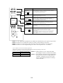
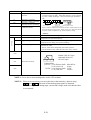
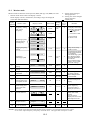
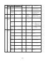
(2) Control circuit terminal
The intelligent I/O terminals 1 to 8 and 11 and 12 are initialized as shown below at factory before shipment.
FM CM1 PLC P24 FW REV CF1 USP CH1 FRS
FM CM1 PLC P24 FW
JG
AT
RS
↑
↑
↑
↑
↑
↑
↑
↑
8
7
6
5
4
3
2
1
5-10
H
H
O
O
OI
OI
L
L
CM2 RUN FA1
↑
↑
CM2 12
11
AL2 AL1 AL0
AL2 AL1 AL0
Control circuit
Terminal
symbol
Input
monitor
signal
Frequency
command
input
Output
signal
Standard setting of
intelligent terminal
Terminal description and function
FM
Frequency monitor
CM1
Common for monitor
PLC
Common terminal for the external power
source of the sequencer (PLC)
Remarks
Dry contact
Close: ON (run)
Open: OFF (stop)
Min. ON time:
20 ms or more
P24
Internal power source for the frequency
monitor and intelligent input terminal
FW
Forward operation
8
Intelligent input terminal 8
REV Reverse operation
7
Intelligent input terminal 7
6
Intelligent input terminal 6
CF1 Multistage speed
(First stage)
USP Prevention function of
restart upon power on.
5
Intelligent input terminal 5
CH1 2 stage acc./dec.
4
Intelligent input terminal 4
FRS Free run input signal
3
Intelligent input terminal 3
JG
Jogging
2
Intelligent input terminal 2
AT
Current input selection
1
Intelligent input terminal 1
RS
Reset
H
Power supply for frequency command
10 VDC
O
Voltage frequency command
OI
Current frequency command
0-5 VDC (nominal), 0-10 VDC
(nominal)(Input impedance 30 kΩ)
DC 4-20 mA (nominal)
Input impedance 250Ω
L
Common for frequency command
CM2
Common for intelligent output terminal
12
Intelligent output signal 12
RUN Run signal
11
Intelligent output signal 11
FA1
Fault alarm AL0
output
AL1
AL2
AL2 AL1 AL0
Normal: AL0-AL1 close
Abnormal, Power off:
AL0-AL1 open
Note:
If the power is turned
on when the input
terminals 1 to 5 are
kept on, all the data
stored in the inverter
is initialized.
Therefore, never turn
the power on in such
a state.
(NOTE 1)
Frequency arrival signal
27 VDC
50 mA max
Contact rating
250 VAC 2.5 A (Resistor load)
0.2 A (cos¿=0.4)
30 VDC 3.0 A (Resistor load)
0.7 A (cos¿=0.4)
Min 100 VAC
10 mA
5 VDC
100 mA
CAUTION
Alarm connection may contain hazardous live voltage even when inverter is disconnected.
In case of removing flont cover for maintenance or inspection, confirm that incoming power
for alarm connection is surely disconnected.
NOTE1: Terminal RS can use only contact a (normally open). It cannot use contact b (normally closed).
5-11
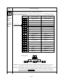
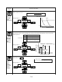
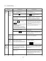
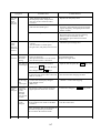
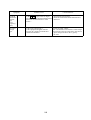
5.6
Control Circuit Terminals
Terminal symbol
FM
Terminal name
Monitor terminal
CM1
PLC
P24
Common terminal 1
Internalinterfacecommon
Inputsignalpowersource
FW
Forwardrun/stopterminal
REV
1 to 8
CF3
(NOTE 1)
JG
DB
STN
SET
CH1
FRS
EXT
USP
Forward
Reverse
Reverse run/stop
CF1
CF2
Description
Analog: Output frequency, current, torque
Digital: Output frequency x frequency converted value
(Set in the remote operator monitor mode), max. pulse: 3.6 kHz
Common terminal for the monitor terminal
Common terminal for the external power source of the sequencer
Internal power source for the contact input terminal and frequency
monitor terminal, 24 VDC.
Common for the FW terminal and intelligent input terminals
OUTPUT frequency
SWF
SWR
SW1
Multistage speed
Jogging
External DC braking
Initialization
2nd function
Two-stage acceleration
or deceleration
Free run stop
SFT
External trip
Power-ON restart
prevention
Commercial power source
switching
Terminal software lock
AT
Analog input command
RS
UP
Reset
Remote control function,
acceleration
DWN
Remote control function,
deceleration
CS
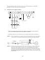
8
ON
SWF
Frequency
(Hz)
(Source type)
Fourth (FS)
speed
Third
speed
Second
speed
First
speed
Switch
SW1
SW2
SWF
1
•••••
SWR
ON
SW2
SW3
CM1 PLC P24 FW
CM1PLC P24 FW 8
Time
ON
ON
ON
ON
ON
ON
ON
SWF
7
6
SW1 SW2
• When setting frequency,
connect P24 and 6 or 7
and set with digital
operator 1 or 2 .
Jogging run
DC braking input signal
Initialization (shipment status at factory) input
The output frequency setting, base and maximum frequencies,
control method, motor constant, acceleration or deceleration time,
manual torque boost setting, and electronic thermal setting are
changed in batch.
The acceleration or deceleration time or selection of two-stage
accration or deceleration is changed by turning the contact ON.
The inverter stops and the motor stops free run
FRS functions when the contact is opened. (European version)
External trip input signal (The contact is open.)
Restart prevention when the power is turned on in the RUN
state (The contact is open.)
Switch signal from the commercial power source to inverter
drive (Note: When the terminal is used, a trip is also conceled.)
The data of all funcitons except for output frequency setting is
locked. See 12-9 [F-25].
Analog input voltage-current switching (When the contact is ON,
current input signal to OI-L is acrive.)
Trip or alarm signal is reset.
When the contact is turned ON, the operation is accelerated.
(Available only when the frequency command is sent
to the operator.)
When the contact is turned ON, the operation is decelerated.
(Available the frequency command is sent to the operator.)
5-12
Terminal symbol
Terminal name
H
Frequency command power
terminal
O
Frequency command
terminal (voltage command)
Frequency command
terminal (current command)
Frequency command
common terminal
OI
L
Description
• Initialization of a voltage signal by an external command
is between 0 and 10 VDC. (Switching from 0 to 5V is executed
by A48.) When inputting 4 - 20 mA, turn the input terminal at
ON.
H O OI L
H O OI L
+
VRO
(500 Ω to 2 kΩ)
H O OI L
-
+
-
DC0 to 10 V
DC4 to 20 mV
DC0 to 5V
Input impedance 250 kΩ
Input impedance 30 kΩ
When a current is inputted from between OI and L and the value is 4 mA,
the output frequency may 0.6 Hz. If this occurs, set a value more than the
frequency which is outputted by [A 4] start frequency setting.
(NOTE 2)
11 • 12
CM2
FA1
Common terminal 2
Frequency arrival signal
RUN
Signal during run
OTQ
Over-torque signal
Common terminal for intelligent output terminal
When each operator is used, and arrival signal can be
outputted at an optional frequency.
The transistor output is turned ON during running.
(Outputted even during DC injection braking)
The transistor output is turned ON when the torque is more
than the set value.
The set value can be changed by the remote operator.
Use this function only under the sensor less vector control.
AL0
AL2 AL1 AL0
AL1
AL2
Normal: AL0-AL1 close
Abnormal, Power off:
AL0-AL1 open
Fault alarm terminal
Contact rating
250 VAC 2.5 A (Resistor load)
0.2 A (Cosø=0.4)
30 VDC 3.0 A (Resistor load)
0.7 A (cosø=0.4)
Min 100Vac
10 mA
5 VDC
100 mA
NOTE 1: To set four or more multispeeds, use the CF3 terminal.
NOTE 2: When an inconvernience occurs in the above characteristics, adjust it using
and
. The sum of both analog input signals is outputted
When selecting one of analog input current and voltage, make sure that the other
is not inputted.
5-13
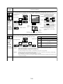
5.7
Terminal Connection Diagram
Mg
Power supply
AX
BSS
EF
AX
BSS
Mg
Inverter
ELB
Mg
Three phase
power supply
R (L1)
(T1) U
S (L2)
(T2) V
(T3) W
T (L3)
Motor
24 VDC
P24
PLC
FW
(+) P
➤
P
AL1
RB
AL1
8
RB
7
➤
..
..
.
P24
AL0
AL1
1
FM
AL2
➤
CM1
10 VDC
➤
Current input
➤
4 to 2\0 mA
➤
2
➤
Frequency setter
500Ω to 2 kΩ
Fault alarm signal
(Normal: AL0-AL1 ON)
11
RY
12
RY
➤
H
3
Dynamic braking resistor
055, 075LF: RB1,RB2 or RB3
055, 075HF: RB2, two each in series.
O
➤
24 VDC
OI
1
L
CM2
➤
Follow the timing shown as below
upon power on.
G
(PE)
Grounding
(NOTE 4)
➤
➤
Main circuit
power supply
0.6 or more seconds
Operation
command
NOTE 1: Common terminal for each terminal is different.
Output
frequency
Terminal
FM
FW, 8 to 1
H, O, OI
11, 12
Number
of
name
revolutions
*
Command CM1
CM1 (P24)
L
CM2
of motor
*: P24 is for source type wiring.
NOTE 3: When the operation command is input first
and the main circuit power is turned ON,
and direct start results and a trip occurs.
NOTE 2: The regenerative resistor has a temperature sensor.
NOTE 4: Do not input the operation command
When it works, turn off power supply to the inverter
simultaneously when the main circuit
o set the deceleration time longer.
is turned on.
5-14
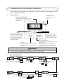
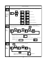
6. OPERATION
6.1
Before Starting Operation
Prior to the test run, check the following.
WARNING
*
*
*
*
*
*
*
*
Be sure to turn on the input power supply after mounting the surface cover. While
being energized, be sure not to remove the cover.
Otherwise, there is a danger of electric shock.
Be sure not to operate the switches with wet hands.
Otherwise, there is a danger of electric shock.
While the inverter is energized, be sure not to touch the inverter terminals even during
stoppage.
Otherwise, there is a danger of electric shock.
If the re-try mode is selected, it may suddenly restart during the trip stop. Be sure not
to approach the machine. (Be sure to design the machine so that personnel safety will
be secured even if it restarts.)
Otherwise, there is a danger of injury.
Even if the power supply is cut for a short period of time, it may restart operation after
the power supply is recovered if the operation command is given. If it may incur
danger to personnel, be sure to make a circuit so that it will not restart after power
recovery.
Otherwise, there is a danger of injury.
The Stop Key is effective only when the function is set. Be sure to prepare the Key
separately from the emergency stop.
Otherwise, there is a danger of injury.
After the operation command is given, if the alarm reset is conducted, it will restart
suddenly. Be sure to set the alarm reset after checking the operation command is off.
Otherwise, there is a danger of injury.
Be sure not to touch the inside of the energized inverter or to put a bar into it.
Otherwise, there is a danger of electric shock and/or fire.
6-1
CAUTION
Radiating fin and discharging resistor will have high temperature. Be sure not to touch
them.
Otherwise, there is a danger of getting burned.
Low to high speed operation of the inverter can be easily set. Be sure to operate it
after checking the tolerance of the motor and machine.
Otherwise, there is a danger of injury.
If a motor is operated at a frequency higher than 60Hz, be sure to check the speeds of
the motor and the machine with each manufacturer, and after getting their consent,
operate them.
Otherwise, there is a danger of machine breakage.
*
*
*
Note:
(1) Make sure that the power lines (input power supply R(L1), S(L2) and T(L3), and output
terminals, U(T1), V(T2) and W(T3) are connected correctly.
(2) Make sure that there are no mistakes in the signal line connections.
(3) Make sure that the inverter case (
) is grounded.
(4) Make sure that terminals other than those specified are not grounded.
(5) Make sure that the inverter is installed vertically on a wall, and a nonflammable material
such as a steel plate is used as a mounting surface.
(6) Make sure that there are no short-circuits caused by stray pieces of wire, solderless terminals or other objects left from wiring work. Also, make sure that no tools have been left
behind.
(7) Make sure that the output wires are not short-circuited or grounded.
(8) Make sure that there are no loose screws or terminals.
(9) Make sure that the maximum frequency setting matches the machine specifications.
Be sure to refer to page 10-2 when conducting insulation resistance and withstand
voltage tests. Never test terminals other than those which are indicated.
6-2
6.2
Test Run
CAUTION
Check the following before and during the test run.
Otherwise, there is a danger of machine breakage.
•
•
•
•
Was the direction of the motor correct?
Was the inverter tripped during acceleration or deceleration?
Were the SPEED (rpm) and frequency meter correct?
Were there any abnormal motor vibrations or noise?
When overcurrent tripping or overvoltage tripping occurs during the test run, increase
the acceleration time or deceleration time.
Factory settings
Maximum frequency: 60 Hz
Forward operation
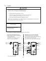
An example of a general connection diagram is shown below.
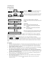
Operating with digital operator:
When setting frequency, run and stop
with digital operator.
(The same way as remote operator
(DOP) or copy with (DRW).)
Running from external command:
When setting frequency, run and stop
from external command (FW,RV Terminal.)
The following shows run from
the operation box (OPE-4MJ2,OPE-8MJ2)
Inverter
ELB
Three L1
phase L2
power L3
supply
R(L1)
S(L2)
T(L3)
*
FW
CM1 Digital
PLC operator
AL0
P24
AL1
8
AL2
1
H
11
O
OI
12
L
G
(PE)
Inverter
ELB
(T1)U
(T2)V
(T3)W
RB
(+)P
(-)N
Three L1
phase L2
power L3
supply
R(L1)
S(L2)
T(L3)
Dynamic braking
resistor
Daynamic
braking unit
Frequency meter
Fault alarm signal
(Normal:
AL0-AL1: ON
Abnormal:
Power off:
AL0-AL1: OFF)
Forward
run/stop
Reverse
run/stop
Frequency
setter
*
H
O
L
Operator
OPE-4MJ2
OPE-8MJ2
CM2
(T1)U
(T2)V
(T3)W
RB
(+)P
(-)N
PLC
P24
FW Digital
8
operator
FM
AL0
CM1
AL1
AL2
H
O
11
OI
L
12
G
(PE)
CM2
Ground
Ground
*: For sink type wiring.
6-3
Motor
Dynamic braking
resistor
Daynamic
braking unit
Fault alarm
signal
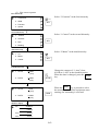
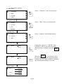
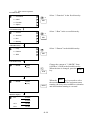
Operating with digital operator:
Runnign from external command:
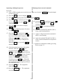
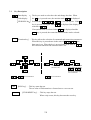
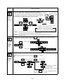
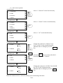
Procedure
(1) Turn on ELB to supply power to the inverter. Make sure that the POWER LED on the digital
operator turns ON.
(2) Press the
(3) Press
2
FUNC
key once to display
.
of the digital operator four times to display
(4) Press the
FUNC
key and then press the
2
(4) Press the
key to set
. Press the FUNC key to
establish the data.
(5) Press the 1 key four times to display
.
FUNC
key and then the
1
key
FUNC
key is pressed,
key and then press the
2
(7) Apply a voltage between the terminals O
and L to start running.
so as to increase to frequency or the 2
key so as to decrease the frequency.
(When the 1 or 2 key is pressed continuously, the frequency is changed continuously.)
When the
displayed.
FUNC
key to set
. Press the FUNC key to
establish the data.
(5) Press the 1 key four times to display
.
(6) Short the terminals FW and P24 (CM1*)
of the control terminal block.
(6) Press 1 of the digital operatort five times
to dispaly
.
(7) Press the
.
(8) Open the terminals FW and P24 (CM1*)
of the control terminal block to stop deceleration.
is
*: Symbols are indicated for Sink type wiring.
Refer to page 5-5.
(8) Check the output frequerncy and rotation
direction. When the 1 or 2 key is
pressed to display
and then the
key is pressed, the rotation direction
can be checked.
indicates forward
FUNC
rotation and r
indicates reverse
rotation. When the rotation direction is
checked, press the FUNC key. When the
rotation direction cannot be found, operate
the equipment at a low frequency to check
the rotation direction.
(9) Presst the RUN key. The equipment
starts running.
(10) Press the STOP/RESET key. The equipment
decelerates and stops.
6-4
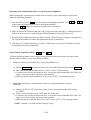
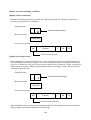
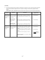
• The failure alarm signal is generated from the terminal AL0 and AL1 when a failure happens. At this time the contents of the failure are displayed on the digital operator.
• Whether the alarm terminal output is to be turned on or off during normal run can be
.
selected by the extension function
The alarm output terminals at initial setting are as follows (1).
The alarm output terminals are valiable as follows (2) by setting
(2) Contact a
(1) Contact b
AL2
AL1
During normal operation
or at power off
At occurrence of an
alarm or power off
During normal operation
AL0
AL2
Contact Power Operation
Status
ON
Normal
b
(initial
ON Abnormal
setting) OFF
Ñ
.
AL1
AL0
AL0-AL1
AL0-AL2
Closed
Open
Open
Open
Closed
Closed
AL2
AL1
At occurrence of an alarm
AL2
AL0
Contact Power Operation
Status
ON
Normal
a
ON Abnormal
OFF
Ñ
AL1
AL0
AL0-AL1
AL0-AL2
Open
Closed
Open
Closed
Open
Closed
• Contact specification
Maximum
Minimum
250 VAC 2.5 A (Resistor load) 0.2 A (cos¿=0.4)
100 VAC 10 mA
30 VDC 3.0 A (Resistor load) 0.7 A (cos¿=0.4)
5 VDC 100 mA
Working voltage: Max. 50 V
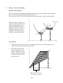
• Saving the alarm signal
When an alarm signal is outputted, the alarm signal data is stored even if the input power is
turned off and the contents can be checked by turning the power on once again. However,
when the input power is turned off, the inverter control power is also turned off. As a
result, when the power is turned on next, the alarm contact output is reset (deleted). Therefore, when saving the alarm contact output, let the external sequence receive and save it
and then turn off the inverter input power.
• When the alarm contact output is set ON during normal run, a time delay occurs until the
contact is closed when the power is turned on. Therefore, when using the alarm contact
output, set a time delay of about 2 seconds when the power is turned on.
6-5
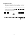
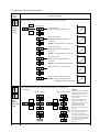
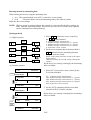
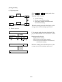
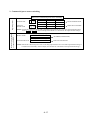
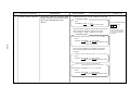
Resetting (Any one of A, B and C is possible)
CM1 PLC
P24
A) Turn control terminal 1 on. (In the
initialization at factory before shipment, intelligent input terminal 1 is
allocated to the reset RS terminal.)
1
B) Press
When the internal interface power source
P24-CM1 is used (Source type wiring)
CM1 PLC
P24
STOP/RESET
on the digital
operator. (This is effective only when
an alarm occurs.)
1
C) Open the power receiving breaker of
the inverter, and make sure that the
Charge lamp on the control board
goes out. (See page 3-1.) Then, close
the power receiving breaker.
When the internal interface power source
P24-CM1 is used (Sink type wiring)
NOTE: When the control circuit terminal RS is used, never short-circuit RS-P24 (CM1*)
for four seconds or more. Otherwise, a communication error
R-ERROR COMM<2> may occur (Although the digital operator display is
, the inverter is normal). When the above error occurs, open the RS terminal and press the operator key.
*: For sink type wiring
How to return to the initialization (state before shipment)
When returning the equipment to the initial state set at factory before shipment for some
reason, see page 7-14.
6-6
7. OPERATION OF THE DIGITAL OPERATOR
The standard type digital operator is modified so as to be used easily by minimizing key operations. Data can be set simply.
7.1
Names of Parts
POWER Lamp
Monitor (LED display)
Power lamp of control
circuit
This display shows frequency, motor
current, motor revolution speed, and
Trip history
FUNC.
FUNC (Function) key
Up key, Down key
This key is used for changing
commands. When pressing
key after setting data and
parameter, they are automatically memorized.
RUN
STOP/RESET
These keys are used to
change data and increase
or decrease the frequency.
STOP/RESET key
This key is used for stopping the motor or
resetting errors.
(When either operator or terminal is selected, this key works. If the extension
function is used, this function is void.)
RUN key
This key is used for starting. (When
terminal run is selected, this key does
not work.)
WARNING
The STOP/RESET key works only when a function is set. Prepare an emergency switch separately.
The use of the STOP/RESET key as an emergency switch may cause an injury.
l
Operation Procedure
(Example that the frequency is set and the equipment starts running)
➤
➤
(Frequency
monitor)
Press the FUNC
key once.
➤
Start
run
When selecting the monitor Press RUN
mode, press 1 and 2
to display
.
7-1
.
Press the FUNC key once
and set the frequency by using
the 1 and 2 keys.
Press the 1
key five times.
➤
.
Press the FUNC
key once.
➤
➤
Display after
power is turned
on
➤
➤
7.2
The frequency which is
set by the FUNC key is
stored.
7.3
Key Description
2
1
Data display
The key are used to select the code and change the data. When
Code display
the
UP/DOWN key
first and then
1
key is pressed once, the monitor mode
,
,
, •••• are one by one. If the
key is pressed once again when
returned to
.
FUNC
1
is displayed, the display is
If an optional code is selected when
FUNC
is displayed
is displayed and the
key is pressed, the extension function mode can be selected.
[Function key] . . . This key allows the selection of commands and memorizes parameters.
When this key is pressed once in the state of
,
, the
data state is set. When the key is pressed once in the state of
,
the extension function code selection state is set.
.
➤
2
1
.
➤
FUNC
FUNC
➤
FUNC
➤
➤
➤
2
2
➤
Select the extension
function code.
1
➤
.
.
➤
A setting method which
is the smame as that for
to
is
used for the subsequent
screen transition.
screen transition
RUN
FUNC
1
screen transition
[RUN key] . . . This key starts the run.
The set value of F4 determines a forward run or a reverse run.
STOP/RESET
[STOP/RESET key] . . . This key stops the run.
When a trip occurs, this key becomes the reset key.
7-2
Explanation of Screen Display
• When the inverter is turned on, the latest display appears. However, when the display
unit for data of the commands F2 to F14 is turned off, the commands (F2 to F14) are
displayed. (d10 and d11 excluded)
• Data during running in any function mode or extension function mode can be displayed.
Even if data cannot be changed during running, data can be monitored.
• In each of the function modes
,
,
,
, and
, data
can be changed even during running. In other function modes and extension function
modes, data cannot be set during running.
➤
to
RUN
Or data display
to
The display is left unchanged.
Running start
➤
7.4
,
Code which can change data during running
7-3
.
FUNC
Data can be changed
even during running
7.5
Transition of Each Code
➤
<Monitor mode>
➤
➤
Output frequency
monitor
Motor revolution
speed monitor
➤
➤
Frequency converted
value monitor
Speed control response
constant setting
Start frequency adjustment
➤
➤
➤
➤
Trip history
monitor
➤
➤
➤
➤
Output frequency
setting
➤
➤
Running direction
setting
➤
➤
Acceleration time
setting
➤
➤
➤
➤
Motor capacity setting
Motor poles setting
<Function mode>
Deceleration time
setting
Manual torque boost
setting
Run command,
frequency command
➤
➤
➤
➤
Control method setting
Output current
monitor
Trip monitor
Analog meter
adjustment
➤
➤
To extension function code setting
➤ <Extension function mode>
Motor receiving
voltage
➤
Extension function
setting
➤
When the FUNC key is pressed once
to set the extension function, the
screen is changed to the extension
function code selection screen.
When a code is selected from the
codes
to
and the
FUNC key is pressed, the screen is
changed to the relevant extension
function settig screen.
Maximum frequency
limiter setting
Minimum frequency
limiter setting
Jump frequency setting 1
Jump frequency setting 2
Jump frequency setting 3
Carrier frequency setting
Frequency command sampling
frequency setting
Multispeed first
speed setting
Multispeed second
speed setting
Multispeed third
speed setting
Electronic thermal level
adjustment
Electronic thermal
characteristic selection
Motor pole number setting
for motor speed monitor
External frequency setting
start
External frequency setting
end
Instantaneous restart
selection
Dynamic braking usage
ratio
Optional arrival frequency
for acceleration
Optional arrival frequency
for deceleration
Monitor signal selection
Reduced voltage soft
start setting
Running mode
selection
Jogging frequency
setting
Base frequency
setting
Maximum frequency
setting
Maximum frequency
selection
Frequency command/
output frequency adjust
(O−L terminal)
Frequency command/
output frequency adjust
(OI−L terminal)
Selection of reset
terminal performance
P gain setting of PID
funciton
I gain setting of PID
function
D gain setting of PID
funciton
Selection of PID
funciton
Setting method of PID
reference value
Setting of PID
reference value
Auto tuning setting
Motor data selection
Ro-To option selection
Input terminal setting 1
Input terminal setting 2
Input terminal setting 3
Input termianl setting 4
Input terminal setting 5
Input terminal setting 6
Input terminal setting 7
Frequency converted
value setting
Analog input selection
Input terminal setting 8
Frequency arrival signal
output method
Restarting after FRS
signal selection
Output terminal setting 12
7-4
Output terminal setting 11
Input terminal a and b
contact setting
Output terminal a and b
contact setting
7.6
Digital Operator Initialization List
(1) Monitor mode, function mode
• The standard set value of each code number is displayed.
• The extension functions shown on page 7-6 can be set by the
function setting function.
extension
Screen display
Display
order
Function name
1
Output frequency monitor
2
Type
Initial
value
Settable
Set
for 2nd
function value
Code
display
Settable
during
running
Monitor/set value
Monitor
d0
—
0.00-9.99/10.0-99.9/100-400
—
—
Motor revolution speed
monitor
Monitor
d1
—
0.00-9.99/10.0-99.9/100-600
—
—
3
Output current monitor
Monitor
d2
—
0.0-999
—
—
4
Frequency converted value
monitor
Monitor
d3
—
0.00-9.99/10.0-99.9/100.-999.
100-999/ 10- 99
—
—
5
Trip Monitor
Monitor
d10
—
—
—
—
6
Trip history monitor
Monitor
d11
—
—
—
—
7
Output frequency setting
Set value
F2
√
0.00-9.99/10.0-99.9/100-400
0.00
√
8
Running direction setting
Set value
F4
Not possible
F/r (forward run/reverse run)
F
—
9
Acceleration time setting 1
Set value
F6
√
0.01-9.99/10.0-99.9/100-999
30.0
√
10
Deceleration time setting 1
Set value
F7
√
0.01-9.99/10.0-99.9/100-999
30.0
√
11
Manual torque boost setting Set value
F8
√
00-99
11
√
12
Runn command, frequency
command setting
Set value
F9
Not possible
00-15
03
—
13
Analog meter adjustment
Set value
F10
√
00-250
172
—
14
Motor receiving voltage
Set value
F11
Not possible
200-230/380-480
230/460
—
15
Extension function setting
Set value
F14
Not possible
A 0-A99/C 0-C21
A0
—
NOTE 3
NOTE 1
NOTE 2
NOTE 1: In the standard configuration, four values from 0 to 3 can be selected. When an
optional PC board is mounted, 16 values from 0 to 15 can be selected. Refer to
F-9.
NOTE 2: For the 200 V class, one of 200, 215, 220, and 230 can be selected.
For the 400 V class, one of 380, 400, 415, 440, 460 and 480 can be selected.
NOTE 3: Set torque boost in 70 to 90 when using VP1, VP2 or VP3 in V/F control mode.
7-5
(2) Extension function mode
• Each function name and settable range to the extension function mode are shown
below.
• Set the extension function code to be changed by
.
Display
order
1
2
3
4
5
6
7
8
9
Screen display
Externsion function name
Control method setting
Motor capacity setting
Motor poles setting
Speed control response constant setting
Start frequency adjustment
Maximum frequency limiter setting
Minimum frequency limiter setting
Jump frequency setting 1
Jump frequency setting 2
10
11
Jump frequency setting 3
Carrier frequency setting
12
13
14
15
16
17
18
19
20
21
22
23
Frequency command sampling frequency
Multispeed first speed setting
Multispeed second speed setting
Multispeed third speed setting
Electronic thermal level adjustment
Electronic thermal characteristic selection
Motor pole number setting for motor speed monitor
External frequency setting start
External frequency setting end
Instantaneous restart selection
Dynamic braking usage ratio
Optional arrival frequency for acceleration
24
25
26
27
28
Optional arrival frequency for deceleration
Monitor signal selection
Frequency converted value setting
Analog input selection
Frequency arrival signal output method
29
30
31
32
Restarting after FRS signal selection
Reduced voltage soft start setting
Running mode selection
Jogging freguency setting
33
34
Base frequency setting
Maximum frequency setting
35
36
Maximum frequency selection
Frequency command/output frequency adjust (O-L terminal)
Frequency command/output frequency adjust (OI-L terminal)
Selection of reset terminal performance
P gain setting of PID funciton
I gain setting of PID funciton
D gain settingof PID function
Selection of PID funciton
37
38
39
40
41
42
43
44
45
46
47
48
49
50
51
52
53
54
55
56
57
58
59
Setting method of PID reference value
Setting of PID reference value
Auto tuning setitng
Motor data selection
Ro-To option selection
Input terminal setting 1
Input terminal setting 2
Input terminal setting 3
Input terminal setting 4
Input terminal setting 5
Input terminal setting 6
Input terminal setting 7
Input terminal setting 8
Output terminal setting 11
Output terminal setting 12
Input terminal a and b contact setting
Output terminal a and b contact setting
Settable
for
2nd
function
Code
display
Settable
during
running
Setting range
Initial value
A0
A1
A2
A3
A4
A5
A6
A7
Ñ
Ñ
Ñ
Ñ
Ñ
Ñ
Ñ
Ñ
0-5
3.7 to 160
2/4/6/8
0.00-9.99/10.0-99.9/100
0.10-9.99
0-120 (400)
0-120 (400)
0-400
0
4
2.00
0.50
0
0
0
√
√
√
√
Ñ
Ñ
Ñ
Ñ
A8
A9
A10
A11
A12
A13
A14
A23
A24
A25
A26
A27
Ñ
Ñ
Ñ
Ñ
Ñ
Ñ
Ñ
Ñ
Ñ
Ñ
Ñ
Ñ
0-400
0-400
2.0-16.0
1-8
0-120 (400)
0-120 (400)
0-120 (400)
20-120
0-2
2 to 48
0-120 (400)
0-120 (400)
0
0
(16.0)
8
0
0
0
100
1
4
0
0
Ñ
Ñ
Ñ
Ñ
Ñ
Ñ
Ñ
√
√
Ñ
Ñ
Ñ
A34
A38
A39
A40
Ñ
Ñ
Ñ
Ñ
0-3
0.0-99.9/100
0-400
0-400
0
(1.5)
0
0
Ñ
Ñ
Ñ
Ñ
A44
A47
A48
A49
A54
A58
A59
A61
Ñ
Ñ
Ñ
Ñ
Ñ
Ñ
Ñ
Ñ
0-3
0.0-99.9
0-1
0-2
0-1
0-6
0-2
0-9.99
0
1.0
1
0
1
6
0
1.00
Ñ
Ñ
Ñ
Ñ
Ñ
Ñ
Ñ
Ñ
A62
A63
A64
Ñ
Ñ
Ñ
30-120 (400)
30-120 (400)
120/400
60
60
120
√
√
Ñ
A80
A81
Ñ
Ñ
0-255
0-255
Ñ
Ñ
Ñ
Ñ
A86
A90
Ñ
Ñ
0, 1
0.1-0.5
0
1.0
Ñ
Ñ
A91
A92
A94
A95
A96
A97
A98
Ñ
Ñ
Ñ
Ñ
Ñ
Ñ
Ñ
0.0-15.0
0.0-100
0-4
0, 1
0.00-200
0-2
0-2
1.0
0.0
0
0
0.00
0
0
Ñ
Ñ
Ñ
Ñ
Ñ
Ñ
√
A99
C0
Ñ
Ñ
0-1
0-3, 5-9, 11-16, 18-28
0
18
Ñ
Ñ
C1
C2
Ñ
Ñ
0-3, 5-9, 11-16, 18-28
0-3, 5-9, 11-16, 18-28
16
5
Ñ
Ñ
C3
C4
C5
C6
C7
C10
C11
C20
C21
Ñ
Ñ
Ñ
Ñ
Ñ
Ñ
Ñ
Ñ
Ñ
0-3, 5-9, 11-16, 18-28
0-3, 5-9, 11-16, 18-28
0-3, 5-9, 11-16, 18-28
0-3, 5-9, 11-16, 18-28
0-3, 5-9, 11-16, 18-28
0-2
0-2
00-FF
00-07
11
9
13
1
0
0
1
00
04
Ñ
Ñ
Ñ
Ñ
Ñ
Ñ
Ñ
Ñ
Ñ
Remarks
NOTE 1
See 7-18
See 7-21
Frequencies below
the start frequency
cannot be set.
NOTE 2
NOTE 2
NOTE 1: The most applicable motor capacity of the inverter is set.
NOTE 2: The initial setting of each inverter is adjusted when shipping from the works.
7-6
Set
value
7.7
Explanation of Modes
(1) Monitor mode contents
Monitor
mode
contents
Contents and display
The frequency outputted by the inverter is monitored.
The display is as shown below.
Display when stopped
.
Output
frequency
monitor
(1)
to
.
A frequency between 0.01 Hz
and 9.99 Hz is displayed in units
of 0.01 Hz.
.
FUNC
➤
(2)
.
to
A frequency between 10.0 Hz
99.9 Hz is displayed in units
of 0.1 Hz.
.
➤
FUNC
(3)
A frequency between 100 Hz and
400 Hz is displayed in units of
1 Hz.
to
The rotational frequency converted value of the frequency outputted by the inverter
is displayed.
(Note that the value is not the real rotational frequency of the motor.)
The converted value is displayed as shown below using "rotational frequency/100."
Display when stopped
.
Motor
rotation
speed
monitor
(1)
to
.
The converted value is displayed
in units of 0.01 (1 rpm).
From 1 to 999 rpm
.
FUNC
➤
(2)
.
to
The converted value is displayed
in units of 0.1 (10 rpm).
From 1000 to 9990 rpm
.
➤
FUNC
(3)
The converted value is displayed
in units of 1 (100 rpm).
From 10000 to 60000 rpm
to
NOTE: Motor pole number can be set by
.
The current outputted by the inverter is monitored. The display is as shown below.
Display
when
stopped
.
Output
current
monitor
FUNC
The output display accuracy is about ±10%.
Inverter output current:
IM
Monitor display current:
IMC
Rated current of the inverter: IR
IMC - IM
× 100 ≤ ±10%
IR
.
to
.
A current between 0.1 and 99.9 A
is displayed in units of 0.1 A.
➤
➤
FUNC
(2)
to
7-7
A current between 100 A and 999 A
is displayed in units of 1 A.
Monitor
mode
contents
Contents and display
The product of the value of frequency converted value setting (A47) and that of output frequency
(d0) is displayed on the monitor.
FUNC
(1)
to
.
➤
0.0 to 9.99
.
➤
Frequency
converted
value
monitor
(2)
to
.
FUNC
(3)
.
10.00 to 99.99
.
to
.
100.00 to 999.99
(4)
to
1000.00 to 9999.99
(5)
to
10000.00 to 39960.00
When a trip occurs, the cause of the trip is displayed in this code. As a general display,
the contents of the latest trip are displayed. Whenever the FUNC key is pressed, the content
of each is displayed.
FUNC
Trip
monitor
FUNC
➤
➤
➤
➤
FUNC
Trip cause
Trip current
NOTE 1: When there is no trip,
Voltage between trips
P and N
(Note 2)
is displayed.
NOTE 2: The above example of the voltage between P(+) and N(-) indicates 390 to 399 V.
NOTE 3: When the
STOP/RESET
key is pressed after a trip occurs,
.
is displayed.
The causes of the last trip and the last trip but one are displayed. When the command is displayed
and the FUNC key is pressed, the trip cause is displayed.
FUNC
FUNC
➤
➤
➤
Trip
history
monitor
Cause of the last trip
Cause of the last trip
but one
FUNC
NOTE 1: When there is not a trip history,
is displayed.
NOTE 2: How to delete trip history data, see page 7-14.
7-8
(2) Function mode
Monitor
mode
contents
Contents and display
Methods for setting the output frequency are as follows:
1. Digital operator
Refer to this setting.
2. Control circuit terminal
Refer to this setting.
(multistage speed command)
3. External analog input
Refer to page 6-2.
Output
(0 to 10 V, 0 to 5 V, 4 to 20 mA)
frequency
4. Remote operator
Refer to the explanation of each remote operator.
setting
(new type, general purpose)
5. Optional PCB
Refer to each optional PCB operation.
(1) Setting from the digital operator
.
A frequency between 0.01 Hz and 9.99 Hz is
set in units of 0.01 Hz.
.
➤
2
➤
➤
FUNC
When the
.
1
➤
FUNC
A frequency between 10.0 Hz and 99.9 Hz is
set in units of 0.1 Hz.
.
A frequency between 100 Hz and 400 Hz is
set in units of 1 Hz.
Initial set value
1
or
2
key is pressed continuously, the value is changed continuously.
(2) Setting from the control circuit terminal (multispeed setting)
The output frequency at the multispeed can be set as specified below. When the running
mode is the process stepping mode, switch it to the multistage speed mode by the remote operator.
① Connect the multispeed terminal for setting the frequency to CM1.
(The relationship between multispeeds 1 to 7 and the control circuit terminals is as
shown below.)
Multispeed
7
6
CM1
5
CF1 CF2 CF3
Example of terminal connection
for sink type
Refer to page 5-5.
Multispeed 1
Multispeed 2
Multispeed 3
Multispeed 4
Multispeed 5
Multispeed 6
Multispeed 7
Control circuit terminal
1
2
3 (*1)
ON
OFF
OFF
ON
OFF
ON
ON
ON
OFF
OFF
ON
ON
ON
ON
OFF
OFF
② Set an optional output frequency using the
③ Press the
FUNC
NOTE 2:
④ Press the
1
or
2
*1: By initialization, the multispeed can be
set up to the third stage. When CF3 is set by
terminal allocation (in this case, intelligent
input terminal 5 is allocated), up to the 7th stage
can be set (set by the extension function mode
C4).
Intelligent input terminal allocation: C0 to C7
Set value: 3 (CF3)
key.
key once to store the set output frequency.
is displayed.
1
key once. (Check whether the output frequency, which is set,
is displayed.)
⑤ By repeating (1) to (4), the output frequency in the multispeed mode can be set.
NOTE 3:
NOTE 4:
Whenever any data is changed, be sure to press the
FUNC
key before starting
the next setting. Note that when the FUNC key is not pressed, the data will
not be set.
When setting to over 120 Hz, the changing over maximum frequency is necessary.
Remote operator or copy unit must be used.
(When the value is switched to 400 by F-30, an output frequency of up to 400 Hz
can be set.)
7-9
Monitor
mode
contents
Contents and display
Set the motor direction.
Set the motor direction when running by pressing the RUN key.
NOTE: The setting during run is impossible.
FUNC
Initial set value
➤
➤
Running
direction
Forward run
FUNC
Reverse run
7-10
Switching can be done by pressing
the 1 2 key.
Monitor
mode
contents
Contents and display
These commands set and display Acc. time (
) and Dec. time (
).
➤
Acceleration time 1
and 2
Deceleration time 1
and 2
1
➤
1
FUNC
Initial value
➤
Setting range
FUNC
0.01 to 9.99s
10.0 to 99.9s
100 to 999s
➤
.
➤
Period
Every 0.01s
Every 0.1s
Every 1s
2
➤
2
.
• Acceleration time 2 and deceleration time 2 are set when CH1 is connected with P24.
• When a time of more than 1,000 seconds is set by the remote operator,
is displayed on the digital operator.
Set torque boost
• Motor torque can be adjusted to increase the output voltage when the starting torque
is not sufficient in V/F control. Pay attention not to cause the motor to burnout and
an inverter trip. Set boost value in 70 to 90 when using VP1, VP2 or VP3 in V/F control mode.
• Setting is effective only when V/F control is selected.
Setting method
Output
voltage
100%
➤
2
➤
1
FUNC
Initial value
➤
FUNC
A
➤
About 11.8
1
➤
➤
2
➤
Manual
torque
boost
setting
0
With the remote operator (DOP, DRW, HOP, or HRW),
point A in the torque boost graph can be changed within
the range of 0% to 50% with respect to the base frequency.
7-11
5 10
6 12
25
30
Output
frequency
50 Hz
60
(V-Boost F 20.0% is set
with the remote operator.)
Monitor
mode
contents
Contents and display
Switching the run command and frequency command setting modes
Set the run command and frequency command sending destinations. The standard specification
selection range is from 00 to 03.
Set value
Run
commanding
method
Initial value
➤
Frequency command to
Digital operator
Digital operator
Digital operator
Terminal block
Terminal block
Digital operator
Terminal block
Terminal block
Digital operator
Option 1
Option 1
Digital operator
Option 1
Option 1
Digital operator
Option 2
Option 2
Digital operator
Option 2
Option 2
Terminal block
Option 1
Option 1
Terminal block
Terminal block
Option 2
Option 2
Terminal block
Option 1
Option 2
Option 2
Option 1
Setting method
➤
2
1
➤
Frequency
commanding
method
Run command to
FUNC
Initial value
➤
FUNC
➤
NOTE1: The run command and frequency command sending destinations can be set to any
of the terminal, operator, option 1, and option 2. Select the relevant set value.
NOTE2: When option 1 or option 2 is selected for "Run command to" and "Frequency command
to," the digital operator and terminal block cannot issue commands. Set option 1
or option 2 (set values
) only for operation or frequency commands
from the optional PC board.
7-12
Monitor
mode
contents
Adjust the analog meter connected to the frequency monitor
terminal. (Initial setting of the [FM] terminal: Analog frequency monitor)
When operation starts, t/T output between FM and CM1 terminals is
proportional to the output data. Adjust the meter so that it indicates
the maximum point when the output is at the maximum.
t
Sink type wiring
Refer to page 5-3
FM
CM1
PLC
P24
➤
➤
➤
2
1
➤
FUNC
T
➤
Analog
meter
adjustment
Contents and display
Initial value
FUNC
t (variation)
T
➤
When adjusting the analog meter furthermore, repeat the same operation.
➤
➤
➤
Output =
2
1
➤
Maximum level of analog meter
Frequency monitor: (A63 maximum frequency setting)
Current monitor:
(200% of inverter rated current)
Torque monitor:
(200% of rated torque)
NOTE 1: This function is valid only when the analog monitor is used.
(Freqency monitor, current monitor, torque monitor)
NOTE 2: The adjusted value when the input terminal STN (initialization) is used is
the initial value.
Set the motor receiving voltage. When the FUNC key is pressed once, the current set value
of the motor receiving voltage is displayed.
1
➤
FUNC
➤
➤
➤
Motor
receiving
voltage
setting
200 V class
Initial value
2
1
FUNC
➤
400 V class
➤
Initial value
2
Select the item of each extension function. After setting, the display is returned to the code
display.
After data is changed, be sure to press the FUNC key to store it.
Code selection
➤
FUNC
Code selection
➤
➤
➤
FUNC
2
➤
FUNC
➤
Extension
function
setting
1
2
1
➤
➤
When the data is changed,
the display blinks.
(Set value storage wait state)
When the FUNC key is pressed, the display stops
blinking and the data is stored.
7-13
Returning to the initialization (State set at factory before shipment)
When returning the equipment to the initial state set at factory before shipment for some reason,
follow the following procedure.
1) Allocate STN (set value
) to one of the input intelligent terminals. (Use
in the extension function mode to set the intelligent terminals.)
(However,
to
cannot be used since resetting RS is initially set.)
2) Short-circuit the STN terminal and P24 (CM1*), then turn power off and on. (When the power is
turned off, do not turn it on again until the CHARGE lamp of the logic PCB goes off.)
3) Keep the STN terminal open for more than 6 seconds. (When keying, resetting, or turning power
off is performed within 6 seconds, the equipment may not be initialized.)
4) Turn the power off after more than 6 seconds. (When the power is turned off within 6 seconds,
the equipment may not be initialized.)
How to Delete Trip History Data (
, and
)
To delete trip history data for some reason, follow the instructions shown below using the remote
operator (DOP or HOP) or copy unit (DRW or HRW).
1.
Using the remote operator (DOP-OA) or copy unit (DRW-OA)
Display INIT TCNT (trip history count clear) or the function mode initial setting F-38 INIT .
(2) Move the cursor to beneath the initial set values. Select CLR and store it.
1) Turn the power off once and then turn it on. or close the reset terminal RS-P24 (CM1*) for
approx. a second. By this, trip history data is deleted.
2) When trip history is deleted, data of [F-38] is set to [CNT]. Trip counting restarts.
(1)
2.
Using high-performance remote operator (HOP-OJ) or high-performance copy unit
(HRW-OJ)
Display [TCNT 0: CNT] (trip history count clear) or the function mode initial setting
[2-1 INIT].
(2) Enter a count clearing value [0: CLR] from the 10-key pad.
1) Turn the power off once and then turn it on. or close the reset terminal RS-P24 (CM1*) for
approx. a second. By this, trip history data is deleted.
2) When trip history is deleted, data of [2-1 INIT] is set to [CNT]. Trip counting restarts.
(1)
NOTE: Symbols * are indicated for Sink type wiring.
7-14
(3) Extension function mode contents
Extension
function
code
Contents and display
Set the control method. Select one of the following control codes.
FUNC
V
V/f control (VC)
Constant torque characteristics
➤
➤
Control
method
setting
Initial value
➤
FUNC
2
1
➤
1
V/f control (VP2)
Reduced torque characteristics,
1.7 power
NOTE : set torque boost in 70 to 90
1
V/f control (VP3)
Reduced torque characteristics,
2.0 power
NOTE : set torque boost in 70 to 90
➤
1
V/f control (VP1)
Reduced torque characteristics,
1.5 power
NOTE : set torque boost in 70 to 90.
2
➤
➤
2
➤
➤
2
➤
0
V
f
0
V
f
0
V
f
0
V
f
0
V
f
0
f
➤
Sensorless vector control (SLV)
2
1
➤
Vector control with sensor (V2)
NOTE : Vector control INV only
(Feedback board is nesessary)
Set the motor capacity and number of motor poles according to the motor to be used.
The maximum rating of the applicable 4-pole motor for each inverter
NOTE :
is set initially.
When the data does not match
Motor capacity
No. of motor poles that of the mootor, satisfactory
.
1
➤
.
2
➤
➤
2
➤
➤
➤
FUNC
2
1
➤
➤
1
Initial
value
.
➤
➤
2
1
2
1
➤
➤
FUNC
1
➤
FUNC
➤
FUNC
➤
➤
2
Motor
capacity,
motor poles
setting
.
7-15
characteristics may not be
obtained during the sensorless
vector running.
The full performances may
not be demonstrated if the
rating of a motor used is tow or
less than the maximum
applicable rating when
the sensor-less vector function
is used.
The sensor-less vector operation is disabled when two or
more motors are running.
Set this data properly according
to the motor used if its rating is
not the same as the maximum
applicable rating in V/f
operation.
Extension
function
code
Contents and display
Set the response speed (ASR system gain) between the inverter and motor. When increasing
or decreasing the current motor response speed, adjust the ASR system gain. When the set value is
decreased, the response speed is increased. When the set value is increased, the response speed is
decreased.
1
.
➤
➤
A constant between 0.01
and 9.99 is set in units of 0.01.
.
2
FUNC
Initial value
➤
1
.
.
➤
➤
Speed
control
response
constant
setting
.
A constant between 10.0
and 99.9 is set in units of 0.1.
➤
2
FUNC
1
➤
A constant between 100
and 655 is set in units of 1.
➤
2
Set the frequency for starting output of the inverter.
Set a frequency between 0.1 Hz and 9.99 Hz in units of 0.01 Hz.
Output voltage
.
V
➤
2
.
➤
FUNC
➤
➤
2
,
,
nt
Initial value
A
ra dju
ng st
e me
➤
FUNC
1
➤
➤
1
➤
Start
frequency
adjustment
.
0
0.10 9.99
f
Maximum
frequency
When the start frequency is increased,
the acceleration or deceleration time is
decreased.
7-16
Extension
function
code
Contents and display
Set the limits of frequency setting within the
start frequency adjustment range and
maximum frequency setting range. When a value beyond the limits is inputted from the operator,
it will not be stored. Even if a value beyond the limits is inputted as external analog input, the set
value will not be changed.
Maximum
frequency limiter
,,
,,
Setting example
(When an upper limit of 45 Hz and a lower
limit of 20 Hz are set)
➤
2
1
➤
FUNC
➤
.
Initial value
Upper limiter 45
ge
➤
FUNC
Output frequency
(60 Hz)
➤
Se
tta
bl
er
an
Frequency
upper,
lower
limiter
(400)
➤
Minimum
frequency limiter
Lower limiter 20
(400)
➤
2
1
0
➤
FUNC
➤
.
Initial value
➤
FUNC
Frequency command
(F-SET)
NOTE: Setting conditions
0 Hz or upper limit ≥ lower limit
When 0 Hz is set, the limiters will not operate.
To avoid a resonance with the load, the frequencies at up to 3 points can be jumped. The setting
order and the execution order may be changed.
The frequency equivalent to the jump frequency setting width (± 0.5 Hz) (Note 1) cannot be set as
a jump frequency.
NOTE 1 : The jump frequency can be set by the remote operator.
NOTE 2 : As to the frequencies which are set by the jump frequency setting function, the set
frequencies are jumped but the output frequencies pass.
f
➤
➤
Output
frequency
0
Adjustment range
30
In the case
of jump frequency 2
2
10
Initial value
➤
In the case
of jump frequency 3
0
(V)
.
7-17
0.5 Hz
0.5 Hz
➤
➤
Acceleration
➤ ➤
➤
➤
Deceleration
FUNC
➤
➤ ➤
➤
1
➤
In the case
of jump frequency 1
FUNC
45
Output frequency (V)
➤
Set frequency (V)
➤
0
f
➤
➤
➤
➤
➤
➤
Jump
frequency
setting 3
➤
Jump
frequency
setting 2
➤
Jump
frequency
setting 1
Setting example
Jump frequency 1: 10 Hz
Jump frequency 2: 30 Hz
Jump frequency 3: 45 Hz
Jump frequency width: 0.5 Hz
f
Speed command
frequency
Frequency which
jumps by 1.0 Hz
Extension
function
code
Contents and display
Set the switching frequency of the power module.
FUNC
FUNC
.
➤
initial value
VT
CT
model type
➤
055 to 150 L/HF
16 kHz
8 kHz
220 L/HF
12 kHz
6 kHz
300 to 370 L/HF
10 kHz
5 kHz
450 to 550 L/HF
6 kHz
3 kHz
750 to 1100HF
3 kHz
2 kHz
1320 to 2200HF
2 kHz
2 kHz
➤
Carrier
frequency
setting
Carrier frequency initial value
(NOTE 1)
Initial value
2
➤
1
.
NOTE 1: The initial value of carrier frequency
varies with the inverter capacity.
When VP1 to VP3 is selected,carrier
frequency is automatically changed to
VT.
Set the frequency commands (voltage frequency command (O-L terminal signal), current frequency
command (OI-L terminal signal), and the number of samplings.
NOTE: How to set
FUNC
Frequency
command
sampling
frequency
setting
Initial value
➤
FUNC
¥
¥
¥
¥
➤
➤
2
1
: The number of samplings is set to 1.
The reaction time becomes shorter, but
the output frequency becomes likely to
vary.
➤
: The number of samplings is set to 8.
The reaction time becomes longer, but
the output frequency becomes stable.
Set the output frequency of each multispeed speed. When setting four or more speeds, refer to the
item of
output frequency setting.
Example of the connection method
Refer to Page 5-5
.
Multispeed
setting 1
Multispeed
setting 2
CM1 PLC
P24
2
FW
(8)
REV
(7) (6)
CF1 CF2
1
➤
FUNC
FM
➤
In the case
of multispeed
FUNC
setting 1
➤
Initial value
➤
(400)
Example of Multispeed setting
Multispeed
In the case of multispeed setting 2
In the case of multispeed setting 3
Multispeed
setting 3
Control circuit
terminal
(7) CF1 (6) CF2
Multispeed 1
ON
OFF
Multispeed 2
OFF
ON
Multispeed 3
ON
ON
NOTE: When using four or more multispeed commands,
use the multispeed terminal (CF3) as an input terminal.
7-18
Extension
function
code
Contents and display
Set the electronic thermal level. Set the thermal level in accordance with the rated current of the
motor in units of 1 (%).
Time(s)
➤
2
100
20%
120%
➤
1
Initial value
FUNC
➤
➤
Electronic
thermal
Setting method
level
adjustment
FUNC
Motor rated current
Inverter rated current
➤
Adjustment level =
➤ Inverter rated current
20
➤
100
150 200
Inverter current (A)
➤
➤
2
1
➤
0
Select the electronic thermal characteristics. Set the thermal characteristics in accordance with
the load to be used. For free setting of set value 2, the current and frequency can be set by each
remote operator.
Function
Constant torque characteristic
1
Reduced torque characteristic
2
Free setting
(Can be set by the remote operator)
➤
1
Initial value
FUNC
➤
➤
➤
2
➤
1
➤
FUNC
2
100
➤
➤
Setting method
Constant torque (Each characteristic
characteristic at 60 Hz or more is 100%.)
➤
Initial value
Output current (%)
Electronic
thermal
characteristic
selection
Set value
0
80
60
Reduced torque
characteristic
0
5
20
60
120
➤
Output frequency (Hz)
Set the pole number of motor to convert output frequency into motor rotation speed on monitor
.
mode funciton
Settable numbers
2, 4, 6, 8, 10, 12, 14, 16, 18, 20, 24, 32, 36, 48
➤
Setting method
➤
1
Initial value
➤
FUNC
➤
2
1
➤
FUNC
2
➤
Motor
poles
setting
for motor
speed
monitor
7-19
Extension
function
code
,
,,
,,
,
Contents and display
.
➤
Setting method
2
External
frequency
setting
start
➤
➤
External
Frequency
setting end
1
➤
FUNC
(400)
FUNC
External frequency
setting end
Output frequency (Hz)
Initial value
External frequency
setting start
➤
Set the frequency for starting output for an external frequency command (0 to 10 V, 0 to 5 V,
4 to 20 mA) and the frequency for ending output. When 0 Hz is set, this function will be canceled.
60
50
30
0
0
4
Output
frequency 60
(Hz)
Same as A26
0
0
4
2
1
7.2
Start setting
command (20%)
NOTE 1: The standard setting is 0 Hz.
In this case, the selected V/f
pattern is used for running.
NOTE 2: When changing the V/f pattern
after A 26 (start) and A 27 (end)
are set, readjust A 26 (start) and
A 27 (end).
NOTE 3: When A 26 (start) > A 27 (end)
is set and the frequency command
value is minimized (0 V or 4 mA),
➤
the output frequency may be
10 V Frequency
lowered than the value which is
5V
command
set by A 26 by 0.1 to 0.3 Hz.
20 mA
The reason is that it is judged that
there is some frequency due to
noise on the signal line and it is a
normal operation.
NOTE 4: The setting shown left is also
possible with F31 of the remote
operator.
Frequency
8 V 10 V
5V command
4V
16.8 20mA
End setting
command (80%)
Set the inverter retry method when a power error occurs.
Select the set value of the retry method to be used.
➤
Setting method
Restart
selection
2
1
➤
Instantaneous
restart
selection
Set value
Initial value 0
1
FUNC
Initial value FUNC
➤
Function
Alarm output after tripped
Deceleration stop at the time
of restart
2
Frequency matching start at the time
of restart ( Note 1)
3
0 Hz start at the time of restart
➤
NOTE 1:
When the base frequency is one of the following ones, frequency matching may restart at 0 Hz.
When the base frequency is 60 Hz: Driven at 40 Hz or less
When the base frequency is 50 Hz: Driven at 30 Hz or less
For other precautions, refer to Chapter 1, "Instantaneous stop restart" of Appendix 2.
NOTE 2:
Since the retry mode is selected, the equipment restarts for trips of overcurrent, overvoltage, or undervoltage.
For undervoltage, 16 retries (17th trip) are executed.
For overcurrent or overvoltage, 3 retries (fourth trip) are executed.
Do not use this function for a case that a fallen substance should be held by the machine brake when the motor
is in the free-run mode.
7-20
Extension
function
code
Contents and display
Set the usage ratio (%) for 100 seconds of BRD.
When the BRD operation exceeds this setting,
the operation will be stopped.
NOTE 2: When 0 % is set, the BRD will not be
operated.
➤
Setting method
2
1
NOTE 3: When T exceeds the set value, the BRD
will be stopped.
➤
Dynamic
braking
usage ratio
NOTE 1: The internal BRD circuit is not mounted
in an inverter other than the types 055L/HF,
and 075L/HF.
FUNC
Initial value FUNC
.
➤
NOTE 4: When mounting an external BRD unit, set
the usage ratio to
. and remove the
external resistors.
➤
➤
2
➤
1
Function contents
t1
➤
BRD ON
➤
ON
➤
T=
➤
t2
➤
t3
➤
ON
100 seconds
(t1 + t2 + t3)
100 seconds
NOTE 7:
NOTE 5: The initial settings of 110-550L/HF
are 0.0%.
.
NOTE 6: Conditions when using the external
resistor are shown in the table.
➤
ON
➤
Inverter requiring an external resistor
100
Model
External
resistor
Usage ratio
055, 075LF
055, 075HF
RB1 to RB3
(17 ohm or more)
RB2, two each in series
(70 ohm or more)
Max. 10 (%)
Max. 10 (%)
This function cannot be used for the inverter types 110 to 550L/HF which have no built-in BRD
(dynamic braking) circuit.
When
frequency arrival signal output method 2 is selected, an output signal is outputted
at an optional frequency. When frequency arrival signal output method 1 is selected, an output
signal is outputted at an optional frequency or more. For acceleration
and deceleration
, the frequency is set in units of 0.1 Hz (in units of 1 Hz for 100 Hz or more).
2
➤
1
FUNC
➤
Initial value
➤
Output
frequency f
.
➤
FUNC
➤
➤
0.5 Hz
➤
➤
setting
Initial value
➤
.
➤
FUNC
0
Output
signal
(FA1)
1.5 Hz
-0.5 Hz
➤
t
Running
time
ON
➤
7-21
-1.5 Hz
➤
setting
➤
FUNC
➤
In the case of optional
arrival frequency
of deceleration
1
➤
2
➤
➤
Arrival
optional
frequency
at deceleration
In the case of optional
arrival frequency
of acceleration
At the time of acceleration, an output signal
is turned ON in a range from the set frequency
-0.5 Hz to the set frequency +1.5 Hz. At the
time of deceleration, an output signal is turned
ON in a range from the set frequency +0.5 Hz
to the set frequency -1.5 Hz.
➤
Arrival
optional
frequency
at acceleration
Setting method
60 ms
➤
➤
60 ms
➤
Extension
function
code
Contents and display
Select the output monitors signal at the control circuit terminal FM from
the table indicated below.
Setting method
➤
Initial value
Monitor
signal
selection
2
1
FUNC
➤
FUNC
➤
➤
Set value
Function
0
Analog output frequency monitor
1
Analog current monitor
2
Analog torque monitor (Note)
3
Digital output frequency monitor
Initial value
Analog
NOTE: Use the analog torque monitor function only in the
Output monitor signal
Output full-scale value
sensorless state. Under the V/f control, an appropriate
value is outputted. The accuracy is ±20%
Frequency monitor
Maximum frequency
(a rough value).
Current monitor
200% of the rated current
Torque monitor
200% of the rated torque
Set a converted value for frequency converted value monitoring. The product of this setting and the
ouptut frequency (d0) is displayed as the value for the frequency converted value monitor (d3).
.
Setting method
➤
2
1
FUNC
➤
FUNC
➤
➤
.
Initial value
➤
Frequency
converted
value
setting
2
1
➤
.
Set the maximum voltage to be supplied between the terminals 0 and L.
H
Setting method
VR0
(500 Ω to 2kΩ)
➤
2
FUNC
1
➤
Analog
input
selection
➤
O 01 L
FUNC
H
O 01 L
+
Ð
DC0 TO 5V
DC0 TO 10V
Input impedance
30 kΩ
Terminal connection example
➤
Initial value
Initial value
7-22
Set value
0
Function
Max. 5 V input
1
Max. 10 V input
Extension
function
code
Contents and display
When selecting the frequency arrival signal at the output terminal, select the arrival signal output
method.
➤
➤
0
Arrival
signal
Output
frequency
(Hz)
➤
➤
➤
➤
ON
60 ms
Time
➤
1.5Hz
➤
➤
➤
setting
➤
0.5Hz
0
ON
ON
➤
➤
Arrival
signal
60 ms
➤
➤
2
1.5Hz
➤
and
setting
➤
1
0.5Hz
➤
Select an operation after a free run stop.
➤
Time
60 ms
: Only optionally set
frequency
keys.
Setting method
Initial value
➤
➤
➤
FUNC
2
1
➤
Restarting
after FRS
signal
selection
1.5Hz
➤
Output
frequency
(Hz)
NOTE 2: Selection of arrival signal output
method for relay option board (J-RY)
can be done by remote oprator and
F-48 funciton.
with the
setting
: Optionally set frequency
or more
.
NOTE 1: The frequency arrival signal
can be allocated only to one
of the intelligent output terminals.
It cannot be outputted to
an individual output terminal
for acceleration and deceleration.
and
setting
0
Set optional frequencies of set value 1 and set
Set
: At the time of constant
speed arrival
Arrival
signal
Only optionally set frequency
and
Time
0.5Hz
Initial
value
Optionally set frequency or more
value 2 by
➤
ON
➤
2
60 ms
➤
Set value
Function
At the time of constant speed arrival
0
➤
➤
Initial value
➤
➤
➤
➤
FUNC
➤
1
1.5Hz
➤
1
setting
➤
FUNC
0.5Hz
➤
➤
2
Frequency
arrival
signal
output
method
,,
,,
Output
frequency
(Hz)
Setting method
7-23
Set value
Function
0
f matching
1
0 start
Initial value
Extension
function
code
Contents and display
Adjust reduced voltage start.
FUNC
Initial value
➤
➤
2
: There is no reduced voltage. The rush
current at the start of the inverter is
increased but the motor reaction time is
decreased.
¥
¥
¥
¥
➤
Reduced
voltage
soft start
setting
NOTE: How to set
FUNC
1
➤
: The effect of the reduced voltage is
large.
The rush current is reduced but the
motor reaction time is increased.
Select the running mode. Set the running mode to be used.
Set value
Setting method
➤
2
Running
mode
selection
FUNC
➤
FUNC
Initial value
1
➤
➤
0
Function
Normal running mode
1
Energy conservation running mode
2
Fuzzy most suitable acceleration
and deceleration mode
Initial value
NOTE:
When the fuzzy most suitable acceleration and deceleration are selected and the load inertia (motor shaft
conversion) is more than about 20 times of that of the individual motor, an overvoltage trip may occur.
If this occurs, reset the mode to the normal running mode. For other precautions, refer to "Precautions for
fuzzy most suitable acceleration and deceleration" of Appendix 1.
Set the running command so as to be inputted to the terminal.
(Set
to
or
.)
➤
2
1
➤
FUNC
➤
.
FUNC
(REV) (JG)
➤
CM1
FW
8
3
Initial value
➤
2
1
➤
,
,
,
.
NOTE:
No frequency can be set
between 0.01 Hz and 0.09 Hz.
SWFW
SWJG
Operation timing
SWJG
20 msec min
➤
➤
SWFW
Motor
rotation
Free run
➤
Jogging
frequency
setting
Since jogging is a direct input operation and may be easily tripped, set the jogging frequency
to 5 Hz or less.
.
Setting method
The free run operation is performed immediately after
SWFW is turned OFF.
No jogging operation is performed when the set value is smaller than the start frequency
7-24
.
Extension
function
code
Contents and display
Set the
base frequency and
maximum frequency.
Setting example
Setting method
➤
V
100%
2
FUNC
➤
Base
frequency
setting
➤
0
0
60 Hz
60 Hz 120 Hz
f
f
(A62) base frequency (A62) base frequency: 60 Hz
and (A63) maximum (A63) maximum frequency:
frequency: 60 Hz
120 Hz
Initial value
➤
2
1
➤
Maximum
frequency
setting
1
➤
FUNC
V
100%
(400)
,,,
,,,
,,,
When the frequency is set so that the base
frequency is larger than the maximum
frequency, the base frequency is forced NOTE 1:
to be made equal to the maximum
frequency at the start of running.
0
Freely setting range
➤
V
100%
➤
When a frequency more than the base frequency 60 Hz
is used, the motor is not a general purpose motor but
a special motor. Therefore, the maximum applicable
motor set value is different.
When the kW display is the same, the inverter
capacity may be increased.
NOTE 2: Set the base frequency according to the specifications
of the motor. When the base frequency is set to less
than 50 Hz, the motor may be burned.
(NOTE 3)
30 Hz
60 Hz
120 Hz
400 Hz
f
Select 120 Hz or 400 Hz as the upper limit that can be set in the maximum frequency setting (A63).
➤
➤
2
1
➤
Maximum
frequency
selection
Initial value
➤
FUNC
Adjust the relationship between the external frequency command and the inverter output frequency.
: Voltage command (O-L)
Frequency
command
output
frequency
adjust
(O-L, OI-L)
: Current command (OI-L)
This function is factory-set to the appropriate position. If this setting is changed unnecessarily, the
correct relationship between the external frequency command and output frequency is no longer
maintained. This will result in poor control performance. Adjust the setting of this function only
when the output frequency does not conform to the external command.
Adjustment method
Voltage command: Put voltage command (10V of 5V) to O-L terminal, and adjust
unit
output frequency comes to maximum.
Current command: Put current command (4-20mH) to OI-L terminal, and adjust
unit
output frequency comes to maximum.
7-25
Extension
function
code
Contents and display
,
,
,
,
Possible to select a performance of a release timing of alarm signal when giving reset signal
from [RS] terminal
Set value
FUNC
➤
➤
➤
2
➤
1
These functions are used to set PID control operation gains.
P (Proportional) gain,
Performance
Reset signal
from [RS]
terminal
Alarm
output
Reset signal
from [RS]
terminal
Alarm
output
I (Integral)
➤
Selection
of reset
terminal
performance
Initial value
➤
FUNC
Gain adjusting range
0.0 to 5.0
gain,
D (Differential) gain
Set each gain.
P
I
0.0 to 15.0 s
Setting method
D
0 to 100.0
.
➤
Proportional gain
setting
2
1
➤
FUNC
FUNC
.
➤
➤
Initial value
➤
2
➤
1
Integral
gain
setting
.
Differential
gain setting
This function is used to control the PID functions incorporated in the inverter.
This function is also used to select a feed-back signal input and set a magnification of the integral
gain setting value.
For details of PID control, refer to "Appendix 8 PID Control Functions".
PID
control
Setting method
Setting
value
➤
selection
2
1
➤
FUNC
➤
0
FUNC
➤
Initial value
Note 1:
Note 2:
Feed-back signal
input terminal
Built-in PID function disabled.
1
Analog current (OI-L)
×1
2
Analog voltage (O-L)
×1
3
Analog current (OI-L)
× 10
4
Analog voltage (O-L)
× 10
Set "0" for the use of a PID optional board.
Do not assign a feed-back signal input and an target frequency command
to the same terminal. If assigned, the PID function will be disabled.
7-26
I (Integral) gain
magnification
Extension
function
code
Contents and display
This function is used to select a method to enter the target value for executing each PID function.
Set value
Setting method
0
The target value depends
➤
2
FUNC
on the
1
FUNC
➤
Target
value
setting
method
selection
Performance
➤
1
level set value.
The target value is set using
➤
the
Initial value
frequency setting
method.
NOTE 1: Set "1" when a PID optional board (J-PI) is used.
The value entered to the OS terminal of J-PI is assumed as the target value.
NOTE 2: The target value at set "1" is O-L, OI-L input signal,
setting.
setting or multispeed
This function is used to set a target value level of PID controlling within 0 to 200%.
This function is valid when 0 is set for
.
If an analog voltage is entered as a feedback
value, the feedback voltage (0 to 10V)
corresponds to this target value level
setting (0 to 200%). In other words, if,
when 5V is entered as the target feedback
value of a sensor, it is converted to an
internal target value, set 100% as this
internal target value.
Setting method
➤
2
FUNC
1
FUNC
➤
Internal
target
value level
setting
➤
➤
Initial value
➤
➤
Auto
tuning
setting
Select whether to start auto tuning as well as a mode. When 1 or 2 is set, auto tuning is started
during the first operation.
Set value
Function
➤
➤
Initial
0
Auto tuning is not performed.
value
FUNC Initial value
1
Normal measurement mode
(The motor runs.)
2
1
2
R1, R2, or L measurement mode
(The motor does not run.)
(For details of auto tuning, see Appendix 1.)
Select the motor constant used for sensorless vectror control (SLV).
➤
2
1
➤
Motor
data
selection
FUNC
➤
FUNC
Set value
Data used
0
Old Hitachi generalpurpose motor data
1
New Hitachi general
purpose motor data
(ÒThe MotorÓ)
2
Auto tuning data
➤
Initial value
7-27
Initial
value
Extension
function
code
Contents and display
Unusable
Ro-Toption
selection
7-28
Extension
function
code
to
Input
terminal
setting
1 to 8
Contents and display
A terminal function is allocated to each of the input intelligent terminals 1 to 8. When using a
function other than the standard set functions or changing the terminal order, set the function
for each terminal. The minimum input signal acceptance time of the input intelligent terminals is
about 20 ms.
PCB terminal array
Arrary of codes and intelligent terminals
FM
Terminal
CM1
Initial setting
Code
Function name
rating plate
PLC
C 0 Input terminal setting 1
1
18
P24
FW
2
16
C 1 Input terminal setting 2
8
C 2 Input terminal setting 3
3
5
7
C 3 Input terminal setting 4
4
11
6
5
C 4 Input terminal setting 5
Input intelligent
5
9
4
terminal section
C 5 Input terminal setting 6
6
13
3
C 6 Input terminal setting 7
7
1
2
8
0
C 7 Input terminal setting 8
1
H
Setting method
Press the
FUNC
key once for the terminal code to be set.
The set values of the terminals which are set at present are displayed. Display the set value
of the terminal to be used from the function list indicated below by pressing the key 1
and 2 and then press the FUNC key.
The display is returned to the code display and the terminal function is changed.
Enter the set value of the terminal name
to be used bypressing the keys 1 and 2 .
FUNC
➤
FUNC
➤
➤
Setting example: The RS (reset) function is changed to the SFT (treminal software lock) function.
Input terminal function list
Set value
0
1
2
3
5
6
7
8
9
Abbreviation
REV
CF1
CF2
CF3
JG
DB
STN
SET
CH1
Function name
Set value
Reverse
Multispeed 1
Multispeed 2
Multispeed 3
Jogging
External DC braking
Initialization
2nd function
2-stage acceleration and deceleration
11
12
13
14
15
16
18
27
28
Abbreviation
FRS
EXT
USP
CS
SFT
AT
RS
UP
DWN
Function name
Free run
External trip
USP function
Commercial power source switching
Terminal software lock
Analog input voltage/current switching
Reset
Remote operation function, acceleration
Remote operation function, deceleration
Precautions for terminal setting
Same terminals cannot be set between
and
.
When moving a terminal name to another terminal, set another terminal which is not to be
ued at the setting source before inputting the set value to the setting destination and then
select the terminal name which is to be set at the setting destination.
7-29
Extension
function
code
Contents and display
A terminal function is allocated to each of the output intelligent terminals 11 and 12. When using
a function other than the standard set functions or changing the terminal order, set the function for
each terminal.
Arrary of codes and intelligent terminals
Output
terminal
setting
11 and 12
Code
Function name
C10
C11
Output terminal setting 11
Output terminal setting 12
PCB terminal array
Terminal Initial
rating plate setting
11
12
0
1
Input terminal function list
Set value
0
1
2
Abbreviation
FA1
RUN
OTQ
Function name
Frequency arrival signal
Signal during running
Overtorque signal (Note)
CM2
12
11
AL2
AL1
AL0
The setting method is the same
as that of the input terminals
to
.
NOTE: The torque of the overtorque signal can be set by the remote operator. The initial
values of motoring and regeneration are 100% torque. The overtorque signal can be
used only under the sensorless vector control.
Setting method
Press the
FUNC
key once for the terminal code to be set.
The set values of the terminals which are set at present are displayed. Display the set value
of the terminal to be used from the function list indicated below by pressing the key 1
and 2 and then press the FUNC key.
The display is returned to the code display and the terminal function is changed.
Enter the set value of the terminal name
to be used by pressing the keys 1 and 2 .
FUNC
➤
➤
FUNC
➤
Precautions for terminal setting
Same terminals cannot be set between
and
.
When moving a terminal name to another terminal, set another terminal which is not to be
ued at the setting source before inputting the set value to the setting destination and then
select the terminal name which is to be set at the setting destination.
7-30
Extension
function
code
Contents and display
The input intelligent terminals 4 to 1 can be changed individually to the a contact or b contact
specification. Select the set value by pressing the keys 1 and 2 by combining the contacts
a and b with reference to the table indicated below.
Example: When the set value is A:
Input
terminal
a and b
contact
setting
Contact a: Input terminals 3, 1
Contact b: Input terminals 4, 2
Setting method
FUNC
FUNC
Press the 1 key 10 times.
➤
➤
Select the contact specification with
reference to the table indicated below.
➤
Initial setting
➤
Set the high
order to 0.
Input terminal
➤
➤
Initial value Set value F E d C b A 9 8 7 6
5 4 3 2 1 0
4
b b b b b b b b a a
a a
a
a a a
3
b b b b a a
a a a
2
b b a
1
a
a b b
b b a
a b b a
a b b
a a b b a a
b a b a b a b a b a
b a b a b a
a: Contact a specification
(Shorted when power
is turned ON)
b: Contact b specification
(Opened when power
is turned ON)
Input terminal a and b contacts function list
The output ingent terminal 11 and 12 and alarm output terminal can be changed idividually to the
a contact or b contact specification. Select the set value by pressing the keys 1 and 2 by
combining the contacts a and b with reference to the table indicated below.
Example: When the set value is
:
Alarm output: Contact b
Terminals 11 and 12: Contact b
Setting method
FUNC
FUNC
Press the 1 key 3 times.
➤
➤
➤
Initial setting
Set the high
order to 0.
➤
Initial value
Set value
7
6
5
4
3
2
1
0
11
b
a
b
a
b
a
b
a
12
b
b
a
a
b
b
a
a
Alarm b
b
b
b
a
a
a
a
Output
terminal
➤
➤
Output
terminal
a and b
contact
setting
(NOTE)
Output terminal code list
NOTE: For details of the Alarm terminal, see page 6-5.
7-31
Output terminals 11 and 12
a: Contact a specification
(Shorted when power
is turned ON)
b: Contact b specification
(Opened when power
is turned ON)
8. PROTECTION FUNCTIONS
The J300 series inverters are equipped with protection functions against overcurrent,
overvoltage, and undervoltage which protect the inverter. If the protection functions are
engaged, the output is shut down, motor runs free and holds that condition until it is reset.
Description
Over current
protection
Display
Contents
A currrent due to the alternating current CT between the power module
and output terminal {U(T1), V(T2), W(T3)} is detected.
When the motor is restricted or decelerated suddenly, a large current
flows through the inverter and causes a fault. Therefore, when an
abnormal current is detected by the alternating current CT and it exceeds
a specified value, the output is cut off. (An abnormal current is also
detected in the power module. Refer to
,
,
, and
.)
Constant
speed
Dec.
Acc.
Overload
protection
(NOTE 1)
When a motor overload is detected by the electronic thermal function, the output
of the inverter is cut off.
Braking
resistor overload
When the braking time exceeds the satting by
overvoltage the output of the inverter is cut off.
Overvoltage
protection
When the converter voltage exceeds a certain level due to regenerative energy from
the motor, this protection function engages, and the output of inverter is cut off.
EEPROM error
(NOTE 2)
When the memory built in has problems due to noise or excessive temperature rise,
this protective function engages, and the output of inverter is cut off.
Undervoltage
protection
A decrease of the input voltage of an inverter results in improper function of the
control circuit. It also generates motor heat and causes low torque. Output is cut off
when the input voltage goes down to less than 150-160V/300-320V(200/400Vclass).
CT error
Abnormality on built-in CT and the output of the inverter is cut off.
CPU error
Malfunction or abnormality on built-in CPU and the output of the inverter is cut
off.
External trip
An abnormality signal from external equipment cuts off the output of the inverter.
(When external trip function is selected)
USP error
It indicates an error when power is turned on while the inverter is being run.
(When USP function is selected)
Ground fault
protection
The inverter is protected by detection of ground faults between the inverter output
and the motor upon power on. There may be the possibility of power module failure.
braking duty factor, an
When the input voltage is higher than the specified value, it is detected 100 seconds
after power is turned on and the output is cut off. However, when a voltage higher
Input overvoltage than approx. 250 to 270 V (200V class),
500 to 530 V (400 V class) is inputted, it is higher than the rated value of the part
in use, so that the part may not be protected and damaged.
Instantaneous
power failure
(NOTE 4)
When an instantaneous power failure for more than 15 ms occurs, the output is cut
off. When the instantaneous power failure time is long, the fault signal is released.
Note that when restart is selected, the equipment restarts when the running
command remains.
8-1
Description
Display
Contents
Option 1
Optional
connection error
An error occurs in the optional connection (connector, etc.).
Optional
PCB error
An error message outputted from the optional PCB
Phase failure
protection error
When a phase failure is detected on the receiving side {R(L1), S(L2), T(L3)}
of the inverter, the output is cut off. (NOTE 3)
Power module
protection
The detector which is built in the power module operates.
When the output side of the inverter is shorted or the motor is
restricted, a large current flows through the inverter and causes a
fault. Therefore, when a current in the power module or an
abnormal temperature of the main device is detected and it
exceeds a specified value, the output is cut off.
Option 2
NOTE 5
Option 1
Option 2
Constant speed
Deceleration
Acceleration
Stop
NOTE 1: If a trip occurs, press the RESET key or short the reset terminal RS-CM1 assigned as a control
circuit terminal after a delay of 10 seconds.
NOTE 2: A trip can be cleared by pressing the RESET key or shorting the reset terminal RS-CM1 assigned
as a control circuit terminal. Resetting the power supply cannot clear a trip. (To reset the power supply is
to turn power off and turn it on again after the CHARGE lamp at the upper right corner of the control PC
board goes off.) Check again whether the set data is correct.
NOTE 3: Power OFF during motor deceleration may cause an input phase failure error.
NOTE 4: The instantaneous ride-thru period of 15ms may be shortend depending on the power supply voltage or load.
NOTE 5: When the J-FB is installed, an error is displayed for each factor as shown below.
Encoder line break:
Overspeed:
Positioning error:
Thermistor line break:
Motor overheat:
Malfunction or banormality on built-in CPU of the option:
Other display
Display
_ _ _
_ _
_ _ _
_ _ _
Contents
It is displayed when the reset signal is kept supplied or an error occurs between the digital operator
and inverter. When one of the keys 2 , 1 , and FUNC is pressed, it is recovered.
When it is not recovered, turn power on once again.
It is displayed when a data set value more than 3 digits in length (for example,
1000) is set.
It is displayed when power is turned off.
There is no trip history available.
This is not an abnormal operation because the instantaneous stop restart function is being performed.
(When 1 to 3 is selected by the extension function
.)
_ _
The autotuning operation terminates normally.
_ _
The autotuning operation terminates abnormally.
_ _
Waiting due to insufficient voltage. After recovery, the original display appears.
8-2
9. TROUBLESHOOTING
9.1
Error Messages and Diagnosis
When the inverter goes wrong, it operates as indicated below. Find the cause and take
contermeasures.
Error Messages and Diagnosis
Symptom
(OC. Drive)
E02
(OC. Decel)
E03
(OC. Accel)
Cause
(explanation
of message)
Check
Countermeasure
(NOTE 1)
E01
How to reset
(THRY)
(display on the
LCD of the
remote operator)
Failure alarm relay
Thermal relay
(MCB)
Electromagnetic contactor (Mg)
Circuit breaker
Display on the
digital operator
● Overcurrent detected
A
by the AC CT while
the motor was running
at a constant speed
(overcurrent during
operation)
● Overcurrent detected
A
by the AC CT during
motor deceleration
(overcurrent during
deceleration)
● Overcurrent detected
A
by the AC CT during
motor acceleration
(overcurrent during
acceleration)
Check whether a load was
changed rapidly.
Do not change loads
rapidly.
Check whether there is a
shorted output or ground
fault.
Check whether the output
lines or motor is shorted.
Check whether the speed
was decreased rapidly.
Set a longer deceleration
time.
Check whether there is a
shorted output or ground
fault.
Check whether the output
lines or motor is shorted.
Check whether a load was
changed rapidly.
Do not change loads
rapidly.
Check whether there is a
shorted output or ground
fault.
Check whether the output
lines or motor is shorted.
Check whether the start
frequency is too high.
Lower the start frequency.
Check whether the torque
boost is too high.
Lower the torque boost.
Check whether the motor is Check the motor or loads.
locked.
E05
(Over. L)
● Overloaded inverter
A
(operation under an
overload)
Check for an overload.
Lower the load ratio.
Set an appropriate level.
Check whether the
electronic thermal level is
correct. (Check whether the
level has been changed.)
NOTE 1: How to reset
A: Stop the inverter. Then, connect the <RS> and <CM1> control terminals or press the STOP/RESET key on
the operator.
B: Opeate the circuit breaker and electromagnetic contactor (turn the power on again).
C: Stop the inverter. Then, reset the thermal relay.
9-1
Symptom
E06
(OL. BRD)
E07
(Over. V)
How to reset
(THRY)
(display on the
LCD of the
remote operator)
Failure alarm relay
Thermal relay
(MCB)
Electromagnetic contactor (Mg)
Circuit breaker
Display on the
digital operator
Cause
Check
Countermeasure
A
Check the braking resistor
use ratio set in A 38 .
• Set a longer deceleration
time.
• Set a larger operation
duty cycle.
• Set A 38 to 0.0 .
A
Check whether the speed
was decreased rapidly.
Set a longer deceleration
time.
(explanation
of message)
● The regenerative
braking time is longer
by the value set by
BRD%ED.
● Overvoltage in the DC
smoothing circuit
Do not use consecutive
Check whether the motor
was run from the load side. regenerative loads.
E08
● EEPROM error
A
(EEPROM)
Check whether there is a
ground fault.
Check whether the output
lines or motor is shorted.
Check whether there is a
large-noise source near the
inverter.
Move the noise source
away.
Check whether the ambient Replace the cooling fan.
temperature is too high.
E09
(Under. V)
● Defective power
A
supply (insufficient
voltage)
Check whether the voltage
is lowered.
Check the power supply.
Check whether the MCB or Replace the MCB or Mg.
Mg has a poor contact.
E10
A
Check whether the CT is
defective.
Repair the CT.
● CPU error
A
Check whether there is a
large-noise source near the
inverter.
Move the noise source
away.
Check whether the inverter
is defective.
Repair the inverter.
Eliminate the error from
the external unit.
(CPU)
E12
Check the power supply.
● CT error
(CT)
E11
Check whether 10 or more
instantaneous power
outages within 100 ms
occurred in 10 minutes.
● External trip
A
Check whether there was a
defective external unit
when the external trip
function was selected.
● USP error
A
Check whether power was Eliminate the error from
turned on while the inverter the external unit.
was running when the USP
function was selected.
(EXTERNAL)
E13
(USP)
9-2
Symptom
E14
(GND. Flt)
E15
(OV. SRC)
E16
(Inst. P-F)
How to reset
(THRY)
(display on the
LCD of the
remote operator)
Failure alarm relay
Thermal relay
(MCB)
Electromagnetic contactor (Mg)
Circuit breaker
Display on the
digital operator
Cause
Check
Countermeasure
(explanation
of message)
● Ground fault on the
A
Check the wiring between the Correct the portions having
inverter and motor and also
a ground fault.
check the motor for a ground
fault. (Use a megger.)
A
Check whether an
excessive voltage was
received during an
operation other than
deceleration.
• Lower the voltage to be
received.
• Reduces fluctuations of
the received voltage.
• Install an AC reactor on
the input side.
A
Check whether the voltage
is lowered.
Restore the power supply
to normal.
output side of the
inverter
● Excessive received
voltage
● Defective power
supply (instantaneous
power outage)
Check whether the MCB or Replace the MCB or Mg.
Mg has a poor contact.
E17
(NG. OP1)
E18
(NG. OP2)
E19
(OP1)
E20
(OP2)
E24
(PH. Fail)
● Incorrectly connected
A
Check the connectors and
other connections for
abnormal conditions.
Repair the defective
connections.
A
Check the connectors and
other connections for
abnormal conditions.
Repair the defective
connections.
A
Refer to the instruction
manual.
A
Refer to the instruction
manual.
A
Check the power supply
connections for abnormal
conditions.
option-1 PC board
● Incorrectly connected
option-2 PC board
● Defective option-1 PC
board
● Defective option-2 PC
board
● Defective power
supply (missing phase)
Repair the abnormal
portions.
Check whether the MCB or Replace the MCB or Mg.
Mg has a poor contact.
E31
(PM. Drive)
E32
(PM. Decel)
● (NOTE 1) Failure detected
A
by a detector in the power
module while the motor
was running at a constant
speed, or excessive temperature rise in the inverter
● (NOTE 1) Failure detected
A
by a detector in the power
module during motor
deceleration, or excessive
temperature rise in the
inverter
Check whether a load was
changed rapidly.
Do not change loads
rapidly.
Check whether there is a
shorted output or ground
fault.
Check whether the output
lines or motor is shorted.
Check whether the speed
was decreased rapidly.
Set a longer deceleration
time.
Check whether there is a
shorted output or ground
fault.
Check whether the output
lines or motor is shorted.
NOTE 1: The failures detectable in the power module are overcurrents, excessively hot main devices, and insufficient
voltages from the gate circuit power supply.
9-3
Symptom
E33
(PM. Accel)
E34
(PM. ERR)
E60
(OP1 0)
to
How to reset
(THRY)
(display on the
LCD of the
remote operator)
Failure alarm relay
Thermal relay
(MCB)
Electromagnetic contactor (Mg)
Circuit breaker
Display on the
digital operator
Cause
Check
Countermeasure
(explanation
of message)
● (NOTE 1)
A
Failure detected by a
detector in the power
module during motor
acceleration, or
excessive temperature
rise in the inverter
● (NOTE 1)
Check whether a load was
changed rapidly.
Do not change loads rapidly.
Check whether there is a shorted Check whether the output
output or ground fault.
lines or motor is shorted.
A
Failure detected by a
detector in the power
module while the motor
was stopping, or
excessive temperature
rise in the inverter
● Defective J-FB PC
Check whether the speed was Set a longer acceleration
increased rapidly.
time.
Check whether the start
frequency is too high.
Lower the start frequency.
Check whether the torque
boost is too high.
Lower the torque boost.
Check whether the motor is
locked.
Check the motor or loads.
Check whether the
Check the installation.
installation is vertical and the
wall is a nonflammable wall
such as an iron plate.
Check whether the cooling fan Replace the cooling fan.
is running and the ambient
temperature is too high.
Check the internal power
supply.
Repair the internal power
supply.
Check the main devices.
Repair main devices.
A
Refer to the manual supplied
with the J-FB PC board.
A
Refer to the manual supplied
with the J-FB PC board.
board
E67
(OP1
7)
E70
(OP2 0)
to
● Defective J-FB PC
board
E77
(OP2
7)
NOTE 1: The failures detectable in the power module are overcurrents, excessively hot main devices, and insufficient
voltages from the gate circuit power supply.
9-4
Symptom
—
—
●
—
—
—
—
How to reset
(THRY)
●
(display on the
LCD of the
remote operator)
Failure alarm relay
Thermal relay
(MCB)
Electromagnetic contactor (Mg)
Circuit breaker
●
Display on the
digital operator
Cause
Check
Countermeasure
(explanation
of message)
—
C
—
B
Power outage
B
9-5
Check for an overload.
Lower the load ratio.
Check whether the thermal
relay is set to an appropriate
value.
Set the thermal relay to an
appropriate value.
Check whether there is a
short or ground fault in the
power supply.
Remove the short or ground
fault.
Check whether the MCB
capacity is sufficient.
Increase the MCB capacity.
Check whether the inverter
module or converter module
is defective.
Repair the inverter module or
converter module.
Check for a power outage.
Restore the power supply to
normal.
Check whether the MCB or
Mg has a poor contact.
Replace the MCB or Mg.
9.2
Trouble shooting
Symptom
The
motor
will not
run.
Probable cause
Countermeasure
The inverter • Is power being supplied to terminals
• Check terminals R(L1), S(L2), T(L3), U(T1),
outputs
R(L1), S(L2) and T(L3)?
V(T2), and W(T3).
U(T1), V(T2) If it is, the POWER lamp should be on. • Turn on the power supply.
and W(T3)
are not
• Press 2 1 and check the content.
• Is the display E * * ?
supplying
Then press the reset key.
voltage.
• Is the operation instruction RUN ON?
• Is terminal FW (or REV) connected to
terminal CM1?
• Has the frequency setter been turned on
by pushing FUNC key and then
2
1
key.
• Are the printed-circuit board terminals
H, O and L connected to
the potentiometer?
• Are the terminals connected to the
external and internal interface power
source the terminal mode is selected?
• Release reset.
• Contact FRS.
• Has RS/FRS been left ON?
• Is the mode key
The
direction
of the
motor is
reversed.
• Set to ON.
• Connect terminal CM1 to terminal FW
(or REV) on the printed-circuit board.
(When the terminal mode is selected.)
• Push down keys and set.
• When terminal mode is selected, connect the
potentiometer to H, O, and L, and then set.
• In the case of the internal interface power
source, short the terminals P24 and PLC or
CM1 and PLC.
• In the case of the external interface power
source, turn the PLC terminal on.
setting correct? • Read the explanation of the function mode
once again. (Page 7-12) F9 frequency/run
commanding method
Inverter
• Has the motor seized or is the load too
outputs
great?
U(T1), V(T2)
and W(T3)
are supplying
voltage.
• Release seizure or lighten the load.
• Test the motor independently.
The optional • Are the remote operator and equipment
remote
body switched coorrectly ?
operator is
• Is the setting of the DIP switch on the
used.
back of the remote operator correct ?
(copy unit)
• Check the operation of the optional remote
operator. (copy unit)
ON
OFF
1 2 3 4
1: OFF
2: ON (Same as VWA, J100)
• Are the connections of output terminals • Make the connections according to the phase
U(T1), V(T2) and W(T3) correct?
sequence of the motor. (In general, forward
• Is the phase sequence of the motor
should be in the sequence: U(T1), V(T2)
forward or reverse in respect to U(T1),
and W(T3).)
V(T2) and W(T3)?
• Are the terminals on the printed-circuit
board correct?
9-6
• Short the FW terminal for forward rotation or
the intelligent input terminal 8 (the intelligent
input terminal 8 is allocated to run command
REV by initialization at factory before
shipment) for reverse rotation to the CM1
terminal (Sink type).
Symptom
The rpm
of the
motor
will not
increase.
Probable cause
Countermeasure
After checking the wiring of
the frequency setter, the rpm still
does not increase when the setter
is turned.
Replace the frequency setter.
Are terminals 7 and CM1, terminal 6
and CM1 ON (Sink type)?
Turn off terminal 7 and 6. (When the
frequency and multistage speed are fixed at
a given frequency, the speed potentiometer
will be invalid.)
Is the load too great?
Decrease the load.
When the load is too great, the limiting
function will be activated, so that
the rotational speed will be lower than
the setting.
The rpm
of the
motor
does not
match the
inverter.
Is the maximum frequency setting
correct?
Are the number of motor poles,
the gear ratio, and pulley ratio correct?
Check the speed-change ratio.
The data The data is
is
returned to
incorrect. the initial
setting.
The STN terminal is turned ON and the
power is turned on.
The input terminals 1 to 5 are turned
ON and then power is turned on.
The data has
not changed.
Was the power turned off without
pushing the
Input the data and push the
FUNC
key once.
key after the data
FUNC
was changed with
Turn the STN terminal OFF.
Input the data again.
Replace the logic PCB.
1
2
keys.
The data is memorized upon power off.
Is the time from power OFF to ON less
than six seconds?
Take six seconds or more when turning power
OFF and ON after changing the data.
Is the power turned off for five seconds
or more after the display changed
from REMT to INV.
(HRW-OJ)
Copy again and turn the power off five
seconds or more after copying.
The data Frequency
is not
setting can
changed. not be
changed.
Run and
stop can not
be done.
The change of the terminal mode and
digital operator mode were correct?
Confirm the change in
The data can
not be
changed.
Is the input terminal SFT ON ?
Is the software lock mode set at MD2
or MD3 ?
Turn the SFT terminal OFF.
Turn the switch OFF.
Data copied
by the copy
unit
is not input.
Note: If software lock is ON because of
use with an explosion proof motor,
do not release the software locks.
9-7
setting mode.
Symptom
Probable cause
Countermeasure
Overload
(Electronic
thermal
trip)
(Low
frequency
zone)
Is the
torque boost too high ?
Do the electronic thermal characteristics
match the set characteristics of the
motor ?
Decrease the torque boost.
Reset the electronic thermal characteristics
and level.
The input
voltage
trips.
Is the input voltage high ?
Is the equipment stopped with the
inverter DC voltage increased after
sudden deceleration ?
Lower the input voltage.
Set a deceleration time which is a little longer.
Increase the AVR set value above the current
input voltage and lower the V gain by
the ratio.
9-8
10. MAINTENANCE AND INSPECTION
10.1
Maintenance and Inspection Precautions
WARNING
* Be sure to turn off the power supply during maintenance and inspection.
* After the power supply has been turned off, you must always wait 10 minutes so that
DC bus capacitors can discharge then start maintenance and inspection after the
CHARGE lamp on the printed-circuit board has gone out. (Immediately after the lamp
has gone out, there will be a residual voltage of about 50 V DC in the DC bus
intermediate circuit.)
Perform the work after the CHARGE lamp has stopped flickering.
* Make sure that only qualified persons will perform maintenance, inspection and part
replacement. (Before starting the work, remove metallic objects from your person
(wristwatch, bracelet, etc.)
(Be sure to use tools protected with insulation.)
Otherwise, there is a danger of electric shock and/or injury.
CAUTION
* When removing connectors, never pull the wires. (Wires for cooling fan and thermal
relay)
Otherwise, there is a danger of fire due to wire breakage and/or injury.
• General precautions
Always keep the unit clean so that dust or other foreign matter does not enter the inverter.
Take special care in regard to breaking lines and connection mistakes. Firmly connect
terminals and connectors. Keep electronic equipment away from moisture and oil. Dust,
steel filings and other foreign matter can damage insulation, causing unexpected accidents,
so take special care.
10.2
Inspection Items
(1) Daily inspection
(2) Periodic inspection (Approximately once a year)
(3) Insulation resistance tests, withstand voltage tests
10-1
See 10-3.
Conduct these tests by short-circuiting the terminals as shown below, and by following the
conditions described.
• In regard to insulation resistance tests, measure the terminals below and the grounding at
500 VDC, and make sure that 5 Megohms or greater is indicated.
• Do not perform the withstand voltage test. When it should be done,
in regard to withstand voltage tests, supply the terminals below and the grounding with
1500 VAC (200 V class), 2000 VAC (400 V class) for one minute, and make sure that
there are no abnormalities.
• Do not conduct insulation resistance tests and withstand voltage tests for terminals other
than those indicated below.
• Increase or decrease the applied voltage for the withstand voltage test slowly and turn the
equipment 0 V again.
Applied
voltage
Bad example
Good example
(L1) (L2)
R
S
(L3) (RB)
T
RB
(+)
P
(-)
N
(T1)
U
(T2)
V
(T3)
W
Time
Time
Megohm-meter
0.1 sec. or more 0.1 sec. or more
NOTE 1: If the inverter is used under high temperature and heavy load conditions, its operating life will be significantly reduced.
NOTE 2: If the inverter has been stored for three years or more, apply the following conditions.
1) Apply 80% of the rated voltage of the capacitor for 1 hour at normal temperature.
2) Increase the voltage to 90% and apply it for 1 hour.
3) Apply the rated voltage for 5 hours.
NOTE 3: Precautions in handling printed-circuit boards.
When maintenance and inspection of printed-circuit boards is necessary, be sure to
follow the precautions below.
• Prevent damage caused by static electricity. The IGBT of the inverter module,
the MCUs and ICs on a printed-circuit board can be destroyed by static electricity, so be sure to ground work benches, soldering irons, and yourself before
working on a printed-circuit board.
10-2
Daily Inspection and Periodic Inspection (1/3)
Inspection
location
Overall
Inspection cycle
Inspection item
Inspection content
Inspection method
Criteria
Daily Periodic
Ambient
environment
Check ambient temperature,
humidity, dust, corrosive
gases, oil mist, etc.
Ambient temperature
between -10 to +50˚C;
no icing.
Standard
replacement
period
__
Instruments
Thermometer
Ambient humidity 20 to
90%; no dew condensation.
Check for abnormal
vibrations and noise.
Visual and aural
inspection.
Power supply
voltage
Check the input line voltage.
Measure the voltage
between inverter
terminals R(L1),
S(L2) and T(L3).
No abnormalities.
200 to 220 V, 50 Hz
200 to 230 V, 60 Hz
380 to 415 V, 50 Hz
400 to 460 V, 60 Hz
Overall
(1) Insulation resistance test
(between main circuit
terminals and grounding
terminal)
(1) Increase tighting
Making a check
on the terque is
needed for the
increase tightening of the modules
such as a power
module, diode
module. Do not
execute increse
tightening with
no torque gauge
prepared.
No abnormalities in (1) and
(2).
10-3
Devices overall
Main
circuit
(2) Check installation for
looseness.
(3) Check for evidence of
overheating in the various
components.
(4) Clean.
(2) Tighten.
(3) Visual
inspection.
Hygrometer
Tightening torque (kgf.cm)
• M3: 8 - 10
• M4: 12 - 15
• M5: 20 - 25
• M6: 25 - 30
• M8: 100 - 135
• M10: 150 - 200
Tightening torque for IPM
and Diode modules
(kgf.cm)
• M4: 10-15
• M5: 15-20
• M6: 20-25
Tester
__
500 V class
Megohm meter
Daily Inspection and Periodic Inspection (2/3)
Inspection
location
Main
circuit
Inspection cycle
Inspection item
Inspection content
Inspection method
Criteria
Regularly Periodic
Standard
replacement
period
Instruments
___
___
Visual inspection of No abnormalities in (1) and
(1) and (2).
(2).
5 years
(Note 1)
___
Terminal board
No damage.
Visual inspection
Smoothing
capacitor
(1) Check for leaking
No abnormalities.
(2) Check for swelling
(1) Check for stuttering noise
when operating
(1) Aural inspection.
(1) No abnormalities.
5 years
___
Resistors
(1) Check for large cracks
or changes in color
(1) Visual inspection. (1) No abnormalities.
___
___
Cooling fan
(1) Check for abnormal
vibrations and noise
(1) Rotate manually
with power off
and increase
tightening
2 - 3 years
___
10-4
Relays
(1) Smooth rotation
(2) Visual inspection
(2) Check for dust
(2) No abnormality
Daily Inspection and Periodic Inspection (3/3)
Inspection
location
Control
circuit
10-5
Display
Inspection item
Inspection content
Inspection cycle
Standard
replacement
period
Instruments
__
___
___
___
Inspection method
Criteria
(1) Check the balance of the
output voltage of
individual phases when
operating the inverter
independently.
(1) Measure the
voltage between
the phases of
inverter output
terminals U, V,
and W.
(1) Within 2% voltage
difference between
phases.
(2) Conduct a sequence
protection operation test,
and make sure that there
are no errors in the protection and display circuits.
(2) Simulate
operation of the
inverter protection circuit.
(2) Operate without any
abnormalities.
Compo- Overall (1) No abnormal odor or
nent
changes in color.
check,
including
(2) No significant corrosion.
printedcircuit
boards
Capacitor No fluid leakage or
deformation.
Visual inspection
No abnormalities
Visual inspection
No abnormalities
5 years
(Note 1)
___
Digital operation
panel
Visual inspection
Normal operation
7 years
___
Regularly Periodic
Operation check
(1) No illegible display
(2) No lack of character
Display can be read out.
(3) No blown out LEDs
Note 1. The life of the capacitor is affected by the ambient temperature. Refer to the ambient temperature - capaciitor life curve shown in Appendix 5.
Note 2. The inverter must be cleaned periodically. If dust accumulates on the fan and heat sink, it can cause overheating of the inverter.
10.3
Measurement Method for I/O Voltage, Current, and Power
General measuring instruments for I/O voltage, current, and power are indicated below. The
voltage to be measured is the fundamental wave effective voltage and the power to be measured is the total effective value.
R
(L1)
R
IR
ER
Power S
supply (L2)
IS
ES
T
(L3)
W11
IT
U
General
S purpose V
inverter
U(T1)
IU
EU-V
V
(T2)
IV
EV-W
W12
T
W
W01
Motor
W02
W
(T3)
IW
EW-V
ET
Table 3 Parts to be measured
Measurement
item
Parts to be
measured
Measuring instrument
Remarks
Supply voltage
E1
Between R and S, S and
T, T and R (ER)(ES)(ET)
Moving-iron type
voltmeter or rectifier
type voltmeter
Fundamental
wave effective
value
Supply current
I1
R, S, T (IR)(IS)(IT)
Moving-iron type
ammeter
Total effective
value
Supply power
W1
Between R and S, S and
T (W11)(W12)
Electrodynamic type
wattmeter
Total effective
value
Supply power
factor
Pf1
Calculate the supply power factor from the measured supply voltage, E1,
supply current I1 and supply power W1.
W1
× 100 (%)
Pf1=
3 E1I1
Output voltage
E0
Between U and V, V and
W, W and U
(EU)(EV)(EW)
Rectifier type
voltmeter
Total effective
value
Output current
I0
U, V, W (IU)(IV)(IW)
Moving-iron type
ammeter
Total effective
value
Output power
W0
Between U and V, V
and W
(W01)(W02)
Electronic type
wattmeter
Total effective
value
Output power
factor
Pf0
Calculate the output power factor from the output voltage E, output current I,
and output power W.
W0
Pf0=
× 100(%)
3 E0I0
Reference
value
NOTE 1: Use a meter indicating a fundamental wave effective value for voltage, and meters
indicating total effective values for current and power.
NOTE 2: The inverter output waveform is a distorted wave, and low frequencys may cause
errors. However, the measuring instruments and methods indicated above provide
comparatively accurate values.
NOTE 3: A tester (general purpose) may not be suited often to measurement of a distorted
wave.
10-6
Measurement method for output voltage
(L1)
(L2)
(L3)
R
S
T
U
V
W
(T1)
(T2)
(T3)
Motor
➤
Diode 600 V 0.1 A min.
(200 V class)
1000 V 0.1 A min.
(400 V class)
220 kΩ
2W
Fundamental wave effective value:
VAC=1.1×VDC
10-7
VDC
300 V (200 V class)
600 V (400 V class)
moving-coil type
11. STANDARD SPECIFICATIONS
11.1
Common Standarsd Specifications
Item
Description
Input voltage
200 V class
400 V class
055 075 110 150 220 300 370 450 550 750 900 1100 1320 1600 2200
HF HF HF HF HF HF HF HF HF HF HF HF HF HF HF
Model Name (Type)
055 075 110 150 220 300 370 450 550
LF LF LF LF LF LF LF LF LF
Enclosure (NOTE 1)
Semienclosed
type (IP20)
Rated AC input power supply (V)
Three-phase (3 wires), 200 to 220 or
200 to 230 V±10%, 50 or 60 Hz±5%
Three-phase (3 wires), 380 to 415 or
400 to 460 V±10%, 50 or 60 Hz±5%
Three-phase, 200 to 230 V
Three-phase, 380 to 460 V
(Corresponding to the input voltage)
Open type (IP00) Semienclosed
type (IP20)
Rated output voltage (V) (NOTE 2) (Corresponding to the input voltage)
Open type (IP00)
0.1 to 400 Hz
Output frequency range (NOTE 3)
Frequency accuracy
Digital command ±0.01% and analog command ±0.1% for the maximum
frequency command
Frequency setting resolution
Digital setting: 0.01 Hz/60 Hz, Analog setting: Maximum frequency/1000
Voltage/frequency characteristics
V/f variable, high start torque, standard starting torque (constant torque,
reduced torque)
Acceleration/deceleration time
0.01 to 3000 seconds, acceleration and deceleration individually set
Starting torque (NOTE 4)
Brak- Dynamic braking
(NOTE 5)
ing
torque Feedback to capacitor
Dynamic braking using
external resistor or unit
(BRD)
DC injection braking
150% or more (1 Hz)
About
20%
About 10 to 20%
About 10 to 15%
About 20%
Braking resistor optional for 055 and
075H, use braking unit (BRD) for
220 to 2200H.
Braking resistor optional for 055 and
075L, use braking unit (BRD) for
220 to 550L.
Operated at the DC braking frequency or by external input
Input Frequency Digital operator
signals setting
Set by
1
and
2
2 W 500 Ω to 2 kΩ potentiometer, 0 to 5 VDC (nominal),
External signals 0 to 10 VDC (nominal) (input impedance 30 kΩ), 4 to 20 mA (nominal)
(input impedance 250 Ω)
Forward/
reverse
run,
stop
Digital operator
RUN / STOP (Only for forward run or reverse run, the function mode
should be switched.)
External signals FW (forward run command)/stop
Intelligent input terminal
Output Intelligent output terminal
signals
Frequency monitoring
REV (reverse run command), FRS (free run stop command), CF1 to CF3
(multistage speed setting), USP (USP function), JG (jogging command),
CH1 (2-stage acceleration and deceleration), DB (external DB command),
RS(reset input), STN (initialization), SFT (software lock), AT (current input
selection), CS (commercial power source switching), SET (2nd setting
selection), EXT (external trip), UP (remote control, acceleration),
DOWN (remote control, deceleration)
FA1 (speed arrival signal), RUN (signal during run), OTQ (overtorque signal)
Analog output frequency monitor (0 to 10 VDC full scale,1mA max.), digital
frequency signal by remote operator, analog current monitor, analog torque
monitor
11-1
Item
Input voltage
Model Name (Type)
Description
400 V class
200 V class
055 075 110 150 220 300 370 450 550
LF LF LF LF LF LF LF LF LF
055 075 110 150 220 300 370 450 550 750 900 1100 1320 1600 2200
HF HF HF HF HF HF HF HF HF HF HF HF HF HF HF
Fault alarm contact (AL0-AL1)
OFF when an inverter alarm occurs
Other characteristics
AVR function, data batch setting, V/F characteristic switching, curve
acceleration and deceleration, upper and lower limiters, 8-stage speed,
start frequency fine adjustment, trip history monitor (up to three times
stored), fuzzeleration and deceleration, autotuning, etc.
Protection functions
Overcurrent, overvoltage, undervoltage, electronic thermal, abnormal
temperature, grounding current, overload restriction, etc.
Vibrations (NOTE 6)
General
specifi- Operation location
cations
Paint color
Options
Estimated mass (kg)
5.9 m/S2 (0.6G) 10 - 55 Hz for 0550 to 075L /H
2.0 m/S2 (0.2G) 10 - 55 Hz for 220 to 550L and 220 to 1100H
Altitude of 1000 m or less, indoors (free of corrosive gas and dust)
Regel gray No. 1 (Munsell 9.1Y 7.4/0.6 semigloss, cooling fan of aluminum
ground color)
Remote operator, copy unit, cable for digital operator, braking resistor, reactor
for improving power factor, noise filter for inverter, fitting for conduit tube
connection, fitting for removing cooling fins
7.5 7.5 13 13 21 37 37 51 51 7.5 7.5 13 13 21 36 36 46 46 70 70 80 130 130 130
NOTE 1: Protective structure is based upon JEM1030-1977.
NOTE 2: The output voltage will decrease if input voltage decreases.
NOTE 3: Confirm with the motor manufacturer the motors maximum rpm when using a motor
running at frequency higher than 50/60 Hz.
NOTE 4: When using the standard four-pole motor, select the high start torque (SLV) at the rated
voltage (200 V class: 200, 220, 230 V; 400 V calss:400, 415, 440, 460 V).
(For details, contact the dealer you purchased the product.)
NOTE 5: Torque will be reduced when the base frequency exceeds 50/60 Hz.
The dynamic braking torque is about 70% for 055LF or about 60% for 075LF when one
of the 200 V class RB1 to RB3 (17Ω or more) is used at the shorttime rating or about
60% for 055HF or about 50% for 075HF when the 400 V class RB2 × 2 series
(70 Ω or more) is used.
NOTE 6: According to the test method shown is JIS C 0911 (1984).
11-2
11.2 Individual Specification (USA version (J300-
LFU, HFU))
Item
Description
Input voltage
200 V class
400 V class
Model Name (Type)
055 075 110 150 220 300 370 450 550
LF LF LF LF LF LF LF LF LF
Applicable
motor rating
(4P, max.
kW/HP)
(NOTE 1)
Constant torque
5.5/ 7.5/ 11/ 15/ 22/
7.5 10 15 20 30
Variable torque
(NOTE 2)
7.5/ 11/ 15/
10 15 20
055 075 110 150 220 300 370 450 550 750 900 1100 1320 1600 2200
HF HF HF HF HF HF HF HF HF HF HF HF HF HF HF
55/ 5.5/ 7.5/ 11/ 15/ 22/ 30/ 37/ 45/ 55/ 75/ 90/ 110/ 132/ 160/ 220/
75 7.5 10 15 20 30 40 50 60 75 100 120 150 200 250 300
30/ 37/ 45/
40 50 60
22/ 30/ 37/ 45/ 55/ 75/ 7.5/ 11/ 15/ 22/ 30/ 37/ 45/ 55/ 75/ 90/ 110/ 132/ 160/ 220/ 260/
30 40 50 60 75 100 10 15 20 30 40 50 60 75 100 120 150 200 250 300 350
200 V 8.3 11 16 22 33 42 50 63 76
Continuous
output
(kVA)
230 V 10 13 18 25 38 48 58 73 88
Constant
torque
380 V
8.6 10.5 15 21 32 38 49 59 72 89 103 137 158 207 250
400 V
9.0 11 16 22 33 40 52 62 76 94 108 144 166
218 263
460 V
10.412.7 18
25 38 46 60 72 88 108 124 166 191
251 303
380 V
9.611.8 17 24 36 43 55 66 82 103 118 158 199
250 286
400 V
10.112.5 18
25 37 45 58 70 86 108 118166 209
263 301
460 V
11.614.3 21
29 43 52 67 80 99 124 143191 241
303 347
200 V 9 12 18 25 37 47 56 71 86
230 V 11 14 21 29 43 54 65 82 99
Variable
torque
Rated output
current (A)
Constant torque
24 32 46 64 95 121145 182 220 13 16 23 32 48 58 75 90 110 135 156 208 240 315
380
Variable torque
(NOTE 3)
27 36 52 72 107 136 163 205
435
248 14.6 18
26 36 54 65 84 101124156180 240 302 380
Carrier
frequency
(Hz)
Constant torque
16
12
10
6
16
12 10
6
3
2
Variable torque
(NOTE 3)
16
12
10
6
16
12
6
2
2
Overload
current
capacity
Constant torque
Variable torque
(NOTE 3)
CT
Ambient (NOTE 4)
General
specifications temperaVT
ture
(NOTE 5)
Humidity
10
150%, for 1 minute
125%, for 1 minute
-10 to 50 degree C
-10 to 40 degree C
20 to 90% RH
NOTE 1: The applicable motor is a Hitachi standard four-pole motor. When using another motor,
make sure that the rated motor current does not exceed the rated inverter current.
NOTE 2: Applicable motor rating at variable torque is valid with the condition that output current
does not exceed the rating at variable torque.
NOTE 3: When a V/F pattern (VP1, VP2, or VP3) for variable torque is selected (
for the digital operator or F04 for the remote operator), the setting data are automatically
changed by the inverter.
NOTE 4: CT: Constant torque.
NOTE 5: VT: Variable torque.
11-3
12. FUNCTIONS WHEN USING THE OPTIONAL REMOTE OPERATOR
12.1
Connecting the remote operator
Be sure to turn the power supply off when connecting the connector.
High performance remote operator (HOP)
High performance copy unit (HRW)
Digital operator
Remote operator (DOP)
Copy unit (DRW)
(1) Insert the connector straight into the remote operator and inverter unit
printed-circuit board.
(2) Turn on the power supply.
(3) Make sure that the liquid crystal display of the remote operator is lit.
When the power supply of the inverter is turned on, FS000.0..... of the monitoring mode
will be displayed. If, however, any of the following is displayed when the inverter is
turned off, they will be displayed when power is turned on again.
• Frequency setting, multi-speed setting or other frequency displays, motor rotational
speed display, frequency conversion display, or output current display.
NOTE: When conflicting data is set, a warning WARN..... will be displayed. For 6 seconds
thereafter, do not perform the key operation, reset operation, running operation, power-OFF
operation. (Otherwise, a communication error may occur in the operator.)
12-1
NOTE: See the operation manual of the remote operator for instructions.
In addition, see the following pages for details on its various functions. Set the dip-switches
mounted on the backside of the remote operator and copy unit as below.
ON
When turned ON,
read out is inhibited.
OFF
If pushing down READ key with ON,
1 2 3 4
BPS
1 2 3 4
"RD LOCK" is displayed.
Invalid
Set as below (When setting status do not match model,
the correct function can not be attained.)
Switch
Model
J300 series
(Same as VWA, J100)
1
2
OFF
ON
12-2
12.2
Monitor mode
Monitor mode list when the remote operator (DOP) and copy unit (DRW) are used
• Monitor mode initial values and display contents
Initial display contents, initialization, and change ranges are displayed
in the table indicated below.
Display
sequence
1
Monitor name
Frequency setting
and output
frequency
Display content
Jogging frequency
setting
4
5
6
3
7
Remarks
0.0 Hz
1
0.0
2
0.0Hz
0.0 Hz
(1) displays the setting.
(2) displays the output.
•
is displayed
when run
instruction is ON.
1S0000.0
0.0Hz
0.0 Hz
F: Forward run
R: Reverse run
2S0000.0
0.0Hz
3S0000.0
0.0Hz
JG0000.0
0.0Hz
4S0000.0
0.0Hz
7S0000.0
Acceleration time
setting
Deceleration time
setting
Frequency setting
command
0 to 120
(400)
Setting and
change are
possible?
2
0.0Hz
Expansion
multistage speed
2
Setting
range
1
FS0000.0
TM
Multistage-speed
setting and output frequency
Initial value
Y : Setting can be changed
during operation
N : Setting can not be changed
during operation
: Display only
Y
1.0 Hz
0 to 9.9
Y
0.0 Hz
0 to 120
(400)
Y
0.0Hz
A trip occurs easily
at 5 Hz or more.
• Valid when the multistage speed terminal
3 is selected.
• The multistage speed
are displayed when
the input terminal is
connected.
• For terminal setting,
refer to F-34 "Input
terminal setting".
ACC1
0030.00S
30.0S
0.01 to
3000.00
Y
DEC1
0030.00S
30.0S
0.01 to
3000.00
Y
F-SET-SELECT REM
TRM
TRM/REM
OP1/OP2
N
Operation command
F/R-SELECT
REM
TRM
TRM/REM
OP1/OP2
N
REM: Setting from
the remote operator
TRM: Setting from the
inverter terminal
Motor pole count
setting and revolution speed monitor
RPM 4P
0RPM
4P
2 to 48
Y
Synchronized speed
display
Y
The arithmetic value
by the frequency
converted value is
displayed. (NOTE 1)
Frequency converted
value setting and
converted value
monitor
/Hz01.0
1.0
0.00
8
Current monitor
1
Im 0.0 A
9
Torque monitor
Torque
10
Manual torque
boost adjustment
V-Boost code <11>
0 to 99.9
The (1) section depends
on the INV rated
current.
The (2) section
displays the rate to the
rated output current.
2
0.0%
0%
11
0 to 99
Y
NOTE 1: The terminal output when the digital output frequency monitor is set at the FM terminal of the control
circuit is the "output frequency × frequency converted value". The upper limit of output is 3.6 kHz.
12-3
Display
sequence
11
12
13
14
15
Monitor name
Manual torque boost
frequency adjustment
Output voltage
gain adjustment
Jogging frequency
adjustment
Analog meter
adjustment
Terminal input
status monitor
Display content
16
17
Monitor name
Warning monitor
0 to 50.0
Y
V-Gain
100%
100%
20 to 100
Y
Jogging
1.00 Hz
1.0 Hz
0 to 9.99
Y
172
172
0 to 250
Y
ADJ
FW 7 5 3 1
8 6 4 2
Display content
Trip cause, contents
WARN
#
WARN
F1w>Fs
ERR1
#
Trip monitor
ERR1
OVER. V
ERR1
31.0 Hz
ERR1
12.5 A
ERR1
787.0 Vdc
ERROR COUNT
Normal state
Frequency setting error
<Trip cause 1>
Trip cause
Output frequency when tripped
Output current when tripped
Voltage between P and N when
tripped
Cumulative years and months
when tripped
The message is
displayed on a priority
basis when an alarm
occurs.
Trip cause
Overvoltage trip
Not occurred
#
Last trip contents
ERR2
OC.Accel
ERR2
5.0 Hz
Output frequency when tripped
ERR2
20.1 A
Output current when tripped
ERR2
580.0 Vdc
<Trip cause 2>
Trip cause
Trip cause
Overcurrent trip for
acceleration
Voltage between P and N when
tripped
Cumulative years and months
when tripped
0Y 7D
Not occurred
ERR3
#
ERR3
EXTERNAL
ERR3
0.0 Hz
ERR3
0.0 A
ERR3
560.0 Vdc
ERR3 RUN 0Y 1D
When the equipment is
normal, # is displayed.
When a value which is
larger than the upper or
smaller than the lower
limit is set, a warning
is displayed.
Total trip count
ERR2
Contents of last
trip but one
Remarks
Not occurred
0
Trip history monitor
ERR2 RUN
A trip occurs easily
at 5 Hz or more.
Not occurred
ERROR COUNT 25
19
Remarks
When the terminal is ON: H
When the terminal is OFF: L
TERM LLLLLLLLL
Alarm display
Total alarm count
Setting and
change are
possible?
10.0%
ERR1 RUN 0Y 10D
18
Setting
range
V-Boost F 10.0%
Terminal• • •
Display
sequence
Initial value
<Trip cause 3>
Trip cause
Output frequency when tripped
Output current when tripped
Voltage between P and N when
tripped
Cumulative years and months
when tripped
12-4
Trip cause
External trip
12.3
Function mode
Function mode list when the remote operator is used
• Function mode initial values and display contents
Initial display contents, initialization, and change ranges are displayed in the table
indicated below.
(Function mode 1)
Display
Function
Function
sequence
No.
name
1
F-00
Base
frequency
setting
2
F-01
Maximum
frequency
setting
3
F-02
Start
frequency
adjustment
4
F-03
Motor input
Input
voltage
voltage setting
AVR
function
for
deceleration
5
F-04
Control
method
setting
6
F-05
(Function mode 2)
Initialization display
contents
F-BASE
0060 Hz
Initialization
Setting, change
contents
60 Hz
30 to 120 (400)
F-MAX
0060 Hz
60 Hz
30 to 120 (400)
Fmin
0.50 Hz
0.5 Hz
0.1 to 9.9
AVR AC
460 V
AVRDEC
CONTROL
230/460
200,215,220,230
/380,400,415
440,460,480
ON/OFF
OFF
OFF
VC
VC
VC, VP1, VP2,
VP3, SLV, V2
Autotuning
Motor
AUX AUTO
setting
NOR
NOR
NOR/AUT/NRT
Motor data
selection
AUX DATA
NOR
NOR
Motor
capacity
AUX K
005.50 kW
NOR: Old Hitachi
general purpose
TMO: New
Hitachi general
purpose
AUT: Autotuning data
3.7 to 160
setting
AUX P
4p
constant
(NOTE 1)
Motor pole
count
setting
Motor
constant
R1 setting
Motor
constant
R2 setting
Motor
constant
L setting
Ratedcapacity
ofeachinverter
4p
2, 4, 6, 8
AUX R1
1.004
Ratedcapacity
ofeachinverter
0 to 65.535
AUX R2
0.776
Ratedcapacity
ofeachinverter
0 to 65.535
13.16 mH
Ratedcapacity
ofeachinverter
0 to 655.35
AUX L
NOTE 1: The motor constants R1, R2, L, M, J, Kp, Ti, and KPP vary with the capacity.
12-5
Setting contents
• When 120 Hz is switched to
400 Hz by F-30, a frequency
more than 120 Hz can be set.
• The equipment starts running
at this set value.
• The motor input voltage is set.
• ON or OFF of the AVR
function for deceleration
is set. When dynamic
braking torque is necessary
for deceleration, OFF is set.
• VC, VP1, VP2, VP3:
V/F characteristics
SLV:Sensorless vector control
V2:Sensor vector control
• At the first running after
AUT/NRT is set, the
autotuning measurement
operation is executed.
• The autotuning motor data
before starting autotuning
measurement is data
equivalent to NOR.
• Set a capacity smaller than the
rated capacity as capacity
data.
• The number of poles of the
motor to be used is set.
(Function mode 1)
Display
Function
Function
sequence
No.
name
6
F-05
Motor
Motor
M setting
constant constant
Motor
J setting
constant
Motor
constant
Kp setting
Motor
constant
Ti setting
Motor
constant
KPP setting
7
F-06
AcceleraAccelera- tion time
tion time setting
2-stage
acceleration
time setting
8
Curve
pattern
selection
for
acceleration
Acceleration and
deceleration
curve
constant
selection
F-07
DeceleraDecelera- tion time
tion time setting
2-stage
deceleration
time setting
(Function mode 2)
Initialization display
contents
AUX M
123.60 mH
AUX J
AUX Kp
AUX Ti
AUX KPP
0.44 kgm2
002.00
00100 ms
001.00
Initialization
Setting, change
contents
Ratedcapacity
ofeachinverter
0 to 655.35
• Primary self inductance per
phase.
Ratedcapacity
ofeachinverter
0 to 655.35
• Motor and machine inertia
2.0
0 to 100.00
• Smaller: High response
• Larger: Low response
100 ms
0 to 10000
1.0
0 to 100.00
• Set this item after the
feedback option PCB is
installed.
• Set this item after the
feedback option PCB is
installed.
• When the fuzzy most
suitable acceleration and
deceleration (F-10) are set,
the time displayed here is
invalid, though it can be
set.
• The acceleration time can
be used when the input
terminal CH1 is shorted.
• For input terminal
selection, refer to F-34
input terminal.
• The curve pattern is set for
acceleration and
deceleration respectively.
ACC 1
0030.00 s
30.00 s
0.01 to 3000
ACC 2
0015.00 s
15.00 s
0.01 to 3000
ACC LINE
L
ACC GAIN
02
L
L (Linear),
S (S curve),
U (U curve),
RU (reverse
U curve)
2 (common to
1 to 10
acceleration
and
deceleration)
DEC 1
0030.00 s
30.00 s
0.01 to 3000S
DEC 2
0015.00 s
15.00 s
0.01 to 3000S
L
L
02
2 (common to
acceleration
and deceleration)
L (Linear),
S (S curve),
U (U curve),
RU (reverse
U curve)
1 to 10
Curve
DEC LINE
pattern
selection
for
deceleration
AcceleraDEC GAIN
tion and
deceleration
curve
constant
selection
Setting contents
12-6
• When the constant is set
for one of acceleration and
deceleration, it is common
to both acceleration and
deceleration.
• See appendix 4.
• When the fuzzy most
suitable acceleration and
deceleration (F-10) are set,
the time displayed here is
invalid, though it can be
set.
• The deceleration time can
be used when the input
terminal CH1 is shorted.
• For input terminal
selection, refer to F-34
input terminal.
• The curve pattern is set for
acceleration and deceleration respectively.
• When the constant is set
for one of acceleration and
deceleration, it is common
to both acceleration and
deceleration.
• See appendix 4.
(Function mode 1)
Display
Function
Function
sequence
No.
name
9
F-08
AcceleraAccelera- tion stop
tion halt frequency
setting
Acceleration stop
time setting
10
F-09
11
F-10
Running
mode
(Function mode 2)
Initialization display
contents
Fsp F
0000.0 Hz
Initialization
Setting, change
contents
0 Hz
0 to 400.0
• The frequency at which the
acceleration operation is
stopped temporarily is set.
0 to 60.0
• The time that the acceleration
is stopped temporarily at a
certain frequency during
acceleration is set.
• The parameter setting commanding source is selected.
REM (each operator),
OP1 (option 1), OP2 (option
2)
Fsp TIME
00.0 s
0s
Pattern
commanding method
selection
PARAM
REM
REM
Running
mode
selection
RUN MODE
NOR
NOR
REM/
OP1/OP2
(Option
connected)
NOR/OEN/
GOD
Setting contents
NOR:
OEN:
GOD:
12
Restarting
after FRS
signal
selection
F-11
Multistage
Multistage speed
speed
1 speed
setting
Multistage
speed
2-speed
setting
Multistage
speed
3-speed
setting
Multistage
speed
4-speed
setting
Multistage
speed
5-speed
setting
Multistage
speed
6-speed
setting
Multistage
speed
7-speed
setting
RUN FRS
ZST
ZST
fST/ZST
fST:
ZST:
Normal running
Energy conservation
running
Fuzzy most suitable
acceleration and
deceleration running
Restart after frequency
maching
0 Hz start
SPD 1
0000.00 Hz
0 Hz
0 to 120.0 (400)
• The input terminal CF1 is set
and used.
SPD 2
0000.00 Hz
0 Hz
0 to 120.0 (400)
• The input terminal CF2 is set
and used.
SPD 3
0000.00 Hz
0 Hz
0 to 120.0 (400)
• The input terminals CF1 and
CF2 are set and used.
SPD 4
0000.00 Hz
0 Hz
0 to 120.0 (400)
• The input terminals CF1 and
CF3 are set and used.
SPD 5
0000.00 Hz
0 Hz
0 to 120.0 (400)
• The input terminals CF2 and
CF3 are set and used.
SPD 6
0000.00 Hz
0 Hz
0 to 120.0 (400)
• The input terminals CF1, CF2,
and CF3 are set and used.
SPD 7
0000.00 Hz
0 Hz
0 to 120.0 (400)
• The input terminal CF3 is set
and used.
12-7
(Function mode 1)
Display
Function
Function
sequence
No.
name
13
F-20
DC braking
DC
selection
injection
braking DC braking
type
selection
DC braking
frequency
selection
DC braking
force selection (at start)
DC braking
force selection (at stop)
DC braking
time selection (at start)
DC braking
time selection (at stop)
DC braking
output cutoff time
(Function mode 2)
Initialization display
contents
DCB SW
OFF
DCB KIND
DCB F
LVL
0000.5 Hz
Initialization
Setting, change
contents
OFF
ON/OFF
LVL
LVL/EDG
0.5 Hz
0 to 400.0 Hz
F-21
15
F-22
The
allowable
usage
ratio of
the
braking
resistor
for 100
seconds
is set.
16
Dynamic
braking
setting
Allowable
instantaneous
powerfailure
time setting
Reclosing
standbyafter
instantaneous
powerfailure
recovered
Instantaneous
powerfailure
restart
selection
Tripselection
during stop
at under
voltage
F-23
Electronic
Electronic thermal
thermal characteristic
selection
Electronic
thermallevel
setting
• DC braking
ON: DC braking available
OFF: DC braking unavailable
• DC braking method selection
LVL: Level operation
EDG: Edge operation
• The frequency at which the
DC braking starts is set.
DCB V-STA
00
0
0 to 20
• The DC braking force at start
is set.
DCB V-STP
00
0
0 to 20
• The DC braking force at stop
is set.
DCB T-STA
000.0 s
0s
0 to 600.0
• The DC braking time at start
is set.
DCB T-STP
000.0 s
0s
0 to 600.0
• The DC braking time at stop
is set.
0.00 s
0s
0 to 5.00
001.5%
1.5%
0 to 100.0
IPS TIME
1.0 s
1.0 s
0.3 to 25 s
IPS WAIT
001.0 s
1.0 s
0.3 to 100.0 s
The output frequency is
lowered to the DC braking
frequency and the free run
time during execution of DC
braking is set.
• The allowable usage ratio of
the braking resistor for 100
seconds is set. (NOTE 1)
• When an instantaneous power
failure occurs, the allowable
time until the power failure is
recovered is set.
• The waiting time until the
rerunning starts after an
instantaneous power failure
occurs and is recovered is set.
ALM
ALM
ALM/FTP/
RST/ZST
IPS TRIP
OFF
OFF
ON/OFF
E-THM CHAR
SUB
SUB
CRT/SUB/FRE
E-THM LEVEL 100%
100%
20 to 120%
DCB STOP-T
adjustment
14
Setting contents
BRD-%ED
IPS POWR
NOTE 1: Initial setting of usage ratio
1.5%
055-075L/HF
12-8
0%
ALM: Alarm output
ZST: 0 Hz start retry
FTP: Retry after frequency
matching is stopped
RST: Rerunning start retry
When an instantaneous power
failure occurs:
ON: Trip
OFF: Non-trip
• Electronic thermal characteristic setting CRT: Constant
torque characteristic
SUB: Reduced torque characteristic
FRE: Free characteristic
110-550L/HF
(Function mode 1)
Display
Function
Function
sequence
No.
name
16
F-23
Electronic
Electronic thermal
thermal characteristic
(NOTE 2) free setting
current (1)
Electronic
thermal
characteristic
free setting
frequency(1)
Electronic
thermal
characteristic
free setting
current (2)
Electronic
thermal
characteristic
free setting
frequency(2)
Electronic
thermal
characteristic
free setting
current (3)
Electronic
thermal
characteristic
free setting
frequency(3)
17
F-24
Overload
Overload restriction
restriction level setting
(Function mode 2)
Initialization display
Initialization
contents
E-THM A1
8.5A Rated capacity of
each inverter
Rated capacity of
each inverter
0 to 400 Hz
E-THM A2
8.5A
Rated capacity of
each inverter
0 to 600.0 A
E-THM F2
5 Hz
Rated capacity of
each inverter
0 to 400 Hz
E-THM A3
13.0 A
Rated capacity of
each inverter
0 to 600.0 A
E-THM F3
73 Hz
Rated capacity of
each inverter
0 to 400 Hz
OLOAD LEVEL125%
F-25
Software
lock
selection
S-LOCK
MD1
125%
50 to 150%
1.0
0.3 to 31.0
ON
MD1
Setting contents
0 to 600.0 A
E-THM F1 0000 Hz
Overload
OLOAD CONST01.0
restriction
constant
setting
Valid
OLOAD ACC ON
selection
for overload
restriction
acceleration
18
Setting, change
contents
ON: Valid for
acceleration
Keep the
function ON
for operation.
MD0/MD1
MD2/MD3
Under the sensorless vector
control, an overload is detected
from both the overload restriction and torque limiter.
When the setting is 31.0 in SLV
or V2 control mode, the
overload restriction has no
effect.
Even if the function is set to
OFF, the overload restriction is
invalid only for the first
acceleration when the forward
and reverse run command is
turned on.
MD0, MD1: Terminal software
lock (SFT)
MD2, MD3: Software lock
(NOTE 1)
NOTE 1: When MD0 is set and the input terminal SFT is turned ON, the data of all functions is locked. When MD2 is
set (stored), the data of all the functions is locked. During locking, no data can be changed. MD1, MD3
can set only the output frequency.
NOTE 2: Electronic thermal characteristic free setting current and frequency depends on the inverter rating.
12-9
(Function mode 1)
(Function mode 2)
Display
Function
Function
Initialization display
sequence
No.
name
contents
19
F-26
Frequency
LIMIT L
0000.0 Hz
Frequency lower limiter
limiter
setting
Frequency
LIMIT H
0000.0 Hz
upper
limiter
setting
20
F-27
Jump
JUMP F1
0000.0 Hz
Jump
frequency
frequency setting (1)
21
F-28
22
F-29
23
24
Jump
frequency
setting (2)
Jump
frequency
setting (3)
Jump
frequency
width setting
STOP key
validity
selection
during
terminal
running
Running
direction
selection
Reverse run
prevention
selection
Reduced
voltage
soft start
setting
F-30
Maximum
frequency
selection
F-31
Analog input
External voltage
analog
selection
frequency External
command frequency
start setting
External
frequency
end setting
External
frequency
start setting
rate
External frequency end
setting rate
External
command
start point
selection
Initialization
Setting, change
contents
0 Hz
0 to 120.0
(400) Hz
0 Hz
0 to 120.0
(400) Hz
0 Hz
0 to 400 Hz
Setting contents
The lower limit of the frequency
to be set is set. When the lower
limit is 0, the setting is invalid.
The upper limit of the frequency
to be set is set. When the upper
limit is 0, the setting is invalid.
• The section where frequencies
are to be jumped is set.
• Up to three locations can be
set.
• When the number of locations
is 0, the setting is invalid.
JUMP F2
0000.0 Hz
0 Hz
0 to 400 Hz
JUMP F3
0000.0 Hz
0 Hz
0 to 400 Hz
JUMP W
0.5 Hz
0.5 Hz
0 to 9.9 Hz
• The frequency width where
frequencies are jumped is set.
ON
ON
ON: STOP key
valid
OFF: STOP key
invalid
Whether or not to make the
STOP key valid during terminal
running is selected. In the
Remote mode, the STOP key is
always valid.
F/R SW
FRE
FRE
FWD/REV/
FRE
F/R PREV
OFF
OFF
ON/OFF
6
0 to 6
120 Hz
120/400 Hz
10 V
10 V
10/5
IN EXS
0000.0 Hz
0 Hz
0 to 120.0 (400)
• Frequency at which the
external input starts
IN EXE
0000.0 Hz
0 Hz
0 to 120.0 (400)
• Frequency at which the
external input is maximized
IN EX%S
000%
0%
0 to 100
• Input start level
IN EX%E
100%
100%
0 to 100
• Input maximum level
IN LEVEL
0 Hz
0 Hz
0 Hz/ExS
EXS: Start at EX%S setting
rate or less
STOP-SW
F/R RVS
6
F-MAX-L
120 Hz
IN ANA
12-10
FWD: Only forward run
REV: Only reverse run
FRE: Both forward run and
reverse run valid
Reverse run prevention
ON:
OFF:
Maximum frequency switching:
120: 120 Hz 400: 400 Hz
Input voltage maximum level
10: Max. 10 V 5: Max. 5 V
(Function mode 1)
(Function mode 2)
Display
Function
Function
Initialization display
sequence No.
name
contents
Frequency
IN F-SAMP
8
command
sampling
frequency
setting
25
F-32
Arrival
ARV PTN
CST
Frequency signal output
arrival
pattern
output
selection
signal
26
27
Initialization
Setting, change
contents
8
1 to 8
CST
CST/PAT/ANY
Arrival
frequency
rate setting
for
acceleration
Arrival
frequency
rate setting
for
deceleration
F-33
Overtorque
Oversignal rate
torque
setting
signal
(for power
(NOTE 1) running)
ARV ACC
0.0 Hz
0 Hz
0 to 400.0
ARV DEC
0.0 Hz
0 Hz
0 to 400.0
OV-TRQ V
100%
100%
0 to 250
Overtorque
signal rate
setting
(for regeneration)
OV-TRQ R
100%
100%
0 to 250
Input
terminal 1
setting
Input
terminal 2
setting
Input
terminal 3
setting
Input
terminal 4
setting
Input
terminal 5
setting
IN-TM 1
RS
RS reset
terminal
RS and 17
other terminals
IN-TM 2
AT
AT and 17
other terminals
IN-TM 3
JG
AT current
input selection
terminal
JG jogging
terminal
IN-TM 4
FRS
FRS and 17
other terminals
IN TM 5
CH1
FRS free
run
terminal
CH1 2-stage
acceleration
and
deceleration
terminal
F-34
Intelligent
terminal
input
terminal
setting
JG and17
other terminals
CH1 and 17
other terminals
NOTE 1: When setting 20% or less, the error will increase (± 20% or more).
Therefore, set 20% or more.
12-11
Setting contents
CST: Output at constant
frequency arrival
PAT: Output of more than
set frequency
ANY: Output of only set
frequency
• During control of SLV
and V2: Power running
overtorque level
• During control of VC
and VP1 to VP3:
Warning level for power
running regenerative
overload
• When 0 is set: Any signal
is not output.
• During control of SLV
and V2: Regenerative
overtorque level
• During control of VC
and VP1 to VP3: No
effect
• When 0 is set: Any signal
is not output.
(Function mode 1)
Display
Function
Function
sequence
No.
name
27
F-34
Input
Intelligent terminal 6
terminal setting
input
terminal Input
setting
terminal 7
setting
28
Input
terminal 8
setting
Input
terminal 1
NO/NC
setting
Input
terminal 2
NO/NC
setting
Input
terminal 3
NO/NC
setting
Input
terminal 4
NO/NC
setting
F-35
Output
Intelligent terminal
terminal 11 setting
output
terminal Output
setting
terminal
12 setting
Alarm
output
NO/NC
setting
Output
(Function mode 2)
Initialization display
contents
IN-TM 6
USP
Initialization
Setting, change
contents
IN-TMO/C-1
NO
USP
Power-ON
restart
preventionl
CF1
Multi-stage
input
terminal
REV reverse
run command
input terminal
NO
IN-TM O/C-2
NO
NO
NO/NC
IN-TM O/C-3
NO
NO
NO/NC
IN-TM O/C-4
NO
NO
NO/NC
OUT-TM 1
FA1
FA1
FA1/RUN/OTQ
OUT-TM 2
RUN
RUN
FA1/RUN/OTQ
IN-TM 7
CF1
IN-TM 8
REV
USP and 17
other terminals
CF1 and 17
other terminals
REV and17
other terminals
NO/NC
OUT-TM
O/C-A NC
NC
NC/NO
OUT-TM
terminal
O/C-1 NO
NO
NO/NC
NO
NO/NC
16.0 kHz
2.0 to 16.0 Hz
Selectable
in 0.1 steps
11 NO/NC
setting
29
F-36
Output
terminal
12 NO/NC
OUT-TM O/C-2
Carrier
frequency
setting
CARRIER
NO
16.0 kHz
12-12
Setting contents
• Input terminal setting
NO: ON when shortcircuited
NC: ON when opened
• Input terminal setting
NO: ON when shortcircuited
NC: ON when opened
• Input terminal setting
NO: ON when shortcircuited
NC: ON when opened
• Input terminal setting
NO: ON when shortcircuited
NC: ON when opened
Output terminal setting
FA1: Frequency arrival signal
RUN: Signal during run
OTQ: Overtorque signal
Output terminal setting
FA1: Frequency arrival signal
RUN: Signal during run
OTQ: Overtorque signal
• Alarm output terminal
contacts a and b setting
NC: b contact
NO: a contact
• Output terminal 1 contacts
a and b setting
NO: b contact
NC: a contact
Refer to C 21
• Output terminal 12 contacts
a and b setting ShortNO: a contact
NC: b contact
• The IPM carrier frequency
is set.
• The setting value varies
with the capacity.
(Function mode 1)
Display
Function
Function
sequence
No.
name
30
F-37
Monitor
signal
selection
31
F-38
Initialization
(Function mode 2)
Initialization display
contents
MONITOR
A-F
Initialization
Setting, change
contents
A-F
A-F/A/T/D-F
Trip history
count clear
INIT TCNT
CNT
CNT
CNT/CLR
Debug
mode
display
selection
INIT DEBG
OFF
OFF
ON/OFF
NOTE 1
Digital
INIT DOPE
operator
rotation
direction
selection
Selection of INIT RESET
reset
performance
32
33
F-39
Option
setting
Encode
pulse
number
setting
Control
mode
selection
Ro-To
option
selection
F-40
Stop
Orientation position
setting
setting
switching
Stop
position
setting
Speedsetting
Direction
setting
Completion
rangesetting
Completion
delay time
setting
• The FM terminal monitor
signal output is selected.
A-F: Analog frequency
T: Torque monitor
A: Current monitor
D-F: Digital frequency
• Trip count deletion selection
CNT: Trip counting is
continued.
CLR: The trip count is cleared.
• Debug mode setting ON or
OFF
OFF: The debug mode is
turned off.
ON: The debug mode is turned
on.
• The digital operator running
direction is set.
FWD: Forward run
REV: Reverse run
FWD
FWD/REV
ON
ON
ON/OFF
01024 pulse
1024
255 to 65535
OP MODE
ASR
ASR
ASR/APR
OP RO-TO
OFF
OFF
OFF/ON
Keep OFF. (No use)
IN
IN/OUT
Effective with option board
(J-FB)
0
0 to 4095
5.0 Hz
FWD
0 to 400 Hz
FWD/REV
00005 pulse
5
0 to 10000
0.00 s
0
0 to 9.99
OP P
OR POS
OR P
OR FC
OR TURN
OR L
OR TW
FWD
Setting contents
IN
00000 pulse
0005.0 Hz
FWD
NOTE 1 : Keep debug mode " OFF " , this is factory use only.
12-13
ON: Alarm release when reset
on
OFF:Alarm release when reset
off
Effective with option board
(J-FB)
(Function mode 1)
Display
Function
Function
sequence
No.
name
34
F-41
Position
Electronic setting
gear
switching
setting
Numerator
of ratio
Denominator
Feed forward gain
Position
loop gain
35
F-42
Torque
Torque limit
limit
setting
setting
switching
(Note 1) Plus torque
limit
Minus
torque limit
36
F-43
PID target
PIDcontrol value input
setting
method
switching
selection
PID target
value setting
P gain setting
I gain setting
D gain setting
Selection
37
F-46
Transmission
Communi- speed
cation
selection
protocol Station
setting
number
selection
Transfer bit
length
selection
Parity
ON / OFF
selection
Parity
even / odd
selection
Stop bit
length
selection
(Function mode 2)
Initialization display
contents
PO EGRP
FB
Initialization
Setting, change
contents
FB
FB/REF
PO EGR-N
00001
1
1 to 9999
PO EGR-D
PO FFWG
00001
000.00
1
0
1 to 9999
0 to 655.35
0 to 100
REM/OP1/OP2
PO G
000.50 rad/s
TRQ LIMIT
REM
0.5
rad/s
REM
TRQ FWD
150%
150%
20 to 150%
TRQ REV
150%
150%
20 to 150%
IN
IN
IN/OUT
000.00%
0%
0 to 200%
PID IN-SEL
PID LVL
PID P
1.0
PID I
01.0S
PID D
000.0
PID MODE
MD0
COM BAU 00600 bps
1.0
1.0
000.0
MD0
600
0.1 to 5.0
0 to 15.0
0 to 100
MD0 to 4
300/600/1200/
2400/4800/9600/
19200
1 to 32
COM NUMBER
01
1
COM LENGTH
8
8
8/7
ON
ON/OFF
EVN
EVN/ODD
2
2/1
COM PAR-SEL1
ON
COM PAR-SEL2 EVN
COM STOPBIT
2
Setting contents
Effective with option board
(J-FB)
REM: Each operator
PO1: Option 1
PO2: Option 2
Regenerative mode
Effective with option board
(J-CM)
NOTE 1: Smaller levels of torque limit and overload restriction are given top priority and valid for any control
method.
12-14
(Function mode 1)
Display
Function
Function
sequence
No.
name
38
F-47
Main body
Option operation
PCB error selection for
setting
option PCB
error 1
Main body
operation
selection for
option PCB
error 2
39
F-48
Setting for
Selection RYA
of relay terminal
output
Setting for
RYB
terminal
Setting for
RYC
terminal
(Function mode 2)
Initialization display
contents
OP-ERR1
STP
Initialization
Setting, change
contents
STP
STP/RUN
STP
STP
STP/RUN
RELAY RYA
RUN
RUN
CST/PAT
/ANY/RUN
/OTQ/NOR
RELAY RYB
CST
CST
RELAY RYC
OTQ
OTQ
OP-ERR2
Setting contents
Effective with option board
Effective with option board
(J-RY)
CST:
PAT:
ANY:
RUN:
OTQ:
NOR:
12-15
Arrival signal
(constant speed)
Arrival signal
(set frequency or more)
Arrival signal
(set frequency only)
Running signal
Over torque signal at
SLV, SLV2/Overload
signal at V/F control
No output
12.4
Protection function display list when the remote operator is used
There are protection functions for overcurrent, overvoltage, and undervoltage provided to
protect the inverter. When one of the functions is performed, the output is cut off, and the
motor is put into the free run state, and the status is kept until the inverter is forced to reset.
Name
Digital operator display
Remote operator(DOP)
copy unit(DRW)display
Name
Digital operator display
Remote operator(DOP)
copy unit(DRW)display
ERR1 ✽ ✽ ✽ ✽
OC.Drive
OV.SRC
Deceleration
OC.Decel
Instantaneous
power failure
Inst.P-F
Acceleration
OC.Accel
Constant speed
Overcurrent
protection
ERR1 ✽ ✽ ✽ ✽
Input overvoltage
Option connection error
Option 1
NG.OP1
Option 2
NG.OP2
Option 1
OP1
Over.V
Option PCB
error
(NOTE 2)
Option 2
OP2
EEPROM error
EEPROM
Phase failure
protection error
(NOTE 1)
PH.Fail
Undervoltage
protection
Under.V
Constant speed
PM.Drive
CT error
CT
Deceleration
PM.Decel
CPU error
CPU
Acceleration
PM.Accel
External trip
EXTERNAL
Stop
PM.ERR
USP error
USP
Ground fault
protection
GND.Flt
Overload
protection
Braking resistor
overload
Overvoltage
protection
Over.L
OL.BRD
Power module
protection
Undervoltage
standby
UV.WAIT
For error contents, see page 8-1.
Other displays
Display
Cause
Description
This is displayed when an error occurs between the inverter and remote operator.
When the STOP key or another key is pressed, the original display appears.
When the original display does not appear, turn the power off and then on once
again. Check whether any connectors are loose.
R-ERROR COMM<✽>
Communication error
*=1. Protocol error
=2. Time-out error
R-ERROR INV.RUN
During inverter running
R-ERROR INV.TRIP
Under inverter trip
R-ERROR INV.TYPE
Inverter type mismatch
If one of the displays on the left occurs when the copy unit is used to read or copy,
take the corresponding countermeasure.
• INV. RUN: Stop the running.
• INV. TRIP: Press the STOP key to release the trip.
• INV. TYPE: The inverter type of the copy source is different from that of the
copy destination. Use the same type of inverter to read or copy.
R-ERROR RD LOCK
Inverter read lock
The fourth switch of the DIP switch on the back of the remote operator is ON.
When reading data, turn the switch OFF.
Instantaneous power
failure restart function in
operation
This indicates that the instantaneous power failure restart function is being performed.
• RESTART: 0 start is in execution.
• ADJUST: Frequency matching is in execution.
UV WAIT
Undervoltage
The supply voltage is lowered to the undervoltage level. When this display
appears, turn the power on once again.
POWER OFF
Power OFF
The undervoltage after the power is turned off is displayed.
Tuning OK
Autotuning function end
display
This is displayed after the autotuning measurement is finished.
• Tuning OK: The measurement terminates normally.
• Tuning NG: The measurement fails.
✽ ✽ ✽ .✽ s
RESTART
ADJUST
Tuning NG
✽ ✽ ✽ .✽ s
NOTE 1: Power OFF during motor deceleration may cause an input phase failure error.
NOTE 2: When the J-FB is installed, an error is display for each factor as shown below.
Digital operator
display
Encoder line break:
Overspeed:
Positioning error:
Thermistor line break:
Motor overheat:
Malfunction or abnormality on built-in CPU of the option:
12-16
DOP, DRW
OP1
OP1
OP1
OP1
OP1
OP1
0
1
2
4
5
7
12.5
Warning Error List
The following warning errors are displayed on the warning monitor in the monitor mode.
Check the set value. When an attempt is made to set a value larger than the set range, the set
value may be rewritten as shown below.
Forced rewriting
1
Fmax
>
Fch
Fmax
←
Fch
2
Fb
>
Fmax
Fb
←
Fmax
3
Fs
>
Fmax
Fs
←
Fmax
4
Fm
>
Fmax
Fm
←
Fmax
5
Flw
>
Fmax
Flw
←
Fmax
6
Fup
>
Fmax
Fup
←
Fmax
7
Fes
>
Fmax
Fes
←
Fmax
8
Fee
>
Fmax
Fee
←
Fmax
9
Fs
>
Fup
Fs
←
Fup
10
Fm
>
Fup
Fm
←
Fup
11
Fmin
>
Fup
Fmin
←
Fup
12
Flw
>
Fs
Flw
→
Fs
13
Flw
>
Fm
Flw
→
Fm
14
Fmin
>
Fs
Fmin
→
Fs
15
Fmin
>
Fm
Fmin
→
Fm
16
Fmin
>
Fj
Fmin
→
Fj
17
Fmin
>
Flw
Fmin
→
Flw
18
Fp
>
Fs
Fp
Fs
19
Fp
>
Fj
Fp
Fj
20
Fp
>
Fm
Fp
Fm
Description
Alarm
output
Frequency for maximum
frequency switching
(120, 400)
Fmax : Maximum frequency
Fmin: Start frequency
Base frequency
Fb:
Set frequency
Fs:
Fm: Multistage speed setting
frequency
Flw: Lower limiter frequency
Fup: Upper limiter frequency
Jump frequency
Fp:
Fes: External set analog start
frequency
Fee: External set analog end
frequency
Jogging frequency
Fj:
Recovery
method
Fch:
OFF
12-17
Change the frequency to the correct value. (Note that when the equipment is operated without the frequency
being corrected, the set contents are automatically rewritten to the contents for "Forced Rewriting".
Warning error display
Dimensions
Remote operator, copy unit
Dimensional drawing (Unit: mm)
135 +0
-1
155
145
➤
➤
➤
➤
10
2 - 45
➤
92
➤
135
145
145
135
➤
➤
➤
➤
➤
➤
➤
➤
➤
➤
➤
2 - M4
2 - M4
Mounting perforation diagram
11
➤ ➤
➤
➤
➤
➤
➤
27
21
➤
➤
➤
➤
➤
➤➤
82
16.5
J300 cable
High performance
remote operator (HOP-OJ)
Copy unit (HRW-OJ)
9.6
14.6
10
Mounting perforation diagram
➤
➤ ➤
➤
➤
➤
92
➤
➤
➤
➤
➤
➤
2 - 45
➤
➤
➤
➤
➤
➤
155
145
91
➤
➤
➤ ➤
27 ➤
23➤
16
➤
➤
➤
➤
95
➤
10
➤
135 +0
-1
91
➤
23➤
16
➤
10
➤
Copy unit (DRW-OA)
27 ➤
➤
95
10
Remote operator (DOP-OA)
➤
➤
26
➤
➤
140
➤
➤➤
➤
38
➤
6.5
7
➤
➤➤
➤
23
➤
25
➤
13.7
12.5
➤
13.5
➤
➤
➤
➤
➤
17 ➤
23 ➤
➤
74
23
➤➤
➤
➤
55
25
➤
➤➤
➤
25
2-M3, depth 5 (back)
➤
➤
➤
➤
25 ➤
15➤
74
55
➤
➤
➤
12.6
2- 4
➤➤
Mounting perforation diagram
For extension
Cable between remote
between remote operator (DOP) copy
operator (HOP), unit (DRW) and J300
copy unit (HRW)
ICA-1J
and J300
ICA-3J
ICJ-1
ICJ-3
NOTE 1: The cables for the VWS3A and VWA series are different in cable shape from those
for the J300. The cables for the J300 are the same as those for the J100. To change
only cables, various cables are in stock.
12-18
12.7
Copy Unit Function
Operation example (Procedure to transfer the data of inverter A to B,C, and D inverters)
Sequence
1
2
3
4
5
6
Operation
Key
Set data is read out from the
inverter A (It is stored into the
memory.
Operation result
READ
Inverter A
Turn off the power supply to
inverter A and remove the cable.
Connect the cable to inverter B and
turn on the power.
Copy data stored in the copy unit is
written to inverter B.
Cut off the power supply to inverter
B. (* 1)
Perform the above processes from 3
to 5 sequentially for inverters C and
D. That is, the same process as at
for inverter B.
Copy unit
COPY
Data copy
Inverter B
Inverter C
Inverter D
Copy
unit
Operation example (Process to change and transfer to inverters B, C and D)
Connect the cable and press
1the remote key.
Change the data of the inverter
with copy unit.
Read out the data from
inverter A (It is stored into the
memory area of the copy unit).
2 to 6
The following procedures are the
same those of the operation 1.
MON
FUN
1
Data change
STR
2
Copy unit
Inverter A
READ
Inverter A
12-19
Copy unit
12.8
Data to be copied by the copy unit
Precautions for copying
The copy units, DRW and HRW cannot copy some of parameters. For the details, see Appendix 7.
Do not carry out data copy and transfer between different version (ex. J300-E1
J300-E4). Since
settable range is different, data may not be transfered correctly or an error may be occurred.
12-20
13. SERVICE
When inquiring about inverter trouble, please be ready to inform the distributor where you purchased
your unit or the nearest service station the following .
(1)
Type
(2)
Purchased date
(3)
Production No. (MFG. No.)
(4)
Malfunction symptoms
If the contents are unclear due to an old nameplate, give only the clear items. To reduce the nonoperation time, it is recommended to stock a spare inverter.
Warranty
The warranty period under normal installation and handling conditions shall be one
(1) year after the date of delivery. The warranty shall cover the repair of only the
inverter to be delivered.
1. Service in the following cases, even within the warranty period, shall be charged to the purchaser.
(a)
Malfunction or damage caused by misoperation or remodelling or improper repair
(b) Malfunction or damage caused by a drop after purchase and transportation
(c)
Malfunction or damage caused by fire, earthquake, flood, thunderbolt, or other
natural calamities, pollution or abnormal voltage.
2. When service is required for the product at your worksite, all expenses associated with field repair
shall be charged to the purchaser.
3. Always keep it handy. Please do not loose it. We are sorry but this manual cannot re-issued.
13-1
Appendix 1 Manual for New Functions
1.
Autotuning
[Outline of the function]
This is a function for automatically setting the motor circuit constant necessary for the sensorless
vector.
When the autotuning function is performed by a motor which is designed according to JIS C
4210 and then the sensorless vector is controlled, even a motor (Hitachi general purpose motor)
whose constant is unknown at an output frequency of 1 Hz can generate a torque of 150%.
An Hitachi general purpose motor is given a constant which is a default value. Therefore, in
every case, the characteristics will be obtained without trouble. When the characteristics cannot
be obtained, measure the motor circuit constant by the autotuning function.
Autotuning starting method
Connect the motor.
Turn the autotuning mode
ON. (Note)
Turn the Run command ON.
(1) AC excitation (The motor does not rotate.)
(2) DC excitation (The motor does not rotate.)
(3) The motor is accelerated up to 80% of the
base frequency and then decelerated and
stopped. (The motor rotates.)
(4) The motor is accelerated up to 40% of the base
frequency and then decelerated and stopped.
(The motor rotates.)
(4-1) Measurement (acceleration/deceleration)
time t
t < 50 seconds - - - a = 40
502 t < 100 seconds - - - a = 20
1002 t < 300 seconds - - - a = 10
After the measurement ends, the motor is stopped.
(1) Before executing the autotuning function,
make sure the following set values.
1) a) Base frequency
b) Motor capacity
c) No. of motor poles
Set the values according to a motor
which uses a, b, and c.
2) Make sure that 0 Hz is not set. (When 0
Hz is set, the autotuning function will
not be performed.)
3) Cancel all the DC braking settings. (DC
braking is not set by initialization.)
4) Make an motor input voltage setting
(F-03 AVR AC
) according to the
motor rating.
(2) Drive the motor for about 60 to 120 seconds. (During autotuning, the motor automatically runs in the order of (1) to (4) given
on the left and the motor constant is measured. Therefore, make sure before starting
operation that no problems are caused to the
load to be connected during the automatic
running from (1) to (4).)
Example:
When the base frequency is 120 Hz, the
motor runs up to 80% of the base frequency
in (3), that is, 96 Hz and then decelerates
and stops.
The status for using the autotuning data is
set.
Select the control method. Select the motor data.
Running under sensorless vector control is
available.
Standby state
A-1
Autotuning start
[Setting method]
(1) Digital operator
FUNC
A
➤
97
➤
FUNC
97
01
➤
A
00
Display the A 9 7 software switch and set it to
the data (01) for starting autotuning setting.
When the equipment starts running after the data
is set, the autotuning measurement is executed.
(2) Remote operator
F-05
AUX
FUNC
AUTO
NOR
×2
➤
AUX
AUT
AUTO
STR
MON
➤
FS0050.0
F-05 motor constant setting is displayed.
Display the AUX AUTO screen and select AUT
or NRT.
➤
Initial display
AUX
0.0Hz
Autotuning
NOR: Setting OFF and autotuning end
AUT: Autotuning measurement start (Motor
rotates)
NRT: Autotuning measurement start (Motor
does not rotates)
When the equipment starts running after the data
is set, the autotuning measurement is executed.
When the autotuning operation terminates, “Display at end” indicated on A-4 page is displayed.
When the autotuning operation temiantes normally, see the “running method by autotuning data”
indicated on A-5 page.
When the autotuning fails, set “measurement start” once again and perform rerunning.
on the digital operator or NRT is selected on the remote operaWhen A 9 7 is set to
tor, auto tuning is performed in a mode in which the motor does not run (only AC excitation
and DC excitation are possible). Then, the value of motor constants R1, R2, and L are measured.
Precautions
1.
2.
3.
4.
5.
6.
When the autotuning function is executed in the state that the DC braking is set, the accurate motor constant will not be set. Cancel the DC braking the then start measurement.
By the autotuning function, a capacity between the applicable motor capacity and motor
capacity under one frame can be set.
When acceleration or speeding up is not to be performed in the operation for accelerating
up to 80% of the base frequency, lower the set value of manual torque boost.
The autotuning measurement time is about 2 minutes or so. However, the measurement
time may be increased depending on the load inertia. When the measurement time exceeds
5 minutes, press the STOP key so as to decrease the set value of manual torque boost and
enter the run command once again.
Be sure if motor is in standstill before you carry out an autotuning. Autotuning data carried out when motor is still running may be not correct.
Do not interrupt an autotuning with power off or any stop command except emergency
case. It may case data lose.
In it is occurred, make an initialization and reprogram what you need, and carryout
autotuning again.
A-2
(3) New remote operator
First hierarchy
Select “3 Function” in the first hierarchy.
1 Command
×2
2 Initial
SEL
3 Function
4 Option
1
➤
Second hierarchy
Select “1 Control” in the second hierarchy.
Control
2 Acc/Dec
SEL
3 Run
4 Braking
➤
Third hierarchy
Select “2 Motor” in the third hierarchy.
1 V/f
2 Motor
SEL
3 Carrier
➤
Fourth hierarchy
1 AUTO
0:NOR
(0-2)
2 DATA
0:NOR
(0-2)
1
STOR
➤
1 AUTO
1:AUT
(0-2)
MON
2 DATA
FS
➤
Monitor display
0:NOR
(0-2)
50.00Hz
0.00Hz
AC1
10.00s
DC1
10.00s
A-3
Change the content of “1 Auto” from
0:NOR to 1:AUT in the fourth hierarchy.
When the data is changed, press the
STOR
key.
When the MON key is pressed to select
the monitor mode and the equipment starts
running, the autotuning is executed.
Display when the autotuning terminates
[Display in the normal state]
• When the autotuning terminates normally, the following is displayed. When one of the keys is
pressed, the original screen is displayed.
•Digital operator
➤
Normal termination display
•Remote operator
Tuning END
•New remote operator
OK
Function
3
OR
FR
Normal termination display
[Display in the failure state]
• If the autotuning is executed when the motor is not connected to the inverter, the following is displayed and the measurement is stopped. As a motor constant when the measurement fails, the last
value is set. When one of the keys is pressed, the original screen is displayed. When executing the
measurement once again, change the autotuning measurement setting to “Start” and enter the run
command in the same way.
•Digital operator
Abnormal termination display
➤
•Remote operator
Tuning NG
•New remote operator
NG
Function
3
OR
FR
Abnormal termination display
When running the inverter using the autotuning data after the autotuning measurement terminates,
make settings by the method indicated on the next page.
A-4
Running method by autotuning data
When running the inverter using the autotuning data:
1. A-0 : The control method is set at SLV (sensorless vector control).
2. A-98
: The motor data is set on the autotuning side by the software switch.
Make the above two settings.
NOTE: When no torque is outputted during the sensorless vector run after the above settings are
made, make the following settings. Increase the set value of R1 of each remote operator
(motor constant) before starting running.
[Setting method]
1. Select
(1) Digital operator
the
FUNC
A
➤
0
➤
0
×4
➤
FUNC
A
0
4
➤
98
98
➤
A
00
×2
➤
FUNC
02
F-04
CONTROL
➤
Initial display
CONTROL
VC
➤
×4
CONTROL
VC:
VP1:
VP2:
VP3:
SLV:
DATA
AUX
DATA
NOR
AUT
MON
➤
FS050.00
Constant torque characteristic
Reduced torque characteristic (1.5 power)
Reduced torque characteristic (1.7 power)
Reduced torque characteristic (2.0 power)
Sensorless vector control
By the above two settings, running by the autotuning
data is available.
➤
STR
1. Select [SLV] (sensorless vector control) by the
F-04 control method.
2. Set the [AUT] autotuning data by motor data
selection of the F-05 motor constant.
➤
AUX
×2
×2
(Refer to the [A98] software switch of the operation manual.)
(When executing the second setting, change the
switch.)
SLV
STR
Initial display
Constant torque characteristic
Reduced torque characteristic (1.5 power)
Reduced torque characteristic (1.7 power)
Reduced torque characteristic (2.0 power)
Sensorless vector control
By the above two settings, running by the autotuning
data is available.
(2) Remote operator
FUNC
control method.
2. Set the motor constant data to the data which is
A 9 8 measured by the autotuning function
using the software switch.
FUNC
A
0:
1:
2:
3:
4:
4 (sensorless vector control) by
000.00Hz
A-5
(3) New remote operator
First hierarchy
Select “3 Function” in the first hierarchy.
1 Command
×2
2 Initial
SEL
3 Function
4 Option
➤
Second hierarchy
Select “1 Control” in the second hierarchy.
1 Control
2 Acc/Dec
SEL
3 Run
4 Braking
➤
Third hierarchy
Select “1 V/f” in the third hierarchy.
1 V/f
2 Motor
SEL
3 Carrier
➤
Fourth hierarchy
5 A-Dec
1:ON
(0-1)
6 MODE
4
STOR
Change the content of “6 Mode” from
0:VC to 4:SLV in the fourth hierarchy.
When the data is changed, press the
STOR
key.
RETN
➤
Third hierarchy
0:VC
(0-5)
×5
Press the RETN key to return to the third
hierarchy and select “2 Motor”.
1 V/f
2 Motor
SEL
3 Carrier
1 AUTO
2 DATA
➤
Fourth hierarchy
0:NOR
(0-2)
2:AUT
(0-2)
1
STOR
Change the content of “0 NOR” from 0:NOR
to 2:AUT in the fourth hierarchy.
When the data is changed, press the STOR
key.
When the monitor mode is selected, running by the autotuning data starts.
A-6
[NOTES]
*1: If the desired characteristic cannot be obtained in a sensorless vector control operation with auto
tuning measured data, adjust the motor constant according to the detected symptom shown
below.
(DOP, DRW, HOP, and HRW functions of the remote operator are needed for this adjustment.)
Operation
Status
Symptom
Power running When low frequency
(status with an (a few Hz) torque is
accelerating
insufficient
torque)
When the speed
fluctuation coefficient becomes
minus
When the speed
fluctuation coefficient becomes plus
Regeneration
(status with a
decelerating
torque)
Adjustment
Adjusting Item
(DOP/DRW Function No.)
Increase the motor constant R1 in relation to
auto tuning data step by step within 1.2 times.
[F-05 AUX R1]
Increase the motor constant R2 in relation to
auto tuning data step by step within 1.2 times.
[F-05 AUX R2]
Decrease the motor constant R2 in relation to
auto tuning data step by step within 0.8 times.
[F-05 AUX R2]
When low frequency 1) Increase the motor constant R1 in relation
to auto tuning data step by step within 1.2
(a few Hz) torque is
times.
insufficient
2) Decrease the motor constant M in relation
to auto tuning data step by step within 0.8
times.
3) Decrease the carrier frequency set value.
Combine the methods 1) to 3) above to adjust
the motor constant.
A-7
[F-05 AUX R1]
[F-05 AUX M]
[F-36 CARRIER]
( A 10 for digital
operator
2.
Energy conservation running
[Outline of the function]
This is a function for automatically setting the output voltage corresponding to the load during
the V/F control running and suppressing useless power.
The function is effective for a load of reduced torque characteristics such as a fan and pump.
I
Large load
When the load of an induction
motor is constant as shown in the
drawing on the right, there is a
voltage at which the current is
minimized. When the current is
minimized, the power is also
minimized. The function automatically searches this voltage.
[Precautions]
➤
O
V1
V2
V
1.
The output voltage is decreased so as to minimize the current. The search limits are the
voltage of torque constant characteristic ±50%.
2.
The function is performed
under comparatively slow
control. Therefore, when a
sudden load change (such as
an impact load) occurs, the
motor may stall.
V
100%
50%
O
f
➤
Range where the energy
conservation is effective
A-8
[Setting method]
(1) Digital operator
FUNC
A
➤
59
➤
59
0: Normal running
1: Energy conservation running
2: Fuzzy most suitable acceleration and
deceleration running
➤
FUNC
A
0
Select
1 by A 5 9 running mode selection.
Running mode selection
1
When the running starts after the data is set, the
energy conservation running is performed.
(2) Remote operator
F-10
RUN
FUNC
NOR
MODE
OEN
RUN
F-10 running mode selection is displayed. Display the RUN MODE screen and select “OEN”.
➤
Initial display
RUN
OEN
MODE
STR
Running mode selection
NOR: Normal running
OEN: Energy conservation running
GOD:Fuzzy most suitable acceleration and
deceleration running
When the running starts after the data is set, the
energy conservation running is performed.
MON
➤
FS000.00
000.00Hz
A-9
(3) New remote operator
First hierarchy
Select “3 Function” in the first hierarchy.
1 Command
×2
2 Initial
SEL
3 Function
4 Option
➤
Second hierarchy
Select “3 Run” in the second hierarchy.
1 Control
×2
2 Acc/Dec
SEL
3 Run
4 Braking
➤
Third hierarchy
Select “2 Pattern” in the third hierarchy.
1 Freg.
2 Pattern
SEL
3 SPD
➤
Fourth hierarchy
1 MODE
0:NOR
(0-2)
1
STR
➤
1 MODE
2:OEN
(0-2)
MON
FS
➤
Monitor display
50.00Hz
0.00Hz
AC1
10.00s
DC1
10.00s
A-10
Change the content of “2 MODE” from
0:NOR to 2:OEN in the fourth hierarchy.
When the data is changed, press the
STR
key.
When the MON key is pressed to select
the monitor mode and the equipment starts
running, the fuzzy most suitable acceleration
and deceleration running is executed.
3.
Fuzzy most suitable acceleration and deceleration
[Outline of the function]
The fuzzy most suitable acceleration and deceleration function realizes acceleration and deceleration characteristics using the inverter capability at its maximum under fuzzy control to eliminate
troublesome setting of the acceleration and deceleration time.
The acceleration time is a time for acceleration at the current specified by the overload restriction
constant.
The deceleration time is a time for decelerating so that the current does not exceed 150% of the
specified one or the DC voltage in the inverter circuit does not exceed 385V. (770 V for the
400V class.)
The function sets the acceleration and deceleration time automatically in response to a change in
the load or inertia in real time.
[Precautions]
1.
2.
3.
4.
5.
6.
7.
8.
This function is not suitable for a machine which requires a constant acceleration and deceleration time. The acceleration and deceleration time varies with the magnitude of the load or
inertia.
When the inertia of the machine is more than about 20 times of that of the motor shaft, a trip
may occur.
The acceleration and deceleration time of the same motor always varies with a change of the
current.
The fuzzy most suitable acceleration and deceleration setting function is valid only under the
V/F control. In the high start torque running mode (under the sensorless vector control), the
normal running is performed.
If the jogging running is executed when the fuzzy most suitable acceleration and deceleration setting function is selected, the jogging operation cannot be performed due to the fuzzy
control.
When the load is more than the rated one, the deceleration time may be increased.
When acceleration and deceleration (the cycle is 2 [s] or less) are repeated frequently, a trip
may occur.
If an external braking unit is used, the motor cannot stop within the deceleration time set
with a braking resistor. In such a case, do not use the fuzzy acceleration/deceleration function.
A-11
[Principle]
The acceleration and deceleration ratio or acceleration and deceleration are set in accordance
with the fuzzy rule from the distance to the overload restriction level and the start slopes of
current and voltage.
➤
Setting process
➤
Distance
Restriction angle
➤
Current
Overload restriction level
The current grows.
Slope
Fuzzy control
Time
Slope
Revolution speed
Distance
Membership function
Acceleration ratio, acceleration
determination,deceleration ratio,
deceleration determination
Time
A-12
[Setting method]
(1) Digital operator
FUNC
A
➤
59
➤
59
2
When the running starts after the data is set, the
most suitable acceleration and deceleration
running is performed.
(2) Remote operator
F-10
RUN
RUN
NOR
MODE
OEN
GOD
RUN
F-10 running mode selection is displayed. Display the RUN MODE screen and select “GOD”.
FUNC
➤
Initial display
0: Normal running
1: Energy conservation running
2: Fuzzy most suitable acceleration and
deceleration running
➤
FUNC
A
0
Select
2 by A 5 9 running mode selection.
Running mode selection
GOD
MODE
Running mode selection
NOR: Normal running
OEN: Energy conservation running
GOD: Fuzzy most suitable acceleration and
deceleration running
When the running starts after the data is set, the
most suitable acceleration and deceleration
running is performed.
STR
MON
➤
FS0000.00
0.0Hz
* When the running starts after the data is set,
the acceleration and deceleration time display
is as shown below. During the fuzzy most
suitable acceleration and deceleration running,
the acceleration and deceleration time display
in the monitor mode is invalid. (The time can
be set but the display is invalid. It becomes
valid once again during the normal running.)
A-13
(3) New remote operator
First hierarchy
Select “3 Function” in the first hierarchy.
1 Command
×2
2 Initial
SEL
3 Function
4 Option
➤
Second hierarchy
Select “3 Run” in the second hierarchy.
1 Control
×2
2 Acc/Dec
SEL
3 Run
4 Braking
➤
Third hierarchy
Select “2 Pattern” in the third hierarchy.
1 Freq.
2 Pattern
SEL
3 SPD
➤
Fourth hierarchy
1 MODE
0:NOR
(0-2)
2
STR
➤
1 MODE
2:GOD
(0-2)
MON
FS
➤
Monitor display
0.00Hz
0.00Hz
AC1
10.00s
DC1
10.00s
A-14
Change the content of “2 MODE” from
0:NOR to 2:GOD in the fourth hierarchy.
When the data is changed, press the
STR
key.
When the MON key is pressed to select
the monitor mode and the equipment starts
running, the fuzzy most suitable acceleration
and deceleration running is executed.
Appendix 2 Instantaneous Power Failure Restart and Commercial Power Source Switching
1. Instantaneous power failure restart
[Function Outline]
This function allows an inverter operation to be selected according to the subject system as
follows when an instantaneous power failure occurs.
• Retry mode: When FTP/RST/ZST is set at IPS POWR
• Alarm mode: When ALM is set at IPS POWR
• f matching:
The rotation speed and the phase are detected while the motor is on a free
running to restart the operation accordingly.
WARNING
l
When the inverter stops due to a trip with retry mode selected, the motor restarts
suddenly. Stand clear of the machine. Otherwise, you may be injured. (Design the
machine in such a way that persons are protected against a restart of the machine.)
[Setting Method]
Remote operator [F-22]
Digital operator
At instantaneous power failure
At low voltage
Atovercurrent/
overvoltage/
powermoduleerror
At other
error
—
IPS TIME
0.3 to 25.0
—
Set an allowable instantaneous
power failure time.
—
—
IPS WAIT
0.3 to 100.0
—
Set a wait time after an instantaneous power failure/power restoration
in the retry mode or after an error.
—
IPS POWR
ALM
0
Tripping with an instantaneous
power failure within the IPS
TIME. If an operation command
is issued for an instantaneous
power failure detected out of the
IPS TIME, restart the operation (0
Hz start).
FTP
1
The f matching stops with an
instantaneous power failure
detected within the IPS TIME.
The inverter trips with an
instantaneous power failure
detected out of the PIS TIME.
The f matching stops
if power is restored
within 40s.
The inverter trips
unless power is
restored within 40s.
RST
2
The f matching is restarted if the
instantaneous power failure is
within the IPS TIME. The
inverter trips if the instantaneous
power failure is not within the
IPS TIME.
The f matching is
restarted if power is
restored within 40s.
The inverter trips
unless power is not
restored within 40s.
ZST
3
The inverter is restarted at 0 Hz if
the instantaneous power failure is
within the PIS TIME. The
inverter trips if the instantaneous
power failure is not within the
IPS TIME.
The inverter is started
at 0 Hz if power is
restored within 40s.
The inverter trips
unless power is
restored within 40s.
OFF
—
No retry at an instantaneous power failure and no trip
at low voltage during the inverter stop.
—
—
ON
—
Retry or under voltage trip is performed during the
inverter stop or running.
—
—
IPS TRIP
A-15
Tripping
Tripping
Tripping
The f
matching is
retried.
WARNING
l
If the retry mode is selected, do not approach the inverter unnecessarily. It will be
restarted suddenly after it trips/stops. (Design the inverter so that the safety can be assured
even in such a restart.) Otherwise, bodily injury will result.
NOTE: Since the retry mode is selected, the equipment restarts for trips of overcurrent,
overvoltage, or undervoltage. For undervoltage, 16 retries (17th trip) are
executed. For overcurrent or overvoltage, 3 retries (fourth trip) are executed.
Do not use this function for a case that a fallen substance should be held by the
machine brake when the motor is in the free-run mode.
In the following cases, the equipment may start at the lowest frequency (called 0 start).
1) When the reclosing standby time (function mode F-22, IPS WAIT) after the
instantaneous power failure is recovered is set to 3 seconds or more
2) When the output frequency is more than 60 Hz
3) When the base frequency is 60 Hz: Driven at 30 Hz or less
When the base frequency is 50 Hz: Driven at 25 Hz or less
4) When the induced voltage of the motor attenuates earlier (for example, a pump or highspeed gear which causes the motor to decelerate for several seconds or less)
NOTE: The inverter control power holding time may be slightly different depending on
the inverter rating, the load status, remote operator (copy unit) connection status,
and input voltage.
<Time chart for retry mode>
t0 ➤
➤
t0
➤ ➤
t0
➤
➤
Power supply
Inverter control
power supply
Allowable
instantaneous
power failure time
F-22
(data set value)
➤
➤
t1
➤
t1
➤
t2 ➤
➤
➤
t2 ➤
➤
➤
➤
t1
➤
t2 ➤
F-22 (IPS WAIT set value)
➤
➤
About 1 second
➤
Inverter output
Alarm
An instantaneous power failure trip
(Inst.p-f) occurs because t2>t0.
t0: Instantaneous power failure time
The operation restarts because t2>=t0. The running restarts when a running
command is issued because t2>t1.
t1: Control power holding time
when power is turned OFF
A-16
t2: F-22 (IPS TIME set value)
2. Commercial power source switching
Remote operator (DOP)
or copy unit (DRW)
Digital operator
Data set for commercial power source switching
Set value
Function code
F
9
Extension
function code
C
3
Run command to Frequency command to
03
Terminal
Terminal
Function name
Terminal rating plate
Set value
Input terminal setting 3
3
14
Set the terminal mode.
Select the CS terminal.
NOTE: Allocate the commercial power source switching input terminal CS to one of the input terminal settings
1 to 8 ( C 0 to C 7 ). In this example, the terminal CS is allocated to the input terminal setting 3.
Monitor mode
F-SET-SELECT
F/R-SELECT
Function mode F-34
IN-TM3
TRM
Set TRM (terminal mode).
TRM
CS
Select the CS terminal.
NOTE: Allocate the commercial power source switching input terminal CS to one of the input terminal settings 1
to 8 (IN-TM1 to IN-TM8). In this example, the terminal CS is allocated to the input terminal setting 3.
A-17
Mg1
ELBC
THRY
Mg
ELB
R(L1)
S(L2)
T(L3)
(T1)U
(T2)V
(T3)W
IM
Mg2
H
O
L
FW
RV
CS
CM1
➤
FWY
RVY
CSY
AL1
AL2
AL0
NOTE 1: When the ELB trips due to a ground-fault, the commercial power
source circuit will not operate. Therefore, when a backup is
necessary, take a commercial power source circuit from the ELBC.
NOTE 2: Use weak current relays for FWY, RVY, and CSY. Separate AC
relays from DC relays. The above sequence is a reference drawing
for timing.
Mg
ON
Mg1 and Mg2 interlocking time
➤➤
Mg1
ON
Mg2
➤
CS
ON
➤
FWY
ON
Set time by timer 2C
(The time is generally set to 1 to 3 seconds. Error may come when the set time is 4 seconds or more.)
OFF
➤
20 ms or more
➤
RVY
➤
Inverter running
start
ON
[F-22] IPS WAIT
➤
Running
Connection example diagram and timing for commercial power source switching running
A-18
Appendix 3 Capacitor Life Curve
Ambient
temperature (˚C)
50
12 hours Operation/day
40
30
20
10
0
-10
1
2
3
4
5
6
7
8
9
10
Capacitor life (year)
* The ambient temperature herein means the temperature around the inverter body.
If the inverter is housed in a panel, the ambient temperature corresponds to the
temperature in the panel.
* Even when the ambient temperature is within the rating, the capacitor life is
shortened if ventilation is impeded due to bad installation conditions or dust.
A-19
Appendix 4 Acceleration/Deceleration Curve Constants
This function can vary the curvature when the acceleration curve pattern (or deceleration curve pattern) is selected to S curve, U curve or RU (reverse U) curve in the function mode (F-06). If the
acceleration curve pattern or deceleration curve pattern is selected, the selected pattern applies to both
acceleration and deceleration.
The larger number causes a greater curvature.
Curve
pattern
Acceleration
Set
freq.
Set
freq.
10
01
➤
01
➤
➤
10
Deceleration
➤
S curve
➤
➤
01
10
10
Accel. time
➤
Set
freq.
01
Decel. time
➤
Set
freq.
➤
10
➤
➤
U curve
01
➤
01
10
Accel. time
➤
Set
freq.
10
➤
01
01
➤
➤
RU
curve
➤
➤
Set
freq.
Decel. time
10
Accel. time
➤
A-20
Decel. time
➤
Operation conditions
Phenomena
Improvements
1
Trial running of motor
only
The motor runs unsmoothly,
and the revolution fails to increase.
The motor current pulsates.
2
Light load, low inertia
load
3
Acceleration and
deceleration of light
load or low inertia load
NOTE: The setting methods shown below
apply to DOP and DRW operations.
1. When V/f control or sensor-less vector
control is selected
Function mode
F-36
CARRIER 16.0 kHz ➝ 8.0 kHz
Decrease the initial value.
➤
➤
➤ 0.1 sec.
➤
12.3 Function mode
F-36 (P.12-14)
2. When V/f control is selected
Function mode
Revolution
➤
Display, etc.
➤
0.1 sec.
t
F-04
CONTROL VC
F-05
AUX R1 00.223 ➝ 00.323
Increase the initial value.
12.3 Function mode
F-04 (P.12-5)
12.3 Function mode
F-05 (P.12-5)
➤
A-21
3. When sensor-less vector control is selected
Function mode
Revolution
➤
t
The motor revolution fails to
increase smoothly
F-04
CONTROL SLV
F-05
AUX DATA NOR
a. AUX J
001.22 kgm2 ➝ 000.22 kgm2
Decrease the initial value.
b. AUX Kp 002.00 ➝ 003.00
Increase the initial value.
Use a and b solely or combine any of a
and b to adjust the motor constant.
NOTE: Select AUT if
the automatic
tuning data is
used.)
Use the second function for switching
operation of two
motors.
Appendix 5 Multi-Motor Operation and Precautions for Operation
No.
No.
4
Operation conditions
Quickly varying load
Phenomena
Improvements
NOTE: The setting methods shown below
apply to DOP and DRW operations.
Display, etc.
When sensor-less vector control is selected
Function mode
Load
➤
➤
t
Revolution
➤
• F-04
CONTROL SLV
• F-05
AUX DATA NOR
a. AUX J
➤
The motor revolution varies when
the load varies.
001.22 kgm2 ➝ 003.22 kgm2
Increase the initial value.
b. AUX Kp 002.00 ➝ 001.00
Decrease the initial value.
A-22
NOTE: When sensor-less vector is selected, driving of motor at low speed whose
constant is different from the factory settings may cause reverse run.
In this case, measure the motor constant using the automatic tuning mode
or reduce the setting value of primary resistor (R1) of the motor.
NOTE: Select AUT if
the automatic
tuning data is
used.)
No.
5
Operation conditions
Phenomena
Parallel motor operation
Operation cannot be started at high
torque, since the inverter does not
know the load sharing of the
motors.
Improvements
NOTE: The setting methods shown below
apply to DOP and DRW operations.
Display, etc.
1. When sensor-less vector control is selected
Function mode
• F-04
CONTROL SLV ➝ VC
Reset to V/f control.
Select the motor capacity which is the most approximate to the total capacity of the motors used.
(For example, 7.5 kW, 5.5 kW, and 3.7 kW.)
Function mode
A-23
Total capacity of the motors: 7.5 + 5.5 + 3.7 = 16.7kW
• F-05
AUX K 022.00 kW ➝ 015.00 kW
Select the most approximate value
to the total capacity.
If two or more motors are changed in operation,
select the most approximate value to the motor
capacity.
Example 1: One 5.5 kW motor is used
• F-05
AUX K 022.00 kW ➝ 005.50 kW
Select the most approximate value.
Example 2: One 5.5 kW motor is changed into
parallel operation of four 5.5 kW motors
Total capacity of the motors: 5.5 × 4 = 22.0 kW
• F-04
AUX K 005.50 kW ➝ 022.00 kW
Select the most approximate value.
12.3 Function mode
F-04 (P.12-5)
A 1
The sensor-less vector
control is not applicable
to multi-motor parallel
operation.
Appendix 6 Supplementaly Explanation of the Function Mode
• The explanation of the function mode is displayed on the DOP or DRW type of the
remote operator.
As for the operating methods with other remote operators, refer to the corresponding
table of the operator display.
• After data is changed, be sure to push down the STR key.
No data is stored in the inverter body.
• Change data when the inverter is stopped. (except when the inverter is stopped
during trip, and stopped when ON between the reset terminal RS and CM1.)
• In the function mode, the motor cannot be started running.
Select the monitor mode beforehand.
Function name: Second function setting
Function No. F-34
to be set
(F-00, F-01, F-04, F-05)
Intelligent input terminal [SET]
Function contents
Setting contents
It is possible to run two motors with one inverter by
switching the control circuit terminal [SET]. The
changing of the SET terminal can be executed only
when the inverter is stopped.
1. Setting method 1: Digital operator
Set
to
Function which can be set with the second function
[Monitor mode]
1. Output frequency
setting
2. Acceleration and
deceleration time
setting (NOTE)
(Function mode)
F-06
Acceleration time
setting
F-07
Deceleration time
setting
3. Manual torque boost
setting
in any of the input terminals
.
[Setting example]
[Function mode]
1. F-00
Basic frequency
setting
2. F-01
Maximum frequency
setting
3. F-04
Control method
4. F-05
Motor constant
setting
Set the 2-stage accel. and decel. function of
the second function.
FUNC
FUNC
Setting method 2: Remote operator
Set the settings [SET] in any of the input terminals 1 to
8.
When using the high performance remote operator,
input [8] SET with the ten key.
2. Function changing method
After the input terminal of the setting function code
and SET are short circuited, the second function
setting can be started.
When the short cuicuit is recovered, the function
returns to the original setting (the first function).
NOTE:
When selecting the second function, 2-stage acceleration and deceleration time setting can not be set and
used. When setting and using the 2-stage acceleration
and deceleration time, select the first function (when
[SET] terminal is OFF).
2
to
3. Setting method of each function
Set same as the normal setting.
When checking the function mode, confirm it with
the terminal status ON/OFF.
Initial settings
Initial settings which can be set with the second function
is same as the factory settings.
A-24
Appendix 7 List for display and data read/copy with each operators
(1) Monitor mode
Y: Possible
N: Not possible
Display with
HOP, HRW
Monitor name
Frequency setting
First setting
Second setting
Multistage speed setting
FS
FS
1S
FunctionNo.withdigitaloperator
Display with
DOP, DRW
Data read/copy
Alterability
No.
Data
0.0 Hz
0.0 Hz
0.0 Hz
Y
Y
Y
F2
F2
F2
0.00
0.00
0.00
Y
Y
Y
Y
N
N
0.0 Hz
0.0 Hz
Y
F2
0.00
N
N
1.0
0.0 Hz
Y
F2
1.00
Y
Y
0.0
0.0 Hz
Y
F2
0.00
Y
N
0.0
0.0 Hz
Y
F2
0.00
Y
N
0.00 Hz FS0000.0
0.0 Hz
Y
d0
0.00
—
—
0.00 Hz FS0000.0
0.00 Hz FS0000.0
0.00 Hz 1S0000.0
HRW DRW
(2)
Analog frequency setting
7S
TM
0.00 Hz 7S0000.0
0.00 Hz TM 0.0
(4)
Jogging frequency setting
JG
1.00 Hz JG
(5)
Option 1 frequency display
*1
Option 2 frequency display
*1
Output frequency setting
O1
0.00 Hz 01
(6)
O2
0.00 Hz 02
(7)
(8)
Acceleration time setting
First setting
AC1
30.00 s
Second setting
AC1
30.00 s
2-step acceleration time setting AC2
15.00 s
Deceleration time setting
First setting
DC1
30.00 s
Second setting
DC1
30.00 s
2-step deceleration time setting DC2
15.00 s
Motor pole number settingRPM
1:4 P
Motor rpm monitored
ORPM
Converted frequency setting /Hz
1.0
Converted frequency monitor
0.00
Output current monitor
Im
0.0 A
Output current rate monitor
0.0 %
Torque monitor
Torque
0%
Manual torque boost adjustment
First setting
V-Boost
11
Second setting
V-Boost
11
Manual torque boost frequency
adjustment
First setting
V-Boost
F 10.0 %
Second setting
V-Boost
F 10.0 %
Output voltage gain adjustment V-Gain
100 %
Jogging frequency setting
Jogging
1.00 Hz
Analog meter adjustment
ADJ
172
Terminal input status monitor TERM LLLLLLLLL
Alarm display
First setting
WARN
#
ACC1
ACC1
ACC2
0030.00 s
0030.00 s
0015.00 s
Y
Y
Y
F6
F6
F6
30.0
30.0
15.0
Y
Y
Y
Y
N
N
DEC1
DEC1
DEC2
RPM 4P
0030.00 s
0030.00 s
0015.00 s
ORPM
0%
Y
Y
Y
Y
Y
Y
Y
Y
N
N
F7
F7
F7
A25
d1
A47
d3
d2
—
—
30.0
30.0
15.0
4
0.00
1.00
0.00
0.00
—
—
Y
Y
Y
Y
—
Y
—
—
—
—
Y
N
N
Y
—
Y
—
—
—
—
code<11>
code<11>
Y
Y
F8
F8
11
11
Y
Y
Y
N
V-Boost
F 10.0 %
V-Boost
F 10.0 %
V-Gain
100 %
Jogging
1.00 Hz
ADJ
172
TERM LLLLLLLLL
N
N
N
Y
Y
N
—
—
—
A61
F10
—
—
—
—
1.00
172
—
Y
Y
Y
Y
Y
—
N
N
Y
Y
N
—
WARN
N
—
—
Y
N
(13)
(14)
/Hz 01.0
0.00
(15)
(16)
Im 0.0 A
(17)
Torque
V-Boost
V-Boost
0.0 %
(18)
#
*1 Represents an indication for commanding frequency from the optional PCB.
A-25
set
value
Trip cause factor 1
Trip frequency 1
Trip current 1
Trip time P-N voltage 1
Integrated count 1 of cause
time running days
Integrated error count
Trip cause 2
Trip frequency 2
Trip current 2
Trip time P-N voltage 2
Integrated count of error
time running days
Trip cause 3
Trip frequency 3
Trip current 3
Trip time P-N voltage 3
Integrated count of error
Alterability
No.
#
0.0 Hz
0.0 A
0.0 Vdc
0Y 0D
Y
N
Y
Y
N
d10
—
d10
d10
—
--—
----—
N
N
N
N
N
N
N
N
N
N
ERR COUNT 0
ERR2
#
ERR2
0.0 Hz
ERR2
0.0 A
ERR2
0.0 Vdc
ERR2 R
0Y 0D
ERR COUNT 0
ERR2
#
ERR2
0.0 Hz
ERR2
0.0 A
ERR2
0.0 Vdc
ERR2 R
0Y 0D
N
Y
N
N
N
N
—
d11
—
—
—
—
—
--—
—
—
—
N
N
N
N
N
N
N
N
N
N
N
N
ERR3
ERR3
ERR3
ERR3
ERR3 R
ERR3
ERR3
ERR3
ERR3
ERR3 R
Y
N
N
N
N
d11
—
—
—
—
--—
—
—
—
N
N
N
N
N
N
N
N
N
N
ERR1
ERR1
ERR1
ERR1
ERR1 R
Display with
DOP, DRW
#
0.0 Hz
0.0 A
0.0 Vdc
0Y 0D
#
0.0 Hz
0.0 A
0.0 Vdc
0Y 0D
ERR1
ERR1
ERR1
ERR1
ERR1 R
#
0.0 Hz
0.0 A
0.0 Vdc
0Y 0D
FunctionNo.withdigitaloperator
(2) Function mode
Function mode
Frequencycommand
Y: Possible
N: Not possible
Display with HOP, HRW Display with DOP, DRW
Layer
1-
Data display
No.
Data display
1F-SET
1: REM
Monitor F-SETSELECTREM
Operationcommand
2 F/R
1: REM
Monitor F/R-SELECT
REM
Parameterselection
3PARM
0: REM
F-09
F-38
Trip history count clear
Data read/copy
set
Data HRW DRW value
Display with
HOP, HRW
Monitor name
No.
Data
Y
F9
0
N
—
—
Data read/copy
HRW DRW
Y
Y
Y
Y
Y
Y
1 TCNT
0: CNT
INITTCNTCNT
N
—
—
Y
Y
Debugmodedisplayselection
2DEBG
0:OFF
INITDEBGOFF
N
—
—
N
N
Digitaloperatorrotatingdirection
selection
3DOPE
0:FWD
INITDOPERWD
Y
F4
F
Y
Y
Resetperformanceselection
4RESET 0: ON
INITRESETON
Y
F86
0
Y
Y
F-BASE0050Hz
Y
A62
50
Y
Y
F-BASE0050Hz
Y
A62
50
Y
N
Basefrequencysetting
Firstsetting
Secondsetting
Max.frequencysetting
Firstsetting
Secondsetting
2-
PARAMREM
FunctionNo.withdigitaloperator
Alterability
3-1-1
1F-BASE
50 Hz
1F-BASE
50 Hz
2F-MAX
50 Hz
2F-MAX
50 Hz
F-00
F-01
F-MAX0050Hz
Y
A63
50
Y
Y
F-MAX0050Hz
Y
A63
50
Y
N
Startfrequencysetting
3 Fmin
0.5 Hz
F-02
Fmin 0.50 Hz
Y
A4
0. 50
Y
N
Motorvoltagesetting
4A-AC
0: 200 V
F-03
AVR AC200 V
Y
F11
200
Y
Y
AVRfunctionON/OFFduring
deceleration
5A-DEC 0: ON
AVR DEC ON
N
—
—
Y
Y
A-26
set
value
Function mode
Display with HOP, HRW Display with DOP, DRW
FunctionNo.withdigitaloperator
Data read/copy
Layer
Data display
No.
Data display Alterability No.
Data HRW DRW
Controlmethod
Firstsetting
3-1-1
Secondsetting
Auto tuning setting
6MODE 0: VC
F-04
CONTROLVC
CONTROLVC
Y
A0
0
Y
N
F-05
AUXAUTONOR
Y
A97
0
Y
N
6MODE 0: VC
3-1-2
Motordataselection
Firstsetting
Secondsetting
Motorcapacityselection
Firstsetting
Secondsetting
Motorpolenumberselection
Firstsetting
Secondsetting
Motor constant R1 setting
Firstsetting
Secondsetting
Motor constant R2 setting
Firstsetting
Secondsetting
Motor constant L setting
Firstsetting
Secondsetting
Motor constant M setting
Firstsetting
Secondsetting
Motor constant J setting
Firstsetting
Secondsetting
Motor constant Kp setting
Firstsetting
Secondsetting
Motor constant Ti setting
Firstsetting
Secondsetting
Motor constant Kpp setting
Firstsetting
Secondsetting
Y
A0
0
Y
Y
1AUTO
0: NOR
2DATA
0: NOR
AUXDATANOR
Y
A98
0
Y
N
2DATA
0: NOR
AUXDATANOR
Y
A98
0
Y
N
3 K 6:5.50 kW
AUX K 0050 kW
Y
A1
5.50
Y
Y
3 K 6:5.50 kW
AUX K 0050 kW
Y
A1
5.50
Y
N
4P
1: 4P
AUX P 4P
Y
A2
04
Y
Y
4P
1: 4P
AUX P 4P
Y
A2
04
Y
N
5 R1
0.251
AUX R1 0.0251
N
—
—
Y
Y
5 R1
0.251
AUX R1 0.0251
N
—
—
Y
N
6 R2
0.194
AUX R2 0.0194
N
—
—
Y
Y
6 R2
0.194
AUX R2 0.0194
N
—
—
Y
N
7L
3.29mH
AUX L 003.29 mH
N
—
—
Y
Y
7L
3.29mH
AUX L 003.29 mH
N
—
—
Y
N
8M
30.90 mH
AUX M 030.90 mH
N
—
—
Y
Y
8M
30.90 mH
AUX M 030.90 mH
N
—
—
9J
0.44
AUX J 000.44 kgm2
N
—
—
Y
Y
9J
0.44
AUX J 000.44
kgm2
N
—
—
Y
N
a Kp
2.00
AUX Kp 2.00
Y
A3
2.00
Y
Y
a Kp
2.00
AUX Kp 2.00
Y
A3
2.00
Y
N
b Ti
100 ms
AUX Ti 00100 ms
N
—
—
Y
Y
b Ti
100 ms
AUX Ti 00100 ms
N
—
—
Y
N
N
c Kpp
1.00
AUXKpp001.00
N
—
—
Y
Y
c Kpp
1.00
AUXKpp001.00
N
—
—
Y
N
Carrierfrequencysetting
3-1-3
1 CARRY 16.0kHz
F-36
CARRIER 16.0 kHz
Y
A10
16.0
Y
Y
Accelerationtimesetting
Firstsetting
3-2-1
1 A1
F-06
ACC1 0030.00 s
Y
F6
30.0
Y
Y
Secondsetting
30.00 s
1 A1
30.00 s
ACC1 0030.00 s
Y
F6
30.0
Y
N
2-stepaccelerationsetting
2 A2
15.00 s
ACC2 0015.00 s
Y
F6
15.0
Y
N
Acceleration time curve pattern setting
3LINE
0: L
ACCLINE L
N
—
—
Y
Y
Acceleration/decelerationcurve
4GAIN
2
ACCGAIN 02
N
F7
30.0
Y
Y
A-27
set
value
Function mode
Decelerationtimesetting
Firstsetting
Display with HOP, HRW Display with DOP, DRW
Layer
3-2-2
Secondsetting
Data display
1 D1
30.00 s
No.
F-07
FunctionNo.withdigitaloperator
Data display
Alterability
No.
Data
DEC 1 0030.00 s
Y
F7
30.0
Data read/copy
HRW DRW
Y
Y
1 D1
30.00 s
DEC 1 0030.00 s
Y
F7
30.0
Y
N
2-stepdecelerationtimesetting
2 D2
15.00 s
DEC 2 0015.00 s
Y
F7
15.0
Y
N
Deceleration time curve pattern selection
3LINE
0: L
DECLINE L
N
—
—
Y
Y
Acceleration/decelerationcurve
constantselection
4GAIN
2
DEC GAIN 02
N
—
—
Y
Y
1F
0.0Hz
Fsp F 0000.0 Hz
N
—
—
Y
Y
2 TIME
0.0 s
Fsp T IME 00.0 s
N
—
—
Y
Y
RUN MODE NOR
Y
A59
0
Y
N
Acceleration time stop frequency setting
3-3-1
Acceleration time stop time setting
Multi-stepspeed/processstepping
selection
3-3-2
Operationmodeselection
F-10
1MODE 0: NOR
Freerunstop
2FRS
1: ZST
1 S1
0.00Hz
2nd speed of Multistage speed
2 S2
3rd speed of Multistage speed
3 S3
4th-7th speed of Multistage speed
4 S4
1st speed of Multistage speed
DCbrakingselection
F-08
3-3-3
3-4-1
RUN FRS ZST
Y
A54
01
Y
Y
SPD 1 0000.00 Hz
Y
A12
0.0
Y
N
0.00Hz
SPD 2 0000.00 Hz
Y
A13
0.0
Y
N
0.00Hz
SPD 3 0000.00 Hz
Y
A14
0.0
Y
N
SPD 4 0000.00 Hz
to
SPD 7 0000.00 Hz
Y
F2
0.0
Y
N
7 S7
0.00Hz
to
0.00Hz
F-11
1SW
0:OFF
DCBSWOFF
N
—
—
Y
Y
DC braking type selection
2KIND
1: LVL
DCBKINDLVL
N
—
—
Y
Y
DCbrakingfrequencyselection
3F
0.5Hz
DCB F 0000.5 Hz
—
—
Y
Y
DCbrakingpowerselection
(startingtime)
4V-STA
0
DCBV-STA00
N
—
—
Y
Y
DCbrakingpowerselection
(stoppingtime)
5V-STP
0
DCBV-STP00
N
—
—
Y
Y
DC braking time selection
(startingtime)
6V-STA
0.0 s
DCB V-STA 000.0 s
N
—
—
Y
Y
DC braking time selection
(stoppingtime)
7T-STP
0.0 s
DCB T-STP 000.0 s
N
—
—
Y
Y
DC braking output OFF time adjustment
8 STOP-T 0.00 s
DCB STOP-T 0.00 s
N
—
—
Y
Y
Regenerationbrakingsetting
3-4-2
Electronicthermalcharacteristics
selection
Firstsetting
3-5-1
Secondsetting
Electronicthermallevelsetting
Firstsetting
1%ED
F-20
1.5%
F21
BRD-%ED 001.5%
Y
A38
1.5
Y
Y
1 CHAR
1: SUB
F23
E-THM CHAR SUB
Y
A24
1
Y
Y
1 CHAR
1: SUB
E-THM CHAR SUB
Y
A24
1
Y
N
2LEVEL 100%
E-THM LEVEL 100%
Y
A23
100
Y
Y
2LEVEL 100%
E-THM LEVEL 100%
Y
A23
100
Y
N
Electronicthermalcharacteristics
freesetting(currentvalue1)
3 A1
15.8A
E-THM A1 15.8 A
N
—
—
Y
N
Electronicthermalcharacteristics
freesetting(frequency1)
4 F1
0 Hz
E-THM F1 0000 Hz
N
—
—
Y
N
Electronicthermalcharacteristics
freesetting(currentvalue2)
5 A2
15.8A
E-THM A2 15.8 A
N
—
—
Y
N
Secondsetting
A-28
set
value
Function mode
Electronicthermalcharacteristics
freesetting(frequency2)
Display with HOP, HRW Display with DOP, DRW
Layer
Data display
Alterability
No.
Data
E-THM F2 0000 Hz
N
—
—
Y
N
No.
HRW DRW
0 Hz
Electronicthermalcharacteristics
freesetting(currentvalue3)
7 A3
24.0A
E-THM A3 24.0 A
N
—
—
Y
N
Electronicthermalcharacteristics
freesetting(frequency3)
8 F3
73 Hz
E-THM F3 0073 Hz
N
—
—
Y
N
OLOAD LEVEL 125%
N
—
—
Y
Y
3-5-2
1LEVEL 125%
F-23
Data read/copy
6 F2
Overload limit level setting
3-5-1
Data display
FunctionNo.withdigitaloperator
F-24
Overload limit constant setting
2CONST 1.0
OLOAD CONST 01.0
N
—
—
Y
Y
Overloadlimitselectionduring
acceleration
3 ACC
OLOAD ACC ON
N
—
—
Y
Y
LIMIT L 0000.0 Hz
Y
A5
0.0
Y
Y
LIMIT H 0000.0 Hz
Y
A6
0.0
Y
Y
Frequencylowerlimitersetting
1 LIML
0.0Hz
Frequencyupperlimitersetting
2LIMH
0.0Hz
Jumpfrequency(1)
3 F1
0.0Hz
JUMP F1 0000.0 Hz
Y
A7
0.0
Y
Y
Jumpfrequency(2)
4 F2
0.0Hz
JUMP F2 0000.0 Hz
Y
A8
0.0
Y
Y
Jumpfrequency(3)
5 F3
0.0Hz
JUMP F3 0000.0 Hz
Y
A9
0.0
Y
Y
Jumpfrequencywidthsetting
6WIDTH 0.5Hz
JUMP W 0.5Hz
N
—
—
Y
Y
Allowableinstantaneoustime
3-5-3
1: ON
F-27
1TIME
1.0 s
IPS TIME 1.0 s
N
—
—
Y
Y
Reclosing stand-by after instantaneous
powerfailurerecovered
2WAIT
1.0 s
IPS WAIT 001.0 s
N
—
—
Y
Y
Instantaneouspowerfailurerestart
selection
3POWR
0: ALM
IPSPOWRALM
Y
A34
0
Y
Y
Trip selection during stop at under
voltage
4TRIP
1:OFF
IPSTRIPOFF
N
—
—
Y
Y
1MAXF
0: 120 Hz F-30
Max.frequencyselection
3-5-4
F-26
3-5-5
F-22
F-MAX-L120Hz
Y
A64
120
Y
Y
F-25
S-LOCKMD1
N
—
—
Y
Y
1: ON
F-28
STOP-SWON
N
—
—
Y
Y
2: FRE
F-29
F/RSWFRE
N
—
—
Y
Y
Softwarelockselection
2SLOCK 1: MD1
STOPkeyvalidityselection
3STOP
Runningdirectionselection
4 F/R
Reverserunprevention
5PREV
0:OFF
F/RPREVOFF
N
—
—
Y
Y
Reduced voltage soft start setting
6RVS
6
F/R RVS 6
Y
A58
6
Y
N
INANA10V
Y
A48
1
Y
Y
IN EXS 0000.0 Hz
Y
A26
0.0
Y
Y
Analoginputvoltageselection
1V
1: 10
Externalfrequencystartsetting
2EXS
0.0Hz
Externalfrequencyendsetting
3EXE
0.0Hz
IN EXE 0000.0 Hz
Y
A27
0.0
Y
N
Externalfrequencystartratesetting
4EX%s
0%
IN EX%S 000 %
N
—
—
Y
N
Externalfrequencyendratesetting
5EX%E
100 %
IN EX%E 100 %
N
—
—
Y
N
Externalfrequencystartpointsetting
6LEVEL 0 Hz
IN LEVEL 0 Hz
N
—
—
Y
Y
Frequencycommandsampling
frequencysetting
7F-SAMP8
INF-SAMP8
Y
A11
8
Y
N
ARVPTNCST
Y
A49
0
Y
Y
Arrival signal output pattern selection
3-6-1
3-6-2
1PTN
0: CST
F-31
F-32
Arrival frequency setting for acceleration
2 ACC
0.0Hz
ARV ACC 0.0 Hz
Y
A39
0
Y
Y
Arrival frequency setting for deceleration
3 DEC
0.0Hz
ARV DEC 0.0 Hz
Y
A40
0
Y
Y
Overtorque signal rate for plus torque
4V
100 %
Overtorque signal rate for minus torque
5R
100 %
F-33
A-29
0V-TRQ V 100 %
N
—
—
Y
N
0V-TRQ R 100 %
N
—
—
Y
N
set
value
Function mode
Input terminal 1 setting
Display with HOP, HRW Display with DOP, DRW
Layer
3-6-3
Data display
No.
Alterability
No.
Data
IN-TM 1 RS
Y
C0
18
Data display
F-34
FunctionNo.withdigitaloperator
1 I-1
18:RS
Input terminal 2 setting
2 I-2
16:AT
IN-TM 2 AT
Y
C1
Input terminal 3 setting
3 I-3
5:JG
IN-TM 3 JG
Y
C2
Input terminal 4 setting
4 I-4
11:FRS
IN-TM4FRS
Y
Input terminal 5 setting
5 I-5
9:CH1
IN-TM 5 CH1
Y
Input terminal 6 setting
6 I-6
2:CF2
IN-TM 6 CF2
Input terminal 7 setting
7 I-7
1:CF1
IN-TM 7 CF1
Data read/copy
HRW DRW
Y
N
16
Y
N
5
Y
N
C3
11
Y
N
C4
9
Y
N
Y
C5
2
Y
N
Y
C6
1
Y
N
Input terminal 8 setting
8 I-8
0:REV
IN-TM 8 REV
Y
C7
0
Y
N
Input terminal 1 NO/NC setting
9I-OC1
0: NO
IN-TM0/C-1NO
Y
C20
00
Y
N
Input terminal 2 NO/NC setting
aI-OC2
0: NO
IN-TM0/C-2NO
Y
N
Input terminal 3 NO/NC setting
bI-OC3
0: NO
IN-TM0/C-3NO
Y
N
Input terminal 4 NO/NC setting
cI-OC4
0: NO
IN-TM0/C-4NO
Y
N
Output terminal 11 setting
d 0-1
0: FA1
OUT-TM1FA1
Y
N
Y
C10
0
Output terminal 12 setting
e 0-2
1: RUN
OUT-TM2RUN
Y
C11
1
Y
N
Alarm output NO/NC setting
f0-OCA
1: NC
OUT-TM 0/C-A NC
Y
C21
04
Y
N
Output terminal 11 NO/NC setting
g 0-OC1
0: NO
OUT-TM 0/C-1 NO
Y
N
Output terminal 12 NO/NC setting
h 0-OC2
0: NO
OUT-TM 0/C-2 NO
Y
N
3-6-4
1SEL
0:A-F
F-37
MONITORA-F
Y
A44
0
Y
Y
4-1
1OP1
1:STP
F-47
OP-ERR1STP
N
—
—
Y
N
2OP2
1:STP
OP-ERR2STP
N
—
—
Y
N
1ENC-P
1024 pls
Monitorsignalselection
Host operation at OP1 error
Host operation at OP2 error
Encodepulsenumbersetting
4-2
Controlmodeselection
Ro-tooptionselection
Stop position setting switch
F-39
2MODE 0: ASR
3RO-TO 0:OFF
—
—
Y
N
N
—
—
Y
N
OP-RO-TOOFF
Y
A99
0
Y
Y
ORPOSIN
N
—
—
Y
Y
0: IN
Stop position setting
2P
0 pls
OR P 00000 pulse
N
—
—
Y
N
Speedsetting
3 FC
5.0Hz
OR FC 0005.0 Hz
N
—
—
Y
N
4TURN 0:FWD
Completionrangesetting
Completion delay time setting
Electronic gear setting position selection
4-4
F-40
N
1POS
Directionsetting
4-3
OP P 01024 pulse
OPMODEASR
ORTURNFWD
5LIMIT
5 pls
6TW
0.0 ms
1EGRP
0: FB
N
—
—
Y
Y
OR L 0005 pulse
N
—
—
Y
N
OR TW 00.0 ms
N
—
—
Y
N
POEGRPFB
N
—
—
Y
Y
F-41
Numeratorofelectronicgearratio
2EGR-N 1
POEGR-N00001
N
—
—
Y
N
Denominatorofelectronicgearratio
3EGR-D 1
POEGR-D00001
N
—
—
Y
N
Feedforwardgain
4FFWG 0.00
Position loop gain
Torquelimitersettingselection
5G
4-5
Plus torque limiter setting
Minus torque limiter setting
POFFWG000.00
0.50rad
1LIMIT
0: IN
2FWD
150 %
3 REV
150 %
1I-SEL
0: IN
PIDtargetvaluesetting
2LVL
P gain setting
3P
PID target value setting method
selection
4-6
N
—
—
Y
N
PO G 000.50 rad/s
N
—
—
Y
N
F-42
TRQLIMITIN
N
—
—
Y
N
TRQ FWD 150 %
N
—
—
Y
N
TRQ REV 150 %
N
—
—
Y
N
PIDIN-SELIN
Y
A95
0
Y
Y
0.00%
PID LVL 000.0 %
Y
A96
000
Y
N
1.0
PID P 1.0
Y
A90
1.0
Y
N
F-43
I gain setting
4I
1.0 s
PID I 1.00 s
Y
A91
1.0
Y
N
D gain setting
5D
10.0
PID D 0100.0
Y
A92
0.0
Y
N
PIDselection
6MODE 0: MDO
PIDMODEMDO
Y
A94
0
Y
N
A-30
set
value
Function mode
Transmissionspeedselection
Display with HOP, HRW Display with DOP, DRW
Layer
4-7
Data display
1BAUD
No.
1:600 bps F-46
Data display
set
Data HRW DRW value
FunctionNo.withdigitaloperator
Alterability
No.
Data read/copy
COM BAUD 0600 bps
N
—
—
Y
N
Stationnumberselection
2 NUMBER 1
COM NUMBER 01
N
—
—
Y
N
Bit length selection
3 LENGTH 0: 8
COMLENGTH8
N
—
—
Y
Y
ParityON/OFFselection
4PAR-1
1: ON
COMPAR-SEL1ON
N
—
—
Y
Y
Odd/evenparityselection
5PAR-2
0: EVN
COM PAR-SEL2 EVN
N
—
—
Y
Y
COMSTOPBIT2
N
—
—
Y
Y
RELAY RYA RUN
N
—
—
Y
N
Stop bit length selection
Relay output terminal RYA signal
selection
6 STOPBIT 0: 2
4-8
1 RYA
3: RUN
F-48
Relay output terminal RYB signal
selection
2 RYB
0: CST
RELAYRYBCST
N
—
—
Y
N
Relay output terminal RYC signal
selection
3 RYC
4:OTQQ
RELAYRYCOTQ
N
—
—
Y
N
Extensionfunctionsetting
Setting only for digital operator
Y
F14
A0
N
N
Voltagecommandadjustment
Setting only for digital operator
Y
A80
N
N
Currentcommandadjustment
Setting only for digital operator
Y
A81
N
N
A-31
Appendix 8 PID Function
1.
Function
The PID (Proportional, Integral, Differential) control functions can apply to controlling of the
air (water) amount of a fan pump, etc., as well as controlling of pressure within a fixed value.
Set the reference signal according to the frequency setting method or the internal level.
Set the feed-back signal according to the analog voltage input (0 to 5V or 0 to 10V) or analog
current input (4 to 20 mA).
[Wiring Sketch]
Load (Fan Pump, etc.)
0 to 10 V Reference
0 to 5 V
4 to 20 mA
or Internal level
0 to 200%
J300
Sensor
Transducer
Feed-back Signal (0 to 5 V, 0 to 10 V, 4 to 20 mA)
2.
PID Gain
If the response is not stabilized in a PID control operation, adjust the gains as follows according
to the symptom of the inverter.
• The change of controlled variable is slow even when the target value is changed.
— Increase the P gain.
• The change of controlled variable is fast, but not stable.
— Decrease the P gain.
• It is difficult to make the target value match with the controlled variable.
— Decrease the I gain.
• Both the target value an the controlled variable are not stable. They match after oscillation.
— Increase the I gain.
• The response is slow even when the P gain is increased.
— Increase the D gain.
• The response is not stabilized due to oscillation even when the P gain is increased.
— Decrease the D gain.
A-32
3.
Data Setting Method
(1) Digital operator
Refer to A 9 0 A 9 1 A 9 2 A 9 4
mode contents (pages 7-26 and 7-27).
(2)
A 95
A 9 6 of the extended funciton
Remote operator
F 43
Setting item Setting range
PID IN-SEL IN
The PID LVL set value is assumed as the target value.
OUT The target value depends on the frequency setting method.
PID LVL
0 to 200%
PID P
0 to 5.0
PID I
0 to 15.0
PID D
0 to 100.0
PID MODE MD0 Built-in PID control OFF
MD1 An analog current input is used as the feed-back signal.
MD2 An analog voltage input is used as the feed-back signal.
MD3 An analog current input is used as the feed-back signal.
I gain × 10.
MD4 An analog voltage input is used as the feed-back signal.
I gain × 10.
Notes:
• If the target value signal is to be entered to an external terminal, the signal
should not be assigned to the terminal used by the feed-back signal input. If
assigned, no PID operation is possible.
• The [PID LVL] value (0 to 200%) corresponds to 0 to 10V of analog voltage
input. In other words, if the target value input of 5V is converted to an internal level, set 100% for the [PID LVL].
• If target values are to be entered with current (OI-L input), turn on the AT
terminal.
A-33