1
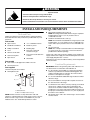
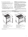
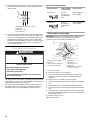
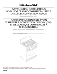
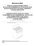
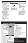
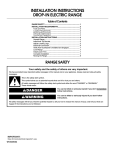
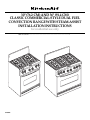
30" (76.2 CM) AND 36" (91.4 CM)
CLASSIC COMMERCIAL-STYLE DUAL FUEL
CONVECTION RANGE WITH STEAM-ASSIST
INSTALLATION INSTRUCTIONS
for residential use only
Table of Contents............................................................................................................ 2
FFO
FFO
F FO
FFO
FFO
FFO
F FO
FFO
9758978
TABLE OF CONTENTS
RANGE SAFETY .........................................................................3
INSTALLATION REQUIREMENTS ................................................4
Tools and Parts ............................................................................4
Location Requirements ................................................................4
Electrical Requirements ...............................................................7
Gas Supply Requirements ...........................................................7
INSTALLATION INSTRUCTIONS ..................................................9
Unpack Range..............................................................................9
Level Range..................................................................................9
Install Anti-Tip Bracket.................................................................9
Make Electrical Connection .......................................................10
Attach Backguard or Island Trim ...............................................11
Make Gas Connection ...............................................................11
Electronic Ignition System .........................................................12
Reinstall Bottom Vent ................................................................13
Complete Installation .................................................................13
WIRING DIAGRAMS.....................................................................13
2
RANGE SAFETY
Your safety and the safety of others are very important.
We have provided many important safety messages in this manual and on your appliance. Always read and obey all safety
messages.
This is the safety alert symbol.
This symbol alerts you to potential hazards that can kill or hurt you and others.
All safety messages will follow the safety alert symbol and either the word “DANGER” or “WARNING.”
These words mean:
DANGER
WARNING
You can be killed or seriously injured if you don't immediately
follow instructions.
You can be killed or seriously injured if you don't follow
instructions.
All safety messages will tell you what the potential hazard is, tell you how to reduce the chance of injury, and tell you what can
happen if the instructions are not followed.
WARNING: For your safety, the information in this manual must be followed to minimize
the risk of fire or explosion, or to prevent property damage, personal injury, or death.
– Do not store or use gasoline or other flammable vapors and liquids in the vicinity of this
or any other appliance.
– WHAT TO DO IF YOU SMELL GAS:
• Do not try to light any appliance.
• Do not touch any electrical switch; do not use any phone in your building.
• Clear the room, building, or area of all occupants.
• Immediately call your gas supplier from a neighbor's phone. Follow the gas supplier's
instructions.
• If you cannot reach your gas supplier, call the fire department.
– Installation and service must be performed by a qualified installer, service agency, or
the gas supplier.
In the State of Massachusetts, the following installation instructions apply:
■
■
■
Installations and repairs must be performed by a qualified or licensed contractor, plumber, or gasfitter qualified or licensed by
the State of Massachusetts.
If using a ball valve, it shall be a T-handle type.
A flexible gas connector, when used, must not exceed 3 feet.
3
WARNING
Tip Over Hazard
A child or adult can tip the range and be killed.
Connect anti-tip bracket to wall behind range.
Reconnect the anti-tip bracket, if the range is moved.
Failure to follow these instructions can result in death or serious burns to children and adults.
INSTALLATION REQUIREMENTS
■
Backguard and attachment screws (7).
NOTE: The backguard included with the range is required if
installed with less than 1" (2.5 cm) clearance from a
combustible rear wall.
■
Island trim and attachment screws (3).
NOTE: The island trim included with the range may be used if
installed with 1" (2.5 cm) clearance from a combustible rear
wall or with 0" (0 cm) clearance from a noncombustible rear
wall.
■
LP conversion kit.
NOTE: The cooktop is manufactured for use with Natural gas.
To convert to LP gas, see the gas conversion instructions
provided in the literature package.
Tools and Parts
Gather the required tools and parts before starting installation.
Read and follow the safety instructions provided with any tools
listed here.
Tools needed
■
Tape measure
■
¹⁵⁄₁₆" combination wrench
■
Flat-blade screwdriver
■
Marker or pencil
■
Phillips screwdriver
■
Masking tape
■
Level
■
■
Hand or electric drill
Pipe-joint compound
resistant to LP gas
■
Channel lock pliers
■
Noncorrosive leak-detection
solution
■
Pipe wrench
■
Stud finder
Parts needed
■
A UL listed or CSA approved conduit connector
■
UL listed wire nuts
Check local codes and consult gas supplier. Check existing gas
supply and electrical supply. See “Electrical Requirements” and
“Gas Supply Requirements” sections.
All electrical connections should be made by a licensed, qualified
electrical installer.
Location Requirements
Parts supplied
Check that all parts are included.
■ Anti-tip bracket kit
1¾"
(4.4 cm)
1"
(2.5 cm)
A
IMPORTANT: Observe all governing codes and ordinances. Do
not obstruct flow of combustion and ventilation air.
■ It is the installer’s responsibility to comply with installation
clearances specified on the model/serial rating plate. The
model/serial rating plate is located on the vertical surface
below the control panel on the right.
■
It is recommended that a 600 CFM range hood be installed
above the range.
■
Recessed installations must provide complete enclosure of
the sides and rear of the range.
■
To eliminate the risk of burns or fire by reaching over heated
surface units, cabinet storage space located above the
surface units should be avoided. If cabinet storage is to be
provided, the risk can be reduced by installing a range hood
that projects horizontally a minimum of 5" (12.7 cm) beyond
the bottom of the cabinets.
■
All openings in the wall or floor where range is to be installed
must be sealed.
B
A. Anti-tip bracket
B. #10 x 2" Phillips head screws (2)
NOTE: Brackets must be securely attached to wall stud.
Thickness of finished wall may require longer screws to anchor
bracket to wall. Longer screws are available from your local
hardware store. See “Install Anti-Tip Bracket” section.
4
■
Do not seal the range to the side cabinets.
■
Cabinet opening dimensions that are shown must be used.
Given dimensions are minimum clearances.
■
The wall anti-tip bracket must be installed. To install the antitip bracket shipped with the range, see “Install Anti-Tip
Bracket” section.
■
Grounded electrical supply is required. See “Electrical
Requirements” section.
■
Proper gas supply connection must be available. See “Gas
Supply Requirements” section.
■
Contact a qualified floor covering installer to check that the
floor covering can withstand at least 200°F (93°C). Use an
insulated pad or ¼" (0.64 cm) plywood over carpet and under
range if installing range over carpeting.
IMPORTANT: Some cabinet and building materials are not
designed to withstand the heat produced by the oven for baking
and self-cleaning. Check with your builder or cabinet supplier to
make sure that the materials used will not discolor, delaminate or
sustain other damage.
Mobile Home - Additional Installation Requirements
The installation of this range must conform to the Manufactured
Home Construction and Safety Standard, Title 24 CFR, Part 3280
(formerly the Federal Standard for Mobile Home Construction
and Safety, Title 24, HUD Part 280). When such standard is not
applicable, use the Standard for Manufactured Home
Installations, ANSI A225.1/NFPA 501A or with local codes.
Mobile home installations require:
■ When this range is installed in a mobile home, it must be
secured to the floor during transit. Any method of securing
the range is adequate as long as it conforms to the standards
listed above.
Product Dimensions
30" (76.2 cm) models
36" (91.7 cm) models]
A
A
G
G
F FO
FFO
B
FFO
FFO
B
FFO
F FO
FFO
FFO
C
C
F
F
D
E*
A. Backguard (required for some installations)
B. 45" (114.3 cm) overall height
C. 36" (91.4 cm) cooktop height with feet loosened ¾ turn
D. 30" (76.2 cm) width
E. 26½" (67.3 cm) width with control panel, see NOTE*
F. ¼" (6.4 cm) spacer
G. 9¼" (23.5 cm) backguard height
E*
D
A. Backguard (required for some installations)
B. 45" (114.3 cm) overall height
C. 36" (91.4 cm) cooktop height with feet loosened ¾ turn
D. 36" (91.4 cm) width
E. 26½" (67.3 cm) width with control panel, See NOTE*
F. ¼" (6.4 cm) spacer
G. 9¼" (23.5 cm) backguard height
*When installed in a 24" (61 cm) base cabinet with 25" (63.5 cm) countertop; front of oven door protrudes 1⁷⁄₈" (4.8 cm) beyond
24" (61 cm) base cabinet.
5
Installation Clearances
Cabinet opening dimensions shown are for 25" (64 cm) countertop depth, 24" (61 cm) base cabinet depth and 36" (91.4 cm)
countertop height.
30" (76.2 cm) models
36" (91.4 cm) models
O
O
M*
N
M*
N
L
L
K
K
A
A
J
B
D
J
I
B
H
E
D
G
F
I
H
E
G
F
C
C
A. 18" (45.7 cm) upper cabinet to countertop
B. 30" (76.2 cm) model: B = 22" (55.9 cm)
C. Junction box to be located in this shaded area
D. 4" (10.2 cm)
E. 20" (50.8 cm)
F. 12" (30.5 cm)
G. 5½" (14 cm)
H. Gas line opening to be located in this shaded area
I. 3½" (8.9 cm)
J. 8" (20.3 cm)
K. 30" (76.2 cm) model: K = 30¼" (76.8 cm)
L. 4" (10.2 cm) min. clearance from both sides of range to side
wall or other combustible material
M. For minimum clearance to top of range, see NOTE*
N. 30" (76.2 cm) model: 30" (76.2 cm) min. upper cabinet width
O. 13" (33 cm) max. upper cabinet depth
A. 18" (45.7 cm) upper cabinet to countertop
B. 36" (91.4 cm) model: B = 28" (71.1 cm)
C. Junction box to be located in this shaded area
D. 4" (10.2 cm)
E. 20" (50.8 cm)
F. 12" (30.5 cm)
G. 5½" (14 cm)
H. Gas line opening to be located in this shaded area
I. 3½" (8.9 cm)
J. 8" (20.3 cm)
K. 36" (91.4 cm) model: K = 36¼" (92.1 cm)
L. 4" (10.2 cm) min. clearance from both sides of range to side
wall or other combustible material
M. For minimum clearance to top of range, see NOTE*
N. 36" (91.4 cm) model: 36" (91.4 cm) min. upper cabinet width
O. 13" (33 cm) max. upper cabinet depth
*NOTE: Minimum Clearances
30" (76.2 cm) models: 36" (91.4 cm) minimum clearance
36" (91.4 cm) models: 42" (106.7 cm) minimum clearance
When bottom of wood or metal cabinet is protected by not less than ¹⁄₄" (0.64 cm) flame retardant millboard covered with not less than
No. 28 MSG sheet steel, 0.015" (0.4 mm) stainless steel, 0.024" (0.6 mm) aluminum or 0.020" (0.5 mm) copper.
30" (76.2 cm) models: 42" (106.7 cm) minimum clearance
36" (91.4 cm) models: 48" (121.9 cm) minimum clearance
Between the top of the cooking platform and the bottom of an unprotected wood or metal cabinet.
If installing a hood or a microwave hood combination above the range, follow the hood instructions for dimensional clearances above
the cooktop surface.
6
■
Electrical Requirements
If codes permit and a separate ground wire is used, it is
recommended that a qualified electrical installer determine that
the ground path and wire gauge are in accordance with local
codes.
If codes permit and a separate ground wire is used, it is
recommended that a qualified electrician determine that the
ground path is adequate.
Do not use an extension cord.
Make sure that the electrical connection and wire size are
adequate and in conformance with the National Electrical Code,
ANSI/NFPA 70-latest edition and all local codes and ordinances.
A copy of the above code standards can be obtained from:
National Fire Protection Association,
One Batterymarch Park,
Quincy, MA 02269
If the house has aluminum wiring, follow the procedure
below:
a) Connect the aluminum wiring to the copper wiring using
special connectors designed and UL listed for joining
copper to aluminum. Follow the electrical connector
manufacturer’s recommended procedure.
b) Aluminum/copper connection must conform with local
codes and industry-accepted wiring practices.
Gas Supply Requirements
WARNING
Electrical Connection
To properly install your range, you must determine the type of
electrical connection you will be using and follow the instructions
provided for it here.
■ Do not ground to a gas pipe.
Explosion Hazard
Use a new CSA International approved gas supply line.
Install a shut-off valve.
Securely tighten all gas connections.
■
Check with a qualified electrical installer if you are not sure
the range is properly grounded.
■
Do not have a fuse in the neutral or ground circuit.
■
Range must be connected to the proper electrical voltage
and frequency as specified on the model/serial number rating
plate. (The model/serial number rating plate is located on the
vertical surface below the control panel on the right.)
Examples of a qualified person include:
licensed heating personnel,
authorized gas company personnel, and
authorized service personnel.
■
Range must be connected to a grounded metal, permanent
wiring system.
Failure to do so can result in death, explosion, or fire.
■
A 4-wire or 3-wire, single phase, 240 volt, 60 Hz., AC only
electrical supply is required on a separate, 30-amp circuit,
fused on both sides of the line.
■
A time-delay fuse or circuit breaker is recommended. The
fuse size must not exceed the circuit rating of the range
specified on the model/serial rating plate located on the
horizontal surface below the control panel.
■
The range can be connected directly to the fused disconnect
(or circuit breaker box) through flexible, armored or
nonmetallic sheathed, copper or aluminum cable. The
flexible, armored cable extending from the fuse box or circuit
breaker box should be connected directly to the junction box.
See “Make Electrical Connection.”
■
Locate the junction box to allow as much slack as possible
between the junction box and the range so that the range can
be moved if servicing is ever necessary. Do not cut the
conduit.
■
A UL listed conduit connector must be provided at each end
of the power supply cable (at the cooktop and at the junction
box).
■
Wire sizes and connections must conform with the rating of
the range (30 amps).
If connected to LP, have a qualified person make sure
gas pressure does not exceed 14" (36 cm) water
column.
Observe all governing codes and ordinances.
IMPORTANT: This installation must conform with all local codes
and ordinances. In the absence of local codes, installation must
conform with American National Standard, National Fuel Gas
Code ANSI Z223.1 - latest edition.
IMPORTANT: Range cooktop must be connected to a regulated
gas supply.
Type of Gas
Natural Gas:
This range is design-certified by CSA International for use with
Natural gas or, after proper conversion, for use with LP gas.
■ This range is factory set for use with Natural gas. The model/
serial rating plate located on the right vertical surface of the
oven door frame has information on the types of gas that can
be used. If the types of gas listed do not include the type of
gas available, check with the local gas supplier.
LP Gas conversion:
Conversion must be done by a qualified service technician.
No attempt shall be made to convert the appliance from the gas
specified on the model/serial rating plate for use with a different
gas without consulting the serving gas supplier. To convert to LP
gas, use the LP gas conversion kit provided with your range. The
parts for this kit are in the literature package supplied with the
range.
7
Gas Supply Line
■
Gas Pressure Regulator
Provide a gas supply line of ¾" (1.9 cm) rigid pipe to the
range location. A smaller size pipe on longer runs may result
in insufficient gas supply. Pipe-joint compounds that resist
the action of LP gas must be used. Do not use TEFLON®†
tape. With LP gas, piping or tubing size can be ½" (1.3 cm)
minimum. Usually, LP gas suppliers determine the size and
materials used in the system.
Flexible metal appliance connector:
■
If local codes permit, a new CSA design-certified,
4 - 5 ft (122 - 152.4 cm) long, ⁵⁄₈" (1.6 cm) or
¾" (1.9 cm) I.D., flexible metal appliance connector may
be used for connecting range to the gas supply line.
The gas pressure regulator supplied with this range must be
used. The inlet pressure to the regulator should be as follows for
proper operation:
Natural Gas:
Minimum pressure: 6" (15.2 cm) WCP
Maximum pressure: 14" (35.6 cm) WCP
LP Gas:
Minimum pressure: 11" (27.9 cm) WCP
Maximum pressure: 14" (35.6 cm) WCP
Contact local gas supplier if you are not sure about the inlet
pressure.
Burner Input Rating - Altitude
■
A ½" (1.3 cm) male pipe thread is needed for connection
to the female pipe threads of the inlet to the appliance
pressure regulator.
■
Do not kink or damage the flexible metal tubing when
moving the range.
Gas Supply Pressure Testing
Rigid pipe connection:
The rigid pipe connection requires a combination of pipe
fittings to obtain an in-line connection to the range. The rigid
pipe must be level with the range connection. All strains must
be removed from the supply and fuel lines so range will be
level and in line.
■
Must include a manual shutoff valve:
The supply line must be equipped with a manual shutoff
valve. This valve should be located in the same room but
external to the range. It should be in a location that allows
ease of opening and closing. Do not block access to shutoff
valve. The valve is for turning on or shutting off gas to the
range.
B
A
C
A. Gas supply line
B. Shutoff valve “open” position
C. To range
†®TEFLON is a registered trademark of E.I. Du Pont De Nemours and Company.
8
Input ratings shown on the model/serial rating plate are for
elevations up to 2,000 ft (609.6 m).
For elevations above 2,000 ft (609.6 m), ratings are reduced at a
rate of 4% for each 1,000 ft (304.8 m).
Line pressure testing above ½ psi gauge (14" WCP)
The range and its individual manual shutoff valve must be
disconnected from the gas supply piping system during any
pressure testing of that system at test pressures greater than
½ psi (3.5 kPa).
Line pressure testing at ½ psi gauge (14" WCP) or lower
The range must be isolated from the gas supply piping system by
closing its individual manual shutoff valve during any pressure
testing of that system at test pressures equal to or less than
½ psi (3.5 kPa).
INSTALLATION INSTRUCTIONS
Unpack Range
Install Anti-Tip Bracket
WARNING
WARNING
Excessive Weight Hazard
Use two or more people to move and install range.
Failure to do so can result in back or other injury.
1. Remove shipping materials, tape and protective film from
range. Keep shipping pallet under range. Remove oven racks,
grates and parts package from inside oven.
2. Remove the 2 screws on each side of the top of the bottom
vent. Slide the vent down and pull toward you. Lay this part to
the side to avoid scratching the stainless steel.
B
Tip Over Hazard
A child or adult can tip the range and be killed.
Connect anti-tip bracket to wall behind range.
Reconnect the anti-tip bracket, if the range is moved.
Failure to follow these instructions can result in death
or serious burns to children and adults.
A
A. Bottom vent
B. Remove these screws
3. Lay a piece of cardboard from side packing on the floor
behind range. Using 2 or more people, firmly grasp each side
of range. Lift range up about 3" (8 cm) and move it back until
range is off shipping pallet. Set range on cardboard to avoid
damaging floor.
Level Range
1. Choose the correct anti-tip bracket for your installation.
■ If the wall behind the range has no baseboard or has a
baseboard up to ³⁄₈" (0.95 cm) thick, use the shorter
1" (2.5 cm) anti-tip bracket.
■
If the wall behind the range has a baseboard thicker than
³⁄₈" (0.95 cm), use the longer 1¾" (4.4 cm) anti-tip bracket.
2. Locate a stud on the wall behind the range. Measure the
distance from top of rear brace to floor.
A
1. Move range close to the cabinet opening.
2. Place a rack in oven.
3. Place level on rack, first side to side, then front to back.
C
B
D
4. If the range is not level, adjust the feet up or down. Turn
leveling leg sleeves to level range and to raise or lower range
to the desired countertop height.
A
A. Rear brace
B. Top of rear brace to floor
C. Top of rear brace
D. Floor
3. Add ⁵⁄₁₆" (0.79 cm) to the measurement from Step 2. This will
allow the anti-tip bracket to slide over rear brace.
A. Leveling leg sleeves
NOTE: Oven must be level for satisfactory baking performance.
9
4. Using the final measurement from Step 3, measure from the
floor up and mark a horizontal line on the wall where a wall
stud is located.
A
B
D
C
Electrical Connection Options
If your home has:
And you will be
connecting to:
Go to Section:
4-wire direct
A fused
disconnect or
circuit breaker
box
4-Wire Cable from
Power Supply
A fused
disconnect or
circuit breaker
box
3-Wire Cable from
Power Supply
5"
(12.7 cm)
3-wire direct
A. Horizontal line marked from Step 4.
B. Wall stud
C. Mounting screws
D. Anti-tip bracket
3¹⁄₂"
(8.9 cm)
4-Wire Cable from Power Supply
5. Position top of anti-tip bracket at line marked in Step 4 and
mark holes. Drill two ¹⁄₈" holes at the positions marked on the
wall. Use screws provided to fasten anti-tip bracket to wall.
Anti-tip bracket must be mounted securely to stud in wall
behind the range. Depending on thickness of the wall, longer
screws may be required. Longer screws are available from
your local hardware store.
IMPORTANT: Use the 4-wire cable from power supply where
local codes do not permit connecting the frame-ground
conductor to the neutral (white) junction box wire.
A
B
Make Electrical Connection
E
F
G
WARNING
Electrical Shock Hazard
Disconnect power before servicing.
C
H
D
I
A. Cable from power supply
B. Red wires
C. Green (or bare) ground wires
D. 4-Wire cable from range
E. Junction box
F. White wires
G. UL listed wire nuts
H. Black wires
I. UL listed or CSA approved
conduit connector
Use 8 gauge solid copper wire.
Electrically ground range.
Failure to follow these instructions can result in death,
fire, or electrical shock.
This range must be connected to a grounded, metallic permanent
wiring system or a ground connector should be connected to the
ground terminal or wire lead on the range.
This range is manufactured with a frame connected, green or
bare ground wire. Connect the range cable to the junction box
through the UL listed or CSA approved conduit connector.
10
1. Disconnect power.
2. Remove junction box cover if present.
3. Connect the flexible armored cable from the range to the
junction box using a UL listed or CSA approved conduit
connector.
4. Tighten screws on conduit connector if present.
5. Connect the two black wires together using the UL listed wire
nuts.
6. Separate the factory-crimped bare and white range wires.
7. Connect the two white wires together using the UL listed wire
nuts.
8. Connect the green or bare ground wire from the range cable
to the green or bare grounded wire (in the junction box) using
the UL listed wire nuts.
9. Install junction box cover.
10. Reconnect power.
Attaching the Backguard
3-Wire Cable from Power Supply
36" model shown
IMPORTANT: Use the 3-wire cable from power supply where
local codes permit connecting the frame-ground conductor to
the neutral (white) junction box wire.
A
B
C
A
G
H
D
E
F
I
A. 3 front screws (4 rear screws required but not shown)
Attaching the Island Trim
A. Cable from power supply
B. Junction box
C. Red wires
D. White wire (from power supply)
E. White and green (or bare) grounding
wires (from range) - factory crimped
F. 4-wire cable from range
G. Black wires
H. UL listed wire nuts
I. UL listed or CSA approved
conduit connector
1. Disconnect power.
2. Remove junction box cover if present.
3. Connect the flexible armored cable from the range to the
junction box using a UL listed or CSA approved conduit
connector.
4. Tighten screws on conduit connector if present.
5. Connect the two black wires together using UL listed wire
nuts.
6. Connect the two red wires together using UL listed wire nuts.
7. Connect the factory-crimped bare and white range cable
wires to the white (neutral) wire in the junction box using UL
listed wire nuts.
8. Install junction box cover.
9. Reconnect power.
Attach Backguard or Island Trim
WARNING
Excessive Weight Hazard
Use two or more people to move and install range.
Failure to do so can result in back or other injury.
36" model shown
A
A. Center hole not used
4. Using 2 or more people, tip the range back so that the front
feet lift off the ground. Slide range toward the wall until the
rear brace is under the anti-tip bracket. Stand range up,
making sure the anti-tip bracket catches the rear brace.
Make Gas Connection
1. Assemble flexible connector from gas supply pipe to pressure
regulator located in the middle front of the range.
2. Apply pipe-joint compound made for use with LP gas to the
smaller thread ends of the flexible connector adapters (see B
and G in following illustration).
3. Attach one adapter to the gas pressure regulator and the
other adapter to the gas shutoff valve. Tighten both adapters.
4. Use a ¹⁵⁄₁₆" combination wrench and channel lock pliers to
attach the flexible connector to the adapters. Check that
connector is not kinked.
A
B
C
1. Using 2 or more people, move range close to cabinet
opening.
2. Remove cardboard or hardboard from under range. Move
range into final position.
3. Attach the backguard or island trim as required for your
installation. See “Tools and Parts.” Attachment screws are
included in the literature package.
D
E
H
A. Gas pressure regulator
B. Use pipe-joint compound
C. Adapter (must have ½" male
pipe thread)
D. Flexible connector
G
F
E. Manual gas shutoff valve
F. ½" or ¾" gas pipe
G. Use pipe-joint compound
H. Adapter
11
Complete Connection
1. Open the manual shutoff valve in the gas supply line. The
valve is open when the handle is parallel to the gas pipe.
A
B
A. Closed valve
B. Open valve
2. Test all connections by brushing on an approved
noncorrosive leak-detection solution. Bubbles will show a
leak. Correct any leak found.
3. Remove cooktop burner caps, grates and simmer plate from
parts package. Align notches in burner caps with pins in
burner base. Burner caps should be level when properly
positioned. If burner caps are not properly positioned,
surface burners will not light. Place burner grates over
burners and caps.
D
Adjust Flame Height
Adjust the height of top burner flames. The cooktop “low” burner
flame should be a steady blue flame approximately ¼" (0.64 cm)
high.
A
B
A. Low flame
B. High flame
The flame can be adjusted using the adjustment screw in the
center of the valve stem. The valve stem is located directly
underneath the control knob.
C
B
A
A
A. Adjustment screw
A. Burner base
B. Burner cap
C. Burner grate
D. Simmer plate
4. Turn on power supply. “PF” should appear on the clock
display. For further information, please refer to the user
instructions located in the Use and Care Guide.
Electronic Ignition System
Initial lighting and gas flame adjustments
Cooktop and oven burners use electronic igniters in place of
standing pilots. When the cooktop control knob is turned to the
“LITE” position, the system creates a spark to light the burner.
This sparking continues, as long as the control knob is turned to
“LITE.”
Check Operation of Cooktop Burners
Push in and turn each control knob to the “LITE” position.
The flame should light within 4 seconds. The first time a burner is
lit it may take longer than 4 seconds to light because of air in the
gas line.
If burners do not light properly:
■
Turn cooktop control knob to the “OFF” position.
■
Check that the range is plugged in and the circuit breaker has
not tripped or the fuse blown.
■
Check that the gas shutoff valves are set to the “open”
position.
■
Check that burner caps are properly positioned on burner
bases.
Repeat start-up. If a burner does not light at this point, contact
your dealer or authorized service company for assistance.
12
If the “low” flame needs to be adjusted:
1. Remove the control knob.
2. Hold the knob stem with a pair of pliers. Use a small flatblade screwdriver to turn the screw located in the center of
the control knob stem until the flame is the proper size.
3. Replace the control knob.
4. Test the flame by turning the control from “LO” to “HI,”
checking the flame at each setting.
Check Operation of Oven Element
1. Turn oven selector to BAKE. Default temperature appears in
the temperature display.
2. Press ENTER. The display reads “PrE” when the oven
temperature begins to rise.
3. Wait 2 minutes, open oven door and hold hand above oven
floor and feel for heat. Do not touch oven floor. Press
CANCEL and turn oven selector to RESET.
Check Operation of Oven Broil Element
1. Close the oven door.
2. Turn oven selector to BROIL. “HI” will appear in the
temperature display.
3. Press ENTER. Look through oven window. The top element
should glow red, and heat should be radiating out of the door.
Press CANCEL and turn oven selector to RESET.
Check Operation of Steam Assist Technology
1. Turn oven selector to “SELECT STEAM.”
The indicator light will flash next to “HIGH STEAM.”
2. Pour water into the water inlet until the “HALF” indicator
lights up.
3. Press ENTER and default temperature appears in the display.
4. Press ENTER and the default cook time appears in the
display.
Set the cook time to 10 minutes.
5. The display will indicate “LoAd.” Open and close the oven
door.
6. After the 10 minutes counts down, open the oven door. The
cavity should be warm and moist.
7. Press CANCEL and turn the oven selector and RESET.
If oven does not operate:
■
Check that power supply is turned on.
■
Check that the range is plugged in and the circuit breaker has
not tripped or the household fuse blown.
Repeat start-up. If the oven still does not operate at this point,
contact your dealer or authorized service company for
assistance.
Install Burner Grates
Place burner grates over burner caps. The simmer plate may sit
on one of the grates or be stored for future use.
Reinstall Bottom Vent
1. Insert lower vent tabs into the slots on the front trim.
2. Push vent upward until the holes line up at top of vent.
3. Reattach the vent using the 4 screws.
Complete Installation
1. Check that all parts are now installed. If there is an extra part,
go back through the steps to see which step was skipped.
2. Check that range is correctly positioned in countertop cutout
and that the range is level. See “Level Range.”
3. Check that the specified distances to cabinet surfaces were
maintained. See “Location Requirements.”
4. Check that burner caps are positioned properly on sealed
burner bases.
5. Check that backguard or island trim is installed. (If horizontal
clearance to combustible materials behind cooking surface is
less than 1" [2.5 cm]).
6. Check that the range is connected only to the type of gas for
which it is certified for use.
7. Use a mild solution of liquid household cleaner and warm
water to remove waxy residue caused by protective shipping
material. Dry thoroughly with a soft cloth. For more
information, see the “Range Care” section of the Use and
Care Guide.
8. Read “Range Use” in the range Use and Care Guide.
9. Turn on surface burners and oven. See your Use and Care
Guide for specific instruction on range operation.
10. Once the oven has cooled down, you may drain the water
reservoir. Read “Water Reservoir Drain Operation” in the Use
and Care Guide.
If range does not operate, check the following:
■
Household fuse has not blown or circuit breaker has not
tripped.
■
Gas valves are turned to the “ON” position.
■
Electrical supply is connected.
■
See “Troubleshooting” in the Use and Care Guide.
B
A
A. Bottom vent
B. Reattach these screws
WIRING DIAGRAMS
CAUTION: Label all wires prior to disconnection when servicing controls. Wiring errors can cause improper and dangerous operation.
Cooktop Schematic
30" (76.2 cm) model
36" (91.4 cm) model
N
L1
W
BK
L2
L1
N
R
W
BK
R
G
W
W
GND
R
VALVE SWITCHES
R
W
W
GND
L2
G
W
W
SPARK
MODULE
SPARK MODULE
Y or BR
(4) PLCS
VALVE SWITCHES
Y OR BR (6) PLCS
IGNITER ELECTRODES
IGNITER ELECTRODES
13
Oven Schematic
CLASSIC COMMERCIAL STYLE OVEN WITH STEAM ASSIST
WIRING DIAGRAM
STEAM BOARD
APPLIANCE
MANAGER
*
(
)
*Blower remains off until oven reaches 190°F (88°C) and may continue running up to 45 minutes after oven has turned off.
NOTE: Circuit is shown in standby/off mode with oven door closed.
14
Notes
15
9758978
© 2005. All rights reserved.
® Registered Trademark/TM Trademark of KitchenAid, U.S.A.
7/05
Printed in U.S.A.