1
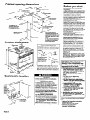
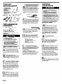
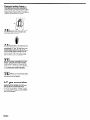
Part No. 3186508 Rev. A
A
l
l
l
l
WARNING
ALL RANGES CAN
TIP
INJURY TO PERSONS
COULD RESULT
INSTALL ANTI-TIP
DEVICE PACKED
WITH RANGE
SEE INSTALLATION
INSTRUCTIONS
IMPORTANT:
Read and save
these instructions.
IMPORTANT:
Installer: Leave installation
Instructions
with the homeowner.
Homeowner: Keep Installation Instructions
for future reference.
Save Installation Instructions for local
electrical inspector’s use.
/Electric
Thermal/Convect ion
Slide-in Range
with self-cleaning oven
Cabinet opening dimensions
Before you start...
Read electrical, gas and carpentry
instructions.
Proper installation is your responsibility.
Fdr minimum clearance to the
top of the cooktop, see Note.“”
A
qualified technician should install this range.
Make sure you have everything necessary
for correct installation. It is the customer’s
responsibility to make sure that the
countertop has been properly prepared and
that the installation clearances specified on
the serial/rating plate are met. The
serial/rating plate can be found on the oven
frame behind the oven door.
Check location where range will be
installed. The location should be away from
strong draft areas, such as windows, doors
and strong heating vents or fans. The range
should be located for convenient use in the
kitchen. Installation must provide complete
enclosure of the sides and rear of range.
ALL OPENINGS IN THE WALL OR FLOOR
WHERE RANGE IS TO BE INSTALLED
MUST BE SEALED.
Electrical ground is required. See
“Electrical requirements.”
Proper gas supply connection must be
available. See “Gas supply requirements.”
Cabinet opening dimensions that are
shown must be used. Given dimensions
provide required 0” clearance.
Cabinet construction: This appliance is
designed for use in a base cabinet with a
depth of 24”. The maximum depth for
overhead cabinets is 13”. The minimum
vertical clearance between the cooking
surface and the overhead cabinets is 30”.
Overhead cabinets installed at either side of
the appliance must be a minimum of 18”
above the cooking surface. The minimum
horizontal distance between the overhead
cabinets is 30”.
Do Not seal range
to side cabinets.
The range MUST be
secured to cabinet with
four screws provided.
For detailed instructions,
see Panel D.
718” min. required
between cutout and
door or hinge.
countertop
Product dimensions
30”
\
height
covered with not less than No.28
MSG sheet steel, 0.015” stainless
steel, 0.024” aluminum or 0.020”
copper.
36” min. clearance between the
top of the cooking platform and
the bottom of an unprotected
wood or metal cabinet.
Countertop preparation:
Front edges: You may need to shave or
cut the trim of formed or metal front-edged
countertops to clear the 30” width of
cook-top.
If countdrtop
extends
more than l-118”
beyond cabinet front,
additional notching of
edge is required to
clear step of end cap.
Countertop must be level. Place level on
countertop, first side to side; then front to
back. If countertop is not level, range will not
be level. Oven must be level for satisfactory
baking conditions.
recessed
depth
Gas/electric
Locate
electrical
location
\
or floor within
this shaded area.
Panel A
Fire Hazard
Do Not obstruct the flow of combustion
and ventilation air.
Personal Injury Hazard
To eliminate the risk of burns or fire,
avoid installing cabinet storage above the
cooking surface. If cabinets are already
installed, reduce the hazard of reaching
over a heated cooking surface by
installing a range hood. The range hood
should extend a minimum of 5 inches out
from the bottom front of the cabinets.
Reaching over a heated cooking surface
could result in a serious burn.
Electrical Shock Hazard
It is the customer’s responsibility:
l To contact
a qualified electrical installer.
l To assure that the electrical
installation
is adequate and in conformance with
National Electrical Code, ANSVNFPA
70 - latest edition*, and all local codes
and ordinances.
Failure to do so could result in electrical
shock or other personal injury.
Important:
Observe all governing codes and
ordinances. Failure to meet codes
and ordinances could lead to fire
or electrical shock.
I
JI
WARNING: If the information in
this manual is not followed
exactly, a fire or explosion may
result causing property damage,
personal injury
- or death.
I- Do Not store or use gasoline OI
other flammable vapors and
liquids in the vicinity of this or
any other appliance.
- WHAT TO DO IF YOU SMELL
GAS
l Do Not try to light any
appliance.
l Do Not touch
any electrical
switch; Do Not use any phone
in your building.
l Immediately
call your gas
supplier from a neighbor’s
phone. Follow the gas
supplier’s instructions.
l If you cannot
reach your gas
supplier, call the fire
department.
- Installation and service must
be performed by a qualified
installer, service agency or the
gas supplier.
Copies of the standards listed may be obtained
from:
National Fire Protection Association
Batterymarch Park
Quincy, Massachusetts 02269
**American Gas Association
1515 Wilson Boulevard
Arlington, Virginia 22209
l
Tools and
materials needed
for installation:
gas line shutoff valve
L.P.-resistant
pipe-joint
compound
A.G.A. design-certified
flexible metal
connector (4-5 feet)
2 flare union adapters for
connection
to pressure
regulator (112” NPT x
112” or 314 ’ I.D.)
l
l
l
l
318” ratchet
Electrical
requirements
If local codes permit, a new A.G.A.
design-certified, 4-5 foot long, l/2” or
314” I.D., flexible metal appliance
connector is recommended for connecting this
range to the gas supply line. Do Not kink or
damage the flexible tubing when moving the
range. A l/2” male pipe thread is needed for
connection to pressure regulator female pipe
threads.
The supply line shall be equipped with
an approved shutoff valve. This valve
n
is for turning on or shutting off gas to
the appliance. This valve should be located in
the same room, but external to the range, and
should be in a location that allows ease of
opening and closing. Do Not block access to
shutoff valve.
IF
screwdriver
Parts supplied for
installation:
m-+-Jem
4 screws
Gas supply
requirements
Observe all governing codes and
ordinances.
Fire Hazard
Range must be connected to a
regulated gas supply.
L.P. gas supply must Not exceed a
pressure of 14” water column. This
must be checked by a qualified
technician before installing the range.
Do Not use an open flame to test for
leaks from gas connections.
New, A.G.A.-design-certified, flexible
metal gas line connector should be
used when codes permit.
Failure to follow these instructions could
result in a fire, explosion or personal
injury.
l
l
l
Electrical Shock Hazard
l Electrical
ground is required on this
appliance.
l Do Not ground
to a gas supply pipe.
l Do Not have a fuse in the neutral
or
grounding circuit. A fuse in the neutral
or grounding circuit could result in an
electrical shock.
l Check with a qualified
electrician if you
are in doubt as to whether the appliance
is properly grounded.
Failure to follow these instructions could
result in serious injury or death.
If codes permit and a separate grounding
wire is used, it is recommended that a
qualified electrician determine that the
grounding path is adequate.
(A
.
El
A three-wire or four-wire, singlephase, 120/240-volt, 60-Hz, AConly electrical supply (or three-wire or fourwire 120/208-volt if specified on the
serial/rating plate) is required on a separate
15-amp circuit, fused on both sides of the line.
A time-delay fuse or circuit breaker is
recommended. The fuse size must not exceed
the circuit rating of the appliance as specified
on the serial/rating plate. The serial/rating
plate is located on the oven frame behind the
oven door.
The regulator must be checked at a
minimum of 1-inch water column
above the set oressure. The inlet
pressure to the regulator should be as follows
for operation:
le
If rigid pipe is used
line, a combination of pipe fittings
must be used to obtain an in-line
connection to the range. All strains must be
removed from the supply and fuel lines so
range will be level and in line.
El
NATURAL GAS:
Set pressure 5 inches
Maximum pressure 14 inches
L.P. GAS:
Set pressure 10 inches
Maximum pressure 14 inches
.
THE RANGE MUST BE
CONNECTED WITH COPPER WIRE
ONLY.
B-l
.
Wire sizes and connections must
conform to the requirements of the
National Electrical Code, ANSVNFPA 70 latest edition* and all local codes and
ordinances for the kilowatt rating of the range.
l
El
This installation must conform with
local codes and ordinances. In the
absence of local codes, installations
must conform with American National Standard,
National Fuel Gas Code ANSI Z223.1- latest
edition.**
.
Input ratings shown on the
serial/rating plate are for elevations up
n
to 2,000 feet. For elevations above
2,000 feet, ratings are reduced at a rate of 4%
for each 1,000 feet above sea level.
[B
Line pressure testing:
Testing above i/2 psi (gauge)
The range and its individual shutoff
valve must be disconnected from the gas supply
piping system during any pressure testing of
that system at test pressures greater than
l/2 psig (3.5 kPa).
Testing at l/2 psi (gauge) or lower
The range must be isolated from the gas supply
piping system by closing its individual manual
shutoff valve during any pressure testing of the
gas supply piping system at test pressures
equal to or less than l/2 psig (3.5 kPa).
I
The appliance should be connected
directly to the fused disconnect or
circuit breaker box through flexible, armored or
non-metallic sheathed, copper cable (with
grounding wire). Locate the junction box to allow
two to three feet of slack in the line so that the
range can be moved if servicing is ever
necessary. Do Not cut the conduit.
A U.L.-listed conduit connector must be
provided at each end of the power supply cable
(at the appliance and at the junction box). Wire
sizes (COPPER WIRE ONLY) and connections
must conform with the rating of the appliance.
El
The wiring diagram is found on Panel
E. The wiring diagram and Tech Sheet
can also be found in a pouch attached to the left
hand underside of the oven. To access, remove
the storage drawer.
n
This range is equipped for use with
NATURAL gas. It is design-certified by
A.G.A. for NATURAL and L.P. gas
with appropriate conversion. The serial/rating
plate, located on the oven frame behind the
oven door, has information on the type of gas
that can be used. If this information does not
agree with the type of gas available, check with
your KitchenAid dealer. Conversion to L.P. gas
requires Kit No. 4175461, available from your
KitchenAid Dealer. This conversion must be
done by a qualified technician.
El
Provide a gas supply line of 3/4” rigid
pipe to the range location. A smaller
size pipe on long runs may result in
insufficient gas supply. Pipe-joint compounds
made for use with L.P. gas must be used. With
L.P. gas, piping or tubing size can be l/2”
minimum. L.P. gas suppliers usually determine
the size and materials used on the system.
Panel B
Electrical
connection
Now start...
With range in kitchen.
Electrical Shock Hazard
Electrical ground is required on this
appliance.
l Do Not connect
to the electrical supply
until appliance is permanently
grounded.
l Disconnect
power to the junction box
before making the electrical
connection.
l This appliance
must be connected to a
grounded, metallic, permanent wiring
system, or a grounding connector
should be connected to the grounding
terminal or wire lead on the appliance.
Failure to do so could result in a fire,
personal injury or electrical shock.
Remove cooktop burner grates and
caps package from shipping box.
Remove hardware package from side of oven.
l
This appliance is manufactured with the white
(neutral) power supply wire and a cabinetconnected green grounding wire twisted
together.
Connect the appliance cable to the junction box
through the U.L.-listed conduit connector.
Complete electrical connection according to
local codes and ordinances.
B-l
’
Remove shipping materials, tape and
protective film from range. Do Not
remove shipping base at this time.
la-l
I
Remove the racks and other parts
from inside the oven.
(81
n
I
v
sp!cer
I
Center range in cutout. Loosen screws and
insert spacers (shipped inside broiler pan and
grill assembly) on each side of control console.
If range does not fit properly, check spacers.
The spacers may need to be cut to fit under the
countertop. Mark with a pencil where each
spacer needs to be cut. Loosen both screws to
remove spacers. Cut across top of each spacer.
Replace spacers and tighten screws. Check that
range fits properly on countertop.
El
n
Insert a nail or 5/32” diameter item in the hole of
the hinges as far as possible. Close the oven
door. Lift oven door off of hinges and set aside.
A. Where local codes permit...
connecting the cabinet-grounding conductor
to the neutral (white) junction box wire:
To reduce the risk of tipping the
appliance, the appliance must be securely
fastened to the cabinet using the four
screws that are provided.
Cable from
power supply
Junction
range
Grounded Neutral
Figure 1
Floor Damage
Before moving range across floor, check
that range is on shipping base or slide
range onto cardboard or hardboard.
Failure to do so could cause damage to
floor covering.
1. Disconnect the power supply.
2. Connect together 3 wires: green and white
appliance cable wires and the neutral (white)
wire in junction box.
3. Connect the two black wires together;
then connect the two red wires together.
See Figure 1.
B. If connecting to a four-wire
electrical system:
(6
Move range close to cabinet cutout.
Make electrical connection. See
’
“Electrical requirements,” and “Electrical
connection,” Panels B and C, for details.
DO NOT connect the cabinet-grounding
conductor to the neutral (white) junction box
wire.
Cable from
I
Personal Injury Hazard
Because of the weight and size of this
range, two or more people are needed to
move and safely install it.
Failure to do so could result in personal
injury.
Use this area to grip.
range
connector
Figure 2
1. Disconnect the power supply.
2. Separate the green and white appliance
cable wires.
3. Connect the white appliance cable wire to the
neutral (white) wire in the junction box.
4. Connect the two black wires together; then
connect the two red wires together.
See Figure 2.
5. Connect the green grounding wire to the
grounding wire in the junction box.
Panel C
(71
Remove and discard shipping base or
cardboard or hardboard from under
range. Lift range up to cabinet opening using
the oven opening as an area to grip.
n
r
@I
a
19.1
screws
Secure range to cabinet using the four screws
through the mounting holes in the front frame of
the oven.
Fire Hazard
Do Not make connection too tight. The
regulator is die cast.
Over-tightening may crack the regulator,
resulting in a gas leak and possible fire or
explosion.
flexible
pressur; regulator
and normally open
valve assembly
connector
manual shutoff valve
(See Steo F on Panel B
for prober location.)
.
ml
I
Open shutoff valve in gas supply
line. Wait a few minutes for gas to
move through the gas line.
Fire Hazard
Do Not use an open flame to test for leaks
from gas connections.
Checking for leaks with a flame may
result in a fire or explosion.
(131
.
l/2” flar& union a>apters
112)
.
All connections
1101
must be wrench-tightened.
’ Assemble the flexible connector
from the manual shutoff valve (or gas supply
line from the shutoff valve) to the pressure
regulator. The pressure regulator is located on
the left, rear lower corner of the range. Use
pipe-joint compound made for use with Natural
and L.P. gas to seal all gas connections. Make
sure flexible connector is not kinked. Seal all
openings in floor or wall where range is
installed.
Use a brush and liquid detergent to
test all connections for leaks.
Bubbles around the connections will indicate a
leak. If a leak appears, shut off gas valve
controls and adjust connections. Then check
connections again. NEVER TEST FOR GAS
LEAKS WITH A MATCH OR OTHER FLAME.
Clean all detergent solution from range.
Replace oven door by fitting both
corners of door over ends of hinges.
Push door evenly and completely onto hinges.
Remove nails from hinges. If door does not
close, you have not pushed door completely
onto hinges. Replace storage drawer.
Place burner grates over burners
and caps. Turn on power supply.
To get the most efficient use
from your new dual fuel range, read
your KitchenAid Use and Care Guide.
Keep Installation instructions and
Guide close to range for easy
reference.
8.
Numbers
correspond
to steps.
Panel D
Electronic Ignition System initial lighting and gas flame adjustments.
Cooktop burners use electronic ignitors in place
of standing pilots. When the cooktop control
knob is turned to the “HI” position, the system
creates a spark to light the burner. This sparking
continues until the burner has a flame.
HI
115.1
Check the operation of the cooktop
burners. Push in and turn each
control knob to the “HI” position. The flame
should light within 4 seconds.
Check each cooktop burner for
proper flame. The small inner cone
should have a very distinct blue flame
approximately l/2” long. The outer cone is not
as distinct as the inner cone. The “LO” (or
simmer) setting of each burner has been factory
set to the lowest setting available to provide
reliable reignition of the burner. If any burner
does not stay lit on the “Lo” setting, contact
your KitchenAid dealer for assistance.
1171
.
If burners do not light properly, turn
cooktop control knob to the “OFF”
position. Check that burner cap is in proper
position. Check the power to the unit and the
circuit breaker or house fuse. Check that gas
valves are set to the “ON” position. Repeat Step
16. If a burner does not light at this point,
contact a KitchenAid dealer for assistance.
(181
.
Refer to your “Use and Care Guide”
and check the ooeration of the oven
bake element and broil element.
L.P. gas conversion
No attempt shall be made to convert the
appliance from the specified gas on the rating
plate for use with a different gas without
consulting the serving gas supplier. Conversion
to L.P. gas requires Kit No. 4175461 available
from your KitchenAid dealer. This conversion
must be done by a qualified technician. Contact
your KitchenAid dealer.
Panel E
If range does not
operate...
l
l
l
Check that the circuit breaker is not tripped or
the house fuse blown.
Check that gas valves are turned to “ON”
position.
A more detailed troubleshooting checklist is
provided in the Use and Care Guide.
NOTE: Refer to Use and Care Guide for
operating instructions and cleaning
For cleaning and
maintenance...
If you need
assistance...
If removing the range is ever necessary for
cleaning or maintenance, shut off gas supply to
range. Disconnect the gas and electrical supply
to the range.
The KitchenAid Consumer Assistance Center
will answer any questions about operating or
maintaining your range not covered in the
Installation Instructions. The KitchenAid
Consumer Assistance Center is open 24 hours
a day, 7 days a week. Just dial l-(800) 4221230 -the
call is free.
Remove the screws holding the range to cabinet
and pull range out only as far as necessary to
disconnect the gas and electrical supply lines.
Remove the range to complete cleaning or
maintenance.
Move
range.
check
range
range back into operating position. Level
Connect the gas line to the range and
for leaks. Replace screws and secure
to cabinet. Reconnect the electric supply.
When you call, you will need the range model
number and serial number. Both numbers can
be found on the serial/rating plate located on the
oven frame behind the oven door.
If you need
service...
In the event that your KitchenAid appliance
should need service, call the dealer from whom
you purchased the appliance or a KitchenAidauthorized service company. A KitchenAidauthorized service company is listed in the
Yellow Pages of your telephone directory under
“Appliances - Household - Major - Service
or Repair.” You can also obtain the service
company’s name and telephone number by
dialing, free, within the continental United
States, the KitchenAid Consumer Assistance
Center telephone number, l-(800) 422-l 230. A
special operator will tell you the name and
number of your nearest KitchenAid-authorized
service company.
Personal Injury/Product Damage Hazard
Do Not step, lean or sit on the range
door.
Failure to follow this instruction could
result in personal injury and/or product
damage.
Maintain the quality built into your KitchenAid
appliance - call a KitchenAid-authorized
service company.
HOME APPLIANCES
Part No. 3 186508 Rev, A
0 1994 KitchenAid.
@ Registered
Trademark
of KitchenAid.
Prepared
by KitchenAid.
St. Joseph,
Michigan
49085
Printed on recycled
paper.
10% post consumer waste/
50% recovered
materials.
Printed in U.S.A.