1
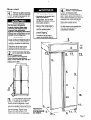
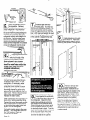
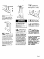
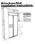
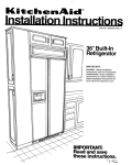
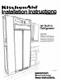
I(ttchenAiid”
Part No. 2000495 Rev. A
42” Built-In
Refrigerator
IMPORTANT:
Installer: Leave Installation
Instructions
with the Homeowner.
Homeowner: Keep Installation
Instructions
for future reference.
Instructions for
local electrical inspector’s use.
Save Installation
=
x
IMPORTANTk
Read and save
these instructions.
Before you start...
Proper installation is your
responsibility.
Make sure you have
everything necessary for correct
installation. It is the responsibility of
the installer to comply with the
installation specifications provided.
The built-in refrtgerator weighs over
500 pounds. The floor must be
sturdy enough to support this weight
plus the additional weight of door
panels, food and ice.
Grounded electrical outlet is
required. See Electrical
requirements.
l
l
Personal Injury Hazard
Because of the weight and
size of the built-in
refrigerator, two or more
people are needed to move
and safely install it.
Most of the refrigerator’s
weight is at the top. Extra
care is needed when
moving the refrigerator to
prevent tipping.
Failure to do so could
result in personal injury.
must permit the doors to open to
at least 90°.
Dimensions that are shown must
be used. Given dimensions provide
required 0” clearance.
One inch of space is required
between side of refrigerator and a
corner wall to allow the door to open
to at least a 900 angle.
Electrical Shock Hazard
It is the customer’s responsibility:
To contact a qualified electrical
installer.
To assure that the electrical
installation is adequate and in
conformance with National
Electrical Code, ANSVNFPA 7&
latest edition, and all local
codes and ordinances.
Failure to do so could result in
electrical shock or other personal
iniutv.
for
lop grille assembly
base grille
tube assembly
misc. parts bag
Ice-maker bin assembly
Remove parts from packages.
Check that all parts were included.
Parts that must be
ordered separately
or custom-made:
Door panel kits
Three colors of acrylic door panel
kits: White, Black and Almond, and
a stainless steel door panel kit are
Location of the built-in refrigerator
Because of the weight and size of
the built-in refrigerator, two or more
people are needed to move and
safely install it.
Parts supplied
installation:
Floor Damage
Keep cardboard shipping piece
or plywood under refrigerator
until it is installed in operating
position.
Failure to do so maycause
damage to floor covering.
Important:
Observe all
governing codes and
ordinances.
Failure to meet codes and
ordinances
could lead to
fire or electrical shock
hazard.
available from your KitchenAid
dealer. Each kit includes door
panels and top grille panels. Follow
kit instructions to install panels.
Kit Numbers
for Panels
White
4318636
Black
4318633
Almond
4318639
Stainless
Steel
4318642
~-
Custom door panels and
top grille panels
l
l
Electrical Shock Hazard
Special care must be taken
when drilling holes into the
wall of the house. Electrical
wires may be concealed
behind wall covering.
Page 2
Tools and
materials needed
for installation:
Phillips screwdriver
5llG”and 314” socket
and ratchet
l/4” copper tubing
tubing cutter
appliance dolly
l/8” Allen wrench
adjustable wrench
cardboard or plywood
6, #6, or larger wood
screws
2, wood boards 32” long (See page
7 for specifications.)
1 - 316” open wrench fronl leveler
stepladder
wrench set
knife
3116” and 114”
drill bits
drill
screwdriver
level
bucket
shutoff valve
stud locator
l/4” nut driver
See page 5 for custom panel
dimensions and pages 10 and 11,
Steps 9-12 for installation.
Side panels
Check with your builder or installer
to see if you need side panels
that match your kitchen cabinets.
Side panels must be custom- made.
Side panel dimensions are given
on page 6.
Dimensions
for built-in
Personal Injury/Property
Damage Hazard
. Unit is top-heavy and may tip
forward when the doors are
opened.
A solid soffit or 2” wood block is
required above the refrigerator
to prevent tipping during use.
. If solid soffit is more than 1 inch
above refrigerator, a wood block
must be installed on the wall not
more than i/4 inch above the
refrigerator cover.
Failure to follow these instructions
could result in personal injury or
property damage.
area
l
Electrical
oullet
should be center&
within shaded area.
Grou’nded electrical
outlet location
Width and depth of the built-in area
are determined by the type of
installation. The built-in refrigerator
can be installed with the doors flush
with the wall, with the doors
protruding from the wall, or with side
panels enclosing refrigerator. Select
one method of installation and use
the dimensions given for that
method as shown.
Wall
plumbing
location
Height of built-in area can range
from a minimum of 82-l/2”
to 84-314’:
Optional top grilles may be required
for enclosures less than 83-5/8”.
Height dimensions with optional top
grilles are given on page 4.
+I- l/8” tolerance
within
shade
locIpTv
’ /mduct ti
Floor plumbing
Dimensions for tiwina
87--i/w
I
Front
tipping
radius
I
,3,,
Drol
II
92-ii3"
/
I
II
I
Side
I
Page 3
-.
Product
I-
dimensions
Levelers extended l/8” below rollers
24 7/V’-
-
top of housing
to lop of grille
118” min. -with 7-l/2” grille
l-1/8” max. -with 8-l/2” grille
See page 6.
23-118” -
I
.l/2’
recessed
height
II
Height dimensions
when the minimum
extension
of levelers
\;‘Ep$:odY,:~k)
the weight
the rollers:
from
03-516” height
with 8-l/2” grille’
83-118” height
with 8” grille
82-S/8” height
with 7-112” grille
1
back of
refrigeralor
freezer
90% 41-112”
115% 40-112”
137% 37-114”
refrigerator
’
90% 47-112”
115% 46”
137% 41.114”
J-J
Y
3-112”
Levelers fully extended i-114” below rollers
I
-
IOD
of housina
see page
‘Top grille
Height
$ireenn;L;ns
The 8-l/2” top grille is provided.
Smaller top grilles must be ordered
from your KitchenAid dealer. Check
the chart below for the part numbers
you need to order for the size of top
grille you need.
maximum
extension
of
levelers (l-114”
below rollers)
is used to
remove the
weight from
the rollers:
Optional Top Grilles
Description
Right side trim
Left side trim
Decorative panel
side frame
Air vane
Right side trim
Left side trim
Decorative panel
side frame
Air vane
Page 4
84-314”
height with
8-l/2” grille’
Quantity
1
1
2
1
1
1
2
1
84-114”
height with
8” grille
83-314”
height wilh
7-l/2” grille
Custom door panels, handle
inserts and top grille panels
Door and top gn’lle panels:
Dimensions shown are with routed
edges. Routing is required if panels
are more than l/4” thick.
Freezer
Refrigerator
door panels
c---
panel routing
and lop grille
door panel
for door
panels.
1
22-3/4”-
-D
ä
l/4”
max.
t
5116”min.
7
I
Handle
min.
access
I
Door
panel
If custom door panels
greater than l/4” thick
are used, it may be
necessary
to route the
handle side of panel
a minimum of 3-l/4 inches
in from the panel edge
to provide a 2” minimum
access to the door handle.
Either the full length
of the panel or a
selected area(s) can
be rouled.
Check with
your builder.
Maximum weight
of cuslom panels
is 30 pounds.
Maxlmum weight
of custom panel
is 56 pounds.
The weight of decorative panels
MUST NOT exceed the weights
specified for each panel. Panels
weighing more than the specified weights may cause product
damage.
Panel for
6-112 lop
grille”
Top grille
panels.
u
Panel for
7-112 lop
grilld’
Maximum
weight
All dimensions
+I- l/16” tolerance
Note: If a routed panel is used, add l/16”
all dimensions
shown.
of custom
to
panel is 10 pounds.
Page 5
-.
Product
dimensions
+/- I/W tolerance
-
42” +-
l/4”
5/32”+
protruding
inslallalion
door
23-7/&T’ depth
flush door
inslallalion
19132”
4
side trim
doors
Side trim
Refrigerator
when 25” depth is available. If
less than 25” depth is available,
go to step 3.
spacers
1. Attach three spacers from the
miscellaneous parts bag to the
top, middle and bottom of each
side of the refrigerator. Spacers
are required for ventilation.
1
--t,,,,”
If side panel is not inserted into
side trim, drill six equally-spaced
holes in each side trim as
shown. Do Not drill into side
of cabinet. Attach side panels
to side trim using six screws on
each side.
Side panel thickness should be
l/2” minimum to prevent
“blousing” or warping.
completed according to each
site’s restrictions.
One method is to attach side
panel to outside of side trim.
However, this will increase
width required. Drill holes into
side trim. Attach a wood.suppon
to side trim. Attach side panel
to panel support nailer and
wood support. Cover wood
support with a panel piece to
match side panel.
side panel
support nailer
side panel
support nailer
b
I
25”
notches for
door hinges
112” side panel
recommended
toe panel
recess ,/
c-spacer
-2
-side
2. A side panel support nailer
should be attached to the rear
wall on each side of refrigerator
Page 6
trim
3. If less than 25” depth is
available, side panel
installation will need to be
-I
4. Height of side panels depends
on your installation site. Side
panels may need to be notched
to clear door hinges. Side
panels may be cut to match toe
panel recess if desired.
Notch side panel only after
the installed height of the
refrigerator has been
determined.
Water supply
requirements
Electrical
requirements
3. Ground electric drill or use a hand
drill. Drill-a 3/16” hole in vertical
cold water line. Attach a saddle
valve to the water line with a
clamp in an easily accessible
location. Inset-l a washer
between clamp and line. Check
that inlet end is solidly in the drill
hole. Tighten packing nut.
Tighten the pipe clamp screws
evenly so washer makes a
water-light connection.
Do Not
overtighten or copper tubing
could be crushed.
Use only 114” copper tubing for
water line.
l
l
Electrical Shock Hazard
Improper connection of the
equipment-grounding
conductor can result in a risk
of electrical shock. Check
with a qualified electrician or
service technician If you are
in doubt as to whether the
appliance is properly
grounded.
Do Not use an extension cord
with this appliance. Such use
may result in a fire, electrical
shock, or other personal
injury.
A 120-volt, 60-Hz, AC only, 15or-20
ampere, fused, electrical supply is
required. A time-delay fuse or circuit
breaker is recommended.
It is
recommended that a separate circuit
serving only this appliance be
provided.
Recommended
method
grounrling
DO NOT, UNDER ANY
CIRCUMSTANCES, REMOVE THE
POWER SUPPLY CORD GROUNDING
PRONG.
For your personal safety, this
appliance must be grounded. This
appliance is equipped with a power
supply cord having a 3-prong
grounding plug. To minimize
possible shock hazard, the cord
must,be plugged into a mating
3-prong, grounding-type wall
-receptacle, grounded in accordance
with the National Electrical Code,
ANSI/NFPA 70-latest edition, and
local codes and ordinances. See
Figure 1. If a mating wall receptacle
is not available. it is the personal
responsibility and obligation of the
customer to have a properly
grounded, 3-prong wall receptacle
installed by a qualified electrician.
The water line to the refrigerator
must provide 15-l 00 psi water
pressure.
The preferred method of installing
the plumbing to the refrigerator is
through the wall. An optional
method is installing the water line
through a floor opening. If the
copper tubing is installed through
the floor, the hole cut in the floor
must be angled 45O toward the front.
4. Slide compression nut and sleeve
on copper tubing. Inset-l end of
Copper tubing completely into the
outlet valve. Tighten compression nut to outlet with an adjustable wrench. Do Not overlighten.
You will need enough l/4”- copper
tubing to connect from water line to
refrigerator, a saddle-type valve and
a union. Rough in the water line
before installing the refrigerator. See
steps that follow.
Product Damage
Flush at least 2 qts. of water
through the copper tubing and
into a bucket before attaching to
the refrigerator to get rid of any
particles In water Ilne. Check for
water leaks around the saddle
valve.
Failure to do so may result In
product damage.
Product/Property
Damage
Do Not install copper tubing
in an area where temperatures
drop below freezing.
To do so may result in water
damage.
5. Run water through water line,
valve and copper tubing into a
bucket to flush out any particles in
the water line. Turn the saddle
valve to the “OFF” position.
1 -Find a 3/8” to 1” vertical cold
water line near the refrigerator.
Measure the distance from the
cold water line to the refrigerator
location. Add 24 inches for the
final length of
copper tubing
you will need.
Cut both ends
of copper
tubing square.
6. Route copper tubing to the
refrigerator
location.
compression
nut
copper
tubing
1
sleeie
2.Turn off
main water
supply and
clear water
line.
7. Slide compression
over water line.
unidn
nut and sleeve
8. Connect union to compression
nut -and sleeve and tighten.
Not overtighten.
Do
Electric Shock Hazard.
Electric drill must be grounded
to prevent severe or lethal
shock if waler is in line and
enters drill during use.
Failure to ground
drill may
result in personal injury.
I
Page 7
Product support
block(s)
A solid soffit or a wood block
is required to prevent the
refrigerator from tipping forward
after it is installed.
Block(s) must
be long enough
to fully cover
width of cover.
Determine what height the
refrigerator will be when it is
installed to fit opening. Determine
the height to the top of the cover at
the final installed height you plan
to use.
mImportant:
Block(s) must
extend at least 2”
over cover.
Personal injury/Property Damage Hazard
Unit is top-heavy and may tip forward
when the doors are opened.
l A solid soffit or 2” wood block is required
above the refrigerator to prevent tipping
during use.
l if solid soffit is more than 1 inch above
refrigerator, a wood block must be
installed on the wail not more than
l/4 inch above the refrigerator cover.
Failure to follow these instructions could
resutt in personal injury or property damage,
l
Your installation location may vary
from the examples shown. However,
you must support the refrigerator
with a wood block or other adequate
means of support located l/4”
above the cover.
\‘I
Locate anti-tip wood
a maximum of l/4”
above
cover)
An&tip
/wood
block(s)
314”
soffit(less than 1”
above cover)
max.
<cover
‘cover
blocks
\
2
rear wall
rear wall
rear wall
When a soffit is not available,
locate wail studs in the refrigerator
opening. Center one wood block
and use wood screws to attach the
wood block to the wail studs. Make
sure screws engage wail studs a
minimum of 1-l/2”. Screw the
second wood block to the front of
the first block. The wood blocks
must extend 2 inches beyond the
ends of the cover.
Page 8
if soffit is more than one inch
above cover, locate wall
if soffit is less than one inch
above cover, a wood support
studs in the refrigerator opening.
Center one wood block and use
wood screws to attach the wood
block to the wail studs. Make
sure screws engage wall studs a
minimum of 1 -l/2”. Screw the
second wood block to the front
of the first block. The wood block(s)
must extend 2 inches beyond the
ends of the cover.
is not needed.
Now start...
Remove top grille assembly
package, literature package
and parts bag taped to the
refrigerator door and save.
Product Damage
Do Not lower refrigerator
against shipping base when
removing the shipping base.
Lowering the refrigerator
against the shipping base could
damage the components on the
bottom of the refrigerator.
Floor Damage
l
Personal injury Hazard
Because of the weight and
size of the built-in
refrigerator, two or more
people are needed to move
and safely install it.
9 Most of the refrigerator’s
weight is at the top. Extra
care is needed when
moving the refrigerator to
prevent tipping.
Move refrigerator to
kitchen. Place cardboard
n
or plywood under
refrigerator. Remove appliance
dolly. Open doors and remove all
boxes, parts packages and packing
materials from inside refrigerator
and freezer compartments. Set
aside until needed during
installation.
Do Not remove any protective
14
film until refrigerator is
completely installed.
Failure to do so could
result in personal injury.
Keep cardboard shipping piece
or plywood under refrigerator
until it is installed
in operating
position.
Failure to do so may cause
damage to floor covering.
6.
Remove the four brackets
(2 on each side) that attach
to the bottom of the refrigerator.
Discard brackets and shipping
base. Do Not remove tape and door
bracing at this time.
16.
Place appliance doily under
the side of the refrigerator.
I
Wrap strap from truck
loosely around refrigerator. insert
two corner posts around handles to
prevent scratching. Insert two corner
posts over the cabinet side trim to
prevent damage.Tighten strap
making sure that handles and
cabinet side trim will be protected.
-El
Page 9
3-prong
aroundina
tvDe
retainer
Move refrigerator close to
final position. Remove
. cardboard or plywood from
under refrigerator. Plug electrical
cord inio the grounded outlet. Use
the screw from the parts package to
install the plug retainer. Move the
refrigerator evenly and straight into
the opening. Check that the water
line will not be kinked. Check that
slack in the electrical cord hangs
freely behind refrigerator or is placed
on top of refrigerator next to cover.
15
/7
Remove tape from rear
leveling rods. Turn the two
leveling rods clockwise using a 5/l 6”
socket and ratchet until the cabinet
weight is supported by the rear legs.
Use l-3/8” open end wrench to lower
the front leveling legs until the weight
of the cabinet is supported by legs.
n
I-
1
19
If side panels are not used,
go to Step 10. Read Side
panel requirements, page 6, before
attaching side panels to refregerator.
.
\\ \\
16.
Check that the power
switch at the top of the
cabinet is in the “OFF” position.
Flush at least 2 qts. of water
through the copper tubing and
check for water leaks around the
saddle valve. (See page 7 for
complete Instructions.)
refrigerator
waler valve
“ III
I!=
compresslon
nut
sleeve
-
..
Connect tubing assembly fitting to
refrigerator water valve. Do Not
over-tighten. (if necessary, water
valve can be removed from
underside of the cabinet to attach
the fitting. You may have to remove
the wiring channel to get to valve.
Remove the screw between coils of
water valve. Remove disconnected
water valve and attach fitting.
Replace the water valve.)
Slide compression nut and sleeve on
open end of tubing assembly fitting.
Connect the union from water supply
line to compression nut and sleeve
on the tubing from water valve and
tighten. Do Not over-tighten.
Turn water supply valve to the open
position. Turn refrigerator switch to
the “ON” position. Check all
connections for leaks.
Page 10
Open both doors. Place a
level against the underside
n
of the door trim at the top of
the refrigerator. Adjust the front
leveling legs until level and to the
right height for the recessed area.
Place the level on the crisper guide
in the refrigerator section to check
for levelness front to back. Turn the
right, rear leveling rod until level and
to the required height. Place the
level on the freezer basket guide to
level the left side of the cabinet.
El
Remove all tape and
door bracing from
refrigerator door. Remove the six
screws that attach the handle to the
door frame. Slide the refrigerator
door panel into door frame. If the
panel is less than l/4” thick, a filler
panel will need to be installed
between the door and decorative
panel. if the decorative panel is
more than l/4” thick, it will have to
be routed to have a l/4” edge on all
sides. See Custom panel and inset-l
dimensions for exact sizes to cut
custom panels.
ml
Check the water
connections at the
bottom ot the refrigerator
again for leaking. Any leaking can
cause refrigerator and floor damage.
.
set
m-l
Remove two nuts from
one end ot the top panel
n
frame. Remove end
piece. Slide decorative panel into
panel frame. Replace end piece
using nuts.
Open both doors. Use
two screws to attach
bottom grille to cabinet.
Personal injury Hazard
Reinstall set screws otter
door swing is set.
Failure to do so could result
in personal injury.
Check that
top grille is aligned with
top trim on cabinet. Use
six screws to tighten top grille frame
to retrigarator. Check that the power
switch is in the “ON” position.
Attach top grille decorative panel
assembly to the keyhole bracket on
the frame and pull down to secure.
If the top grille decorative panel
does not fit evenly within frame, the
keyhole bracket can be moved side
to side by adjusting the bracket
screws or the decorative panel
bracket can be moved up or down
by adjusting the decorator panel
bracket nuts.
El
.
Check that doors can
open freely. it not, the
door stops or hinges
can be adjusted.
To adjust horizontally: Loosen set
screw in top and bottom hinges with
Allen wrench. Determine the door
swing desired. Hold door in that
position and tighten the set screws.
The doors have stops at 90°, 115O
and 137” positions. it the door
stops cannot be adjusted to clear
countertops, the countertops may
need to be mitered. (Consult your
builder to adjust countertops.)
To adjust vertically: Loosen, do
not remove, top and bottom hinge
screws. Lift door and bottom hinge
to desired position. Tighten bottom
hinge screws and then top hinge
screws.
Put shelves and bins
into the refrigerator and
freezer compartments.
Remove protective film from door
frame.
Set refrigerator and
freezer compartment
controls to the midpoint
between “COLD” and “COLD&T”.
Check that the compressor is operating properly. Check that ail five
interior lights are working.
To get the most efficient
use from your new
built-in refrigerator, read
your KitchenAW Use
and Care Guide. Keep
Ins talla tion Ins true tions
and Guide close to
built-in refrigerator for
easy reference.
Page 11
If built-in
refrigerator does
not operate...
Check that the circuit breaker is not
tripped or house fuse blown. Check
that power supply cord is plugged
into wall receptacle. A more detailed
troubleshooting checklist is provided
in the Use and Care Guide.
Part No. 2000495 Rev. A
0 1992
KilchenAid
If you need
assistance...
How to arrange for
service...
The KitchenAid Consumer
Assistance Center will answer any
questions about operating or
maintaining your built-in refrigerator
not covered in the Installation
Instructions. The KitchenAid
Consumer Assistance Center is
open 24 hours a day, 7 days a week.
Just dial l-800-422-1 230 - the call
is free.
When you call, you will need the
refrigerator model number and serial
number. Both numbers can be found
on the serial/rating plate located on
the frame of the cabinet.
In the event that your KitchenAid
appliance should need service, call
the dealer from whom you
purchased the appliance or a
KitchenAid-authorized
service
company. A KitchenAid-authorized
service company is listed in the
Yellow Pages of your telephone
directory under “Appliances Household - Major - Service or
Repair”. You can also obtain the
service company’s name and
telephone number by dialing, free,
within the continental United States,
the KitchenAid Consumer
Assistance Center telephone
number, 1-800-422-l 230. A special
operator will tell you the name and
number of your nearest KitchenAidauthorized service company.
Maintain the quality built into your
KitchenAid appliance -call
a
KitchenAid-authorized
service
company.
Prepared
St. Joseph,
by KitchenAid@
Mlchiqan 49085
Printed
in II S A