1
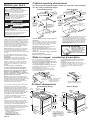
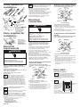
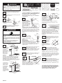
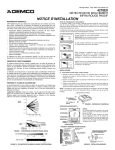
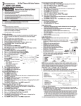
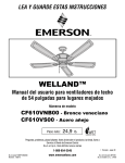
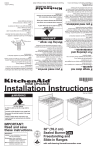
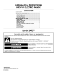
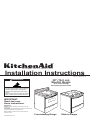
®
HOME APPLIANCES
Installation Instructions
Part No. 9752043 Rev. B
WARNING
30" (76.2 cm)
Electric Range
with self-cleaning
thermal/convection oven
Tip Over Hazard
A child or adult can tip the range and be killed.
Connect anti-tip bracket to rear range foot.
Reconnect the anti-tip bracket, if the range is
moved.
Failure to follow these instructions can result in
death or serious burns to children and adults.
IMPORTANT:
Read and save
these instructions.
IMPORTANT:
Installer: Leave Installation Instructions with the
homeowner.
Homeowner: Keep Installation Instructions and anti-tip
bracket template for future reference.
Save Installation Instructions for local electrical
inspector's use.
www.kitchenaid.com
Freestanding Range
Slide-in Range
Before you start...
Your safety and the safety of others
are very important.
We have provided many important safety
messages in this manual and on your appliance.
Always read and obey all safety messages.
This is the safety alert symbol.
This symbol alerts you to potential hazards
that can kill or hurt you and others.
All safety messages will follow the safety alert
symbol and either the word “DANGER” or
“WARNING”. These words mean:
Cabinet opening dimensions
25" (63.5 cm) countertop depth and 24" (61 cm) base cabinet depth,
36” (91.4 cm) countertop height
Slide-in Range
Freestanding Range
30" (76.2 cm) min.
cabinet opening width
WARNING
junction box –
8" (20.3 cm) to
22" (55.9 cm) from
either cabinet,
7" (17.8 cm) max.
from floor.
You can be killed or seriously injured if you
don’t follow instructions.
All safety messages will tell you what the potential
hazard is, tell you how to reduce the chance of
injury, and tell you what can happen if the
instructions are not followed.
Check location where range will be installed.
The range should be located for convenient use
in the kitchen. Recessed installations must
provide complete enclosure of the sides and rear
of range.
ALL OPENINGS IN THE WALL OR FLOOR
WHERE RANGE IS TO BE INSTALLED MUST
BE SEALED.
IMPORTANT: Some cabinet and building
materials are not designed to withstand the heat
produced by the oven for baking and selfcleaning. Check with your builder or cabinet
supplier to make sure that the materials used
will not discolor, delaminate or sustain other
damage.
It is the customer’s responsibility:
To contact a qualified electrical installer.
To assure that the electrical installation is
adiquate and in conformance with National
Electrical Code, ANSI/NFPA 70 — latest
edition*, or CSA Standard C22.1, Canadian
Electrical Code, Part 1 — latest edition**, and
all local codes and ordinances.
The installation of this range must conform to the
Manufactured Home Construction and Safety
Standards, Title 24 CFR, Part 3280 (formerly the
Federal Standard for Mobile Home Construction
and Safety, Title 24, HUD, Part 280); or when such
standard is not applicable, the Standard for
Manufactured Homes Installations (Manufactured
Home Sites, Communities and Setups), ANSI
A225.1/NFPA 501A, or with local codes*.
7/8" (2.2 cm)
min. required
between cutout
and cabinet
door or hinge.
*** Note: 24" (61 cm) min. when bottom of wood or metal
** Canadian Standard Association
178 Rexdale Boulevard
Rexdale (Toronto), Ontario M9W 1R3
Panel A
Anti-tip bracket:
The floor anti-tip bracket
MUST be installed. To
install the anti-tip bracket
shipped with the range,
see Panel C and the
anti-tip bracket template.
Slide-in ranges: countertop preparation
The cooktop sides of the slide-in range fit over
the cutout edge of your countertop.
If you have a square finish (flat) countertop
and the opening width is 30-3/8" (77.2 cm), no
countertop preparation is required.
Formed front-edged countertops: Must have
molded edge shaved flat 1/4" (0.64 cm) from
each front corner of opening.
Tile countertops may need trim cut back
1/4" (0.64 cm) from each front corner and/or
rounded edge flattened.
30-3/8"
(77.2 cm)
opening
width
If countertop opening width is greater than
30-3/8" (77.2 cm), adjust the 1/4" (0.64 cm)
dimension.
Countertop must be level. Place level on
countertop, first side to side; then front to back. If
countertop is not level, range will not be level.
Oven must be level for satisfactory baking
conditions.
1/4"
(0.64 cm)
30-7/8"
(78.4 cm)
22-5/8"
(57.5 cm)
Formed or tiled countertop
trimmed 1/4" (0.64 cm)
back at front corners of
countertop opening.
Cooktop sides of range fit over
edges of countertop opening.
Product dimensions
Freestanding Range
8-1/4"
(21 cm)
Slide-in Range
30"
(76.2 cm)
cooktop
width
30"
(76.2 cm)
cooktop
width
1-1/2"
(3.8 cm)
44-3/8"
(112.7 cm)
overall
height
When this range is installed in a mobile home, it
must be secured to the floor during transit. Any
method of securing the range is adequate as long
as it conforms to the standards listed above.
Copies of the standards listed may be obtained from:
* National Fire Protection Association
One Batterymarch Park
Quincy, Massachusetts 02269
cabinet is protected by not less than 1/4" (0.64 cm)
flame retardant millboard covered with not less than
No. 28 MSG sheet steel, 0.015" (0.4 mm) stainless steel,
0.024" (0.6 mm) aluminum or 0.020" (0.5 mm) copper.
30" (76.2 cm) min. clearance between the top of the
cooking platform and the bottom of an unprotected
wood or metal cabinet.
Important: Observe all governing codes and
ordinances.
When installing a range under existing cabinets
and the installation does not meet the minimum
cabinet clearances, install a range hood above
the cooktop to avoid burn hazards.
Grounded electrical outlet is required. See
“Electrical requirements,” Panel B.
Cabinet opening dimensions that are shown
must be used. Given dimensions are minimum
clearances.
Do Not pinch the power supply cord between
the range and the wall.
Do Not seal range to side cabinets.
In Canada, the installation of this range must
conform with the current standards
CAN/CSA-Z240 — latest edition**, or with local
codes.
Four-wire power supply cable must be used in a
mobile home installation. The appliance wiring will
need to be revised. See four-wire electrical
connection, Panel B.
junction box – 8" (20.3 cm) to
22" (55.9 cm) from either
cabinet, 7" (17.8 cm) max. from
floor.
7/8" (2.2 cm)
min. required
between cutout
and cabinet
door or hinge.
Note: The metal chassis of the range MUST be
grounded in order for the control panel to work. If
the metal chassis of the range is not grounded, NO
keypads will operate. Check with a qualified
electrician if you are in doubt as to whether the
metal chassis of range is grounded.
Mobile home installation
1/2" (1.3 cm)
radius both
corners
30-3/8" (77.2 cm)
opening width
4" (10.2 cm)
min. clearance
from both sides
of range to side
wall or other
combustible
material.
Read electrical and carpentry instructions.
Proper installation is your responsibility. A
qualified technician must install this range. Make
sure you have everything necessary for correct
installation. It is the customer’s responsibility to
make sure that the countertop has been properly
prepared and that the installation clearances
specified on the model/serial rating plate are
met. The model/serial rating plate is located on
the oven frame behind the drawer.
22-3/4" (57.8 cm)
opening depth
30-1/4" (76.8 cm)
opening width
4" (10.2 cm)
min. clearance
from both sides
of range to side
wall or other
combustible
material.
For minimum
clearance to
the top of the
cooktop, see
Note.***
30" (76.2 cm) min.
cabinet opening width
18" (45.7 cm)
upper cabinet
to countertop
18" (45.7 cm)
upper cabinet
to countertop
DANGER
You can be killed or seriously injured if you
don’t immediately follow instructions.
13" (33 cm) max.
upper cabinet depth
For minimum
clearance to
the top of the
cooktop, see
Note.***
13" (33 cm) max.
upper cabinet depth
36" (91.4 cm)
cooktop
height with
feet loosened
1-1/2 turns
36" (91.4 cm)
cooktop
height with
feet loosened
1-1/2 turns
22-5/8"
(57.5 cm)
1"
(2.5 cm)
1" (2.5 cm)
spacer
27-3/4"
(70.5 cm)
depth with
handle
30"
(76.2 cm)
width
When installed in a 24"
(61 cm) base cabinet with
25" (63.5 cm) countertop —
front of oven door
protrudes 1-7/8" (4.8 cm)
beyond 24" (61 cm) base
cabinet.
25-3/4"
(65.4 cm)
depth with
handle
30"
(76.2 cm)
width
Tools needed for
installation:
level
3/8"
ratchet
Phillips
screwdriver
pliers
flat-blade
screwdriver or
5/16" nut
driver
This range should be connected
directly to the fused disconnect or circuit
breaker box through flexible, armored or
non-metallic sheathed, copper cable (with
ground wire). Locate the junction box to allow
two to three feet of slack in the line so that the
range can be moved if servicing is ever
necessary. Do Not cut the conduit.
D.
hammer
wrench
Electrical
connection
Parts supplied for
installation:
anti-tip
bracket
(Bracket must be
securely mounted to
sub-floor. Thickness
of flooring may
require longer
screws to anchor the
bracket to sub-floor.)
Electrical
requirements
WARNING
Electrical Shock Hazard
Electrically ground range.
Failure to follow these instructions can
result in death, fire, or electrical shock.
If codes permit and a separate ground wire is
used, it is recommended that a qualified
electrician determine that the ground path is
adequate.
Do Not ground to a gas pipe.
Check with a qualified electrician if you are not
sure range is grounded.
When a four-wire or three-wire, singlephase, 120/240-volt, 60-Hz, AC-only,
electrical supply is available, a 50-ampere
maximum circuit protection is required, (or, if
specified on the model/serial rating plate, when a
four-wire or three-wire, single-phase 120/208-volt,
60 Hz, AC-only electrical supply is available, a 40ampere maximum circuit protection is required),
fused on both sides of the line. A time-delay fuse or
circuit breaker is recommended. The model/serial
rating plate is located on the oven frame behind the
drawer.
A.
THE RANGE MUST BE CONNECTED
WITH COPPER WIRE ONLY.
Wire sizes and connections must conform
to the requirements of the National
Electrical Code, ANSI/NFPA 70 — latest
edition* or CSA Standard C22.1, Canadian
Electrical Code, Part 1 — latest edition** and all
local codes and ordinances for the kilowatt rating of
the range.
Copies of the standards listed may be obtained from:
* National Fire Protection Association
One Batterymarch Park
Quincy, Massachusetts 02269
** Canadian Standard Association
178 Rexdale Boulevard
Rexdale (Toronto), Ontario M9W 1R3
Panel B
black
wires
white
wires
cable from
range
U.L.-listed
conduit
connector
Grounded Neutral
WARNING
Electrical Shock Hazard
Turn power supply off before connecting
wires.
Use 8-gauge solid copper wire.
Electrically ground range.
Failure to follow these instructions can
result in death, fire, or electrical shock.
1. Disconnect the power supply.
2. Remove the terminal block cover.
3.Connect together 3 wires: green and white
appliance cable wires and the neutral (white)
wire in junction box.
4. Connect the two black wires together; then the
two red wires together. See Figure 2.
C. Where local codes DO NOT
permit...
connecting the cabinet-grounding conductor
to the neutral (white) junction box wire.
Junction
box
This range must be connected to a grounded,
metallic, permanent wiring system, or a
ground connector should be connected to
the ground terminal or wire lead on the
range.
Connect the range cable to the junction box
through a U.L.-listed conduit connector.
Complete electrical connection according to local
codes and ordinances.
Note: The metal chassis of the range MUST be
grounded in order for the control panel to work. If
the metal chassis of the range is not grounded, NO
keypads will operate. Check with a qualified
electrician if you are in doubt as to whether the
metal chassis of range is grounded.
A. If connecting to a four-wire
electrical system...
Cable from
power supply
White
wires
Red
wires
This range is manufactured with white (neutral)
power supply wire and a cabinet-connected
green ground wire twisted together.
Bare or
green
wires
Figure 3
Black wires
cable from
range
U.L.-listed
conduit
connector
Grounded Neutral
1. Disconnect the power supply.
2. Separate the green and white appliance cable
wires.
3. Connect the white appliance cable wire to the
neutral (white) wire in the junction box.
4. Connect the two black wires together; then the
two red wires together. See Figure 3.
5. Connect the green or bare ground wire from
the appliance cable to a grounded wire in the
junction box.
Do Not connect the cabinet-grounding
conductor to the neutral (white) junction box
wire:
junction
box
cable from
power supply
white
wires
red
wires
Now start...
With range in kitchen.
Do Not have a fuse in the neutral or
ground circuit.
B.
C.
cable from
power supply
red
wires
Figure 2
hand or electric drill
wood floor: 1/8" drill bit
concrete/ceramic floor:
3/16" carbide-tipped
masonry drill bit
2 screws
(#10 x 1-1/2")
junction
box
A U.L.-listed conduit connector must be provided
at each end of the power supply cable (at the
range and at the junction box). Wires sizes
(COPPER WIRE ONLY) and connections must
conform with the rating of the range.
measuring tape
or ruler
2 plastic
anchors
connecting the cabinet-grounding conductor
to the neutral (white) junction box wire:
bare or
green wire
safety
glasses
gloves
B. Where local codes permit...
black
wires
bare or
green
wires
Figure 1
cable from
range
U.L.-listed
conduit
connector
1. Disconnect the power supply.
2. Separate the green (or bare) and white
appliance cable wires.
3. Connect the white appliance cable wire to the
neutral (white) wire in the junction box.
4. Connect the two black wires together; then the
two red wires together. See Figure 1.
5. Connect the green appliance cablewire to the
green ground wire in the junction box.
Put on safety glasses and gloves.
Remove shipping materials, tape and
protective film from range. Keep
cardboard bottom and shipping base under
range. Remove oven racks and parts package
from inside oven.
1.
2.
Take 4 cardboard
cardboard
corners
corners from the
carton. Stack one
cardboard corner
on top of another.
Repeat with the
other two
corners. Place
spacers
corners lengthwise
on the floor in back of range so corners will
support outer side edges of range as shown.
!
NIGHT LIGHT
WARNING
888
Excessive Weight Hazard
Use two or more people to move and install
range.
Failure to follow this instruction can result
in back or other injury.
ON
EASY CONVECT
BAKE
BROIL
• MAXI
• • ECONO
BROIL
SET
START
18:88 TIME
PROBE TEMP
8:88
CLEAN
18:88
CHECK
FOOD AT
CLOSE
DOOR
MEATS
1
2
3 CONTROL
LOCK
4
5
6
COOK
TIME
7
8
9
STOP
TIME
CONVECT
FULL
MEAL
0
CONTROL LOCK
LOCKED START ?
OTHER
FOODS
ROAST
START
18:88
STOP
TIME
EASY CONVECT CONVERSION
BAKED
GOODS
CONVECTION
BAKE
DELAY
O
RAISING
F
BREAD
DEHYDRATE
CONVECTION
ENTER STANDARD COOK TIME
COOK TEMP
CLEAN TIME
MIN SEC
HR MIN
CLOCK
SET • START
CANCEL
OVEN
LIGHT
TIMER
SET•START
OFF
CANCEL
Control panels may vary.
To mount anti-tip
bracket to wood floor,
use the anti-tip bracket
template to mark
where to drill mounting
holes. Use a drill with a
1/8" (0.3 cm) drill bit to
drill the two holes.
Remove template from
floor.
To mount anti-tip bracket to concrete or
ceramic floor, use the anti-tip bracket template
to mark where to drill mounting holes. Use a drill
with a 3/16" (0.48 cm) masonry drill bit to drill the
two holes. Remove template from floor. Tap
plastic anchors into mounting holes in floor with
hammer.
Use an adjustable wrench
to loosen the leveling legs
1-1/2 turns.
6.
Place cardboard or hardboard in front
of range. Stand range back up onto
cardboard or hardboard.
WARNING
Tip Over Hazard
A child or adult can tip the range and be
killed.
Connect anti-tip bracket to rear range foot.
Reconnect the anti-tip bracket, if the range
is moved.
Failure to follow these instructions can
result in death or serious burns to
children and adults.
If countertop is
not flush to the
side of cabinet
opening, align
the left side of
the template to
allow for the
countertop
overhang. Tape
the range anti-tip
bracket template
in place.
A
Countertop
overhangs
cabinet side.
A = Difference
between
countertop
depth and 25"
(63.5 cm).
A
slide-in cutout
shown
Panel C
anti-tip
bracket
template
10.
11.
Remove cardboard or hardboard from
under range. Carefully move range
into final position.
12.
Press on front
of storage
drawer and
release to open.
Pull open to first stop position.
Lift front of drawer to clear white
wheels in drawer guides. Remove drawer and set
it aside on a protected surface.
Push in and
turn each
surface unit
control knob to "HI"
position. Check the
operation of the cooktop
elements and indicator
lights.
OFF
16.
LO
25" (63.5 cm)
Move range close to cabinet opening.
Make electrical connection. See
“Electrical requirements” and
“Electrical connection,” Panel B, for details. “8888”
should appear in the clock display. Refer to Use
and Care Guide for information on electronic
controls.
15.
Insert storage drawer into slide rails
on sides of drawer opening. Lift front
of drawer slightly and push firmly to
close drawer.
D
Place the anti-tip
bracket template
on the floor in
the cabinet
slide-in
opening so that
cutout
shown
the left edge is
against cabinets
and the top
edge is against
anti-tip
the rear wall,
bracket
molding or
template
cabinet. If
countertop opening is deeper than 25 inches
(63.5 cm), measure and mark a distance 25
inches (63.5 cm) in from front of countertop
opening and align template with mark
(or subtract 25 inches (63.5 cm) from countertop
depth and add the difference to the 2-1/4-inch
(5.7 cm) dimension).
Line up holes in anti-tip
bracket with holes in floor.
Use the screws provided
to fasten anti-tip bracket
to floor.
NOTE: Anti-tip
bracket must be
mounted securely to the
sub floor. Depending on the thickness
of your flooring, longer screws may be
necessary to anchor the bracket to the sub floor.
Longer screws are available from your local
hardware store.
Place rack in
oven. Place
level on rack, first side
to side; then front to back. If the range
is not level, pull range forward until the rear
leveling leg is removed from the anti-tip bracket.
Adjust the leveling legs up or down. Then slide
range back into position. Check that leveling leg
is engaged in anti-tip bracket.
NOTE: Oven must be level for satisfactory baking
conditions.
ME
7.
25" (63.5 cm) countertop over
24" (61 cm) cabinet
9.
14.
HI
HI
5.
Look under range
(a flashlight may
be needed) to
check that left rear
leveling leg is
engaged in the anti-tip
bracket. If leveling leg is
not properly engaged,
remove and reposition the anti-tip bracket to
insure that the leveling leg fits properly in the
anti-tip bracket.
ED
8.
13.
M
4.
Pull cardboard bottom and shipping base
firmly to remove.
Contact a qualified floor covering installer for
the best procedure of drilling mounting holes
through your type of floor covering.
Before moving, slide range onto cardboard
or hardboard.
LO
3.
Firmly grasp the range and gently lay it
on its back on the cardboard corners.
MED
Check the operation of the oven
element. Press the “BAKE” pad.
“350°F” will appear in the temperature
display. Press the “START” pad. “Lo” will appear
in the display; then “170°F” (when oven reaches
170°F).
The bottom element should glow red and the
indicator light should be on. The upper element
should become hot but not glow red. As the oven
temperature rises, the temperature in the display
will increase in 5°F increments until the oven
reaches the set temperature.
Press “CANCEL/OFF” pad.
17.
Check the operation of the broil
element. Close the oven door. Press the
“BROIL” pad. “500°F” will appear in the
temperature display. Press the “START” pad.
Look through the oven window. The top element
should glow red. Press the “CANCEL/OFF” pad.
18.
To get the most efficient use from your
new electric range, read your KitchenAid
Use and Care Guide. Keep Installation
Instructions and Guide close to the
electric range for easy reference.
If the range does
not operate...
For cleaning and
maintenance...
If you need
assistance...
• Check that the circuit breaker is not tripped or
the house fuse blown.
• Check that power supply cord is plugged into
wall receptacle.
If removing the range is necessary for cleaning
or maintenance, disconnect the electric supply.
If electrical supply is inaccessible, lift the range
slightly at the front and pull the range away from
the wall. Pull the range out only as far as
necessary to disconnect the electrical supply
line.
Remove the range to complete cleaning or
maintenance.
Move range back into operating position.
Remove drawer. Level the range. Reconnect the
electrical supply. Make sure that left rear leveling
leg is engaged in the anti-tip bracket.
The KitchenAid Consumer Assistance Center will
answer any questions about operating or
maintaining your range not covered in the
Installation Instructions. The KitchenAid
Consumer Assistance Center is open 24 hours a
day, 7 days a week. Just dial 1-800-422-1230 –
the call is free within the continental United
States.
When you call, you will need the range model
number and serial number. Both numbers can be
found on the model/serial rating plate located on
the oven frame behind the door.
NOTE:
Refer to Use and Care Guide for operating
instructions and cleaning instructions.
WARNING
Accessories
Tip Over Hazard
A child or adult can tip the range and be killed.
Connect anti-tip bracket to rear range foot.
Reconnect the anti-tip bracket, if the range is
moved.
Failure to follow these instructions can result in
death or serious burns to children and adults.
Slide-in ranges only:
• Horizontal Backguard
Part No. 9752090PW – White
9752090PT – Almond
9752090PB – Black
If you need
service...
In the event that your KitchenAid appliance
should need service, call the dealer from whom
you purchased the appliance or a KitchenAidauthorized service company. A KitchenAidauthorized service company is listed in the
Yellow Pages of your telephone directory under
“Appliances – Household – Major – Service &
Repair." You can also obtain the service
company’s name and number by dialing, free
within the continental United States, the
KitchenAid Consumer Assistance Center
telephone number, 1-800-422-1230. A special
operator will tell you the name of your nearest
KitchenAid-authorized service company.
Maintain the quality built into your KitchenAid
appliance — call a KitchenAid-authorized service
company.
®
Part No. 9752043 Rev. B
© 2000 KitchenAid
® Registered Trademark of KitchenAid.
HOME APPLIANCES
Prepared by KitchenAid, Benton Harbor, Michigan 49022
Printed in U.S.A.