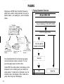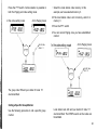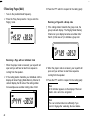
1
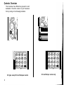
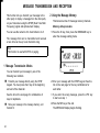
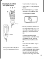
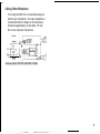
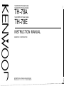
144/430 MHz FM Dual Bander
144/440 MHz FM Dual Bander
TH-78A
TH-78E
144/430MHz FM Dual Bander
INSTRUCTION MANUAL
KENWOOD CORPORATION
@PRINTED IN JAPAN B62-0248-30(W)(MC)
94/654321 93/1211 1098765432
CONTENTS
ACCESSORIES . . . . . . . . . . . . . . . . . . . . . . . . . . 5
BEFORE OPERATION . . . . . . . . . . . . . . . . . . . . 5
Controls Overview . . . . . . . . . . . . . .
.. . . . .
6
.. . . . .
...
.
...
..
...
.
. .
8
8
8
9
9
THE BATTERY PACK
1 NiCd Battery Pack (PB-13). . . . . . . .
2 Recharging. . . . . . . . . . . . . . . . . . . .
3 Installing The Battery Pack. . . . . . .
4 Battery Voltage Level . . . . . . . . . . .
5 Battery Operating Time . . . . . . . . .
RECEIVER OPERATION
1
2
3
4
5
6
Getting started. . . . . . . . . . . . . . . . .
Tuning Control and Volume Control
Selecting Frequency . . . . . . . . . . . .
Step Size Selection . . . . . . . . . . . . .
Programmable VFO Tuning Limits .
Basic Receiving Functions . . . . . . .
.
..
..
..
..
. . . 10
. . . 10
. .12
. . .14
. . 15
. . .16
7 Entering The Call Channel Frequency. . . . . 21
8 Recalling Memory Channels . . . . . . . . . . . . . 22
9 Memory Shift . . . . . . . . . . . . . . . . . . . . . . . . . .22
10 Memory Channel Character Display. . . . . . . . 23
SCANNING
2
3
4
5
6
7
8
9
10
11
13
I
TRANSMITTER OPERATION
1
2
3
4
To transmit . . . . . . . . . . . . . . . . . . . . . . . . . . .I7
Changing Transmitter Output Power . . . . . .17
TX. Stop Function . . . . . . . . . . . . . . . . . . . . .18
Time Out Timer . . . . . . . . . . . . . . . . . . . . . . .18
USING THE MEMORY
1
2
3
4
5
6
Microprocessor Memory Backup . . . . . .
Initializing The Memory . . . . . . . . . . . . . .
Memory Channel . . . . . . . . . . . . . . . . . . .
Memory Contents. . . . . . . . . . . . . . . . . . .
Entering Memory Data. . . . . . . . . . . . . . .
Entering Split Channel Frequencies. . . .
. . .19
. . .19
. . .19
. . .20
. . .20
. . 21
L
Hold/Resume Programming . . . . . . . . . . . . . . 24
Scan operation cancel. . . . . . . . . . . . . . . . . . .24
Scan Options . . . . . . . . . . . . . . . . . . . . . . . . . .25
Scanning Memory Channels. . . . . . . . . . . . . .25
Scanning Band . . . . . . . . . . . . . . . . . . . . . .... 6
Programmable Band Scan. . . . . . . . . . . . . . . .26
MHz Scan . . . . . . . . . . . . . . . . . . . . . . . . . . . . . 2 7
VFO/Memory Scan . . . . . . . . . . . . . . . . . . . . . 27
CALL/VFO Scan . . . . . . . . . . . . . . . . . . . . . . . 28
CALL/Memory Scan . . . . . . . . . . . . . . . . . . . . 2 8
V/M/C(VFO/Memory/CALL) Scan. . . . . . . . . 28
The Alert Function . . . . . . . . . . . . . . . . . . . . . .28
REPEATER OPERATION
1
2
3
4
5
6
7
8
Transmitter Offsets . . . . . . . . . . . . . . . . . . . .
Selecting the Offset Direction. . . . . . . . . . . .
Automatic Offset Selection. . . . . . . . . . . . . .
Manual Offset Selection . . . . . . . . . . . . . . . .
The Reverse Function . . . . . . . . . . . . . . . . . .
Tone Operation. . . . . . . . . . . . . . . . . . . . . . . .
Autopatch Operations . . . . . . . . . . . . . . . . . .
DTMF Memory . . . . . . . . . . . . . . . . . . . . . . . .
.29
.29
.29
.30
.30
.31
.32
.33
OPERATION AS A REPEATER . . . . . . . . . . . . . . .34
CTCSS OPERATION . . . . . . . . . . . . . . . . . . . . . . . . .35
THE DUAL TONE SQUELCH SYSTEM (DTSS)
1 DTSS Code. . . . . . . . . . . . . . . . . . . . . . . . . . . . 36
2 Using the DTSS Function . . . . . . . . . . . . . . . . 36
3 Using DTSS with a Repeater. . . . . . . . . . . . . . 37
PAGING
1
2
3
4
5
6
7
8
Paging Operation Overview . . . . . . . . . . . . . . 38
Paging Code Memory . . . . . . . . . . . . . . . . . . . 39
Setting Paging Codes . . . . . . . . . . . . . . . . . . .39
Sending Pages (Calling). . . . . . . . . . . . . . . . . .40
Receiving Pages Wait) . . . . . . . . . . . . . . . . . .42
Canceling Signal Squelch. . . . . . . . . . . . . . . . .43
Locking Out Codes . . . . . . . . . . . . . . . . . . . . . 4 3
Answer-Back . . . . . . . . . . . . . . . . . . . . . . . . . .43
MESSAGE TRANSMISSION AND RECEPTION
1
2
3
4
5
6
Message Transmission modes. . . . . . . . . . . .
Using the Message Memory. . . . . . . . . . . . . .
Message Memory Check . . . . . . . . . . . . . . . .
Message Memory Transmission. . . . . . . . . . .
Message Reception . . . . . . . . . . . . . . . . . . . .
Receive Message Memory. . . . . . . . . . . . . . .
44
44
46
46
46
47
ENHANCED RECEIVER FUNCTIONS
1 The Tone Alert System . . . . . . . . . . . . . . . . . .48
2 Monitor . . . . . . . . . . . . . . . . . . . . . . . . . . . . . . .49
3 BeepOff . . . . . . . . . . . . . . . . . . . . . . . . . . . . . . 49
4 Lamp . . . . . . . . . . . . . . . . . . . . . . . . . . . . . . . . 4 9
5 Key Lock . . . . . . . . . . . . . . . . . . . . . . . . . . . . . 4 9
6 Volume adjustment when you use
anearphone . . . . . . . . . . . . . . . . . . . . . . . . . . . 50
7 Switching speaker output when a speakermicrophone is connected. . . . . . . . . . . . . . . . 50
8 Automatic Band Change Function . . . . . . . . . 51
4
9 Simultaneous Receive Function of Two
Signal in the Same Band . . . . . . . . . . . . . .51
10 Single Band Operation. . . . . . . . . . . . . . . . . . .52
11 MHz Mode . . . . . . . . . . . . . . . . . . . . . . . . . . . .52
12 Channelized Frequency Display. . . . . . . . .52
POWER SAVER FEATURES
1 The Battery Saver Mode , . . . . . . . . . . . . . . . .53
2 Automatic Power Off (APO). . . . . . . . . . . . . . 53
CLOCK FUNCTION
1 Time Setting . . . . . . . . . . . . . . . . . . . . . . . . .54
2 Timer Function . . . . . . . . . . . . . . . . . . . . . . . .54
DUPLEX OPERATION . . . . . . . . . . . . . . . . . . . . . .56
POWER ON MESSAGE AND FUNCTION
MESSAGE
1 Power On Message . . . . . . . . . . . . . . . . . . . . .57
2 Function Message . . . . . . . . . . . . . . . . . . . . . .57
MAINTENANCE
1 General Information . . . . . . . . . . . . . . . . . . . . .59
2 Service . . , , . . . . . . . . . . . . . . . . . . . . . . . . . . .59
3 Record Keeping . . . . . . . . . . . . . . . . . . . . . . . .59
TROUBLESHOOTING . . . . . . . . . . . . . . . . . . . . . . 60
ACCESSORIES . . . . . . . . . . . . . . . . . . . . . . . . . . . 61
1 Installing the CTCSS Unit (TSU-7). . . . . . . . .
2 Memory Expansion Unit (ME-l). . . . . . . . . . .
3 Programming the SMC-33 Remote Control
SpeakerMicrophone . . . . . . . . . . . . . . . . . .
4 Using other microphone . . . . . . . . . . . . . . . .
63
64
65
67
SPEClFlCATlONS . . . . . . . . . . . . . . . . . . . . . . . . . 6 8
QUICK REFERENCE . . . . . . . . . . . . . . . . . . . . . . 69
ACCESSORIES
Antenna . . . . . . . . . . . . . . . . . . . . . . .
Belt Hook . . . . . . . . . . . . . . . . . . . . . .
Hand Strap . . . . . . . . . . . . . , . . . . . .
Rubber Cap . . . . . . . . . . . . . . . . . . . .
AC plug (M type only) . . . . . . . . . . . . .
Battery Case (TH-78Q type only) . . .
NiCd Battery Pack(PB-13) . . . . . . . . .
Battery Charger(BC-14)
BEFORE OPERATION
T90-0444-X X
J29-0465-X X
J69-0312- X X
B09-0330- X X
E19-0254- X X
A02-1658-X X
W09-0563-X X
for U.S.A. and Canada (12OV)
W09-0565- X X
W09-0569- X X
. . . . . . . . . . . . . . . . . . . . . . . W09-0568- X X
for Oceania (240V)
W09-0567- X X
for other market (120/240V)
. . . . . . . . . . . . . . . . . . . . . . . W09-0566- X X
Instruction Manual . . . . . . . . . . . . . . . B62-0248-X X
Warranty Card(U.S.A.,Canada,and Europe)
Note
Your transceiver comes with a portable dual-band
flex antenna. For fixed transceiver locations, we
recommend that you use a more permanent
antenna installation to help eliminate interference
and improve performance.
Thank you for purchasing this KENWOOD
transceiver. To get the most out of its many features,
we suggest you read this instruction manual
carefully, and keep it handy for further reference.
1
To get ready to transmit and receive.
Check the accessories list to be sure everything you
need has been included in the package.
2 Charge the included NiCd battery pack, following the
instructions completely before proceeding. (See page 8)
When you have everything checked out and charged,
you’re ready to get to the Receiver Operation section
and get up and running with your new equipment.
Other sections follow in a logical order to help you
learn and use this transceiver to its full potential.
CAUT/ON
The recommended transceiver duty cycle is 1
minute of transmission and 3 minutes of reception.
Longer transmissions or extended operation in the
HI power mode may cause the back of the
transceiver to get warm. Do not place the
transceiver where the heat sink (rear panel) might
come in contact with plastic or vinyl surfaces.
Controls Overview
This transceiver has different key layouts for each
destination. Check the version of your transceiver
first by looking at the following illustration.
All types except U.K and European version
6
U.K and Europe version only
This diagram will help you locate the keys, switches,
and knobs you’ll need to perform necessary
operations. Please study these controls carefully. By ANTTENA
CONNECT
the time you reach the end of this manual, you will
have had to use each of them many times.
BUSY (GREEN)/ON AIR (RED)
INDICATOR FOR VHF BAND
DC IN TERMINAL
SPEAKER/HEADPHONE JACK
MICROPHONE JACK
BUSY (GREEN)/ON AIR (RED)
INDICATOR FOR UHF BAND
TUNING CONTROL/VOLUME CONTROL
FOR VHF BAND
SQUELCH CONTROL FOR UHF BAND
SQUELCH CONTROL
FOR UHF BAND
key
-PTT
key
key
DISPLAY PANEL
key
key
MICROPHONE
CONTROL PANEL
All types except U.K and European version
U.K and Europe version only
7
RECEIVER OPERATION
2 Tuning Control and Volume Control
1 Getting Started
Connect the battery pack and the supplied antenna.
Press the POWER switch to turn the transceiver on.
One of the default frequencies should appear on the
display.
This transceiver assigns two volume and tuning
control functions to the two controls.
Before proceeding to the next step, master these
functions. The default setting is as follows:
Functions as the
volume control for
the UHF band.
dissappear
-after 2
seconds
If the display shows incomplete data, or you think the
displayed frequency is wrong, reset the microprocessor Memory Initialization (see page 19)
10
Functions as the
tuning control for
the UHF band.
When you press the BAND key, control of each
function is transferred to the VHF band.
When you press and hold the E.CHG key (or within
two seconds of pressing the E.CHG key), each
control temporary control of the volume or tuning
control passes to the VHF band.
We recommend that you use this function in order to
temporarily change the volume or frequency of the
normally uncontrolled band.
Separate tuning control function
While operating the separate volume control mode,
press the F key then the E.CHG key.
Separate volume control function
Press the F key then press the E.CHG key.
Functions as the
volume control for
the VHF band.
\
Functions as the
volume control for
the UHF band.
Functions as the
tuning control for
the VHF band.
Functions as the
tuning control for
the UHF band.
\
Returning to the original mode.
Press the F key for longer than one second then
press the E.CHG key.
11
Whenever you are selecting frequencies, your first
step should be to set the squelch control. The
squelch helps eliminate “white noise” or static until
you receive active communications on a frequency.
There are two squelch controls, one for the UHF
band and one for the VHF band. To set the squelch
controls:
VHF BAND
UHF BAND
3 Selecting a Frequency
You have several ways to select frequencies:
*
By entering a specific frequency via the keyboard
n
By using the tuning control
n
By selecting a memory channel (see page 22)
n
By pressing the CALL key
Direct Keyboard Frequency Entry
You can enter specific frequencies directly into the
transceiver. If you don’t have a particular freqency
to enter, we suggest you try 145.050MHz.
1 Press the BAND key to change the primary band
from UHF band to VHF band.
2 If the transceiver is in the Memory mode or CALL
mode, press the VFO key to select the VFO mode.
1
Rotate the VOL control clockwise until a signal or
noise is heard coming from the speaker.
2 Rotate the tuning control to selected an open
channel.
3 Press the numeric 4 key. A 4 is entered as the
10MHz digit, and the 1MHz and below digits change
to -.
3 Rotate the SQL control clockwise until the noise just
disappears and the BUSY indicator turns off. This
point is known as the Squelch Threshold point.
4 Press the BAND key.
5 Repeat steps 1 to 3, and adjust the squelch of the
other band.
12
4 Press numeric keys 5,0,5,and 0.
For the European version and some other markets,
Notes
1 If the frequency step of the UHF band is 10 or
20 kHz, the 1 kHz digit becomes zero
automatically when you enter the 10kHz digit.
2 If you press an invalid key, the valid value
nearest to that number is entered.
3 If you do not press a key within 10 seconds, the
normal frequency display returns.
4 If you press the VFO key during input, the digits
showing - return to the values that appeared
before the direct entry mode was selected.
Next press numeric keys 0 and 5.
5 The transceiver actually changes frequency only
after the 1 kHz digit is entered. The 1 kHz digit is
not displayed if it is a zero.
If you do not enter the 1 kHz digit, the indicator
flashes and the transceiver defaults to the previous
operating frequency.
If the frequency step is 12.5 or 25 kHz, the input
ends with the 10-kHz digit. The 10-kHz keys and
frequencies set with the keys are listed below.
Key
Frequency
Key
0
00
1
2
3
4
12.5
25
37.5
37.5
5
6
7
8
9
Frequency
50
62.5
75
87.5
87.5
Using the Tuning Control
The tuning control selects frequencies in up or down
sequentially.
Rotate the tuning control clockwise or
counterclockwise to select the desired operating
frequency.
4 Step Size Selection
The transceiver must be in the VFO mode to select
frequency steps.
To select the desired tuning or scan step size use
the following procedure:
1
Press the F key for longer than one second then
press the 3 key. The current frequency step size will
be displayed.
3 Press the any key except POWER, LAMP and MONI
key.
The displayed step size is set, and the normal
frequency display returns.
Changes in the Displayed Frequency
As you change from one step size to another, the
displayed frequency also changes, as illustrated in
the accompanying charts.
For example, assume you are presently displaying
439.920 MHz at a 20kHz step size. If you were to
change the step size to 12.5kHz, the display would
read 439.925 MHz.
From step size 5, 10, 15, or 20
Frequencies
0,5,10,15
2 Rotate the Tuning control until the desired tuning
step size appears in the display. The frequency step
is indicated in the chart below.
14
To step size 12.5 or 25
Display as
0
20,25,30,35
25
40,45,50,55
50
60, 65, 70, 75, 80, 85, 90, 95
75
5 Programmable VFO Tuning Limits
From step size 12.5 or 25
Frequencies
0
To step size 5,10, 15, or 20
This radio provides the capability of programming the
VFO tuning range, in 1 MHz band segments, as well
as providing a separate programmable band scan
function. (See page 26)
Display as
0
12.5
10
25
20
37.5
30
50
50
62.5
60
75
70
87.5
80
For example you could tell the transceiver that you
only wish to tune the 144.000 MHz and 145.000 MHz
band segment by specifying any frequency within
these two segments.
The Tuning controls would then only tune within
these specific bands. The procedure for specifying
the bands is described below.
1
Select the desired lower tuning limit.
For example you might want to select the 144 MHz
band and dial up 144.100 MHz.
2 Press and hold the M key for longer than one
second, then press the 1 key. This selects the lower
frequency limit for the programmable VFO.
3 Select the desired upper tuning limit.
For example you might want to select the 145 MHz
band and dial up 145.100 MHz.
4 Press and hold the M key for longer than one
second, then press the 2 key. This selects the
upper frequency limit for the programmable VFO.
5 To confirm that the programming was properly
performed rotate the Tuning control. The transceiver
should not go above or below the programmed band
limits.
6 Basic Receiving Functions
When receiving a signal, the Main/Sub S-meter
deflects and the Main/Sub BUSY indicators appea
Rotate the volume control to the desired level.
VFO tuning range
144.000
I
I
145.000
I
146.000
I
147.000
I
To clear the programmed limits simultaneously reset
the VFO memory using the procedures discussed on
page 19.
You can reprogram either limit independently by
following the appropriate instructions above.
16
Note
For information about more advanced receiving
capabilities, see Enhanced Receiver Function on
page 48
TRANSMITTER OPERATION
WARNING:
Before you attempt to transmit, attach an antenna
with a low standing wave ratio to the antenna
connector. Failure to provide a proper load may
cause damage to the final amplifier section. Always
check that the frequency is clear before transmitting.
1 To transmit, follow these steps:
1
Use any of the frequency selection methods
discussed on page 12 to select an operating
frequency.
2 Listen to the frequency to see if it’s occupied before
attempting to transmit on it.
3 Press the PTT (Press to talk) switch. The ON AIR
indicator and battery level meter will appear.
4 Speak into the microphone from the recommended
distance of 5 cm (2 inches). Talking closer or farther
away can result in loss of clarity, an excessively wide
transmit signal, or weak audio.
2 Changing Transmitter Output Power
Press the F key, then the D/LOW key to select three
different transmitter output power levels. Repeat this
function to stop through the power level selections.
The actial transmitter output power for this unit
depends on the power supply used. Indicators will
appear on the display to tell you which level you
have selected.
You can select the transmitter output for both the
VHF and the UHF band.
The “E and L” indicators show the Economic Low
power position. Use Economic Low power for lineof-sight short-distance communication.
The “L” indicators shows the Low power position.
Use Low power for short-distance communication.
5 Release the PTT switch to return to the receive
mode. The ON AIR and battery level meter
indicators should go out.
17
No indicator means the high power position has been
selected. Use high power for maximum transmitter
power.
See the high power CAUTION on page 5.
3 TX. Stop Function
The TX Stop function allows you to temporally
disable the transceiver transmit, preventing
accidental or unauthorized transmission.
Press the F key, then press the f2/TX.S key to turn
the TX. Stop function on or off.
Output Power(watts)
(Apprrox.)
144MHz
PB-13,18
Alkaline Battery
H
L
2.0
0.5
5.0
430/440MHz
L
EL
0.02 2.0
0.5
0.01
0.5
0.02 5.0
0.5
0.01
2.0
0.5
0.02 2.0
0.5
0.01
5.0
0.5
0.02
5.0
I
0.5
0.01
EL
H
TX.S
4 Time-Out-Timer
This transceiver has a time-out-timer function to
prevent possible problems caused by continuous
transmission. This function forcibly stops continuous
transmission after 10 minutes. When the timer times
out, the transceiver beeps and automatically returns
to the RX mode. Press the PTT switch to transmit
again.
The time-out-timer function cannot be turned on or
off.
18
USING THE MEMORY
1 Microprocessor Memory Backup
All memory channel data is backed up in EEPROM.
It is not lost unless you reset the memory.
All other data that you set is retained by a secondary
lithium battery that will provide memory backup for
about 20 days if you remove the battery pack or
external DC power.
A fully discharged battery will require approximately
10 hours to reach full charge after installing a NiCd
battery pack or external power.
2 Initializing The Memory
Press and hold the M key and turn on the power to
reset the memory. All the LCD indicators will appear
on the display. Release the M key. This resets all
user programmed data to the factory defaults.
Factory Default Settings
440/430 MHz Band
144 MHz Band
VFO Frequency
144 MHz
Call Channel
Frequency
144 MHz
Frequency Step
5 kHz/12.5kHz
25 kHz
Tone Frequency
88.5 Hz/1750
88.5
Hz
Hz/1 750 Hz I
VFO Reset
Press and hold the F key and turn on the POWER
switch to reset the microprocessor’s VFO memory,
without destroying the memory channel, CLOCK
data, message memory data, automatic dialer DTMF
memory, Programmable SCAN tuning range,
PAGING code, or CALL channel data.
3 Memory Channel
This transceiver provides 50 memory channels.
In addition to serving as a normal memory channel
Memory Channel 1 is used to store the frequency for
the Priority Alert function.
19
4 Memory Contents
2 Press the M key. The memory indicator will flash.
Each memory channel can store information as
shown in the chart below.
X =Can be stored in memory
Normal
Channel
RX frequency
TX frequency
Tone(CTCSS) frequency,
Tone (CTCSS) status
Frequency step
Shift status, REV on/off
DTSS code. DTSS status
X
X
Split
Channel
N/A
X
3 Use the keypad to select any desired memory
channel number (O-49). Use a two-digit number,
such as 02 for channel 2 or 15 for channel 15, to
enter the data in memory.
4 Press the MR key.
5 Entering Memory Data
Entering memory data is a simple operation requiring
just a few keystrokes to store all the data you
require.
5 The memory channel number will turn off, indicating
that the receiver data has been properly stored.
Clearing a Memory Channel
Entering Normal Simplex/Repeater
Channels
1
Select the desired receive frequency, offset, and any
other information you desire. If the desired
frequency is already on the display, continue to step
2.
Use the following procedure to clear the contents of
an individual memory channel:
1
Select the memory channel to be cleared.
2 Press the M key for longer than one second, then
press the MR key.
3 The selected memory channel number is removed
from the display and the data is cleared from the
memory.
6 Entering Split Channel Frequencies
Use the numeric keypad to select the desired
receiver frequency, tone and other information. If the
desired frequency is already on the display, continue
to step 2.
1
Press the MR key. The programmed receiver
frequency appears on the display with “+” and
“-‘‘ offset direction indicators showing that this
channel has an odd split entered.
Press the M key. The memory indicator will flash.
Use the keypad to select any desired memory
channel number (O-49). For example, use a two
digit number, such as 02 for channel 2, or 15 for
cannel 15, to enter data in memory.
Press the MR key.
The memory channel number will turn off, indicating
that the receiver data has been properly stored.
Use the numeric keys to enter the desired transmit
frequency.
Press the M key. The memory channel indicator will
flash.
Press and hold the PTT switch and then press the
MR key.
The TX frequency is set. The system returns to its
previous state.
Note
You will hear an error sound if you attempt to recall
a memory when nothing is stored in that memory.
2 Press the F key, then press the SHIFT/REV key, or
just the PTT switch, to check the transmit frequency.
The transmit frequency will appear on the display.
7 Entering The Call Channel Frequency
1
Use the numeric keypad to select the desired
receiver frequency, tone and other information.
2 Press the M key, then press the CALL key within 10
seconds. You have now entered the call channel
frequency.
If entering an odd split channel, continue with steps 3
to 6.
21
If you install the optional ME-l, you cannot recall
more than 100 memory channels in the two digits
recall mode (initial states).
3 Select the desired call channel transmit frequency.
4 Press the M key.
5 Press and hold the PTT switch and press the CALL
key.
6 Release the PTT switch.
8 Recalling Memory Channels
Press the MR key.
You can change the memory channel by the
following two methods.
Using the Tuning Control
Rotate the tuning control clockwise or
counterclockwise to select the desired Memory
Channel.
Using the numeric keypad
Select any desired memory channel number (O-49).
For example, use a two digit number, such as 02 for
channel 2, or 15 for cannel 15.
22
You must change the function to three digit recall
mode.
1
Press and hold the MR key and turn the power on.
The VHF band frequency display changes to the
recall selection mode with the numeric keys.
2 Select -3 with the right encoder.
3 Press any front panel key to return to the normal
frequency display.
9 Memory Shift
Press the F key, then press the VFO key to copy the
contents of a memory or call channel to the VFO
without changing the data in memory. Doing this
allows you to begin tuning at the point specified by
the memory channel data.
You cannot perform memory shift if the displayed
frequency exceeds the programmable VFO setting
10 Memory Channel Character Display
You can display the memory channel frequency with
your own spelling. It may be up to six characters
long. You can use numerics 0 to 9 and the letters A
to z.
Function Setting
Press and hold the f² key, and turn the power on.
Note
When you select this function, the memory channel
can be displayed alphanumerically, but the total
number of available memory channels is halved, i.
e., 25.
To return to 50 channels, repeat the operation.
Character registration
1
Press the MR key to enter the memory channel
mode.
2 Select a desired channel from among the memory
channels in which you stored data using the Tuning
control or numeric keypad.
_
3 Press the M key, then press the f² key to enter the
message setting mode.
4 Enter your message with the keypad. See the list on
page 45 for the key combinations for each letter.
5 If you enter the wrong message, press the VFO key
to start over step 4.
6 Press the MR key at the end.
7 You can display a message from other memory
channel by performing steps 2 to 6 again.
Note
A message can be displayed for a maximum of 25
memory channels.
If a message is specified for a memory channel, the
message is displayed instead of the memory channel
number.
If you want to display the memory channel number,
press and hold the F key for longer than one second,
then press the f² key.
Message Display Cancel
1 Select the memory channel to be canceled.
2 Press and hold the M key for longer than one
second, then press the f² key.
The message display is canceled, and the memory
channel is displayed.
23
SCANNING
You must adjust the squelch to the threshold point
for proper scan operation. You cannot use scan in
conjunction with the tone alert function and paging.
Scanning occurs separately in the VHF and UHF
bands.
You can reverse the direction by turning the Tuning
control or MESSAGE key.
In DTSS operation, scan will stop (without squelch
turned off) whenever it receives a sÀðnal. However,
squelch will not open until the proper DTSS signal is
reseived.
In combined CTCSS and DTSS modes, scanning
stops when the proper CTCSS tone is reseived.
Squelch will open only if the DTSS sgnal matches
when the scan stops.
1 Hold/Resume Programming
This transceiver provides two types of scan hold/
resume:
* Time Operated Scan
The transceiver stops scanning on a busy channel,
remains there for approximately 5 seconds, and then
continues to scan even if the signal is still present.
* Carrier Operated Scan
The transceiver stops scanning on a busy channel
and remains there until the signal drops out. It
allows a 2 second delay before resuming scanning to
prevent losing the station when operators change.
In CTCSS operation, scan will stop only on signals
that contain the proper CTCSS code.
Hold/Resume Selection
The transceiver is delivered from the factory in the
Time Operated Scan mode. Use the following
procedure to switch between modes:
n VHF Band :
Press and hold the 8 key and turn on the power.
* UHF Band:
Press and hold the 9 key and turn on the power.
2 Scan operation cancel
Operation band :
Press any key except MONI, LAMP, BAND, MHz,
E.CHG, or MSG.
Sub-band:
Press the BAND key, then press the PTT switch.
24
3 Scan Options
n CALL / Memory Scan
Provides alternate scanning of the call channel and
last used memory channel. (page 28)
The following scan options are available:
* Memory Scan
Scans through those memory channels that have
data stored and that have not been locked out. This
function operates only in the memory mode.
n
V/M/C(VFO/Memory/CALL) Scan
Scans the VFO, the last memory channel used, and
the call channel. (page 28)
* Band Scan
Scan proceeds over the entire band. This function
operates only in the VFO mode. (page 26)
4 Scanning Memory Channels
n Programmable Band Scan
The transceiver scans only those memory channels
that have data entered and are not locked out.
Scanning does not start unless two channels or
more have data entered.
The scan range for this mode is specified in memory.
(page 26)
n MHz Scan
Scans over a 1 MHz range. (page 27)
n VFO / Memory Scan
Provides alternate scanning of the VFO and last used
memory channel. (page 27)
1
Adjust the SQL control to the threshold point.
2 Press the MR key.
3 Press and hold the MR key for longer than one
second. The MHz indicator (decimal) flashes when
the transceiver is scanning.
n CALL/VFO Scan
Locking Out Memory Channels
This function allows you to specify which memory
channels you want to skip during memory channel
scan.
Provides alternate scanning of the call channel and
the VFO. (page 28)
1
Select the appropriate numbers of the memory
channels that you want to skip.
25
2 Press the F key, then the 0/L.OUT key.
A * indicator appears below the memory channel
number on the display, indicating that channel will be
skipped in the memory channel scan mode.
Scanning begins toward the higher frequencies. The
MHz indicator (decimal) flashes when the transceiver
is scanning.
5 Scanning pauses on a station strong enough to open
the squelch and turn the BUSY indicator on.
6 Programmable Band Scan
This transceiver can select and scan a frequency
range in a band.
3 Repeat steps 1 and 2 to lockout any other channels
you may want to skip.
You can set separate limits for both VHF and UHF,
limiting dual scan on both bands.
4 To cancel the lockout, select the memory channel
number. If it was locked out, it will have the *
indicator on the display.
Press the F key and then the 0/L.OUT key. The *
will disappear.
Even if you sets the programmable band scan limits,
the VFO tuning range is not limited unlike the
programmable VFO function. (See page 15.)
For example, you can program so that the
transceiver scans a range from 144.50 to 145.80 in
the VHF band.
Use the following procedure to specify the desired
scan limit.
5 Band scan
1 Adjust the SQL control to the threshold point.
1
2 Press the Band key to select the desired Scanning
Band.
2 Select the desired upper scan limit.
3 Press the VFO key to select the VFO mode.
3 Press and hold the M key for longer than one
second, then press the 5 key.
4 Press and hold the VFO key for longer than one
second.
4 Select the desired lower scan limit.
26
Press the BAND key to select the desired Band.
t
5 Press and hold the M key for longer than one
second, then press the 4 key.
Notes
1 Initialize the VFO memory (VFO RESET) to clear
both programmed limits simultaneously. Press
and hold the F key and turn on the power. You
can reprogram either limit independently.
2 Programmable band scan is not initiated when
the lower frequency limit is not in the same band
or step size, or when it is higher than the upper
limit frequency.
Initiating Programmable Band Scan
1 Adjust the SQL control to the threshold point.
2 Select a frequency between the two programmed
scan limits.
3 Press and hold the VFO key for longer than one
second.
The MHz indicator will flash when the transceiver is
scanning.
7 MHz Scan
1 Adjust the SQL control to the threshold point.
Confirming Scan Limit
* Press the F key for longer than one second, then
press the 4 key to display the band scan lower
frequency limit.
n
2 Start the band scan or programmable band scan.
3 Press the MHz key during band scan or
programmable band scan. Scanning begins in an
upward sequence over a 1 MHz range.
Example: If the MHz key is pressed when the
frequency is 145.02 MHz for VHF band scan, just the
145 MHz band is scanned.
Press the F key for longer than one second, then
press the 5 key to display the band scan upper
frequency limit.
8 VFO/Memory Scan
This function lets you alternately scan the VFO
frequency shown on the display and the last-used
memory channel.
1
Adjust the SQL control to the threshold point.
27
2 Press the F key, then press the MR key.
12 The Alert Function
This function allows you to monitor memory channel
1 for activity once every 5 seconds, even when you
are tuned to a different frequency.
3 The VFO frequency and the last used memory
channel are scanned alternately.
9 CALL/VFO Scan
1
Press and hold the CALL key for longer than one
second in VFO mode.
2 The frequency and CALL frequency are scanned
alternately.
10 CALL / Memory Scan
1
Press and hold the CALL key for longer than one
second in memory channel mode.
2 The memory channel in use and CALL frequency are
scanned alternately.
1
2 Adjust the SQL control to the threshold point.
3 Press the F key, then press the 4 key. The AL
indicator displays.
4 A beep will sound when a signal is present.
5 Press the F key and the 4 key again to turn this
function off. The AL indicator will disappear from the
display.
11 V/M/C(VFO/Memory/CALL) Scan
(except Europian version)
1
Press the F key, then press the CALL key.
When using the Alert function, be aware that:
* Channel 1 CTCSS programming is ignored.
n
You will not hear voice communication while
scanning memory channel 1, only a beep if a signal
is present.
n
Memory channel 1 is also monitored when the dual
band and single band are displayed.
2 The VFO frequency, last used memory channel, and
CALL frequency are scanned alternately.
28
Enter the frequency you wish to monitor in memory
channel 1.
REPEATER OPERATION
1 Transmitter Offsets
3 Automatic Offset Selection
All amateur radio repeaters use a separate receive
and transmit frequency. The receive frequency may
be above or below the transmit frequency. Most
repeater configurations fall into one of the following
categories.
Offset
Direction
UHF Band
VHF Band UHF Band
(European version
n U.S.A. and CANADA versions
The TH-78A is programmed according to the
standard ARRL(Amateur Radio Relay League) Band
Plan for repeater offset direction. You can override
this programming by using the SHIFT key as
described in the preceding paragraph.
n European version
only)
The TH-78E automatic offset is programmed as
follows.
144.00
145.600
SIMPLEX
145.800
- 600 k H z
SIMPLEX
2 Selecting the Offset Direction
Press the SHIFT key. The transceiver will shift from
one offset direction to the other, such as from + to
-, or from - to simplex where no indicator shows.
In the European version (UHF band ), - change
to--.
n
To cancel automatic offset
Press and hold the BAND key and switch the power
on.
This operation switches automatic offset mode on or
off.
29
4 Manual Offset Selection
1
5 The Reverse Function
The factory default sets the automatic offset
frequency. You can select any offset frequency in
the range 0 to 99.9 MHz in 100 kHz steps.
Some repeaters use a ’ reverse pair’, that is, the
transmit/receive frequencies are the reverse of other
repeaters.
Press and hold the SHIFT/REV key and switch the
power on.
For example, repeater A uses 146.000 as an input
frequency, and 146.600 as an output frequency.
Repeater B might use 146.600 as an input
frequency, and 146.000 as an output frequency. It
would be quite inconvenient to have to reprogram the
transceiver each time you want to use these
repeaters.
2 Press the F key for longer than one second, then
press the SHIFT/REV key.
The current offset frequency is shown on the LCD.
3 Rotate the Tuning control, and select the desired
offset frequency.
4 Press any front panel key to return to the normal
frequency display.
Press the F key, then press the SHIFT/REV key.
The R indicator displays to remind you that you are
working a reverse pair.
To return to the normal offset, reset the VFO.
(see page 19)
Note
Selecting an offset frequency that would result in
the radio transmitting outside its intended range
will cause an error tone to be sounded and
transmit to be inhibited. Reselect a valid offset
frequency if this occurs.
Press the F key, then press the SHIFT/REV key
again to return to normal. The R indicator will
disappear.
This function is also useful in checking the repeater
input frequency, allowing you to determine if you are
in range for simplex communication.
30
6 Tone Operation
Some repeaters require a control signal to activate
them. Several different methods are currently in
use.
2 Rotate the tuning control to select the desired tone
frequency(Hz)
In the United States, sub-audible tones are
sometimes used. This transceiver will generate subaudible frequencies.
In Europe and the United Kingdom, a 1750 Hz tone
is used in transmitting. Simply press and hold the
TONE key to transmit the access code. You need
not press the PTT switch. A 1750 Hz tone encoder
is included with models delivered to Europe and the
United Kingdom.
3 Press any key or simply wait 10 seconds for the
transceiver to resume the previous mode.
Tone Function Operating
Selecting Tone Frequencies
If the optional CTCSS unit (TSU-7) is not installed,
you cannot change the tone frequency.
Press the TONE key. A “ T ” indicator appears on
the display, and the transmitter sends the desired
tone when you press the PTT switch.
Press the F key for longer than one second, then
press the TONE key. The current tone frequency
will appear on the display.
31
7 Autopatch Operations
(U.S.A. versions only)
Some repeaters offer a service called autopatch.
This feature allows you to dial a telephone number
from your transceiver and carry on a telephone
conversation.
This function requires the use of a DTMF (Dual Tone
Multi Frequency) keypad. The transceiver also
provides four additional keys - A, B, C, and D - in
addition to the normal 12 keys found on your
telephone.
These keys are required for various control
operations by some repeater systems. A chart listing
the various tone frequencies generated by the
keypad is provided below.
Note
Some repeaters require a special key sequence to
activate the autopatch function. Check with the
control operator for this sequence.
You will hear and transmit a single tone if you press
the VFO key before pressing one of the numeric
keys (see the chart at right).
Selecting Delay Time
(Direct keyboard entry only)
It’s easier to enter a long string of numbers if you
don’t have to hold down the PTT switch while you
enter them. To instruct the transceiver to remain
keyed for 2 seconds after pressing each number:
1 Turn the power off.
2 Press and hold the 2 key and turn on the power.
3 Release the 2 key.
To activate the keypad:
You are now able to enter numbers without pressing
and holding the PTT switch.
Repeat 1 and 3 to cancel the delay time.
Press and hold the PTT switch
Dial the number just as you would on a normal
telephone by pressing the appropriate keys.
32
8 DTMF Memory
You can store 10 DTMF telephone numbers up to a
maximum of 15 digits long in memory.
Storing DTMF Codes
1
Press the M key, then press the MHz key to select
the DTMF code entry mode.
4 Select the channel (O-9) where you want to store
the DTMF code and press the key for that channel.
The DTMF code is stored and the previously
displayed frequency reappears.
5 If you enter the wrong number, press the VFO key to
start over from step 1.
6 To stop during entry, press the BAND key. The
previously displayed frequency appears on the
display.
2 Enter the DTMF code on the keypad
Recalling Stored DTMF Codes in Receive Mode
3 Press the MR key after entering the DTMF code.
1
Press and hold the F key for longer than one
second, then press the MHz key.
2 Press a number key (O-9). The corresponding
stored DTMF code is displayed.
33
Making a DTMF Call
1
Hold the PTT switch down and press the MHz key.
2 Press the numeric key (O-9) for the channel where
the DTMF code is stored.
3 The DTMF code appears on the display.
OPERATION AS A REPEATER
(U.S.A., CANADA versions only)
This transceiver is capable of operating as a
repeater. The transceiver listens on both bands
simultaneously. As soon as a signal is received on
one band, the other shifts from receive to transmit
and re-transmits the incoming signal.
Function setting
1 Select the operating frequencies and adjust the
squelch controls to threshold.
2 Press the F key for longer than one second and then
press the 0 key. The MHz dot(.) will flash.
To return to the normal function, perform step 2
again.
Note
Transmission continues until the whole code string
is recalled, even if the PTT switch is released.
You cannot stop DTMF code transmission once it
is initiated.
Notes
1 The Time-out Timer function will automaticaly set
to 3 minutes mode.
2 Combinations of SHIFT and CTCSS can be
used in the Repeater mode. DTSS and
PAGING will not work in this mode.
CAUTION
This equipment can be extremely susceptible
to lightening strike damage or intermodulation
distortion if it is operated on mountain top
locations.
34
CTCSS OPERATION
The CTCSS unit (TSU-7) is included only with
models delivered to the United States and Canada.
The CTCSS unit (TSU-7) installation instruction are
shown on page 63.
The desired band will now operate in the Tone
Squelch mode. That is, squelch will not open until
the selected tone is received as a portion of the
incoming signal.
If the Continuous Tone Code Squelch System
(CTCSS) function is activated, the transceiver will
not open squelch until it receives the proper PL tone
(tone squelch).
If you want to set the CTCSS function to another
band, repeat steps 1 and 2.
In duplex operation if CTCSS is activated in the
Sub and Main bands it is not active during
Selecting Tone Frequencies
You can select the desired tone frequency according
to the procedure on page 31.
Operating the CTCSS Function
1
Press the BAND key to select the desired band.
2 Press the F key, then press the 3 key. The CT
indicator will appear on the display.
THE DUAL TONE SQUELCH SYSTEM (DTSS)
DTSS allows squelch activation in the receive mode
when the transceiver receives a three-digit code
matching the DTSS code you have selected.
3 Enter a three-digit number on the keypad.
Note
Pressing a non-numeric key cancels code
selection mode. Code selection cancels
automatically if you make no entries within 10
seconds.
Once squelch is activated, it operates normally from
then on. If no signal is received for more than two
seconds, squelch turns off until the transceiver
receives a matching code.
Note
This function is not available in some market areas.
1 DTSS Code
You can select DTSS codes from 000 to 999 in the
VFO mode. Store them either in memory channel or
in the call channel.
2 Using the DTSS Function
1
Adjust the squelch to the threshold point.
2 Press the BAND key to select the desired band.
3 Press the F key, then press the 2/DTSS key. The
DT indicator will appear on the display.
Selecting DTSS Codes
1
Press the BAND key to select the desired band.
2 Press and hold the F key for longer than one
second, then press the 2/DTSS key.
4 Squelch opens when you receive the proper code.
36
Paging uses a DTMF (Dual Tone Multi Frequency)
signal and is useful in calling members of a group, a
specific station, or for waiting for a call from another
station.
1 Paging Operation Overview
1
Set your station code.
F: 145.020MHz
Individual Code: 111
Enter the paging mode.
F: 145.020MHz
lndividual Code 222
Member 1
F: 145.020MHz
lndividual Code: 333
Member 2
F: 145.020MHz
lndividual Code 444
Member 3
You should determine the common group paging
code and individual codes in advance. You can
enter three-digit codes from 000 to 999.
Unlike DTSS, the calling station code displays on the
transceiver so the receiving party can identify the
calling station. If called with an individual code, the
individual caller code displays. When called with a
group code, the group code displays.
38
Call
I
2 Paging Code Memory
There are 8 paging code memories.
Memory Code
2 Press and hold the F key for longer than one
second, then press the 1 key to enter the code
setting mode.
Use
Stores your station ID code in memory.
Automatically stores the calling station’s
code during reception. Can temporarily set
the code for the station to be called.
1~6
3 Rotate the tuning control to select A (your individual
code channel).
Stores group codes and local station codes
in memory.
3 Setting Paging Codes
4 Enter your individual code (000 to 999) using the
numeric keys.
First, you must program your Individual Code into
Memory A.
1
Press the F key then press the 1 key to enter the
Paging mode.
5 Your station ID is set in memory A.
6 Select 1 to 6 with the tuning control.
7 Enter the next Paging Code Memory you wish to
program as described in step 4.
8 Press any key to exit the code setting mode.
39
The chart shows how members of a group might
communicate with each other. You may wish to
refer back to this chart as you read the examples on
the following gages.
Your station ID code is preset in memory A. You
4 Sending Pages (Calling)
1 Turn to the predetermined frequency.
2 Press the F key then press the 1 key to enter the
Paging mode. The Paging function of the other
transceiver must also be on.
3 Press and hold the F key for longer than one
second, then press the 1 key to enter the code
setting mode.
Group Communication Network Example
145.020MHz
Predetermined frequency
111
Your Individual code
Individual code 222
Member 1
Individual code 333
Member 2
Individual code 444
Member 3
Group code
789
Your memory
A
0
1
2
3
4
5
111
222
333
444
789
4 Use the tuning control to select the memory channel
where the local station code is stored
Calling All Group Members
Select the group code memory channel to call all
members of a group. In the example below, the
group code is stored in channel 5.
Press the PTT switch. Communication is possible in
both the Paging and code setting mode.
In the code setting mode
In the Paging mode
1
Select the local station code memory. In this
example, we have selected memory 3.
2 If the local station code is not in memory, enter it in
memory 0.
3 Press the PTT switch.
4 You can cancel Paging once you have established
contact.
145.02 MHz
In the Paging mode
145.02 MHz
444*111
The group code 789 and your station ID code 111
are transmitted.
Calling a Specific Group Member
Use the following procedure to call a specific group
member:
Local station code 444 and your station ID code 111
are transmitted. The DTMF sounds as the codes are
transmitted.
41
5 Receiving Pages (Wait)
1
3 Press the PTT switch to respond to the calling party.
Tune to the predetermined frequency.
2 Press the F key then press the 1 key to enter the
Paging mode.
Receiving a Page with a Group code
1 If the calling station transmits the group code, the
group code will display. The Paging Mode Memory
Channel on your display becomes a number other
than 0 (in this case a 5) to indicate a group call.
Receiving a Page with an Individual Code
1
When the proper code is received, your squelch will
open and you will hear an alert tone sequence
coming from the speaker.
2 If the calling station transmits your individual call the
display will show Paging Mode Memory Channel 0,
and will display the ID code of the calling station.
Our example uses a station calling code of 444.
2 When the proper code is received, your squelch will
open and you will hear an alert tone sequence
coming from the speaker.
3 Press the PTT switch to respond to the calling party.
Note
An E indicator appears on the display if the local
station code cannot be recognized.
Note
You can communicate more efficiently if you
cancel Paging after contacting the local station.
42
6 Canceling Signal Squelch
1
Even when signal squelch is canceled, a beep
sounds and the individual code of the local station is
displayed when the proper code is received.
2 Press the F key, then press the 0 key. The *
indicator displays and memory locks out.
Canceling signal type squelch
1
To Lock Out Codes
Squelch will not open when operating in the paging
mode when the paging codes do not match. It is
possible to reprogram the transceiver so that squelch
will open regardless of the incoming page code.
Press and hold the F key for longer than one
second, then press the CALL key.
2 To return signal squelch to the original state, repeat
step 1.
7 Locking Out Codes
You can lock a Paging function code only during
reception. The Paging code will be transmitted even
if it’s locked out. The squelch unlocks if an
individual code is stored in memories A and 1
through 6 and the codes match.
This remains true even if one local station
communicates with another and the code is not
locked out. Locking out codes is desirable when you
call another group member, but don’t want to receive
communications between other individuals in the
group.
Enter the code setting mode (page 39) and use the
tuning control to display the memory channel number
to be locked out.
3 To cancel, repeat step 1 and 2.
8 Answer-Back
(U.S.A., CANADA versions only)
If this function has been enabled and you receive a
signal with your paging code, the transceiver
automatically transmits your code back to the person
paging you to receipt of the signal.
This function is used with the Tone alert system.
Function setting
1 Press and hold the MHz key, then turn the power on.
When you hear the beep, then release the MHz key.
2 Press the F key, then press the 5 key to select the
Tone alert system.
To return to the normal function, perform step 2
again.
43
MESSAGE TRANSMISSION AND RECEPTION
This function lets you transmit your message to the
other party or display a message from the other party
on your transceiver using the DTMF (Dual Tone Multi
Frequency) signal and alphanumeric display.
You can use the numerics 0 to 9 and letters A to Z.
The message that can be transmitted and received
at one time can be up to six characters long.
2 Using the Message Memory.
This transceiver has 10 message memory channels.
Memory write procedure
1 Press the M key, then press the MESSAGE key to
enter the message setting mode.
Note
This function is used with DTSS or paging.
1 Message Transmission Modes
You can transmit your message by one of the
following two methods.
n Transmit your message directly using the DTMF
keypad. You must press the # key at the beginning
and end of the character.
2 Enter your message with the DTMF keypad. See the
list on the next page for the key combinations for
each letter.
See the list on the next page for combinations of
keys for alphabets.
3 If you enter the wrong message, press the VFO key
to start over step 1.
n Store your message in the message memory, and
transmit it.
44
4 Press the MR key at the end.
The MESSAGE display begins flashing.
Relationship between input characters and keys (Note: “ + ” means press two keys in sequence (with in 2 seconds))
lnpu t
characters
Key
operation
lnput
characters
Key
operation
0
0
Z
1+B (M)
1
1
B
2+B(M)
2
2
E
3+B (M)
3
3
H
4+B(M)
K
5+B (M)
L
5+c (f²)
N
6+B (M)
O
6 + C (f²)
R
7+B (M)
S
7+C (f²)
U
8+B (M)
V
8+C (f²)
X
9+B (M)
Y
9+C (f²)
(space)
Fixed message
CALLME (Please call me)
FONEME (Please phone me)
ROGER (Roger)
ATHOME (At home)
45
5 Press a key (0 to 9) corresponding to the numeric
you want to enter to memory.
6 To cancel message input mode, press the PTT
switch.
3 Message Memory Check
1
Press and hold the F key for longer than one
second, then press the MESSAGE key.
2 Press a desired key (0 to 9).
3 To return to the normal frequency display, press any
key (except 0 to 9 key).
3 You can perform steps 1 and 2 any number of times
during transmission. Therefore, if you use 10
message memory channels, you can transmit a text
of up to 60 characters.
5 Message Reception
1 When the DTSS or paging function is on, press the F
key, then the MESSAGE key.
2 The MESSAGE display lights, and you can now
receive a message.
When a message is received, it is displayed, and the
MESSAGE indicator flashes.
n DTSS mode
4 Message Memory Transmission
1
Press the PTT switch, then press the MESSAGE
key. The MESSAGE indicator will appear on the
display.
2 Hold down the PTT switch, and press a desired key
(0 to 9).
Note
Message transmission continues even if you
release the PTT switch during transmission.
46
6 Receive Message Memory
H Paging mode
This transceiver has 10 incoming message memory
channels, in which received messages are stored.
If you press the MESSAGE key in the message
mode, the last stored message is displayed.
You can store your message in memory using one of
the following two methods. You can select the
desired mode.
n If there is data in all 10 message memory channels,
Press any key
new data is written into channel 0 (Factory default).
n If data is stored in all 10 message memory channels,
new data is not written into any channel.
Press and hold the MESSAGE key, and switch the
power on to change this function.
Receive message memory clear
Press and hold the M key for longer than one
second, then press the MESSAGE key.
47
ENHANCED RECEIVER FUNCTIONS
1 The Tone Alert System
The Tone Alert function provides an audible alarm to
indicate when someone is transmitting on the
frequency you are monitoring.
If you use the tone alert function with the CTCSS,
paging, or DTSS function, you can use the functional
more effectively since you can wait for a call from a
specific remote station.
If you set the T.ALT function you will not hear voice
communications.
The Automatic Power Off function is disabled during
T.ALT operations.
1
5 The T.ALT and BUSY indicators display and the
transceiver beeps on and off for approximately 5
seconds when a signal is present.
6 The time when the signal was received will be
displayed. The time is changed each time when a
new signal is received.
7 Press the PTT switch to release the T.ALT function.
8 Press the F key, then press the 5 key again to
completely release the T.ALT function.
T.ALT to function properly in CTCSS, the
incoming signal must be present for approximately
Press the BAND key to select the desired band.
2 Adjust the squelch control to respective threshold.
3 Select the desired function if you wish to use it.
Selecting a Beep Sound
4 Press the F key, then press the 5 key. The T.ALT
indicator will appear on the display.
Press and hold the 5 key and turn on the POWER
switch to alternate the beep sound between a tone
alarm and telephone type ring.
48
2 Monitor
4 Lamp
Even if the squelch or CTCSS, DTSS, or PAGING is
ON, you can monitor the channel by pressing the
MONI key.
If you press the LAMP key, the LCD illumination
lamp lights to help you operate your transceiver at
night.
You can use this lamp at any time.
1
Press the F key, then press the LAMP key.
2 To cancel, press the F key, then press the LAMP
key again.
5 Key Lock
3 BeepOff
The transceiver produces beeps when you push the
front panel keys. If you want to disable this
function, press and hold the 6 key and press the
POWER switch.
Press the F key then press the M key.
The LOCK indicator will appear on the display, and
all keys except LAMP, MONI, E.CHG, F+ M and
PlT, are locked.
Press the F key then press the M key again to
cancel the key Lock function.
49
6 Volume adjustment when you use an
earphone
r
CAUT/ON
If you use an earphone, you may feel that the
volume is too high even if the volume level is set to
minimum. We recommend that before connecting
the earphone, you set the volume level to the
minimum and perform the following operation to
protect your ears.
1
Press and hold the 4 key and turn the power switch
This operation reduces the volume below the original
minimum volume level.
2 Minimize the volume levels for both bands.
3 Connect your earphone to the External Speaker jack.
4 Set the volume to a comfortable level.
If you perform this operation, the internal speaker
volume is also reduced. If you stop using the
earphone, repeat step 1 to return to the original
50
7 Switching speaker output when a
speaker-microphone is connected
If you connect a speaker-microphone to the external
speaker jack, you will hear the mixed receive tones
of the VHF and UHF bands from the speakermicrophone. These tones can be separated to the
transceiver’s internal speaker and the speakermicrophone.
1
Press the F key then the 6 key.
You will hear the receive audio of the active band
from the speaker-microphone and the receive audio of
the sub-band from the internal speaker.
2 If you want to change the speaker output, press and
hold the F key for longer than one second, then
press the 6 key.
8 Automatic Band Change Function
The Automatic Band Change function automatically
switches transmit control from the RX/TX band to the
RX only band whenever a signal is received that
opens squelch on the RX only band.
1
Press the F key, then press the BAND/A.B.C. key
within 10 seconds.
The A B C indicator displays.
9 Simultaneous Receive Function of Two
Signal in the Same Band
This transceiver has been factory-programmed to
receive one VHF signal and one UHF signal at the
same time. It is also possible to receive two signals
in the same band at the same time. While displaying
the same band, two different signals can be selected.
* To simultaneously receive two VHF band signals
1
Press the BAND key to select the UHF band.
2 Press the f² key. The UHF band display also shows
the second VHF band frequency.
2 If a signal comes in on a RX-only band and the
BUSY indicator lights, the PTT indicator lights for the
receive-only band.
3 If you now press the PTT switch, the A.B.C. function
turns off, and you can respond to the call from the
other party.
* To simultaneously receive two UHF band signals
1
Press the BAND key to select the VHF band.
2 Press the f2 key. The VHF band display also shows
the second UHF band frequency.
When the incoming signal drops out three seconds
51
11 MHz Mode
Notes on simultaneous in Band reception
1 When two signals on the same band are
received simultaneously, the receive
performance, such as image interference
and sensitivity, may be reduced.
2 If the two frequencies are the same, the
volume may decrease at some VOL control
positions.
To return to normal operation press the f² key again.
10 Single Band Operation
When you press the DUAL key, the band for which
the PTT indicator is on is selected, and you can
perform a single-band operation with that band.
If you use this function, you can change the
frequency in l-MHz steps.
Press the MHz key.
The 100-kHz digit and lower digits of the operation
band go blank. When you turn the tuning control,
the frequency changes in l-MHz steps.
To return to the normal frequency display, press any
front panel key (except E.CHG key) or wait 10
seconds.
12 Channelized Frequency Display
The frequency display can be changed to display
channel numbers instead of the operating frequency.
This function makes use of the data you have stored
in memory for this function. Channel 1 is memory
channel 1, Channel 2 is memory channel 2, etc.
1 Turn the POWER switch off.
2 Press and hold down the 3 key, then press the
POWER switch.
Channel number are displayed for both bands
When you press the BAND key, the band in the
single-band operation changes.
Each time you press the DUAL key, you toggle
between single-band and dual-band operation.
52
3 The channel number can be changed with the tuning
control.
4 To return to the normal frequency display, perform
steps 1 and 2 again.
POWER SAVER FEATURES
1 The Battery Saver Mode
This transceiver provides a battery saver mode to
conserve on battery power. The battery saver circuit
activates 10 seconds after the last key is pressed.
The squelch must be closed. This function
deactivates whenever a key is pressed or the
squelch opens.
2 Automatic Power Off (APO)
1
If no signal is received and if you have not performed
any operations within 59 minutes, a 5 second audio
tone sounds.
2 The transceiver switches the power off 1 minute after
this tone sounds.
The battery saver does not operate during scanning
operations.
Press and hold the F key for longer than one second
then press the MR key to activate or deactivate the
battery saver function.
Battery Save Time Selection
You can change the OFF time when the battery save
function is in effect.
1
3 Press and hold the F key for longer than one
second, then press the VFO key to turn off the APO
function.
Press and hold the 7 key and turn the power on.
2 Select the OFF time with the Tuning control.
You can select 0.4,0.6,0.8 (initial setting), 1.0,1.5,
2.0, or 3.0 seconds for the off-time.
3 To return to the normal frequency display, press any
front panel key.
53
CLOCK FUNCTION
If you press the F key, then the 7 key in receive
mode, the clock is displayed on the Sub band
display. The time is displayed on a 24-hour basis. If
you press the F key, then the 7 key again, the clock
is canceled, and the normal frequency display
returns.
2 Timer Function
Switch-on Timer Setting
1
If you press and hold the F key for longer than one
second, then the 8 key, you enter the switch-ON
timer setting mode, and the TIMER.ON indicator and
the “Hour” display will flash.
1 Time Setting
1
Press and hold the F key for longer than one
second, then the 7 key, the clock is displayed on the
Main band display.
2 Set the “Hour” display to the current hour with the
Tuning control.
3 Press the M key.
4 Set the “Minute” display to the current minute with
the Tuning control.
5 Press the F key.
2 Set the “Hour” display to the time you want the
transceiver to turn on with the Tuning control.
3 Press the M key.
4 Set the “Minute” display to the time you want the
transceiver to turn on with the Tuning control.
Time Alarm Setting
When you press the 0 key in clock setting mode, the
“second” display is cleared, and counting begins
from 0 seconds.
54
5 Press the F key.
1
Switch-off Timer Setting
Timer Start/Stop
If you press and hold the F key for longer than one
second, then the 9 key, you enter the switch-off
timer setting mode, and the TIMER.OFF indicator
and the “Hour” display will flash.
If you press the F key, then the 8 key, the switch-on
timer starts or stops.
When the switch-on timer starts, the TIMER.ON
indicator lights on the LCD, and the transceiver is
switched on at the set time every day.
If you press the F key, then the 9 key, the switch-off
timer starts or stops.
2 Set the “Hour” display to the time you want the
transceiver to turn off with the Tuning control.
When the switch-off timer starts, the TIMER.OFF
indicator lights on the LCD, and the transceiver is
switched off at the set time every day.
3 Press the M key.
4 Set the “Minute” display to the time you want the
transceiver to turn off with the Tuning control.
5 Press the F key.
Alarm Function
If you press the M key twice in timer start setting
mode, the alarm function setting mode turns on.
Select “ A On ” using tuning control.
An alarm sounds for 10 minutes when the switch-on
timer set time is reached.
The alarm stops when you press any front panel key.
DUPLEX OPERATION
Normally this transceiver operats in a simplex mode,
i.e. No receive audio from the sub-band is fed to the
speaker during transmit on the main or active band.
Press and hold the F key for longer than one second
then press the DUAL key. The DUP indicator will
flash.
If you prefer duplex operation, i.e. Receive audio
from sub-band is fed to the speaker during transmit
you must perform the following procedure.
Press the F key then press the DUAL key. The DUP
indicator will appear on the display.
In this mode, the microphone sensitivity and receive
audio are reduced automatically to prevent howling.
The transmitter output power is also automatically set
to the EL position.
You can select the desired transmitter output power
by pressing the F key then the D/LOW key.
Duplex operation is now possible.
Occasionally the microphone might pick up receive
audio, causing howling to occur. To prevent howling
in the duplex mode, use an earphone (see page 50)
to listen to the receive audio, or perform the following
operation.
56
To cancel this function, repeat the procedure for
setting the function. The DUP indicator disappears
from the display.
POWER ON MESSAGE AND FUNCTION MESSAGE
1 Power On Message
When you first switch the POWER on, “TH78A” or
“TH78E” appears on the display for two seconds.
You can change this factory-set message to your
own message as follows:
Changing Power-on Message
1
Select your message by following steps 1 to 4 of the
memory write procedure on page 44.
2 Function Message
When you select a function, the corresponding
function message is displayed on the LCD for two
seconds.
The message and functions are listed below.
Function
Message
AF CHG
Transpose the two AF bands
AF INI
Initial AF output setting
The power-on message has now been changed. If
you switch the power off and on again, your own
message will be displayed on the display for two
seconds.
AF MIX
Mix the AF output from both bands
AF SEP
Separate the AF output into two bands
AS OFF
Automatic offsets OFF
j NOTE
The above message, which is stored in message
memory channel 0, appears each time you switch
the power on.
AS ON
Automatic offsets ON
BELL 1
Tone alert (Telephone type ring)
BELL 2
Tone alert (Tone alarm)
BP OFF
Beep OFF
BP ON
Beep ON
DTMF0S
No DTMF signal transmission delay time
DTMF2S
Setting DTMF signal transmission delay time
(two seconds)
2 Press the 0 key.
57
EAR
Earphone mode
UHF CO
UHF band carrier operate scan mode
MSG M1
Store receive messages in up to 10 memory
channels
UHF TO
UHF band time operate scan mode
VFOCLR
VFO reset
MSG MX
If more than 10 messages are received, the
oldest message are replaced with the new
ones
VHF CO
VHF-band carrier operate scan mode
VHF TO
VHF band time operate scan mode
250MS
The delay time for DTMF code transmission
is 250 mS
450MS
The delay time for code transmission is 450
mS
MSGCLR
Message transmission memory clear
OPG OFF
Signal squelch ON
OPG ON
Canceling signal squelch
PROGSCN
Programmable scan range setting and recall
PROGVFO
Programmable VFO tuning limit setting
SHIFT
Shift width setting mode
SP
External speaker mode
SPLIT
Split memory channel mode
58
MAINTENANCE
1 General Information
n
Your transceiver has been factory aligned and tested
to specification before shipment. Under normal
circumstances the transceiver will operate in
accordance with these instruction manuals.
Include a full description of any problems. Include
your telephone number.
You need not return accessory items unless they are
directly related to the service problem.
Service note
If corresponding on a technical or operational
problem, please make your note short, complete,
to the point, and legible. Give sufficient detail for
diagnosis of the problem. For example, list the
test equipment you have available to you, any
meter readings you might have taken, and any
other information you feel might be useful.
All adjustable trimmers and coils in your transceiver
has been adjusted at the factory and should only be
readjusted by a qualified technician with proper test
equipment. Attempting service or alignment without
factory authorization can void the transceiver’s
warranty.
When operated properly, the transceiver will provide
many years of service without requiring realignment.
The information in this section gives some general
service procedures which can be accomplished
without sophisticated test equipment.
3 Record Keeping
n
Record the date of purchase, the unit serial number,
and the name of the dealer from whom you
purchased the unit.
l
Retain a written record of any service or
maintenance performed on the unit.
2 Service
If it ever becomes necessary to return the
transceiver to your dealer or service center for
repair:
n
Pack the equipment in its original box and packing.
Do not pack it in crushed news papers. Extensive
damage could result during shipment.
Photocopy the bill of sale or other proof of purchase
showing the sale date. This information must be
included with the transceiver when claiming warranty
service.
59
I
TROUBLESHOOTING
The following problems are generally caused by
improper transceiver operation or connection, not by
defective components.
If you experience any of these problem causes and
corrective actions before requesting service.
Symptom
Probable Cause
Corrective Action
Indicators do not light and no
receiver noise is heard when the
POWER switch is turned on.
1. Low voltage.
2. With optional DC cable:
1) Bad power cable or
connections.
2) Blown power supply fuse.
1. Recharge/ replace the battery.
2.
1) Check cables and connections.
1. Squelch is closed.
2. With the TSU-7: CTCSS is
operating.
1. Turn the SQL control
counterclockwise.
2. Press the F key, then press the 3
key to turn off the CTCSS.
3. Press the F key, then press the 2
key to turn off the DTSS.
4. Press the F key, then press the 1
key to turn off the Paging.
No sound from the speaker.
No signal can be received.
3. DTSS is operating.
4. Paging is operating.
No control works.
1. LOCK is ON.
2. T.ALT is ON.
60
2) Check for the cause of the
blown fuse and replace the fuse.
1. Press the F key, then press the M
key.
2. Press the F key, then press the 5
key.
Memory channel cannot be
recalled.
Nothing is stored in the memory
channel.
See Using the Memory (page 19)
Memory cannot be backed up.
1. Battery voltage is low.
2. Battery case removed.
1. Recharge the battery.
2. Install the Battery case.
ACCESSORIES
Note: Some optional accessories may not be available in your area.
SPEAKER MICROPHONE
SMC-31
SMC-34
Optional unit
Battery charger
TSU-7
(CTCSS unit)
(Wall charger)
HEADSET with
VOX/PTT
SMC-32
HMC-2
ME-1
(Memory expansion unit)
CLIP MICROPHONE with
EAR PHONE
SMC-33
EMC-l
BC-15A
29
DVB lNVlSIS3tl
lNflOk-4 13AIMS
1 Installing the CTCSS Unit (TSU-7)
1 Slide the release button to unlock, then pull out
the battery case.
6 Remove the jumper wire (J301) using a pair of
nippers.
2 Unscrew the four screws on the rear (Fig. 1). The
screw near the antenna connector is a short one.
7 Attach the TSU-7 to the transceiver, as shown in
fig.4.
3 Put your finger into the battery holder, and release
the claw of the rear case. (Fig. 2)
8 Replace the case in its original position, taking
care not to pinch any wires or cables under the
case.
4 Position the set with its front facing forward.
5 Open the front panel from the PTT switch side,
9 Install the four screws.
being careful of the internal wiring and water
resistance rubber attached LEDs. (Fig. 3)
Fig. 1
Fig. 4
63
2 Memory Expansion Unit (ME-l)
1
Slide the release button to unlock, then pull out
the battery case.
2 Unscrew the four screws on the rear (Fig. 1). The
screw near the antenna connector is a short one.
3 Put your finger into the battery holder, and release
the claw of the rear case. (Fig. 2)
4 Position the set with its front facing forward.
5 Open the front panel from the PTT switch side,
being careful of the internal wiring and water
resistance rubber attached LEDs. (Fig. 3)
Fig. 1
Fig. 2
6 Attach the ME-l to the transceiver, as shown in
fig.4.
7 Replace the case in its original position, taking
care not to pinch any wires or cables under the
case.
8 Install the four screws.
Fig. 3
64
Fig. 4
3 Programming the SMC-33 Remote
Control Speaker Microphone
VFO
MR
CALL
To reset the function of the transceiver keys.
1 Connect the SMC-33 to the MIC jack on top of the
transceiver.
2 Press and hold Microphone key 1 (or 2 or 3) and
turn the power on. The programmable function
(PF) indicator appears for 10 seconds.
PTT
switch
Earphone jack
3 Press a key on the transceiver - or press F and a
key - to assign that key’s function to key 1 (or 2 or
3) on the SMC-33. The possible functions for the
SMC-33 keys 1, 2, and 3 are listed on the next
page.
LOCK switch
For example, press the BAND key on the
transceiver to make key 1 on the SMC-33 function
as the BAND key. Press the F key, then the
BAND key to make key 1 function as the A.B.C.
key.
Turn the LOCK switch on to disable microphone
keys 1, 2, and 3.
These keys function just like the VFO, MR, and
CALL keys on the front panel of the transceiver.
You can use the SMC-33 with models that have
no remote function for simple transmit and receive
function. No remote functions will be possible.
Make sure the LOCK switch on the back of the
microphone is on before using it with such models.
65
Memory Control Functions
Press the key below.
Press the F key, then the
key below.
Tuning control (II)
Encoder/Volume selecting mode
Press the key below.
Press the F key, then the
key below.
1 : Memory channel recall 1
Paging function on/off
2 : Memory channel recall 2
DTSS function on/off
LAMP
LAMP
3 : Memory channel recall 3
CTCSS function on/off
(Turns off 5 seconds after the
(Does not turn off automatically)
4 : Memory channel recall 4
Alert function on/off
5 : Memory channel recall 5
Tone alert function on/off
6 : Memory channel recall 6
Speaker mode selection
7 : Memory channel recall 7
Clock function on/off
8 : Memory channel recall 8
On timer on/off
last key operation)
MONI
TONE
TX output power selection
MHz
VFO
Memory shift
MR
V/M scan
CALL
V/M/C scan
9 : Memory channel recall 9
0 : Memory channel recall 0
MESSAGE
BAND
Message function on/off
A.B.C.
Clockwise rotation sets the UP function, counterclockwise
rotation sets the DOWN function.
66
Off timer on/off
Lock out function on/off
(M) VFO mode/MR mode
Key lock function on/off
f²
TX. Stop function on/off
DUAL
Duplex operation on/off
SHIFT
Reverse function on/off
4 Using Other Microphone
If not using the SMC-33, we recommend using an
electret type microphone. The input impedance is
2k ohms and the DC voltage on the microphone
terminal is approximately 4 volts (Max. 3.5 mA).
Do not use a dynamic microphone.
Speaker
PTT
67
SPECIFICATIONS
144MHz
band
GENERAL
440/430MHz
band
61.4 x 149.5 x 42mm
DIMENSION ( Projection Included )
WEIGHT (Transceiver only)
270g
MICROPHONE INPEDANCE
U.S.A. Version
FREQUENCY
RANGE (MHz)
U.K.and Europe
Other market
TRANSMITTER
144 to 146
144 to 148
430
to 440
430 to 440
more than 5W
OUTPUT
POWER
H (7.5VDC)
Approx. 2W
L
EL
Approx. 0.5W
Approx. 20mW Approx. 10mW
or 438 to 450
F3E (FM)
I
ANTENNA IMPEDANCE
OPERATING TEMPERATURE
SPURIOUS RADIATION
POWER
REQUIREMENTS BATTERY PACK
CURRENT DRAIN
H
Transmit mode(13.8VDC)
L
Transmit mode(13.8VDC)
EL
Transmit mode(13.8VDC)
SIMPLEX
Receive mode with no signal
SIMPLEX
Battery Save mode
DUPLEX
Receive mode with no signal
DUPLEX
Battery Save mode
less than -6OdB
RECEIVER
Approx.
1.4A
0.5A
120mA
Approx.
1.5A
0.6A
150mA
60mA
10mA
65mA
12mA
SENSITIVITY (12dB SINAD)
110mA
20mA
110mA
20mA
SQUELCH SENSITIVITY
CIRCUITRY
INTERMEDIATE FREQUENCY 1 ST IF
INTERMEDIATE FREQUENCY 2 ND IF
GROUND
49.5 X 134 X 41 m m
double conversion
superheterodyne
45.05MHz
58.525MHz
455 k H z
less than
SELECTIVITY - 6dB
SELECTIVITY - 60B
AUDIO OUTPUT POWER
(10 % distortion)
NOTES:
68
Reactance
MAX. FREQUENCY DEVIATION
less than
more than 12kHz
less than 28kHz
More than 200 mW
1. Circuit and ratings are subject to change without notice,
due to development in technology.
2. Recommended duty cycle : 1 minute Transmission,
3 minutes Reception
I
QUICK REFERENCE
Note : The plus symbol (+) means press two keys simultaneously.
“then” means press two keys in sequence.
“(1 second)” means press the key for longer than one (1) second.
TO DO THIS
PRESS
Temporarily change the volume or frequency
of the band that cannot control
E.CHG
TO DO THIS
Activate Band scan
Activate Memory channel scan
DetermIne if a frequency is in use before
transmitting
MONI
The LCD illumination lamp lights
LAMP
Activate CALL scan
Select volume or encoder mode
PRESS
VFO (1 second)
MR (1 second)
CALL (1 second)
F then E.CHG
F then LAMP
Change the frequency in 1 MHz step
MHz
The LCD illumination lamp lights at all times
VFO mode
VFO
Memory shift
F then VFO
Activate VFO/Memory scan
F then MR
Memory channel recall mode
MR
Activate call channel function
CALL
Activate VFO/Memory/Call scan
F then CALL
Recall the received message
MSG
Turn message function on or off
F then MSG
Exchange Main and Sub band contents
BAND
Turn automatic band change function on or
F then BAND
off
Activate all function (blue letters)
F
Memory data entering mode
M
Activate tone encoder
TONE
Exchange dual band reception or single band
reception
DUAL
Select desired transmitter offset direction
SHIFT
Activate PAGING mode
F then 1
Activate DTSS function
F then 2
Activate CTCSS function
F then 3
Activate alert function
F then 4
Aktivate tone alert function
F then 5
I
69
TO DO THIS
Switching speaker output when a external
Turn CLOCK function on or off
F then 7
Turn switch on timerfunction on or off
F then 8
Turn switch off timerfunction on or off
F then 9
Activate memory channel lock out function
F then 0
Turn KEY LOCK function on or off
F then M
Turn TX STOP function on or off
F then f2
PRESS
Message memory recall
F (1 second)
then MSG
Activate paging code selection mode
F (1 second)
then 1
Activate DTSS code selection mode
F (1 second)
then 2
Activate frequency step selection mode
F (1 second)
then 3
Recall lower limit frequency of programmable
band scan
F (1 second)
then 4
Recall upper limit frequency of programmable
band scan
F (1 second)
then 5
Select transmit output power level
F then TONE
Activate duplex operation
F then DUAL
Turn reverse function on or off
F then SHIFT
Change the speaker output when a external
speaker is connected
F (1 second)
then 6
Return the encoder to the original setting
mode
F (1 second)
then E.CHG
Activate Time setting function
F (1 second)
then 7
Recalling stored DTMF cords
F (1 second)
then MHz
Switch-on timer setting mode
F (1 second)
then 8
Turn automatic power off function on or off
F (1 second)
then VFO
Switch-off timer setting mode
F (1 second)
then 9
Turn battery saver function on or off
F (1 second)
then MR
Select tone frequency
F (1 second)
then TONE
Signaling squelch function on or off
F (1 second)
then CALL
A
TO DO THIS
PRESS
M then CALL
TO DO THIS
t
PRESS
Answer-Back on or off
MHz +
POWER
Delay time selection
1+
POWER
DTMF delay time selection
2+
POWER
Channelized frequency display on or off
3+
POWER
Turn earphone mode on or off
4+
POWER
Selecting a beep sound
E.CHG +
POWER
5+
POWER
Turn beep function on or off
Select 2 or 3 digit memory channel recall
using numeric key pad
MR+
POWER
6+
POWER
Battery save time selection
Turn automatic shift function on or off
BAND+
POWER
7+
POWER
Hold/Resume selection(VHF band)
F+
POWER
8 f
POWER
Hold/Resume selection(UHF band)
9+
POWER
Enter a data into the call channel
Message memory buffer clear
Enter displayed data in lower limit frequency
of programmable VFO tuning limit
Enter displayed data in upper limit frequency
of programmable VFO tuning limit
Enter displayed frequency in lower limit
frequency of programmable band scan
M (1 second)
then 2
t
M (1 second)
then 4
t
Enter displayed frequency in upper limit
frequency of programmable band scan
M (1 second)
then 5
t-
Select encoder mode
Reset VFO
Reset memory
Turn the message memory function on or off
POWER