1
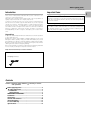
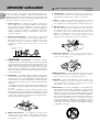
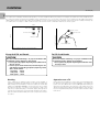
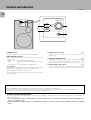
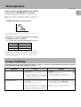
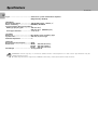
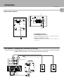
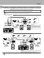
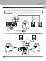
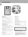
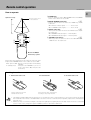
SW-305
SW-505D
➔ PAGE 2
➔ PAGE 13
POWERED SUBWOOFER
INSTRUCTION MANUAL
KENWOOD CORPORATION
B61-1073-00 (EN)
Before applying power
Caution : Read this page carefully to ensure safe operation.
SW-305 [EN]
Units are designed for operation as follows.
2
U.S.A. and Canada ................................................................... AC 120 V only
Europe and U.K. ........................................................................ AC 230 V only
Safety precautions
WARNING : TO PREVENT FIRE OR ELECTRIC SHOCK, DO NOT EXPOSE THIS
APPLIANCE TO RAIN OR MOISTURE.
CAUTION
RISK OF ELECTRIC SHOCK
DO NOT OPEN
CAUTION: TO REDUCE THE RISK OF ELECTRIC SHOCK, DO NOT REMOVE COVER
(OR BACK). NO USER-SERVICEABLE PARTS INSIDE. REFER SERVICING TO QUALIFIED SERVICE PERSONNEL.
THE LIGHTNING FLASH WITH ARROWHEAD SYMBOL, WITHIN AN EQUILATERAL TRIANGLE, IS INTENDED
TO ALERT THE USER TO THE PRESENCE OF UNINSULATED “DANGEROUS VOLTAGE” WITHIN THE
PRODUCT’S ENCLOSURE THAT MAY BE OF SUFFICIENT MAGNITUDE TO CONSTITUTE A RISK OF ELECTRIC SHOCK TO PERSONS.
THE EXCLAMATION POINT WITHIN AN EQUILATERAL TRIANGLE IS INTENDED TO ALERT THE USER TO
THE PRESENCE OF IMPORTANT OPERATING AND MAINTENANCE (SERVICING) INSTRUCTIONS IN THE
LITERATURE ACCOMPANYING THE APPLIANCE.
Before applying power
SW-305 [EN]
Introduction
Important Items
Your choice of this product indicates that you are a devotee to excellence in sound reproduction.
We appreciate your patronage and take pride in the long tradition of
quality components that our company represents.
So that you can get the most out of your unit, we suggest that you
take the time to read through this manual before you hook up and
operate your system. This will acquaint you with operating features
and system-connection considerations so that your listening pleasure will be enhanced right from the start. You will notice that in all
aspects of planning, engineering, styling, operating convenience
and adaptability we have sought to anticipate your needs and desires.
Unpacking
Unpack the unit carefully and make sure that all accessories are put aside
so they will not be lost.
Examine the unit for any possibility of shipping damage. If your unit is
damaged or fails to operate, notify your dealer immediately. If your unit
was shipped to you directly, notify the shipping company without delay.
Only the consignee (the person or company receiving the unit) can file a
claim against the carrier for shipping damage.
We recommend that you retain the original carton and packing materials
for use should you transport or ship the unit in the future.
Keep this manual handy for future reference.
Accessories
Pin-plug cord (1)
Contents
Caution : Read the pages marked
safe operation.
carefully to ensure
Before applying power .............................................................. 2
Safety precautions ................................................................ 2
Introduction ............................................................................ 3
Important Items ..................................................................... 3
IMPORTANT SAFEGUARDS ....................................................... 4
Installation .................................................................................... 6
Connections .................................................................................. 7
Controls and indicators ............................................................ 10
Sound adjustment ...................................................................... 11
In case of difficulty ................................................................... 11
Specifications ............................................................................ 12
Maintenance of the unit
When the front panel or case becomes dirty, wipe with a soft, dry
cloth. Do not use thinner, benzine, alcohol, etc. for these agents may
cause discoloration.
In regard to contact cleaner
Do not use contact cleaners because it could cause a malfunction.
Be specially careful not to use contact cleaners containing oil, for
they may deform the plastic component.
3
IMPORTANT SAFEGUARDS
Caution : Read this page carefully to ensure safe operation.
SW-305 [EN]
4
Please read all of the safety and operating instructions
before operating this appliance. Adhere to all warnings on the
appliance and in the instruction manual. Follow all the safety and
operating instructions. These safety and operating instructions
should be retained for future reference.
1. Power sources – The appliance should be connected to a
power supply only of the type described in the instruction
manual or as marked on the appliance. If you are not sure of
the type of power supply to your home, consult your appliance
dealer or local power company. For appliances intended to
operate from battery power, or other sources, refer to the
instruction manual.
2. Power-cord protection – Power-supply cords should
be routed so that they are not likely to be walked on or
pinched by items placed upon or against them, pay
particular attention to cords at plugs, convenience
receptacles, and the point where they exit from the
appliance.
6. Temperature – The appliance may not function properly
if used at extremely low, or freezing temperatures. The
ideal ambient temperature is above +5°C (41°F).
7. Heat – The appliance should be situated away from heat
sources such as radiators, heat registers, stoves, or
other appliances (including amplifiers) that produce heat.
8. Electric shock – Care should be taken so that objects do
not fall and liquid is not spilled into the enclosure
through openings. If a metal objects, such as a hair pin
or a needle, comes into contact with the inside of this
appliance, a dangerous electric shock may result. For
families with children, never permit children to put
anything, especially metal, inside this appliance.
Never pull or stretch
the cord.
9. Enclosure removal – Never remove the enclosure. If
the internal parts are touched accidentally, a serious
electric shock might occur.
3.
CAUTION – Polarization – This appliance may be
equipped with a polarized alternating-current line plug (a plug
having one blade wider than the other). This plug will fit into the
power outlet only one way. This is a safety feature. If you are
unable to insert the plug fully into the outlet, try reversing the
plug. If the plug should still fail to fit, contact your electrician to
replace your obsolete outlet. Do not defeat the safety purpose
of the polarized plug.
4. Ventilation – Slots and openings in the cabinet are provided
for ventilation and to ensure reliable operation of the appliance
and to protect it from overheating, and these openings must
not be blocked or covered. The appliance should be situated so
that its location or position does not interfere with its proper
ventilation.
To maintain good ventilation, do not put records or a table-cloth
on the appliance. Place the appliance at least 10 cm away from
the walls.
Do not use the appliance on a bed, sofa, rug or similar surface
that may block the ventilation openings. This appliance should
not be placed in a built-in installation such as a bookcase or rack
unless proper ventilation is provided or the manufacturer’s
instructions have been adhered to.
5. Water and moisture – The appliance should not be
used near water - for example, near a bathtub, washbowl,
kitchen sink, laundry tub, in a wet basement, or near a
swimming pool, etc.
10.Magnetic fields – Keep the appliance away from sources
of magnetic fields such as TV sets, speaker systems,
radios, motorized toys or magnetized objects.
11.Cleaning – Unplug this appliance from the wall outlet
before cleaning. Do not use volatile solvents such as
alcohol, paint thinner, gasoline, or benzine, etc. to clean
the cabinet. Use a clean dry cloth.
12.Accessories – Do not place this appliance on an unstable cart,
stand, tripod, bracket, or table. The appliance may fall, causing
serious injury to a child or adult, and serious damage to the
appliance. Use only with a cart, stand, tripod, bracket, or table
recommended by the manufacturer, or sold with the appliance.
Any mounting of the appliance should follow the manufacturer’s
instructions, and should use a mounting accessory
recommended by the manufacturer. An appliance and cart
combination should be moved with care. Quick stops, excessive
force, and uneven surfaces may cause the appliance and cart
combination to overturn.
Caution : Read this page carefully to ensure safe operation.
IMPORTANT SAFEGUARDS
SW-305 [EN]
13.Lightning – For added protection for this appliance during a
lightning storm, or when it is left unattended and unused for
long periods of time, unplug it from the wall outlet and
disconnect the antenna or cable system. This will prevent
damage to the appliance due to lightning and power-line
surges.
18.Power lines – An outside antenna system should not be
located in the vicinity of overhead power lines or other electric
light or power circuits, or where it can fall into such power lines
or circuits. When installing an outside antenna system, extreme
care should be taken to keep from touching such power lines
or circuits as contact with them might be fatal.
14.Abnormal smell – If an abnormal smell or smoke is
detected, immediately turn the power OFF and unplug
the appliance from the wall outlet. Contact your dealer or
nearest service center.
19.AC outlets – Do not connect other audio equipment
with a power consumption larger than that specified to
the AC outlet on the rear panel. Never connect other
electrical appliances, such as an iron or toaster, to it to
prevent fire or electric shock.
15.Damage requiring service – The appliance should be
serviced by qualified service personnel when:
A. The power-supply cord or the plug has been damaged.
B. Objects have fallen, or liquid has been spilled into
the appliance.
C. The appliance has been exposed to rain or water.
D. The appliance does not appear to operate normally
by following the instruction manual. Adjust only those controls
that are covered by the instruction manual as an improper
adjustment of other controls may result in damage and will
often require extensive work by a qualified technician to
restore the appliance to its normal operation.
E. The appliance has been dropped, or the enclosure
damaged.
F. The appliance exhibits a marked change in performance.
16.Servicing – The user should not attempt to service the
appliance beyond that described in the instruction
manual. All other servicing should be referred to qualified
service personnel.
20. Overloading – Do not overload wall outlets, extension cords,
or integral convenience receptacles as this can result in a risk
of fire or electric shock.
21. Attachment – Do not use attachments not recommended by
the appliance manufacturer as they may cause hazards.
22. Replacement parts – When replacement parts are required,
be sure the service technician has used replacement parts
specified by the manufacturer or have the same characteristics
as the original parts. Unauthorized substitutions may result in
fire, electric shock, or other hazards.
23. Safety check – Upon completion of any service or repairs to
this appliance, ask the service technician to perform safety
checks to determine that the appliance is in proper operating
condition.
17.Outdoor antenna grounding – If an outside antenna is
connected to the appliance, be sure the antenna system
is grounded so as to provide some protection against
voltage surges and built up static charges. Article 810 of
the National Electrical Code ANSI/NFPA 70, provides
information with respect to proper grounding of the
mast and supporting structure, grounding of the lead-in
wire to an antenna discharge unit, size of grounding
conductors, location of antenna discharge unit,
connection to grounding electrodes, and requirements
for the grounding electrode. See Figure.
EXAMPLE OF ANTENNA GROUNDING AS PER NATIONAL
ELECTRICAL CODE
ANTENNA
LEAD IN WIRE
GROUND
CLAMPS
ANTENNA
DISCHARGE UNIT
(NEC SECTION 810-20)
ELECTRIC
SERVICE
EQUIPMENT
GROUNDING CONDUCTORS
(NEC SECTION 810-21)
GROUND CLAMP
POWER SERVICE GROUNDING
ELECTRODE SYSTEM
(NEC ART 250, PART H)
NEC – NATIONAL ELECTRICAL CODE
Notes:
1. Item 3 is not required except for grounded or polarized equipment.
2. Item 17 and 18 are not required except for units provided with
antenna terminals.
3. Item 17 complies with UL in the U.S.A.
5
Installation
SW-305 [EN]
6
The Subwoofer is a virtually omnidirectional speaker, so it can be installed in almost any location. For example, the Subwoofer can be installed next to
the component system (consisting of an amplifier, tuner, cassette deck, etc.), or in a corner of the room, etc. The Subwoofer’s deep-bass reproduction
characteristics are richest when the Subwoofer is installed in a corner or near a wall. Since the low-bass component in music is usually monaural, only
one Subwoofer is necessary to obtain a sufficient stereo effect when used in combination with a stereo music system.
Wall
Near the wall
Near the corner
Sound Pressure Level
Near the corner
Near the wall
Wall
Wall
Far from the wall
Far from the wall
Speaker installation position, viewed from above
Except for U.S.A. and Canada
Frequency
For U.S.A. and Canada
CAUTION
CAUTION
Be sure to adhere followings. Or proper ventilation will
be blocked causing damage or fire hazard.
÷ Do not place any objects impairing heat radiation onto
the top of unit.
÷ Leave a space around the unit (from the largest outside dimension including projection) equal or greater
than, shown below.
Top panel : 50 cm
Side panel : 10 cm
Back panel : 10 cm
Be sure to adhere followings. Or proper ventilation will
be blocked causing damage or fire hazard.
÷ Do not place any objects impairing heat radiation onto
the top of unit.
Howling
Operation near a TV
If the Subwoofer is installed near an analog record turntable, a
howling sound may be generated. If this occurs, place the Subwoofer
farther away from the turntable or reduce the Subwoofer volume (By
rotating the VOLUME CONTROL counterclock-wise). The howling
phenomenon may also occur due to cross interference with a cassette deck, compact disc player, or Laserdisc player, although this is
very rare. If sound or picture seems to be distorted due to this reason,
place the Subwoofer farther away from other components or reduce
its volume.
If the Subwoofer is installed too close to a TV, color irregularities may
be observed on the TV screen. If such irregularities occur, switch the
power of the TV to OFF and then switch it ON again after waiting for
a period of 15 to 30 minutes. The influence of the Subwoofer on the
TV picture may be improved by self-demagnetization of the TV set. If
the color irregularities still persist, move the Subwoofer farther away
from the TV.
Connections
SW-305 [EN]
7
Input/output terminals
LINE
R
LINE
R
(MONO)
INPUT
L
(MONO)
INPUT
+
+
L
R
L
R
-
3
L
-
-
-
R
R
+
+
FROM
AMPLIFIER
INPUT
TO
SPEAKERS
OUTPUT
+
R
L
-
+
R
L
-
R
+
R
+
FROM
TO
AMPLIFIER SPEAKERS
INPUT
OUTPUT
1
Power cord
To WALL AC OUTLET
2
1 FROM AMPLIFIER INPUT terminals
These terminals are used to connect the FRONT SPEAKER terminals of the amplifier to this unit.
2 TO SPEAKERS OUTPUT terminals
3 LINE jacks (RCA-type pin-plug)
These jacks are used to connect the Subwoofer Pre-Out jacks of
the amplifier.
If the amplifier is equipped with a Subwoofer Pre-Out jack
Before connection: Set the POWER switches of the amplifier and Subwoofer to OFF. If they are connected with the
POWER switch(es) left ON, one or both components may be damaged.
Speaker cord (Commercially available parts)
FRONT SPEAKERS
SW-305
SUBWOOFER
CENTER SPEAKERS
+
Speaker terminals
(Amplifier or Receiver)
LINE
R
L
(MONO)
INPUT
–
+
+
L
R
L
R
-
-
-
-
R
R
+
FROM
AMPLIFIER
INPUT
+
TO
SPEAKERS
OUTPUT
–
SUBWOOFER
PRE OUT
LINE
R
Front speaker (R)
L
(MONO)
INPUT
SUB WOOFER PRE OUT
+
R (MONO)
–
+
Front speaker (L)
Connections
SW-305 [EN]
8
If the amplifier is not equipped with a Subwoofer Pre-Out jack or if two subwoofers are to be used
Before connection: Set the POWER switches of the amplifier and Subwoofer to OFF. If they are connected with the
POWER switch(es) left ON, one or both components may be damaged.
When connecting the Subwoofer to the amplifier, be sure to always connect the “+” terminals to “+” terminals and the “–”
terminals to “–” terminals. If terminals are connected incorrectly, the amplifier may be damaged.
Speaker cords are not supplied, Please use a speaker cords with thick conductor.
Note
Using one subwoofer
Speaker cord (Commercially available parts)
+
+
L
R
L
R
-
-
-
-
R
R
+
CAUTION
The front speakers
connected with the
Subwoofer should
have the impedance
specified by the amplifier or receiver in
use.
+
FROM
AMPLIFIER
INPUT
TO
SPEAKERS
OUTPUT
LINE
R
L
(MONO)
INPUT
1
+
+
L
R
L
R
-
FRONT SPEAKERS
CENTER SPEAKERS
R
+
Twist wire’s
conductor
+
FROM
AMPLIFIER
INPUT
+
3
-
R
TO
SPEAKERS
OUTPUT
2
Insert the
conductor
4
Release
Push
–
SW-305 SUBWOOFER
Speaker terminals
(Amplifier or Receiver)
Speaker cord
(Commercially
available parts)
–
–
+
Front speaker (R)
+
Front speaker (L)
Using two subwoofers
Speaker cord (Commercially available parts)
+
+
L
R
L
R
+
+
L
R
L
R
-
-
-
-
R
LINE
R
+
FROM
AMPLIFIER
INPUT
L
+
+
L
R
-
CENTER SPEAKERS
+
FROM
AMPLIFIER
INPUT
TO
SPEAKERS
OUTPUT
+
Speaker terminals
(Amplifier or Receiver)
TO
SPEAKERS
OUTPUT
(MONO)
INPUT
L
R
R
+
FRONT SPEAKERS
R
+
-
R
LINE
R
L
(MONO)
INPUT
–
-
+
+
L
R
L
R
-
-
-
-
-
-
R
R
R
R
+
+
+
FROM
AMPLIFIER
INPUT
TO
SPEAKERS
OUTPUT
FROM
AMPLIFIER
INPUT
–
SW-305
SUBWOOFER
(Right channel)
+
–
SW-305
SUBWOOFER
(Left channel)
Front speaker (R)
1
Twist wire’s
conductor
+
TO
SPEAKERS
OUTPUT
2
3
Push
4
Insert the conductor
+
Front speaker (L)
Release
CAUTION
The front speakers connected with the Subwoofer should have the impedance specified by the amplifier or receiver in use.
Note
When the amplifier has two stereo speaker output circuits which can output signals simultaneously, the front speakers do not have
to be connected through the subwoofer(s) but can be connected directly to the amplifier, whether the number of subwoofers used
is one or two.
Connections
SW-305 [EN]
9
Using the Pre-Out jacks
Before connection: Set the POWER switches of the amplifier and Subwoofer to OFF. If they are connected with the
POWER switch(es) left ON, one or both components may be damaged.
When connecting the Subwoofer to the amplifier, be sure to always connect the “+” terminals to “+” terminals and the “–”
terminals to “–” terminals. If terminals are connected incorrectly, the amplifier may be damaged.
Using one subwoofer
SW-305
SUBWOOFER
FRONT SPEAKERS
CENTER SPEAKERS
Speaker terminals
(Amplifier or Receiver)
Speaker cord (Commercially available parts)
+
LINE
R
L
(MONO)
INPUT
+
R
L
-
R
+
+
FROM
AMPLIFIER
INPUT
–
+
R
L
R
TO
SPEAKERS
OUTPUT
–
+
–
Front speaker (R)
+
Front speaker (L)
LINE
R
L
(MONO)
INPUT
Pin-plug cord
(Commercially available parts)
PRE OUT
L
R
Using two subwoofers
–
+
Speaker cord
(Commercially available parts)
Front speaker (R)
SW-305
SUBWOOFER
(Right channel)
SW-305
SUBWOOFER
(Left channel)
CENTER SPEAKERS
+
Speaker terminals
(Amplifier or Receiver)
L
(MONO)
INPUT
+
+
L
R
L
R
-
+
Front speaker (L)
FRONT SPEAKERS
LINE
R
–
LINE
R
L
(MONO)
INPUT
–
-
+
+
L
R
L
R
-
-
-
-
-
-
R
R
R
R
+
+
+
FROM
AMPLIFIER
INPUT
TO
SPEAKERS
OUTPUT
FROM
AMPLIFIER
INPUT
+
TO
SPEAKERS
OUTPUT
LINE
PRE OUT
R
LINE
L
R
(MONO)
INPUT
L
L
(MONO)
INPUT
R
Pin-plug cord (Commercially available parts)
Note
The subwoofer(s) can also be connected to the REC OUT or LINE OUT jacks of the amplifier in the same way as above. In this case,
however, the volume of the subwoofer(s) cannot be interlocked with the amplifier volume. (Every time the amplifier volume is varied,
the subwoofer volume should also be varied.)
Controls and indicators
SW-305 [EN]
10
VOLUME CONTROL
POWER
1
4
ON/STANDBY
-
2
ON
–
OFF
PHASE
MIN
3
–
NORMAL
-
REVERSE
MAX
CROSSOVER
5
60Hz
1 POWER switch
Press to switch the power to the Subwoofer ON/OFF.
2 ON/STANDBY indicator
Lights up according to the operation modes of this unit as described below.
Green ................ Power ON (Operating status)
Amber ............... Standby mode initiated by Auto Shut-off function
Extinguished .... Power OFF or power supply failure
Auto Shut-off.
The Subwoofer automatically returns to STANDBY mode (amber
light) when no signal has been input for about 8 minutes.
When standby is initiated by Auto Shut-off:
The unit turns ON (operating status) again in a few seconds after
a signal is input.
200Hz
3 PHASE selector switch
!
Press to switch the phase of the sound output from the
Subwoofer.
4 VOLUME CONTROL knob
!
Adjusts the volume level of the output of the Subwoofer. Rotating the knob clockwise increases the volume level, and rotating
the knob counterclockwise decreases the volume level.
5 CROSSOVER control knob
!
Turn the control knob to adjust the cutoff frequency of the highfrequency components in the sound output from the Subwoofer.
Standby mode
When the STANDBY indicator is lit amber, it indicates that the power of the unit is in the Standby mode.
In the Standby mode, the audio output is cut off in order to prevent unnecessary noise from the subwoofer when no signal is input to it.
If the subwoofer is not to be used, turn its power off by pressing the POWER switch.
Caution concerning operation
An excessive input level to the Subwoofer may impair the sound quality or damage the unit. Careful attention should therefore be paid to the
following precautions.
1. Do not increase the output of the amplifier to a high level while the low-frequency level is enhanced by the amplifier’s tone
control or loudness control.
2. When operating the amplifier switches or when placing the stylus on an analog record, set the amplifier volume to its minimum
level.
Sound adjustment
SW-305 [EN]
How to use the VOLUME CONTROL knob, PHASE
selector switch, CROSSOVER control knob
11
The VOLUME CONTROL knob, PHASE selector switch and CROSSOVER control knob can be adjusted to match the condition of the
listening room and/or the characteristics of the left and right front
speakers.
Sound Pressure Level
CROSSOVER control knob function
CROSSOVER control knob
Frequency
The characteristics above express the images and the details are different
from the actual characteristics.
Examples of standard adjustment according
to the type of front speakers
Crossover frequency adjustment (CROSSOVER control knob)
Front speaker
Small speaker
Crossover Frequency
120 ~ 200 Hz
Medium speaker
80 ~ 120 Hz
Large speaker
60 ~ 80 Hz
Depending on the listening room condition and the front speaker
characteristics, other adjustment setting than the examples shown
above may provide more natural bass sound and more effective bass
reproduction. Try various adjustment settings to select the optimum
one for your listening room.
In case of difficulty
A simple mistake may often be misunderstood as a failure. In case of a trouble, check the applicable symptom
in the following table before calling for service.
Symptom
No sound is output.
Sound volume is low.
Cause
Remedy
÷ The connection cords are not plugged into the
jacks properly.
÷ The volume is set to the minimum.
÷ The connected amplifier or receiver does not
output the subwoofer pre-out signal (applicable when the amplifier or receiver is equipped
with the pre-out on/off function).
÷ Connect them properly by referring to “Connections”.
÷ Adjust to an optimum volume.
÷ Switch the subwoofer pre-out switch of the
connected amplifier or receiver to ON.
÷ The speaker cords are connected in the reverse phase.
÷ The phase selection is not correct.
÷ Connect the R and L cords with correct + and
- polarity by referring to “Connections”.
÷ Set the PHASE switch to a different phase.
÷ The pre-out signal level of the connected amplifier or receiver is set to the minimum (applicable when the amplifier or receiver is equipped
with the pre-out level control function).
÷ Adjust the pre-out level of the connected amplifier or receiver to an optimum level.
7
0
7
0
Specifications
SW-305 [EN]
12
Type .................................................... Subwoofer system with built-in amplifier
(Magnetically shielded)
[Amplifier]
Rated Output Power ........................ 100 W RMS 30 Hz ~ 200 Hz, 4 Ω
Phase Switching ............................... NORMAL, REVERSE
Input Sensitivity & Input Impedance
RCA-type pin-plug jack ................. 100 mV /12 kΩ
200 mV /12 kΩ (MONO Input)
Push-type terminals ...................... 1.7 V /15 kΩ
[Speaker]
Enclosure ........................................... Bass-Reflex, Floor Standing Type
Speaker Unit ..................................... 200 mm (8") Cone type
Nominal Impedance ......................... 4 Ω
[General]
Rated Power Consumption ............ 90 W
Dimensions ........................................ Width
Height
Depth
Net Weight ........................................ 12.2 kg
Notes
: 250 mm (9-13/16")
: 422 mm (16-5/8")
: 408 mm (16-1/16")
(26.9 lb)
KENWOOD follows a policy of continuous advancements in development. For this reason specifications may be
changed without notice.
¶ Sufficient performance may not be exhibited at extremely cold locations (where water freezes).
SW-505D
POWERED SUBWOOFER
INSTRUCTION MANUAL
KENWOOD CORPORATION
B61-1183-00 (EN)
Before applying power
Caution : Read this page carefully to ensure safe operation.
SW-505D (EN)
Units are designed for operation as follows.
U.S.A. and Canada ................................................................... AC 120 V only
Europe ........................................................................................ AC 230 V only
ITALIANO
NEDERLANDS
DEUTSCH
FRANÇAIS
14
Safety precautions
WARNING : TO PREVENT FIRE OR ELECTRIC SHOCK, DO NOT EXPOSE THIS
APPLIANCE TO RAIN OR MOISTURE.
CAUTION
ESPAÑOL
RISK OF ELECTRIC SHOCK
DO NOT OPEN
CAUTION: TO REDUCE THE RISK OF ELECTRIC SHOCK, DO NOT REMOVE COVER
(OR BACK). NO USER-SERVICEABLE PARTS INSIDE. REFER SERVICING TO QUALIFIED SERVICE PERSONNEL.
THE LIGHTNING FLASH WITH ARROWHEAD SYMBOL, WITHIN AN EQUILATERAL TRIANGLE, IS INTENDED
TO ALERT THE USER TO THE PRESENCE OF UNINSULATED “DANGEROUS VOLTAGE” WITHIN THE
PRODUCT’S ENCLOSURE THAT MAY BE OF SUFFICIENT MAGNITUDE TO CONSTITUTE A RISK OF ELECTRIC SHOCK TO PERSONS.
THE EXCLAMATION POINT WITHIN AN EQUILATERAL TRIANGLE IS INTENDED TO ALERT THE USER TO
THE PRESENCE OF IMPORTANT OPERATING AND MAINTENANCE (SERVICING) INSTRUCTIONS IN THE
LITERATURE ACCOMPANYING THE APPLIANCE.
Before applying power
SW-505D (EN)
Introduction
Important Items
Your choice of this product indicates that you are a devotee to excellence in sound reproduction.
We appreciate your patronage and take pride in the long tradition of
quality components that our company represents.
So that you can get the most out of your unit, we suggest that you
take the time to read through this manual before you hook up and
operate your system. This will acquaint you with operating features
and system-connection considerations so that your listening pleasure will be enhanced right from the start. You will notice that in all
aspects of planning, engineering, styling, operating convenience
and adaptability we have sought to anticipate your needs and desires.
For the U.S.A.
This equipment may generate or use radio frequency energy. Changes
or modifications to this equipment may cause harmful interference
unless the modifications are expressly approved in the instruction
manual. The user could lose the authority to operate this equipment
if an unauthorized change or modification is made.
NOTE:
This equipment has been tested and found to comply with the limits
for a Class B digital device, pursuant to Part 15 of the FCC Rules.
These limits are designed to provide reasonable protection against
harmful interference in a residential installation. This equipment may
cause harmful interference to radio communications, if it is not
installed and used in accordance with the instructions. However,
there is no guarantee that interference will not occur in a particular
installation. If this equipment does cause harmful interference to
radio or television reception, which can be determined by turning the
equipment off and on, the user is encouraged to try to correct the
interference by one or more of the following measures:
– – Reorient or relocate the receiving antenna.
– – Increase the separation between the equipment and receiver.
– – Connect the equipment into an outlet on a circuit different from
that to which the receiver is connected.
– – Consult the dealer or an experienced radio / TV technician for help.
Keep this manual handy for future reference.
Accessories
REMOTE CONTROL UNIT RC-W0502
MUSIC/CINEMA
PHASE
When the front panel or case becomes dirty, wipe with a soft, dry
cloth. Do not use thinner, benzine, alcohol, etc. for these agents may
cause discoloration.
In regard to contact cleaner
Do not use contact cleaners because it could cause a malfunction.
Be specially careful not to use contact cleaners containing oil, for
they may deform the plastic component.
Batteries (R03/ AAA)
NEDERLANDS
VOLUME
Remote control unit (1)
POWER
Pin-plug cord (1)
Maintenance of the unit
DEUTSCH
Unpack the unit carefully and make sure that all accessories are put aside
so they will not be lost.
Examine the unit for any possibility of shipping damage. If your unit is
damaged or fails to operate, notify your dealer immediately. If your unit
was shipped to you directly, notify the shipping company without delay.
Only the consignee (the person or company receiving the unit) can file a
claim against the carrier for shipping damage.
We recommend that you retain the original carton and packing materials
for use should you transport or ship the unit in the future.
FCC WARNING
FRANÇAIS
Unpacking
15
ITALIANO
Caution : Read the pages marked
safe operation.
carefully to ensure
Before applying power ............................................................ 14
Safety precautions .............................................................. 14
Introduction .......................................................................... 15
Important Items ................................................................... 15
Installation .................................................................................. 16
Connections ................................................................................ 17
Controls and indicators ............................................................ 20
Remote control operation ........................................................ 21
Sound adjustment ...................................................................... 22
In case of difficulty ................................................................... 22
Specifications ............................................................................ 23
ESPAÑOL
Contents
Installation
SW-505D (EN)
16
The Subwoofer is a virtually omnidirectional speaker, so it can be installed in almost any location. For example, the Subwoofer can be installed next to
the component system (consisting of an amplifier, tuner, cassette deck, etc.), or in a corner of the room, etc. The Subwoofer’s deep-bass reproduction
characteristics are richest when the Subwoofer is installed in a corner or near a wall. Since the low-bass component in music is usually monaural, only
one Subwoofer is necessary to obtain a sufficient stereo effect when used in combination with a stereo music system.
Wall
Near the wall
Near the corner
Sound Pressure Level
FRANÇAIS
Near the corner
Near the wall
Wall
Wall
Far from the wall
Far from the wall
ESPAÑOL
ITALIANO
NEDERLANDS
DEUTSCH
Speaker installation position, viewed from above
Except for U.S.A. and Canada
Frequency
For U.S.A. and Canada
CAUTION
CAUTION
Be sure to adhere followings. Or proper ventilation will
be blocked causing damage or fire hazard.
÷ Do not place any objects impairing heat radiation onto
the top of unit.
÷ Leave a space around the unit (from the largest outside dimension including projection) equal or greater
than, shown below.
Top panel : 50 cm
Side panel : 10 cm
Back panel : 10 cm
Be sure to adhere followings. Or proper ventilation will
be blocked causing damage or fire hazard.
÷ Do not place any objects impairing heat radiation onto
the top of unit.
Howling
Operation near a TV
If the Subwoofer is installed near an analog record turntable, a
howling sound may be generated. If this occurs, place the Subwoofer
farther away from the turntable or reduce the Subwoofer volume (By
rotating the VOLUME CONTROL counterclock-wise). The howling
phenomenon may also occur due to cross interference with a cassette deck, compact disc player, or Laserdisc player, although this is
very rare. If sound or picture seems to be distorted due to this reason,
place the Subwoofer farther away from other components or reduce
its volume.
If the Subwoofer is installed too close to a TV, color irregularities may
be observed on the TV screen. If such irregularities occur, switch the
power of the TV to OFF and then switch it ON again after waiting for
a period of 15 to 30 minutes. The influence of the Subwoofer on the
TV picture may be improved by self-demagnetization of the TV set. If
the color irregularities still persist, move the Subwoofer farther away
from the TV.
Interference in radio broadcasts
This unit employs digital circuitry to amplify signals with high efficiency. As a result, when a radio receiver such as an audio receiver or
tuner is installed near this unit, the reception may be interfered with
by noise. In such a case, install this unit and radio receiver at a larger
distance.
¶ If the radio reception is still interfered with by noise even when the
power of this unit is switched off or the volume is minimized, the
interference is not due to this unit.
¶ When the indoor antenna of the audio receiver or tuner can be
installed apart from this unit, install the antenna as apart as possible
from this unit. Also distribute the antenna cable as apart as possible
from this unit.
Connections
SW-505D (EN)
17
Input/output terminals
2
INPUT
FROM
- L +
AMPLIFIER + R -
LINE
L
INPUT
FROM
AMPLIFIER
+ R -
- L +
TO
SPEAKERS
+ R -
- L +
LINE
R
L
R
TO
SPEAKERS + R -
(MONO)
OUTPUT
(MONO)
- L +
OUTPUT
FRANÇAIS
13
These terminals are used to connect the FRONT SPEAKER terminals of the amplifier to this unit.
Power cord
To wall AC outlet
3 LINE jacks (RCA-type pin-plug)
Before connection: Set the POWER switches of the amplifier and Subwoofer to OFF. If they are connected with the
POWER switch(es) left ON, one or both components may be damaged.
ESPAÑOL
Speaker cord (Commercially available parts)
B
FRONT SPEAKERS
L (6 — 16‰)R
Speaker terminals
(Amplifier or Receiver)
A
L
SW-505D
SUBWOOFER
+
–
INPUT
FROM
AMPLIFIER
+ R -
- L +
TO
SPEAKERS
+ R -
- L +
LINE
L
R
(MONO)
OUTPUT
–
REC
OUT
CD2/
TAPE2
MONITOR
SUB
WOOFER
SUBWOOFER
PRE OUT
+
Front speaker (R)
LINE
L
R
(MONO)
R (MONO)
ITALIANO
If the amplifier is equipped with a Subwoofer Pre-Out jack
NEDERLANDS
These jacks are used to connect the Subwoofer Pre-Out jacks of
the amplifier.
R
DEUTSCH
1 TO SPEAKERS terminals
2 FROM AMPLIFIER terminals
–
+
Front speaker (L)
Connections
SW-505D (EN)
18
If the amplifier is not equipped with a Subwoofer Pre-Out jack or if two subwoofers are to be used
Before connection: Set the POWER switches of the amplifier and Subwoofer to OFF. If they are connected with the
POWER switch(es) left ON, one or both components may be damaged.
When connecting the Subwoofer to the amplifier, be sure to always connect the “+” terminals to “+” terminals and the “–”
terminals to “–” terminals. If terminals are connected incorrectly, the amplifier may be damaged.
Speaker cords are not supplied, Please use a speaker cords with thick conductor.
Note
Using one subwoofer
FRANÇAIS
Speaker cord (Commercially available parts)
1
Twist wires
conductor
INPUT
FROM
AMPLIFIER
INPUT
FROM
AMPLIFIER
+ R -
- L +
+ R -
- L +
Insert the
conductor
LINE
L
2
R
TO
SPEAKERS
3
4
(MONO)
+ R -
- L +
OUTPUT
FRONT SPEAKERS
L (6 — 16‰)R
DEUTSCH
B
R
TO
SPEAKERS
A
L
+ R -
- L +
Release
Push
OUTPUT
+
–
Speaker terminals
(Amplifier or Receiver)
SW-505D
SUBWOOFER
NEDERLANDS
CAUTION
The front speakers connected
with the Subwoofer should
have the impedance specified
by the amplifier or receiver in
use.
Speaker cord
(Commercially
available parts)
–
–
+
+
Front speaker (L)
Front speaker (R)
ITALIANO
Using two subwoofers
1
2
Twist wires
conductor
+ R -
Push
4
Insert the conductor
Release
Speaker cord (Commercially available parts)
INPUT
FROM
AMPLIFIER
3
- L +
INPUT
LINE
FROM
AMPLIFIER
+ R -
- L +
TO
SPEAKERS
+ R -
- L +
ESPAÑOL
TO
SPEAKERS
R
(MONO)
+ R -
INPUT
- L +
OUTPUT
LINE
L
L
R
INPUT
FROM
AMPLIFIER
+ R -
- L +
TO
SPEAKERS
+ R -
- L +
Speaker terminals
(Amplifier or Receiver)
B
R
OUTPUT
FRONT SPEAKERS
L (6 — 16‰)R
FROM
AMPLIFIER
+ R -
- L +
TO
SPEAKERS
+ R -
- L +
(MONO)
OUTPUT
A
L
+
OUTPUT
–
SW-505D
SUBWOOFER
(Right channel)
SW-505D
SUBWOOFER
(Left channel)
–
+
Front speaker (R)
–
+
Front speaker (L)
CAUTION
The front speakers connected with the Subwoofer should have the
impedance specified by the amplifier or receiver in use.
Note
When the amplifier has two stereo speaker output circuits which can output signals simultaneously, the front speakers do not have
to be connected through the subwoofer(s) but can be connected directly to the amplifier, whether the number of subwoofers used
is one or two.
Connections
SW-505D (EN)
19
Using the Pre-Out jacks
Before connection: Set the POWER switches of the amplifier and Subwoofer to OFF. If they are connected with the
POWER switch(es) left ON, one or both components may be damaged.
When connecting the Subwoofer to the amplifier, be sure to always connect the “+” terminals to “+” terminals and the “–”
terminals to “–” terminals. If terminals are connected incorrectly, the amplifier may be damaged.
Using one subwoofer
FRONT SPEAKERS
L (6 — 16‰)R
FRANÇAIS
B
R
A
L
+
Speaker terminals
(Amplifier or Receiver)
Speaker cord
(Commercially
parts)
available
SW-505D
SUBWOOFER
–
INPUT
FROM
AMPLIFIER
+ R -
- L +
TO
SPEAKERS
+ R -
- L +
LINE
L
OUTPUT
–
+
–
+
PRE OUT
Front speaker (R)
L
DEUTSCH
R
(MONO)
Front speaker (L)
R
NEDERLANDS
LINE
Pin-plug cord (Commercially available parts)
L
R
(MONO)
Using two subwoofers
ITALIANO
Speaker cord
(Commercially available parts)
–
+
–
+
Front speaker (R)
Front speaker (L)
Speaker terminals
(Amplifier or Receiver)
R
FRONT SPEAKERS
L (6 — 16‰)R
+ R -
SW-505D
SUBWOOFER
(Left channel)
–
- L +
INPUT
LINE
L
R
TO
SPEAKERS
L
+
INPUT
FROM
AMPLIFIER
A
LINE
- L +
TO
SPEAKERS
+ R -
- L +
LINE
L
- L +
OUTPUT
+ R -
R
(MONO)
+ R -
FROM
AMPLIFIER
L
R
(MONO)
OUTPUT
(MONO)
LINE
L
R
(MONO)
PRE OUT
L
R
Pin-plug cord (Commercially available parts)
Note
The subwoofer(s) can also be connected to the REC OUT or LINE OUT jacks of the amplifier in the same way as above. In this case,
however, the volume of the subwoofer(s) cannot be interlocked with the amplifier volume. (Every time the amplifier volume is varied,
the subwoofer volume should also be varied.)
ESPAÑOL
B
SW-505D
SUBWOOFER
(Right channel)
Controls and indicators
SW-505D (EN)
20
VOLUME CONTROL
POWER
ON/STANDBY
1
-
2
ON
–
PEAK INDICATOR
3
4
MIN
MAX
SLOPE
12dB
0
MODE
5
FRANÇAIS
-
OFF
PHASE
6
MUSIC
24dB
=
CINEMA
CROSSOVER
NORMAL REVERSE
~
60Hz
200Hz
DEUTSCH
78 9 0
7 MUSIC indicator
1 POWER switch
Press to switch the power to the Subwoofer ON/OFF.
ITALIANO
NEDERLANDS
2 ON/STANDBY indicator
Lights up according to the operation modes of this unit as described below.
Green ................ Power ON (Operating status)
Red .................... Standby mode initiated by remote control
Amber ............... Standby mode initiated by Auto Shut-off function
Extinguished .... Power OFF or power supply failure
Auto Shut-off.
The Subwoofer automatically returns to STANDBY mode (amber
light) when no signal has been input for about 8 minutes.
When standby is initiated by Auto Shut-off:
The subwoofer returns to the power ON status (operating status) in a few seconds when a signal is input or when the power
key of the remote control unit is pressed.
3 Remote control sensor
ESPAÑOL
Receives the transmission from the remote control unit.
The brightness of this indicator varies according to the amplitude
of the low-frequency component in the input signal.
The PEAK INDICATOR indicator lights very brightly when the builtin amplifier of the Subwoofer is overdriven.
If the Subwoofer is used in this condition, the sound is distorted
and the Subwoofer itself may also fail. To prevent this, reduce the
volume of the Subwoofer or adjust the amplifier or receiver in
order to reduce the input signal to the Subwoofer.
5 MODE select key
This key selects the sound mode of the Subwoofer. The
Subwoofer incorporates the music and movie modes which can
provide optimum deep-bass reproduction characteristics for the
music source and movie audio respectively. Each press switches
the mode as follows.
When MUSIC indicator lights ................. music mode
When CINEMA indicator lights .............. movie mode
@
Each press of this key switches the phase of the sound output
from the Subwoofer.
When NORMAL indicator lights ...... Normal phase
When REVERSE indicator lights ...... Reverse phase
9 REVERSE indicator
0 CINEMA indicator
- VOLUME CONTROL knob
@
Adjusts the volume level of the output of the Subwoofer. Rotating the knob clockwise increases the volume level, and rotating
the knob counterclockwise decreases the volume level.
= SLOPE selector switch
@
This switch selects the attenuation characteristic of the sound
output from the Subwoofer.
~ CROSSOVER control knob
4 PEAK INDICATOR indicator
6 PHASE select key
8 NORMAL indicator
@
Turn the control knob to adjust the cutoff frequency of the highfrequency components in the sound output from the Subwoofer.
Standby mode
While the standby indicator of the unit is lit in red or amber, a small
amount of current is flowing into the unit’s internal circuitry to back up
the memory. This condition is referred to as the standby mode of the
unit. While the unit is in the standby mode, it can be turned ON from
the remote control unit.
Caution concerning operation
An excessive input level to the Subwoofer may impair the sound
quality or damage the unit. Careful attention should therefore be
paid to the following precautions.
1. Do not increase the output of the amplifier to a high level
while the low-frequency level is enhanced by the
amplifier’s tone control or loudness control.
2. When operating the amplifier switches or when placing the
stylus on an analog record, set the amplifier volume to its
minimum level.
Remote control operation
SW-505D (EN)
How to operate
21
1 POWER key
Operation range
Remote control sensor
on the Subwoofer
Press to switch the power ON/STANDBY when the POWER
switch of the Subwoofer set to ON.
2 MUSIC/CINEMA select key
0
This key has the same function as the MODE key on the
Subwoofer.
6m
30 °
When MUSIC indicator lights ................. music mode
When CINEMA indicator lights .............. movie mode
30 °
3 PHASE select key
0
POWER
2
3
1
4 VOLUME control key s
MUSIC/CINEMA
PHASE
VOLUME
0
÷ This keys have the same function as the VOLUME CONTROL knob on the Subwoofer.
4
FRANÇAIS
This key has the same function as the PHASE select key on
the Subwoofer.
When NORMAL indicator lights ...... Normal phase
When REVERSE indicator lights ...... Reverse phase
REMOTE CONTROL UNIT RC-W0502
DEUTSCH
Model : RC-W0502
Infrared ray system
NEDERLANDS
Plug in the power supply plug of the Subwoofer to the AC outlet
and press the POWER switch on the Subwoofer to turn ON.
When power is ON : Remote control operation is immediately
available.
In Standby mode : First press the POWER key of the remote control unit to ON, then press the
desired key.
1. Remove the back cover.
2. Insert batteries.
3. Close the back cover.
ITALIANO
Loading batteries
ESPAÑOL
Open by pushing the position
marked with the arrow.
Notes
Insert two R03 (”AAA”-size) batteries
according to the polarity indication.
1. The batteries initially supplied are intended for use in checking the remote control operations, so their service life may be shorter
than usual. When the remote controllable distance shortens or remote control becomes impossible, replace both of the batteries
with new ones.
2. Malfunction may occur if direct sunlight or the light of a highfrequency lighting fluorescent lamp enters the remote control light
sensor. In such a case, change the system installation position to prevent the malfunction.
Sound adjustment
SW-505D (EN)
The VOLUME CONTROL knob, PHASE select key, CROSSOVER
control knob and SLOPE selector switch can be adjusted to match
the condition of the listening room and/or the characteristics of the
left and right front speakers.
ITALIANO
NEDERLANDS
DEUTSCH
Sound Pressure Level
Sound Pressure Level
FRANÇAIS
CROSSOVER control knob and SLOPE selector switch function
CROSSOVER control knob
Frequency
24dB
12dB
SLOPE selector switch
Frequency
The characteristics above express the images and the details are
different from the actual characteristics.
Examples of standard adjustment according
to the type of front speakers
1 Crossover frequency adjustment (CROSSOVER control
knob)
Front speaker
Note
Small speaker
Crossover Frequency
120 ~ 200 Hz
Medium speaker
80 ~ 120 Hz
Large speaker
60 ~ 80 Hz
24 dB position: To be used when the Subwoofer is combined
with bass-reflex type front speakers.
Front speaker
Bass-reflex type
Frequency
12 dB position: To be used when the Subwoofer is combined
with acoustic air-suspension type front speakers.
Front speaker
Acustic Air Suspencion type
Frequency
0 (dB) position: To be used for reproducing sound from the
subwoofer without electrically attenuating the
high-frequency components in the input signal.
Use this position when the high frequencies in
the subwoofer signal have already been cut by
the Dolby Digital or DTS circuitry.
The crossover frequency adjustment is invalid
when this position is set.
Depending on the listening room condition and the front speaker characteristics, other adjustment setting than the examples shown above may
provide more natural bass sound and more effective bass reproduction. Try various adjustment settings to select the optimum one for your
listening room.
In case of difficulty
A simple mistake may often be misunderstood as a failure. In case of a trouble, check the applicable symptom
in the following table before calling for service.
Symptom
ESPAÑOL
0 (dB)
2 Crossover slope adjustment (SLOPE selector switch)
Sound Pressure Level
How to use the VOLUME CONTROL knob,
PHASE select key, CROSSOVER control knob
and SLOPE selector switch
Sound Pressure Level
22
Cause
Remedy
No sound is output.
÷ The connection cords are not plugged into the
jacks properly.
÷ The volume is set to the minimum.
÷ The connected amplifier or receiver does not
output the subwoofer pre-out signal (applicable when the amplifier or receiver is equipped
with the pre-out on/off function).
÷ Connect them properly by referring to “Connections”.
7
0!
÷ Adjust to an optimum volume.
÷ Switch the subwoofer pre-out switch of the
connected amplifier or receiver to ON.
Sound volume is low.
÷ The speaker cords are connected in the reverse phase.
÷ The phase selection is not correct.
÷ The pre-out signal level of the connected amplifier or receiver is set to the minimum (applicable when the amplifier or receiver is equipped
with the pre-out level control function).
÷ Connect the R and L cords with correct + and
- polarity by referring to “Connections”.
7
0!
÷ Set the phase to a different phase.
÷ Adjust the pre-out level of the connected amplifier or receiver to an optimum level.
Radio broadcasts are interfered
with by noise.
÷ The interfered unit is installed near the
subwoofer.
÷ Install the subwoofer more apart from the radio
receiver.
6
Specifications
SW-505D (EN)
23
Type .................................................... Subwoofer system with built-in amplifier
(Magnetically shielded)
[Amplifier]
Rated Output Power ........................ 150 W RMS 30 Hz ~ 200 Hz, 4 Ω
Phase Switching ............................... NORMAL, REVERSE
Input Sensitivity & Input Impedance
RCA-type pin-plug jack ................. 100 mV /12 kΩ
200 mV /12 kΩ (MONO Input)
Push-type terminals ...................... 1.7 V /15 kΩ
[General]
Rated Power Consumption ............ 50 W
Dimensions ........................................ Width
Height
Depth
Net Weight ........................................ 15.2 kg
KENWOOD follows a policy of continuous advancements in development. For this reason specifications may be
changed without notice.
¶ Sufficient performance may not be exhibited at extremely cold locations (where water freezes).
DEUTSCH
Note
: 294 mm (11-9/16")
: 457 mm (18")
: 415 mm (16-5/16")
(33.5 lb)
FRANÇAIS
[Speaker]
Enclosure ........................................... Bass-Reflex, Floor Standing Type
Speaker Unit ..................................... 250 mm(10") Cone type
Nominal Impedance ......................... 4 Ω
NEDERLANDS
ITALIANO
ESPAÑOL
SW-505D (EN)
ESPAÑOL
ITALIANO
NEDERLANDS
DEUTSCH
FRANÇAIS
24
For your records
Record the serial number, found on the back of the unit, in the spaces
designated on the warranty card, and in the space provided below. Refer to the model and serial numbers whenever you call upon your dealer
for information or service on this product.
Model ____________________
Serial Number _____________________