1
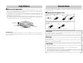
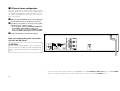
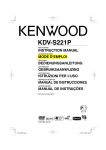
User’s Guide
MX-5000
PO
W
R
E
IFIER
PL
AM
B60-5163-08 01 KO (K) CR 0103
Introduction
Thank you for selecting our power amplifier as part of your high-fidelity
system. We at KENWOOD are confident that your choice will bring
you years of rich listening pleasure. Please take the time to read through
this booklet carefully. It will help you to obtain the peak performance
your power amplifier can deliver.
Before applying power
Caution: Read this page carefully to ensure safe operation.
Units are designed for operation as follows.
U.S.A. and Canada ................... AC 120 V only
Safety precautions
Features
Lucasfilm THX® Ultra Certification
THX® Ultra certification means that the MX-5000 meets Lucasfilm’s
most stringent performance standards. This ensures superb sound
quality and compatibility with other THX®-certified products.
Operation Modes
The MX-5000 can be used in one of three different operation modes:
2-channel stereo, 2-channel mono, or Mono (bridged, or BTL), so it can
fit into almost any system configuration and deliver all the power your
speakers need.
12 V Relay Power Control
The MX-5000 can be powered on and off by an external 12 volt trigger
signal, so it can be installed in a remote location.
Lucasfilm and THX are registered trademarks of Lucasfilm Ltd.
Caution: Read this page carefully to ensure safe operation.
WARNING: TO PREVENT FIRE OR ELECTRIC SHOCK, DO NOT EXPOSE THIS APPLIANCE TO
RAIN OR MOISTURE.
CAUTION: TO REDUCE THE RISK OF ELECTRIC SHOCK, DO NOT REMOVE
COVER (OR BACK). NO USER-SERVICEABLE PARTS INSIDE. REFER SERVICING TO QUALIFIED SERVICE PERSONNEL.
THE LIGHTNING FLASH WITH ARROWHEAD SYMBOL, WITHIN AN EQUILATERAL TRIANGLE, IS INTENDED TO ALERT THE USER
TO THE PRESENCE OF UNINSULATED “DANGEROUS VOLTAGE” WITHIN THE PRODUCT’S ENCLOSURE THAT MAY BE OF SUFFICIENT MAGNITUDE TO CONSTITUTE A RISK OF ELECTRIC SHOCK TO PERSONS.
CAUTION
RISK OF ELECTRIC SHOCK
DO NOT OPEN
THE EXCLAMATION POINT WITHIN AN EQUILATERAL TRIANGLE IS INTENDED TO ALERT THE USER TO THE PRESENCE OF IMPORTANT OPERATING AND MAINTENANCE (SERVICING) INSTRUCTIONS IN THE LITERATURE ACCOMPANYING THE APPLIANCE.
Contents
Before applying power ............................................ 2
Safety precautions .................................................. 2
Unpacking ...................................................................... 2
Installation ...................................................................... 3
Notes on heat generation ......................................... 3
Connections .................................................................... 3
Connections of speaker cords ................................... 3
2-Channel stereo configuration .................................. 4
Mono (bridged, or BTL) configuration ........................ 5
2-Channel mono configuration ................................... 6
Controls and indicators ................................................ 7
In case of difficulty ......................................................... 7
12 V Relay power control ......................................... 7
Operation to reset .................................................... 7
Troubleshooting ......................................................... 7
Specifications ................................................ Back cover
Unpacking
Unpack the unit carefully and make sure that all accessories
are put aside so they will not be lost.
Examine the unit for any possibility of shipping damage. If your unit
is damaged or fails to operate, notify your dealer immediately. If
your unit was shipped to you directly, notify the shipping company
without delay. Only the consignee (the person or company receiving the unit) can file a claim against the carrier for shipping damage.
We recommend that you retain the original carton and packing materials for use should you transport or ship the unit in the future.
Accessories
Audio cord (1)
2 EN
Stereo mini-plug cord (1)
Speaker terminal cover (1)
Installation
Connections
7 Notes on heat generation
• This unit incorporates a ventilation fan to process heat generated during operation. As the fan
starts to rotate automatically when the internal temperature of this unit rises, avoid installing or
setting which may prevent ventilation of the unit.
* Leave clearance of more than 10 cm (4 in.) to the left and right, more than 50 cm (20 in.) above and
more than 10 cm (4 in.) in front and rear of the unit. Also, do not close the surroundings of the unit
tightly when it is mounted on a rack.
• The ventilation fan of this unit has been designed to intake external air into the unit. If curtain or a
piece of paper is attracted by the air intake, the internal temperature will rise and protection circuitry will be activated. In this case, the sound will not be output.
Make connection as shown below. When connecting the related system components, refer also to
the instruction manuals of the related components. Do not plug in the power lead until all connections are completed.
7 Connections of speaker cords
Connections of speaker cords
1 Strip coating.
2 Loosen.
3 Insert.
4 Secure.
Connection of banana plugs (Except for some countries, like
Singapore, etc.)
More than
50 cm (20 in.)
1 Secure.
More than
10 cm (4 in.)
2 Insert.
More than
10 cm (4 in.)
More than
10 cm (4 in.)
More than
10 cm (4 in.)
Standby mode
While the standby indicator is lit, a small amount of power is supplied to the system to back up the
memory. This is called standby mode. Under the condition, the system can be turned ON by the
remote control unit.
• Sound will not be heard if the speaker terminal is not fully secured.
CAUTION:
If the unit is used in the U.S.A. or Canada, please read the supplement to the operating instruction entitled “Connection of speaker cords”.
Warning!
Particular attention must be given to making good electrical contact at the amplifier-output and
speaker terminals.
Poor or loose connections can cause sparking or burning at the terminals because of the very
high power that the amplifier can deliver.
CAUTIONS:
• Connect all cords firmly. If connections are loose, there could be loss of sound or noise produced.
• Never attempt to connect two or more speaker cords to a single speaker terminal.
• Never short-circuit the + and - speaker cords.
• If the left and right speakers are connected inversely or if the speaker cords are connected with
reversed polarity, the sound becomes unnatural with ambiguous acoustic image positioning.
Be sure to connect the speakers and speaker cords correctly.
3 EN
7 2-Channel stereo configuration
This is the ‘standard’ stereo operation mode, with the amplifier
driving 2 speakers in stereo (such as the Surround Back Left and
Surround Back Right speakers in a THX Surround EX® home theater system). The amplifier delivers its rated stereo power output into each speaker.
1 Make sure that the MX-5000’s power cord is unplugged
from the wall outlet before making any connections.
2 According to the speakers to be used, set the speaker
impedance selector switch as follows:
• For 2 Ω speakers: Set the 2Ω (STEREO)/6Ω OVER switch
to 2Ω (STEREO) and 6Ω OVER/2Ω switch to 2Ω.
• For 6-16 Ω speakers: Set the 2Ω (STEREO)/6Ω OVER
switch to 6Ω OVER and 6Ω OVER/2Ω switch to 6Ω OVER.
3 Connect the amplifier as shown in the diagram.
Now you can plug the power cord of this
unit into the AC outlet!
CAUTION:
Before reconnecting a speaker cord or switching a
selector switch, turn OFF the power and unplug the
power cord to avoid malfunctions or damage to the
unit.
* If you connect more than one pair of speakers to the MX-5000, move the 2Ω (STEREO)/6Ω OVER (THX) switch to the 2Ω (STEREO)
position. The amplifier’s performance is not THX®-certified when the switch is set in the 2Ω (STEREO) position.
4 EN
7 Mono (bridged, or BTL) configuration
In this configuration, the MX-5000’s two individual channels operate together to drive a single speaker (such as a subwoofer) in
mono. This allows the amplifier to deliver more than double the
power of one of its channels to the speaker.
Now you can plug the power cord of this unit into the AC outlet!
CAUTION:
Before reconnecting a speaker cord or switching a selector switch, turn OFF the power and unplug the power cord to
avoid malfunctions or damage to the unit.
1 Make sure that the MX-5000’s power cord is unplugged
from the wall outlet before making any connections.
2 According to the speakers to be used, set the speaker
DTS-ES
DISCRETE 6.1
MATRIX 6.1
NEO : 6
PRO LOGIC
SURROUND
BACK
96kfs
CD 2 / TAPE 2
CLIP
MONITOR INDICATOR
impedance selector switch as follows:
• For 6-16 Ω speakers: Set the 2Ω (STEREO)/6Ω OVER
switch to 6Ω OVER and 6Ω OVER/2Ω switch to 2Ω.
3 Connect the amplifier as shown in the diagram.
• Make sure to connect the audio input cable to the MONO/
BTL input.
Note: Since bridged operation produces
enough output power to pose a small
risk of electrical shock from the
speaker terminals, please attach the
terminal cover as shown in the diagram
below:
5 EN
6 EN
Controls and indicators
This unit has the following switch and indicators.
The power indicator and the STANDBY indicator will let you know the status of this unit.
POWER switch
STANDBY indicator*
Power indicator
Press to turn the
power ON/OFF.
Lights when this unit is in Standby mode.
Will blink if the internal thermal protection
circuitry is activated.
Lights while the power is ON.
In case of difficulty
7 Operation to reset
The microcomputer may malfunction when the power cord is unplugged while power is ON or due
to an external factor. In this case, execute the following procedure to reset the microcomputer and
return it to normal condition.
• Unplug the power cord from the AC outlet and, while holding the POWER switch depressed, plug
the power cord into the AC outlet again.
7 Troubleshooting
BRIDGEABLE
POWER AMPLIFIER
*: The STANDBY indicator is activated only when the supplied mini-plug cord is connected between
this unit and the KENWOOD receiver (such as the Kenwood Sovereign VR-5900 receiver). The
STANDBY indicator will light when the KENWOOD receiver is turned OFF and it will go out when
the KENWOOD receiver is turned ON.
When the supplied mini-plug cord is not used, the STANDBY indicator does not work.
Symptom
Cause
Remedy
Sound is not output from one or all
speakers.
• The speaker cords are
disconnected.
• The audio cords are disconnected.
• The STEREO/BTL switch
is not set properly.
• Connect them properly referring to “Connections”.
• Connect them properly referring to “Connections”.
• Set it properly referring to “Connections”.
The STANDBY indicator blinks and
sound is not output.
• Speaker cords are shortcircuited.
• The internal temperature of the unit rose and
the protection circuitry
was activated.
• Turn the power OFF, eliminate the short-circuiting, then turn ON the power again.
• Turn the power OFF and wait until the internal temperature drops. After ensuring that the
temperature has dropped, turn the power ON
again. As the current installation condition may
not be appropriate, improve it following the
“Notes on heat generation”.
STANDBY indicator does not lights.
• The cord for RELAY CONTROL is not connected.
• Connect it between this unit and the
KENWOOD receiver (such as the Kenwood
Sovereign VR-5900 receiver).
7 12 V Relay power control
The MX-5000 can be powered on and off by a 12 volt trigger signal from a compatible component
(such as the Kenwood Sovereign VR-5900 receiver).
1 Make sure that the MX-5000’s power cord is unplugged from the wall outlet before making any connections.
2 Connect the supplied mini cable to the MX-5000’s RELAY CONTROL input and the 12 V
relay control output of the VR-5900 or other compatible component.
• When the MX-5000’s POWER switch is turned ON, the amplifier will remain in the STANDBY
mode (the STANDBY indicator will be lit) as long as there is no signal at the RELAY CONTROL
input.
• The MX-5000 will automatically turn ON when a 12 V signal is applied to the RELAY CONTROL
input.
• When the 12 V signal is removed from the MX-5000’s RELAY CONTROL input, the amplifier will go
back into the STANDBY mode.
• If there is no cable connected to the MX-5000’s RELAY CONTROL input, the amplifier’s
STANDBY indicator will not function, and its ON/OFF status will be controlled by the POWER
switch.
7 EN
Specifications
Power amplifier section
Rated power output
STEREO MODE
130 watts per channel minimum RMS, both channels driven at 6 Ω, from 20 Hz to 20,000 Hz
with no more than 0.02 % total harmonic distortion (FTC)
MONO (BTL) MODE
270 watts minimum RMS, at 6 Ω, from 20 Hz to 20,000 Hz with no more than 0.03 % total
harmonic distortion (FTC)
Frequency response
MAIN IN .................................................................................... 5 Hz ~ 100 kHz, +0 dB, –3 dB
Signal to noise ratio
(IHF'66)
MAIN IN ................................................................................. 115 dB
Input sensitivity / Impedance
STEREO MODE
MAIN IN ......................................................................... 1.1 V/20 kΩ
MONO (BTL) MODE MAIN IN ....................................................................... 1.5 V/100 kΩ
General
Power consumption ............................................................................................................... 3.5 A
......................................................................................... Less than 2 W (Standby)
Dimensions
W:
................................................................................................... 440 mm (17-5/16")
H:
..................................................................................................... 128 mm (5-1/32")
D:
................................................................................................... 385 mm (15-5/32")
Weight (net ) ...................................................................................................... 12.3 kg (27.2 lb)
For U.S.A.
FCC WARNING
This equipment may generate or use radio frequency energy. Changes or modifications to this
equipment may cause harmful interference unless the modifications are expressly approved in
the instruction manual. The user could lose the authority to operate this equipment if an unauthorized change of modification is made.
NOTE:
This equipment has been tested and found to comply with the limits for a Class B digital device,
pursuant to Part 15 of the FCC Rules. These limits are designed to provide reasonable protection
against harmful interference in a residential installation. This equipment may cause harmful interference to radio communications, if it is not installed and used in accordance with the instructions. However, there is no guarantee that interference will not occur in a particular installation. If
this equipment does cause harmful interference to radio or television reception, which can be
determined by turning the equipment off and on, the user is encouraged to try to correct the
interference by one or more of the following measures:
• Reorient or relocate the receiving antenna.
• Increase the separation between the equipment and receiver.
• Connect the equipment into an outlet on a circuit different from that to which the receiver is
connected.
• Consult the dealer or an experienced radio/TV technician for help.
• KENWOOD follows a policy of continuous advancements in development. For this reason specifications may be changed without notice.
• Manufactured under license from Lucasfilm Ltd. Lucasfilm and THX are trademarks or registered
trademarks of Lucasfilm Ltd.
For your records
Record the serial number, found on the back of the unit, in
the spaces designated on the warranty card, and in the space
provided below. Refer to the model and serial numbers whenever you call upon your dealer for information or service on
this product.
Model
Serial Number
8 EN