1
KR-V999D (En/T)
1
KR-V999D
INSTRUCTION MANUAL
Preparations
AUDIO VIDEO SURROUND RECEIVER
Operations
KENWOOD CORPORATION
Other
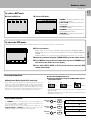
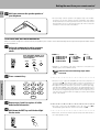
Compared to standard remote controls, the remote control supplied with this receiver has several
operation modes. These modes enable the remote control to perform on screen operations and control
other audio/video components. In order to effectively use the remote control it is important to read the
operating instructions and obtain a proper understanding of the remote control and how to switch its
operation modes (etc.).
Using the remote control without completely understanding its design and how to switch the operation
modes may result in incorrect operations.
Remote Control
About the supplied remote control . . .
B60-3009-10 CH (T) WS
98/12 11 10 9 8 7 6 5 4 3 2 1 97/12 11 10 9 8 7 6 5 4 3
Getting started
Caution : Read this page carefully to ensure safe operation.
KR-V999D (En/T)
2
Before applying the power
Units are designed for operation as follows.
U.K. and Europe ....................................................................... AC 230 V only
For the United Kingdom
Preparations
Factory fitted moulded mains plug
1.The mains plug contains a fuse. For replacement, use only a 13-Amp
ASTA-approved (BS1362) fuse.
2.The fuse cover must be refitted when replacing the fuse in the
moulded plug.
3.Do not cut off the mains plug from this equipment. If the plug fitted
is not suitable for the power points in your home or the cable is too
short to reach a power point, then obtain an appropriate safety
approved extension lead or adapter, or consult your dealer.
If nonetheless the mains plug is cut off, remove the fuse and dispose
of the plug immediately, to avoid a possible shock hazard by
inadvertent connection to the mains supply.
IMPORTANT
The wires in the mains lead are coloured in accordance with the
following code:
Blue : Neutral
Brown : Live
Do not connect those leads to the earth terminal of a three-pin
plug.
REQUIREMENT BY NEDERLAND GAZETTE
Batteries are supplied with this product. When
they empty, you should not throw away. Instead, hand them in as small chemical waste.
Safety precautions
Operations
WARNING :
TO PREVENT FIRE OR ELECTRIC SHOCK, DO NOT EXPOSE THIS APPLIANCE TO RAIN
OR MOISTURE.
CAUTION: TO REDUCE THE RISK OF ELECTRIC SHOCK, DO NOT REMOVE COVER (OR
BACK). NO USER-SERVICEABLE PARTS INSIDE, REFER SERVICING TO QUALIFIED SERVICE
PERSONNEL.
CAUTION
RISK OF ELECTRIC SHOCK
DO NOT OPEN
THE LIGHTNING FLASH WITH ARROWHEAD SYMBOL, WITHIN AN EQUILATERAL TRIANGLE, IS INTENDED TO ALERT THE
USER TO THE PRESENCE OF UNINSULATED “DANGEROUS VOLTAGE” WITHIN THE PRODUCT’S ENCLOSURE THAT MAY BE
OF SUFFICIENT MAGNITUDE TO CONSTITUTE A RISK OF ELECTRIC SHOCK TO PERSONS.
THE EXCLAMATION POINT WITHIN AN EQUILATERAL TRIANGLE IS INTENDED TO ALERT THE USER TO THE PRESENCE OF
IMPORTANT OPERATING AND MAINTENANCE (SERVICING) INSTRUCTIONS IN THE LITERATURE ACCOMPANYING THE
APPLIANCE.
Unpacking
Other
Unpack the unit carefully and make sure that all accessories are put aside so they will not be lost.
Examine the unit for any possibility of shipping damage. If your unit is damaged or fails to operate, notify your dealer immediately. If your
unit was shipped to you directly, notify the shipping company without delay. Only the consignee (the person or company receiving the
unit) can file a claim against the carrier for shipping damage.
We recommend that you retain the original carton and packing materials for use should you transport or ship the unit in the future.
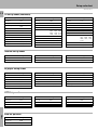
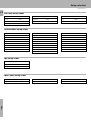
Accessories
FM indoor antenna (1)
Antenna adaptor (1)
Remote control unit (1)
AM loop antenna (1)
Batteries (R03/AAA) (4)
Loop antenna stand (1)
RF DEMODULATOR (1)
LAS
ER
DIS
C RF
PO
DEM
ODU
W
ER
LAT
OR
LO
DEM
CK
-99
9D
AC adaptor (1)
Power cord (1)
RCA pin cord (2)
KR-V999D (En/T)
Caution : Read the pages marked
Getting started
carefully to ensure safe operation.
2
Before applying the power ........................................................................................... 2
Safety precautions ........................................................................................................ 2
Unpacking ...................................................................................................................... 2
Special features
4
How to use this manual ................................................................................................ 5
Names and functions of parts
Setting up the system
Preparations
3
6
8
Connecting the antennas .............................................................................................. 8
Connecting audio components ..................................................................................... 9
Connecting video components ................................................................................... 10
Digital connections ...................................................................................................... 11
Connecting the system control ................................................................................... 12
Connecting the speakers ............................................................................................ 13
Making connections to another room (ROOM B) ...................................................... 15
Preparing the remote control ...................................................................................... 16
Preparing for surround sound
Preparations
Contents
17
Normal playback
20
Listening to a source component ............................................................................... 20
Adjusting the sound .................................................................................................... 21
Recording
23
Operations
Using the on-screen display ........................................................................................ 17
Surround setup ............................................................................................................ 18
Recording audio .......................................................................................................... 23
Recording video .......................................................................................................... 24
25
Tuning (non-RDS) radio stations ................................................................................. 25
Tuning radio stations by frequency (DIRECT tuning) ................................................. 26
Using RDS (Radio Data System) ................................................................................. 27
Using the DISPLAY key .............................................................................................. 27
Presetting RDS stations (RDS AUTO MEMORY) ....................................................... 28
Receiving preset RDS stations ................................................................................... 28
Presetting radio stations manually .............................................................................. 29
Receiving preset stations ........................................................................................... 29
Receiving preset stations in order (P.CALL) ............................................................... 29
Tuning by program type (PTY search) ......................................................................... 30
Reserving the desired information ............................................................................. 32
Operations
Ambience effects
34
Sound modes .............................................................................................................. 34
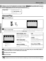
Surround play .............................................................................................................. 36
Getting the most from your remote control
Other
40
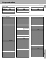
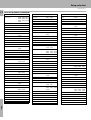
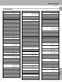
Registering setup codes for other components ......................................................... 40
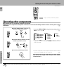
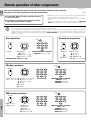
Operating other components ...................................................................................... 42
Changing (confirming) the operation mode ................................................................ 43
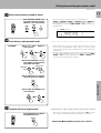
Preparing for automatic operations (MACRO play) .................................................... 44
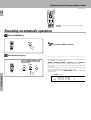
Executing an automatic operation .............................................................................. 46
Controlling the sound in another room (ROOM B) ..................................................... 47
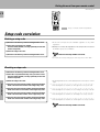
Setup code correlation ................................................................................................ 48
FutureSet upgrade option ........................................................................................... 49
Set up code chart
In case of difficulty
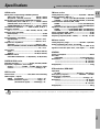
Specifications
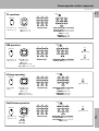
Remote operation of other components
51
57
59
60
Other
Remote Control
Remote Control
Listening to radio broadcasts
Special features
KR-V999D (En/T)
4
True home theater sound
This receiver incorporates a wide variety of surround modes to bring you maximum enjoyment from your video software. Select
a surround mode according to your equipment or the software you are going to play and enjoy!
›
Dolby Digital (AC-3)
Preparations
The DOLBY DIGITAL (AC-3) mode lets you enjoy full digital surround from software processed in the Dolby Digital (AC-3)
format. Dolby Digital (AC-3) provides up to 5.1 channels of independent digital audio for better sound quality and more
powerful presence than conventional Dolby Surround.
Dolby Pro Logic & Dolby 3 Stereo
This surround system reproduces theater-like surround sound from video software marked
.
The PRO LOGIC mode uses the built-in directivity enhancer circuit to control the Left, Center, Right and Surround channel
audio signals and reproduce a real sense of sound motion .
The 3 STEREO mode uses the directivity enhancer circuit to provide proper acoustic positioning and a real sense of sound
motion even when only the front and center speakers are used.
New DSP surround modes
The DSP (Digital Signal Processor) used for this receiver incorporates a variety of high quality adjustable sound fields, like
"ARENA", "JAZZ CLUB", "STADIUM", "CHURCH" and "THEATER", to add the “presence” associated with an arena, jazz club
or stadium (etc.) to the original signal. It is compatible with almost any kind of program source.
Operations
Universal IR (InfraRed) remote control
In addition to the basic receiver and OSD operations, the remote control supplied with this receiver can also operate almost
all of your remote controllable audio and video components. Just follow the simple setup procedure to register the
components you have connected.
‚
Dual IR emitters
This remote control has two IR emitters: one to send commands in a straight line over long distances, allowing you to control
the receiver and your other components from farther away; and one for wide dispersion of commands in a closer proximity,
for near-field operation even when the remote control is not pointed directly at the respective component.
^
MACRO play
The MACRO function lets you perform a series of operations automatically, like turning ON the power of the receiver and
connected components, switching the input selectors, and starting playback. (Be sure to register your components before
r
starting the macro set up procedure.)
Other
FutureSet, automatic update feature
This function lets you update the remote control so it can operate new components which do not appear in the setup code
o
list at the end of the manual. Therefore, the remote control will always be compatible.
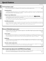
Easy surround setup and operation with OSD (On Screen Display)
This function takes advantage of your monitor TV to simplify the surround setup procedures so you can quickly and easily
match the surround processing to your speaker system, and your listening environment.
You can also use OSD during playback to customize the DSP surround modes, etc.
&
Special features
KR-V999D (En/T)
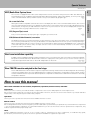
RDS (Radio Data System) tuner
5
The receiver is equipped with a RDS tuner that provides several convenient tuning functions: RDS Auto Memory, to
automatically preset up to 40 RDS stations broadcasting different programs; station name display, to show you the name
of the current broadcast station; and PTY search to let you tune stations by program type.
¶
Although most RDS compatible tuners and receiver's can display the name of the current broadcast station, this receiver
goes one step further by allowing you to display the station name, as well as any other text messages broadcast from the
current station, in large easy to read characters on the screen of your monitor TV. You can even display radio text from an
RDS station while enjoying a different source component!
¶°
PTY (Program TYpe) search
Lets you tune stations by specifying the type of program you want to hear.
Preparations
On screen Radio Text
º
EON (Enhanced Other Networks) reservation
Dual room installation capability
In addition to the standard "A" speaker output terminals for use in your main system, this receiver also incorporates separate
"B" speaker terminals and "Room B" RCA video and stereo output jacks. This system lets you use the remote control to
control and output audio and video to "Room B" independent of "Room A."
%u
Operations
The EON function lets you monitor information on other stations so you can receive traffic, news, or information programs
as soon as they are broadcast, even they are broadcast on a station different from the one you are currently listening to.
When the broadcast ends, the receiver returns to the original station. When listening to KENWOOD source components
connected with system control cords, the input selector on the receiver automatically switches to the tuner when a
program you desire is broadcast.
¤
New TRAITR transistor adopted in the final stage
How to use this manual
This manual is divided in to four sections, Preparations, Operations, Remote Control, and Other.
Remote Control
A new TRAITR transistor which features superior temperature tracking characteristics has been adopted in the final stage
of the power amplifier block. This new TRAITR transistor combines a temperature compensation resistor with an emitter
resistor and final transistor to provide ideal temperature compensation characteristics and minimize distortion caused by
temperature variations.
Preparations
Shows you how to connect your audio and video components to the receiver and prepare the surround processor.
We've tried to make setting up your system as easy as possible. However, since this receiver works with all of your audio and video
components, connecting the system can be fairly complex.
Remote Control
Shows you how to operate the various functions available from the remote control.
We've designed this remote control to integrate your entire audio/video system and let you operate all of your entertainment components
— your TV, VCR, LD player, CD player, etc. Remember that before you can use the remote control to operate these components, they
must be registered with a proper setup code.
Other
Includes additional information such as; a list of setup codes for registering your other components, a troubleshooting guide,
specifications, and a reference guide to the remote operations available for registered components.
Other
Operations
Shows you how to operate the various functions available from the receiver.
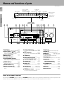
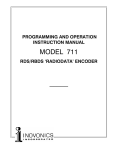
Names and functions of parts
KR-V999D (En/T)
6
Frequency display,
Input display,
Preset channel display,
Surround mode display
RDS indicators
SURROUND
indicator
AC-3
indicator
Band indicators
DSP indicator
MEMORY indicator
TA NEWS INFO.
RDS EON PTY
TP
SP. A
ROOM
A
B
B
*******;**
MEMORY
AC-3
FM
DSP
AUTO
3 STEREO
LOUDNESS
STEREO
S. DIRECT
TAPE 2
TUNED
SURROUND
AM
kHz
MHz
TUNED indicator
3 STEREO indicator
S.DIRECT indicator
Preparations
Speaker indicators
ROOM indicators
AUTO indicator
STEREO indicator
LOUDNESS indicator
TAPE 2
indicator
Display
1
2
3
4
5 6
8 9 0 !@
7
#
$
AUDIO−VIDEO SURROUND RECEIVER KR-V999D
BASS
TREBLE
FLAT
FLAT
2 CH
LEVEL
STANDBY DOWNMIX INDICATOR
1
ON/STANDBY
−10
+10
−10
+10
POWER
DIRECT
2
3
4
MEMORY
5
AUTO
6
7
8
9
0
PRO LOGIC
3 STEREO
STEREO
SOURCE DIRECT
DSP
DIMMER
LOUDNESS
+10/
PTY SEARCH
TUNING
BAND
DOLBY
DIGITAL
INPUT SELECTOR
VOLUME CONTROL
MUTE TAPE 2 MONITOR
DOWN
UP
-ON –OFF
AV AUX
PHONES
Operations
A
TRAITR
SPEAKERS
B
TA/NEWS/INFO
PTY
DISPLAY
thermally reactive advanced instantaneous transistor
Full Digital Decoding
S−VIDEO
%
^&
1 POWER key
)
Use to turn the main power ON/OFF.
2 ON/STANDBY (
) key
)
Use to switch the power ON/STANDBY
when the POWER is turned ON.
Other
3 Tone Control knobs
4 Numeric keys
5 STANDBY indicator
6 2 CH DOWNMIX indicator
¡
)
¡
™
0 DOLBY DIGITAL key
£¢ ∞§¶
›
Use to turn on the DOLBY DIGITAL (AC-3)
mode.
! PRO LOGIC key
›
Use to turn on the DOLBY PRO LOGIC
mode.
@ STEREO key
(
™
›
Use to turn on the DOLBY 3 STEREO
mode.
)
Use to select the input sources.
$ VOLUME CONTROL knob
% PHONES jack
)
™
Use for headphone listening.
^ DIRECT key
§
•ª
Use to store radio stations in the preset
memory.
* SPEAKERS A/B keys
∞
( AUTO key
Use to select the auto tuning mode.
∞
) BAND key
Use to select the broadcast band.
¡ RDS keys
™ TUNING keys
¶º¤
∞
£ DIMMER key
Use to adjust the brightness of the display.
¢ MUTE key
¡
Use to mute the sound.
∞ TAPE 2 MONITOR key
£
Use to monitor a recording.
Use to tune radio stations directly by numerical input.
& MEMORY key
•
Use to tune in radio broadcasts.
# INPUT SELECTOR knob
Lights when the level of the signal being
input is too high.
8 SOURCE DIRECT key
9 DOLBY 3 STEREO key
(
Use to cancel the surround mode.
Lights when an DOLBY DIGITAL (AC-3)
format signal is being downmixed to 2
channel stereo.
7 LEVEL indicator
*
VIDEO L - AUDIO - R
)u
§ LOUDNESS key
¡
Use to activate the frequency weighting
network.
¶ DSP key
fi
Use to turn on, or switch, the DSP mode.
• AV AUX jacks
0
Use to turn the speakers ON/OFF.
About the STANDBY indicator
This unit has a STANDBY indicator. When the STANDBY indicator is lit, the unit consumes a small amount of power to preserve the
memory. This is called STANDBY mode. This mode also lets you turn the power ON using the remote control.
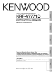
Names and functions of parts
KR-V999D (En/T)
7
1
POWER
MACRO
2
TV
8
P. CALL
4
0
AUDIO
VIDEO
!
@
Preparations
3
SHIFT
P. CALL
BAND
6
4
¢
7
GUIDE
TUNING/SKIP
MUTE
6
7
8
9
#
VOLUME
SUBWOOFER
LISTEN
MODE
FUNCTION
SHIFT
$
%
^
&
*
SOUND
SETUP
MENU
THEME
1
2
FAV
3
TV/SAT/VID
INFO
ALT AUD
4
5
6
+100
REPEAT
RANDOM
7
8
9
ROOM A
DISPLAY
ROOM B
+10
0
ENT
Operations
5
REC
w
Use to turn the receiver on and off.
Use in combination with the input selector
(AUDIO, VIDEO, or TV) keys and SHIFT key
to turn various components on and off.
2 MACRO key
r
Use in combination with the AUDIO,
VIDEO, or TV keys to execute a series of
commands automatically (MACRO PLAY).
3 VIDEO selector key
‚
Selects the video inputs (VIDEO 1, VIDEO
2, VIDEO 3, VIDEO 4, AV AUX) and sets the
remote to operate the component registered at the respective input.
4 Multi control keys
P
Use to operate the selected component
and to operate the on-screen display.
5 REC key
P
Use to operate the selected component.
6 TUNING/SKIP key
*P
Use during the setup procedure to specify
various settings. Use to operate the tuner
or selected component.
7 SUBWOOFER key
°
Use in combination with the VOLUME +/–
keys to adjust the volume of the subwoofer.
8 FUNCTION SHIFT key
P
Use in combination with the numeric keys
to execute alternate commands.
9 Numeric keys
P
Provide functions identical to those of the
original remote supplied with the component you are controlling.
To access the functions printed above the
keys, Press within 3 seconds of pressing
the FUNCTION SHIFT key. Function availability varies for each component.
0 SHIFT key
e
Use in combination with the AUDIO and
VIDEO keys to change the remote control
mode without changing the input selector
or in combination with the POWER key to
turn on and off components programmed
into the remote.
! TV selector key
‚
Sets the remote to operate a TV or cable
box (TV 1, TV 2, CABLE). This key does not
change the input selector on the receiver.
@ AUDIO selector key
‚
Selects the audio inputs (CD, TAPE1/MD.
TUNER, PHONO) and sets the remote to
operate the respective KENWOOD audio
component.
If you connect audio components from
KENWOOD and other makers to the
TAPE1/MD or CD jacks, you can set the
remote to operate these components by
registering the appropriate setup code at
the respective input.
# GUIDE key
P
Use to activate the OSD menu functions of
registered components.
$ VOLUME key
)
Use to adjust the receiver volume.
% MUTE key
¡
Use to temporarily mute the sound.
^ SOUND key
fl
Use to activate the Sound OSD and set the
remote to OSD control mode.
& LISTEN MODE key
°
Use to select the desired surround mode.
* SETUP key
*
Use to activate the Setup OSD and set the
remote to OSD control mode.
Other
1 POWER key
Remote Control
REMOTE CONTROL UNIT
RC-R0905
Setting up the system
KR-V999D (En/T)
8
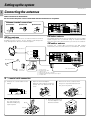
Connecting the antennas
Make connections as shown below.
Do not connect the power cord to a wall outlet until all connections are completed.
Antenna terminal connections
Preparations
2 Insert cord.
1 Push lever.
3 Return lever.
FM indoor antenna
AM loop antenna
The supplied loop antenna is for use indoors. Place it as far as
possible from the receiver, TV set, speaker cords and power
cord, and adjust the direction for best reception.
The supplied indoor antenna is for temporary use only. For stable
signal reception we recommend using an outdoor antenna.
Disconnect the indoor antenna when you connect one outdoors.
FM outdoor antenna
Lead the 75Ω coaxial cable connected to the FM outdoor
antenna into the room and connect it to the FM 75Ω terminal.
AM loop antenna
Operations
AM
GND
FM75Ω
ANTENNA
FM indoor antenna
1
2
3
4
5
6
Loosen screw.
Insert antenna cable
Tighten screw.
Plug securely into 75 Ω terminal.
Find the position that provides best reception.
Fix both ends.
FM outdoor antenna
75 Ω coaxial cable connection
Other
1 Arrange the coaxial cable as illustrated.
2 Open the antenna adaptor.
Open the claws with the fingers to
release the lock and pull out the
cover.
3 Remove the inner conductor from
the groove of pole A and insert it in
the groove of pole B.
Pole A
5
4
3 (mm)
RG-6(5C-2V) or RG-59(3C-2V)
Pole B
Claw
Ω
Band B
75
Band A
5 Close the cover and connect the adaptor to the
antenna terminal.
Ω
75 0Ω
30
4 Insert into the slit on
the clip. Fasten the
bands A and B,using
a pair of pliers.
Setting up the system
KR-V999D (En/T)
Connecting audio components
Microcomputer malfunction
If operation is not possible or an erroneous display appears, even
though all connections have been made properly, reset the
microcomputer referring to “In case of difficulty”.
U
Preparations
Make connections as shown below.
When connecting the related system components, be sure
to also refer to the instruction manuals supplied with the
components you are connecting.
Do not connect the power cord to a wall outlet until all
connections are completed.
9
SYSTEM CONTROL jacks
For SYSTEM CONTROL connections to KENWOOD components
@
SYSTEM
CONTROL
ƒ
SYSTEM CONTROL
cord
SL 16
SYSTEM CONTROL switch
XS 8
Shape of AC outlets
To AC wall outlet
U.K.
Ventilation fan
AUDIO
R
L
REC
PLAY
Cassette deck 2* or
graphic equalizer
REC
OUT
TAPE 2
MONITOR
PLAY
IN
REC
REC
OUT
PLAY
TAPE 1/MD
PLAY
IN
Operations
Except for U.K.
Cassette deck 1 or
MD recorder
CD
CD player
Other
PHONO
Ventilation fan
The ventilation fan runs during high-power reproduction. To
allow for proper ventilation, maintain a certain distance between the wall and the rear of the component.
Record player
Caution regarding placement
To maintain proper ventilation, be sure to leave a space around
the unit (from the largest outer dimensions, including projections) equal to, or greater than shown below:
Left and right panels: 10 cm, Rear panel: 10 cm, Top panel: 50 cm
Notes
* Do not connect a System Control cord to a cassette deck
connected to the TAPE 2 MONITOR jacks.
1. Connect all cords firmly. Loose connections may prevent proper sound transmission or produce noise.
2. Be sure to remove the power cord from the AC outlet before plugging or unplugging any connection cords. Plugging / unplugging connection
cords without disconnecting the power cord can cause malfunctions and may damage the unit.
3. Do not connect power cords from components whose power consumption is larger than what is indicated on the AC outlet at the rear of
this unit.
Setting up the system
KR-V999D (En/T)
10
Connecting video components
Make connections as shown below.
When connecting the related system components, be sure to also refer to the instruction manuals supplied with the
components you are connecting.
Do not connect the power cord to a wall outlet until all connections are completed.
Preparations
Video deck or video camera
About the S-VIDEO jacks
VIDEO
OUT
MONITOR
OUT
AUDIO
OUT
S-VIDEO cord
(Front Panel)
AV AUX
S-VIDEO
VIDEO
L−AUDIO−R
To AC wall outlet
Use the S-VIDEO jacks to make connections
to video components with S-VIDEO IN/OUT
jacks.
Operations
• If you use the S-VIDEO jacks to connect your
video playback components, be sure to use
the S-VIDEO jacks when connecting your
monitor and video recording components.
• When both S-VIDEO and normal video plugs
are connected to the MONITOR OUT jacks,
the receiver's on screen display is output
from the S-VIDEO jack only.
S-VIDEO
VIDEO
R
REC
OUT
REC
OUT
VIDEO 1
VIDEO 1
PLAY
IN
PLAY
IN
REC
OUT
REC
OUT
VIDEO 2
VIDEO 2
PLAY
IN
PLAY
IN
VIDEO 3
PLAY IN
VIDEO 3
PLAY IN
VIDEO 4
PLAY IN
VIDEO 4
PLAY IN
L
AUDIO
MONITOR
OUT
Other
S-VIDEO jacks
OUT
OUT
Yellow RCA
pin cord
VIDEO IN
LD player
OUT
TV/CABLE tuner
OUT
Monitor TV
OUT
OUT
IN
IN
Video deck 2
OUT
OUT
Video inputs and outputs
(Yellow RCA pin cords)
IN
Video deck 1
IN
Audio inputs and outputs
(Red and white RCA pin cords)
Setting up the system
KR-V999D (En/T)
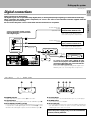
Digital connections
11
OPTICAL DIGITAL OUT
(AUDIO)
Optical fiber cable
Connect components capable of outputting Dolby Digital (AC-3) or standard PCM
format digital signals.
Connect the video signal and analog
audio signals to the VIDEO 2 jacks.
(See "Connecting video components".)
VIDEO2
(OPTICAL)
COAXIAL DIGITAL OUT
(AUDIO)
RCA pin cord
VIDEO3
AC-3
DIGITAL IN
Component with an AC-3 (or
PCM) COAXIAL DIGITAL OUT
Connect the video signal and analog
audio signals to the VIDEO 3 jacks.
(See "Connecting video components".)
RCA pin cord
VIDEO4
Component with an AC-3 (or
PCM) OPTICAL DIGITAL OUT
Preparations
Make connections as shown below.
The digital in jacks can accept either Dolby Digital (AC-3) or PCM signals (the input signal type is detected automatically).
When connecting the related system components, be sure to also refer to the instruction manuals supplied with the
components you are connecting.
Do not connect the power cord to a wall outlet until all connections are completed.
AC-3 DIGITAL
OUTPUT
AC-3 RF
INPUT
DC IN
12V
OFF ON
Operations
@ #
AC-3 RF OUT
(AUDIO)
RCA pin cord
LASER DISC RF DEMODULATOR DEM-999D
POWER
LOCK
AC-3 RF Demodulator DEM-999D
1
2
3
4 5 6
AC-3 DIGITAL
OUTPUT
POWER
DC IN
12V
AC-3 RF
INPUT
OFF ON
LASER DISC RF DEMODULATOR DEM-999D
@ #
LOCK
EXTERNAL DC SUPPLY DC 12V
1 POWER indicator
Lights (red) when the power switch (5) is set to ON .
2 LOCK indicator
Lights when an AC-3 RF signal is input to the AC-3 RF INPUT jack (4).
3 AC-3 DIGITAL OUTPUT (coaxial)
Connect this jack to the coaxial AC-3 DIGITAL IN jack on your receiver.
It outputs AC-3 coaxial digital signals when the POWER (5) is set to
ON and an AC-3 RF signal is input to the AC-3 RF INPUT jack (4).
4 AC-3 RF INPUT
Connect this jack to the AC-3 RF OUTPUT jack on your LD player.
5 POWER switch
Use to switch the power ON/OFF.
6 DC IN (12V) jack
Connect this jack and inlet power cord to the AC adaptor supplied with
your demodulator. Connect the power cord to a wall outlet after
completing all of the other connections.
Place the power supply away from the demodulator,
receiver, and any antennas.
Other
To connect an LD player with a DIGITAL RF OUT.
Connect the LD player to the KENWOOD RF digital
demodulator (DEM-999D). Then connect the demodulator to the VIDEO 4 DIGITAL IN.
Connect the video signal and analog audio signals to the
VIDEO 4 jacks. (See "Connecting video components".)
Setting up the system
KR-V999D (En/T)
12
Connecting the system control
Connecting system control cords after connecting a KENWOOD audio component system lets you take advantage of
convenient system control operations.
There are two KENWOOD system control modes. Make connections according to the groups of terminal symbols shown
below.
Preparations
ƒ Mode : lets you combine f, ƒ, and F terminals
Mode : for
terminals only
This unit is compatible with both [XS8] and [SL16] modes. It comes from the factory set to the [SL16] mode. To switch to the [XS8] mode, follow
the instructions in “SWITCHING FROM [SL16] TO [XS8]” below.
EXAMPLE: [XS8] mode connections
EXAMPLE: [SL16] mode connections
The underlined portion represents the setting of the system control mode.
The underlined portion represents the setting of the system control mode.
[SL16] [XS8]
Receiver
[SL16] [XS8]
Receiver
[SL16]
MD recorder
[SL16]
MD recorder
[SL16] [XS] [XS8] [XR]
Cassette deck
[SL16] [XS] [XS8] [XR]
Cassette deck
[SL16] [XS] [XS8]
CD player
[SL16] [XS] [XS8]
CD player
[XS]
Record player
[XS]
Record player
SYSTEM
CONTROL
cord
SYSTEM
CONTROL
cord
Operations
• In order to take advantage of the system control operations, the components must be connected to the correct jacks. To use a CD player it must
be connected to the CD jacks. To use a cassette deck (or MD recorder) it must be connected to the TAPE1/MD jacks. When using more than one
CD player (etc.) only the one connected to the specified jacks may be connected for system control.
• Some CD players and cassette decks are not compatible with the [SL16] system control mode. Be sure to use the [XS8] system control mode
when making system connections with equipment that is not [SL16] compatible.
• Some MD players are not system control compatible. You cannot make system control connections to this kind of equipment.
Notes
1. [SL16] equipment cannot be combined with [XR], [XS], and [XS8] equipment for system operations. If your
equipment consists of this kind of combination, please do not connect any system control cords. Even without
system control cords, normal operations can be carried out without effecting performance.
2. Do not connect system control cords to any components other than those specified by KENWOOD. It may
cause a malfunction and damage your equipment.
3. Be sure the system control plugs are inserted all the way in to the system control terminals.
Other
SYSTEM CONTROL OPERATIONS
SWITCHING FROM [SL16] TO [XS8]
Remote Control
Lets you operate this unit with the system remote supplied with the
receiver.
You can easily change the system control mode by adjusting the
position of the SYSTEM CONTROL switch on the rear panel.
Do this operation after completing all connections.
Automatic Operation (except [XR] equipment)
When you start playback from a source component, the input selector
on this unit switches to that component automatically.
Synchronized Recording (except [XR] equipment)
Lets you synchronize recording with the start of playback when
recording from CD, MD or analog discs.
SL 16
XS 8
For [SL16]
For [XS8]
• This operation will not effect items stored in the memory.
• After switching the system control mode, turn the power off and
then on once to confirm the new setting.
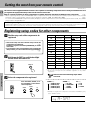
Registering setup codes for KENWOOD audio components
• Once you finish making the system connections, be sure to register the appropriate setup code for each component.
‚
• If you own remote controllable KENWOOD audio components that are not compatible with system control (or cannot be combined with your other
system control components), registering the setup code enables you to control those components using the remote control supplied with this
unit (without connecting system control cords). To register setup codes for your remote controllable KENWOOD audio components, see
"Registering setup codes for other components".
‚
Setting up the system
KR-V999D (En/T)
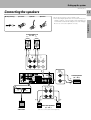
Connecting the speakers
2 Loosen.
3 Insert.
4 Secure.
• Never short circuit the + and – speaker cords.
• If the left and right speakers are connected inversely or the
speaker cords are connected with reversed polarity, the
sound will be unnatural with ambiguous acoustic imaging.
Be sure to connect the speakers correctly.
Preparations
1 Strip coating.
13
Front Speakers A
(4Ω~16Ω)
Left
Right
ª
ª
·
Operations
·
FRONT SPEAKERS (4−16 Ω)
A
R
B
L
R
L
+
−
CENTER
SPEAKER
(4−16Ω) C
ª
−
·
SURROUND SPEAKERS
R (4−16Ω) L
PRE
OUT
SURROUND
+
SUB WOOFER
−
ª
Powered
subwoofer
·
Right
·
Surround Speakers
(4Ω~16Ω)
ª
Left
(Be sure to connect both surround speakers)
Center Speaker
(4Ω~16Ω)
Other
+
Setting up the system
KR-V999D (En/T)
14
PRE OUT connections
This receiver has additional preout jacks. These can be used for various purposes, but will need to be connected to an external power
amplifier as shown in the example below. Connecting a speaker cord directly to a PRE OUT jack will not produce any sound from the
speaker.
Preparations
Be sure to set the SPEAKERS A key to the ON position when using the PRE OUT jacks in Room A.
No sound is output from the SUBWOOFER jack when the SPEAKERS A key is set to the OFF position.
Front Speakers
Power amp
FRONT
CENTER
PRE
OUT
Center Speaker
Operations
Power amp
SURROUND
Powered
Subwoofer
SUB WOOFER
Surround speakers
Power amp
Other
Setting up the system
KR-V999D (En/T)
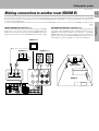
Making connections to another room (ROOM B)
15
FRONT SPEAKERS B connections (1):
These connections allow you to connect the speakers in ROOM
B directly to the receiver without using an additional power
amplifier. The sound from the main system (ROOM A) automatically switches to stereo when SPEAKERS B are turned on.u
SECOND ROOM PRE OUT connections (2):
Use these connections if you want to enjoy surround sound from
your main system (ROOM A) while outputting another source to
ROOM B. Connecting a speaker cord directly to a SECOND
ROOM PRE OUT jack will not produce any sound from the
speaker. Connect the SECOND ROOM PRE OUT jacks to powered speakers or power amplifiers connected to speakers.
Preparations
The following connections allow you to connect your main system to a monitor TV and speaker system located in another area (ROOM
B). The monitor TV can be connected directly to the SECOND ROOM PRE OUT VIDEO jack. To connect the speakers, use either of the
connections described below.
To select the input and adjust the volume (etc.) for your other area (ROOM B), set the remote control to the ROOM B operation mode.
u
Monitor TV
Speakers (2)
Power amp
·
ª
ª
·
ROOM A
(Main System)
Operations
Speakers (1)
FRONT SPEAKERS (4−16 Ω)
A
VIDEO
R AUDIO L
B
L
R
L
+
SECOND ROOM PRE OUT
ROOM B
−
Other
R
Setting up the system
KR-V999D (En/T)
16
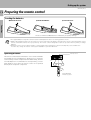
Preparing the remote control
Loading the batteries
1 Remove the cover.
3 Close the cover.
2 Insert the batteries.
Preparations
• Insert four AAA-size (LR03) batteries as indicated by the polarity markings.
1. The supplied batteries may have shorter lives than ordinary batteries due to use during operation checks.
2. Replace all four batteries with new ones when you notice a shortening of the distance from which the remote control will operate or if the
Notes
remote control blinks 5 times when you push a key. The remote control is designed to retain set up codes in memory while you change
batteries.
3. Placing the remote sensor in direct sunlight, or in direct light from a high frequency fluorescent lamp may cause a malfunction.
In such a case, change the location of the system installation to prevent malfunction.
Operations
Operating distance
This remote control has two IR emitters: one to send commands
in a straight line over long distances, allowing you to control the
receiver and your other components from farther away; and one
for wide dispersion of commands in a closer proximity, for nearfield operation even when the remote control is not pointed
directly at the respective component.
Remote sensor
6m
10 m
30˚
30˚
Model: RC-R0905
Infrared ray system
Other
Preparing for surround sound
KR-V999D (En/T)
This receiver incorporates an on screen display (OSD) feature to simplify the surround setup procedure by providing
large easy to read graphic information.
The section below shows you how to operate the on-screen
display. Read this first before going on to the surround setup
procedures on the following pages.
POWER
MACRO
17
SHIFT
AUDIO
VIDEO
TV
8
P. CALL
P. CALL
4
BAND
6
¢
7
REC
GUIDE
TUNING/SKIP
VOLUME
MUTE
SUBWOOFER
• Set the POWER key to ON.
• Set the ON/STANDBY key to ON.
• Turn on your monitor TV.
LISTEN
MODE
FUNCTION
SHIFT
MENU
SOUND
SETUP
THEME
FAV
1
2
3
TV/SAT/VID
INFO
ALT AUD
4
5
6
+100
REPEAT
RANDOM
7
8
9
ROOM A
DISPLAY
ROOM B
+10
0
ENT
Keys or controls used in this operation.
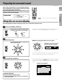
Using the on-screen display
On-screen operations consist of moving the arrow icon to select items from the screen.
1 Press the SOUND or SETUP key.
Pressing either the SOUND or SETUP key automatically activates the on-screen display
SOUND
• The remote control automatically switches to OSD remote control
mode when an on-screen display appears in your monitor TV.
SETUP
2 Move the pointer.
EXAMPLE: moving the pointer to an icon at right.
It can be moved in 8 directions, depending on
how you press the keys
8
P. CALL
P. CALL
EXAMPLE: when the pointer is
moved to the DSP command.
BAND
P. CALL
8
4
6
¢
3 STEREO
P. CALL
BAND
4
6
¢
DSP
7
Press the > key.
7
• If no icons are located in the direction you pressed, the pointer may
move in a different direction to locate the nearest object.
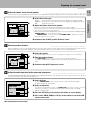
3 Press the item you desire.
P. CALL
8
• To confirm an item, press the BAND (6) key located in the center of
the remote control after moving the pointer to the item you want to
select.
P. CALL
The DSP screen appears.
BAND
4
6
¢
WALL = MEDIUM
ROOMSIZE = MEDIUM EFFECT LEVEL = 3
7
MAIN
To quit the OSD mode:
1 Press the SOUND or SETUP key again.
2 Press either the VIDEO, AUDIO, or TV key to cancel the OSD
remote control mode.
ARENA
JAZZ CLUB
STADIUM CHURCH THEATER
Preparations
Preparations
Preparing for surround sound
KR-V999D (En/T)
18
Surround set up
To obtain the best possible enjoyment from the receiver's various surround modes, be sure to complete the surround set up
as shown below.
1 Speaker placement.
Preparations
Center speaker
Subwoofer
Front speaker
Listening position
Front speakers : Place to the front left and right of the listening position. Front
speakers are required for all surround modes.
Center speaker : Place front and center. This speaker stabilizes the sound image
and helps recreate sound motion. Be sure to connect a center speaker when
using the Dolby 3 Stereo mode.
Surround speakers : Place to the direct left and right, or slightly behind, the
listening position at even heights, approximately 1 meter above the ears of
the listeners. These speakers recreate sound motion and atmosphere.
Required for surround playback.
Subwoofer : Reproduces powerful deep bass sounds.
• Although the ideal surround system consists of all the speakers listed above, if you don't
have a center speaker or a subwoofer, you can divide those signals between the available
speakers in the following steps to obtain the best possible surround reproduction from the
speakers you have available.
Surround speaker
2 Go to the SP.SLCT (speaker select) page of the SET UP screen.
MAIN
SET UP
SP.SLCT
SP.LVL
SP.DIST
SETUP
L SW C
R
LS
• Pressing the MAIN icon lets you access
the main sound menu.
fl
IN LVL
SPEAKER
SELECTION
SW : ON
LR : LRG
C : LRG
RS S : LRG
3 Select the speakers and enter the speaker distance.
1 Specify the type of speakers you connected to the receiver.
1
2
3
4
MAIN
SET UP
SP.SLCT
SP.LVL
L SW C
LS
SP.DIST
R
IN LVL
2
SW : Subwoofer
ON: Select when using a subwoofer.
OFF: Select when not using a subwoofer.
SPEAKER
SELECTION
SW : ON
LR : LRG
C : LRG
RS S : LRG
Move the pointer downward (icon turns blue).
Use the TUNING/SKIP keys to specify the setting you desire.
Press the BAND (6) key to confirm the setting (icon turns yellow).
Repeat steps 2 and 3 to specify a setting for each speaker type.
• Be sure to specify settings for each speaker type before continuing to the next
screen.
1
L R : Front speakers (left and right)
SML (small): Select when using a relatively small front speakers.
LRG (large): Select when using a relatively large front speakers.
C : Center speaker
SML (small): Select when using a relatively small center speaker.
LRG (large): Select when using a relatively large center speaker.
OFF: Select when not using a center speaker.
S : Surround speakers (left and right)
SML (small): Select when using a relatively small surround speaker.
LRG (large): Select when using a relatively large surround speaker.
OFF: Select when not using surround speakers.
2 Continue to the SP.LVL (speaker level) screen.
Preparing for surround sound
KR-V999D (En/T)
4 Adjust the volume levels of each speaker.
19
Listen to the test tone and adjust the volume level of each speaker so that they all produce the test tone at the same volume level.
1 Select the test tone type.
SP.SLCT
SP.LVL
SP.DIST
3
IN LVL
2 Adjust the Volume level of each speaker.
SPEAKER
LEVEL
1 Listen to the test tone and select the speaker you want to adjust.
• The selected speaker icon turns blue and the speaker name and level appear (at the bottom of
the screen) to show that it can be adjusted.
TEST TONE
L
=
AUTO
: The test tone switches between each speaker in regular intervals.
MANUAL : The test tone only comes from the selected speaker (displayed in blue).
OFF
: Stops the test tone.
AUTO
MANUAL
OFF
1
0dB
2
2 Listen to the test tone and adjust the volume level of the speaker (± 10 dB) using the
TUNING/SKIP keys on the remote control.
TUNING/SKIP – : Lowers the volume TUNING/SKIP + : Raises the volume
• Adjust the subwoofer as you desire.
3 Continue to the SP.DIST (speaker distance) screen.
5 Enter the speaker distance.
Enter the distance from your listening position to the front (left or right), center, and rear (left or right) speakers. If both front (or
rear) speakers are not the same distance from the listening position, enter the distance to the closest speaker.
SP.SLCT
1 Select the speaker.
MAIN
SET UP
SP.LVL
SP.DIST
The speaker name turns blue. An arrow icon appears to indicate the selected speaker.
3
IN LVL
2 Enter the speaker distance.
Use TUNING/SKIP on the remote control to select the appropriate distance.
The distance is adjustable from 0.0meters (0 feet) to 9.0meters (30 feet) in 0.3meter (1 foot)
steps.
SPEAKER
DISTANCE
FRONT
CENTER
SURR.
1
3 Continue to the IN LVL (input level) screen.
10ft 3. 0m
6 Adjust the audio input level of the connected components.
The LEVEL INDICATOR lights during playback if the signal being input from an analog source is too large. If this occurs, use this
screen to attenuate the input level for that source.
1 Select the input.
MAIN
SET UP
SP.SLCT
SP.LVL
SP.DIST
1 Use TUNING/SKIP on the remote control to select the desired input.
2 Move the pointer downward.
IN LVL
2 Select an input level.
INPUT LEVEL
SELECTOR: TUNER
LEVEL
: 0dB
1
2
The input level is adjustable in 3 levels. Use TUNING/SKIP on the remote control to select the
smallest level required to extinguish the LEVEL INDICATOR (normally, set to 0 dB).
0 dB Ô –3 dB Ô –6 dB
3 Press the SETUP key on the remote to turn off the on-screen display.
4 Press either VIDEO, AUDIO, or TV key on the remote to cancel the OSD
remote control mode.
This completes the surround setup.
Preparations
MAIN
SET UP
Normal playback
KR-V999D (En/T)
POWER
2 0 Preparations
MACRO
• Turn on the power to the related components.
• Set the POWER key to the ON position.
SHIFT
AUDIO
VIDEO
TV
8
P. CALL
AUDIO−VIDEO SURROUND RECEIVER KR-V999D
P. CALL
4
BAND
6
¢
7
REC
BASS
FLAT
GUIDE
TREBLE
FLAT
2-CH
LEVEL
STANDBY DOWNMIX INDICATOR
1
TUNING/SKIP
2
3
4
5
6
7
8
9
0
DOLBY
DIGITAL
PRO LOGIC
3 STEREO
STEREO
SOURCE DIRECT
DSP
DIMMER
LOUDNESS
INPUT SELECTOR
VOLUME CONTROL
+10/
PTY SEARCH
VOLUME
ON/STANDBY
MUTE
−10
+10
−10
+10
DIRECT
MEMORY
AUTO
TUNING
BAND
MUTE TAPE 2 MONITOR
POWER
POWER
DOWN
-ON
SUBWOOFER
LISTEN
MODE
UP
–OFF
AV AUX
PHONES
SOUND
A
TRAITR
SPEAKERS
B
TA/NEWS/INFO.
PTY
DISPLAY
thermally reactive advanced instantaneous transistor
S−VIDEO
FUNCTION
SHIFT
-ON –OFF
MENU
FAV
2
3
INFO
ALT AUD
4
+100
VIDEO L - AUDIO - R
SETUP
THEME
1
TV/SAT/VID
5
6
REPEAT
RANDOM
7
8
9
ROOM A
DISPLAY
ROOM B
+10
0
ENT
Keys or controls used in this operation.
Listening to a source component
1 Turn on the receiver.
ON/STANDBY
Operations
2 Set SPEAKERS A to on.
A
SP.
A
B
ROOM
A
B
SPEAKERS
• Surround modes cannot be activated when both SPEAKERS A and
SPEAKERS B are set to ON. For details on the SPEAKERS B button,
see "Controlling the sound in another room (ROOM B)".
u
• Be sure to set the SPEAKERS A key to the ON position when using the
PRE OUT jacks in Room A. No sound is output from the SUBWOOFER
jack when the SPEAKERS A key is set to the OFF position.
B
A-PHONO
The input sources change as shown below:
1
2
3
4
5
6
7
8
9
The speaker A indicator should be lit.
3 Select the source you desire.
INPUT SELECTOR
TUNER (Frequency display)
"PHONO"("PHONO"*)
"VIDEO1" ("SAT"*)
"VIDEO2" ("LD"*)
"VIDEO3" ("VCR"*)
"VIDEO4" ("DSS"*)
"AV AUX"
"CD" ("CD"*)
"TAPE1/MD" ("TAPE"*)
* Once setup codes are registered in the remote control, the input name
display changes according to the name of the registered component.
Example: if you register a VCR at the VIDEO 1 jacks, "VCR1" appears
instead of "VIDEO 1".
‚
4 Start playback from the selected source.
5 Adjust the volume.
• Both the default input name and the component type (i.e., " VIDEO1
'VCR1' ") are shown in the on screen display when the OSD mode is
set to ON.
°
• When using the remote control after initial setup, any inputs that have
not been registered with a setup code are deleted from the cyclic list
(except for the "AV AUX" VIDEO input).
w
• The INPUT SELECTOR on the front panel of the receiver always cycles
through all inputs.
VOLUME CONTROL
Volume display
DOWN
Decrease volume
UP
SP. A
Increase volume
ROOM A
V-A -6) dB
Normal playback
KR-V999D (En/T)
POWER
To adjust the balance
MACRO
SHIFT
21
AUDIO
VIDEO
(
Use the test tone feature.
TV
8
P. CALL
AUDIO−VIDEO SURROUND RECEIVER KR-V999D
P. CALL
BAND
6
4
¢
7
REC
BASS
FLAT
GUIDE
TREBLE
FLAT
2-CH
LEVEL
STANDBY DOWNMIX INDICATOR
1
TUNING/SKIP
2
3
4
5
6
7
8
9
0
DOLBY
DIGITAL
PRO LOGIC
3 STEREO
STEREO
SOURCE DIRECT
DSP
DIMMER
LOUDNESS
INPUT SELECTOR
VOLUME CONTROL
+10/
PTY SEARCH
VOLUME
ON/STANDBY
MUTE
−10
+10
−10
+10
DIRECT
MEMORY
AUTO
TUNING
BAND
MUTE TAPE 2 MONITOR
POWER
DOWN
-ON
SUBWOOFER
LISTEN
MODE
UP
–OFF
AV AUX
PHONES
SOUND
A
TRAITR
SPEAKERS
B
TA/NEWS/INFO.
PTY
DISPLAY
thermally reactive advanced instantaneous transistor
S−VIDEO
FUNCTION
SHIFT
MENU
FAV
2
3
INFO
ALT AUD
4
+100
VIDEO L - AUDIO - R
SETUP
THEME
1
TV/SAT/VID
5
6
REPEAT
RANDOM
7
8
9
ROOM A
DISPLAY
ROOM B
+10
0
ENT
Keys or controls used in this operation.
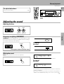
Adjusting the sound
Adjusting the tone
BASS
TREBLE
FLAT
+10
Adjusts low
frequencies
−10
+10
Adjusts high
frequencies
Frequency weighting (LOUDNESS)
LOUDNESS lets you emphasize the sound of frequencies that
are difficult to hear. The frequency emphasis varies according to
the volume at which you are listening.
LOUDNESS
AC-3
LOUDNESS
To cancel
Press again.
AC-3
Press again to return to previous sound.
Goes out
Muting the sound
MUTE lets you mute the sound of the speakers.
SP.
A
B
ROOM
A
B
MUTE A
Blinks when muting the sound in ROOM A
MUTE
To cancel
Press again.
SP.
A
B
ROOM
A
B
A-CD
• The mute button on the receiver allows you to mute the sound from the
speakers in ROOM A.
• The remote control lets you mute the sound from the speakers in
ROOM A and/or ROOM B depending on the current control mode.
u
Operations
−10
FLAT
Normal playback
KR-V999D (En/T)
POWER
MACRO
22
SHIFT
AUDIO
VIDEO
TV
8
P. CALL
AUDIO−VIDEO SURROUND RECEIVER KR-V999D
P. CALL
4
BAND
6
DOLBY
DIGITAL
¢
3 STEREO
7
REC
BASS
FLAT
GUIDE
TREBLE
FLAT
2-CH
LEVEL
STANDBY DOWNMIX INDICATOR
1
TUNING/SKIP
2
3
4
5
6
7
8
9
0
PRO LOGIC
STEREO
SOURCE DIRECT
DSP
DIMMER
LOUDNESS
INPUT SELECTOR
VOLUME CONTROL
+10/
PTY SEARCH
VOLUME
ON/STANDBY
MUTE
−10
+10
−10
+10
DIRECT
MEMORY
AUTO
TUNING
BAND
MUTE TAPE 2 MONITOR
POWER
DOWN
-ON
SUBWOOFER
LISTEN
MODE
UP
–OFF
AV AUX
PHONES
SOUND
A
TRAITR
SPEAKERS
B
TA/NEWS/INFO.
PTY
DISPLAY
thermally reactive advanced instantaneous transistor
S−VIDEO
FUNCTION
SHIFT
MENU
VIDEO L - AUDIO - R
SETUP
THEME
FAV
1
2
3
TV/SAT/VID
INFO
ALT AUD
4
5
6
+100
REPEAT
RANDOM
7
8
9
ROOM A
DISPLAY
ROOM B
+10
0
ENT
Keys or controls used in this operation.
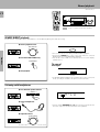
SOURCE DIRECT playback
Use this function to pass the source material direct to the amplifier, bypassing any audio processing.
1 Select a playback source.
AC-3
INPUT SELECTOR
S. DIRECT
Operations
2 Press the SOURCE DIRECT key.
• Tone controls do not work during SOURCE DIRECT playback.
• Pressing the STEREO key or any of the keys related to surround
playback will cancel SOURCE DIRECT playback.
• You can also select S.DIR (source direct) from the on-screen display
(SOUND menu).
SOURCE DIRECT
To cancel
Press again.
AC-3
3 Start playback .
Goes out
• If SOURCE DIRECT playback was activated when using a surround
mode, cancelling it reactivates the previous surround mode.
Listening with headphones
1 Turn OFF both speaker switches.
A
SPEAKERS
B
SP.
A
B
ROOM
A
B
A-CD
Make sure the SPEAKERS indicators are turned off.
2 Connect headphones.
PHONES
• Turning off both SPEAKERS A and B when using a surround mode will
cancel the respective mode and activate stereo playback.
3 Adjust the volume.
VOLUME CONTROL
DOWN
Decrease volume
UP
Increase volume
Recording
KR-V999D (En/T)
POWER
MACRO
SHIFT
23
AUDIO
VIDEO
TV
8
P. CALL
AUDIO−VIDEO SURROUND RECEIVER KR-V999D
P. CALL
4
BAND
6
¢
7
REC
BASS
FLAT
GUIDE
TREBLE
FLAT
2-CH
LEVEL
STANDBY DOWNMIX INDICATOR
1
TUNING/SKIP
2
3
4
5
6
7
8
9
0
DOLBY
DIGITAL
PRO LOGIC
3 STEREO
STEREO
SOURCE DIRECT
DSP
DIMMER
LOUDNESS
INPUT SELECTOR
VOLUME CONTROL
+10/
PTY SEARCH
VOLUME
ON/STANDBY
MUTE
−10
+10
−10
+10
DIRECT
MEMORY
AUTO
TUNING
BAND
MUTE TAPE 2 MONITOR
POWER
DOWN
-ON
SUBWOOFER
LISTEN
MODE
UP
–OFF
AV AUX
PHONES
SOUND
A
TRAITR
SPEAKERS
B
TA/NEWS/INFO.
PTY
DISPLAY
thermally reactive advanced instantaneous transistor
S−VIDEO
FUNCTION
SHIFT
MENU
FAV
2
3
INFO
ALT AUD
4
+100
VIDEO L - AUDIO - R
SETUP
THEME
1
TV/SAT/VID
5
6
REPEAT
RANDOM
7
8
9
ROOM A
DISPLAY
ROOM B
+10
0
ENT
Keys or controls used in this operation.
Recording audio
Recording a music source
1 Select the source you want to record.
INPUT SELECTOR
• To record a digital source, connected to the VIDEO 2, 3, or 4 jacks, turn
the INPUT SELECTOR to select the appropriate component, then
press the STEREO key.
When making a digital recording, operations other than volume adjustment may cause the sound to clip during recording.
Select a source other than TAPE 1
Operations
2 Set the cassette deck to record.
3 Start playback, then start recording.
Dubbing tapes (TAPE 2 = TAPE 1)
1 Press TAPE 2 MONITOR.
TAPE2 MONITOR
AC-3
TAPE 2
2 Set the input selector to a source other
than TAPE 1.
Lights
INPUT SELECTOR
3 Start playback from TAPE 2, then start
recording on TAPE 1.
• When copying with a double cassette deck, refer to the operating
instructions supplied with the deck.
Dubbing tapes (TAPE 1 = TAPE 2)
1 Set the INPUT SELECTOR to TAPE 1.
2 Start playback from TAPE 1, then start recording on TAPE 2.
TAPE 2 MONITOR function
You can connect either a cassette deck or a graphic equalizer to the receiver's TAPE 2 jacks. If you connect a graphic equalizer, the TAPE
2 MONITOR key should be turned ON. If you connect a 3-head cassette deck, you can compare the source sound to the sound being
recorded while recording. Press the TAPE 2 MONITOR key to switch between the recorded sound to the source sound. For further
details, refer to the operating instructions supplied with the component you connected.
The TAPE 2 MONITOR function cannot be used when making digital recordings.
Recording
KR-V999D (En/T)
POWER
MACRO
24
SHIFT
AUDIO
VIDEO
TV
8
P. CALL
AUDIO−VIDEO SURROUND RECEIVER KR-V999D
P. CALL
4
BAND
6
¢
7
REC
BASS
FLAT
GUIDE
TREBLE
FLAT
2-CH
LEVEL
STANDBY DOWNMIX INDICATOR
1
TUNING/SKIP
2
3
4
5
6
7
8
9
0
DOLBY
DIGITAL
PRO LOGIC
3 STEREO
STEREO
SOURCE DIRECT
DSP
DIMMER
LOUDNESS
INPUT SELECTOR
VOLUME CONTROL
+10/
PTY SEARCH
VOLUME
ON/STANDBY
MUTE
−10
+10
−10
+10
DIRECT
MEMORY
AUTO
TUNING
BAND
MUTE TAPE 2 MONITOR
POWER
DOWN
-ON
SUBWOOFER
LISTEN
MODE
UP
–OFF
AV AUX
PHONES
SOUND
A
TRAITR
SPEAKERS
B
TA/NEWS/INFO.
PTY
DISPLAY
thermally reactive advanced instantaneous transistor
S−VIDEO
FUNCTION
SHIFT
MENU
FAV
2
3
INFO
ALT AUD
4
+100
VIDEO L - AUDIO - R
SETUP
THEME
1
TV/SAT/VID
5
6
REPEAT
RANDOM
7
8
9
ROOM A
DISPLAY
ROOM B
+10
0
ENT
Keys or controls used in this operation.
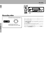
Recording video
1 Select the source you want to record.
INPUT SELECTOR
2 Set the video deck to record.
Operations
3 Start playback, then start recording.
• When recording to a VCR connected to the VIDEO1 jacks, select a
source other than VIDEO1.
• When recording to a VCR connected to the VIDEO2 jacks, select a
source other than VIDEO2.
• To record a digital source, connected to the VIDEO 2, 3, or 4 jacks, turn
the INPUT SELECTOR to select the appropriate copmponent, then
press the STEREO key.
When making a digital recording, operations other than volume adjustment may cause the sound to clip during recording.
• The AV AUX jacks on the front panel provide a convenient way to
connect a video camera (playback only).
• When recording a Dolby Digital (AC-3) source, press the STEREO key
to light the "2 CH DOWNMIX" indicator.
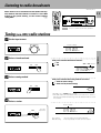
Listening to radio broadcasts
KR-V999D (En/T)
Radio stations can be classified into RDS (Radio Data System) stations and other stations. To listen to or store RDS
stations in the preset memory, see the section entitled,
"Using RDS".
¶
POWER
MACRO
SHIFT
25
AUDIO
VIDEO
TV
8
P. CALL
AUDIO−VIDEO SURROUND RECEIVER KR-V999D
P. CALL
4
BAND
6
¢
7
REC
BASS
FLAT
GUIDE
TREBLE
FLAT
2-CH
LEVEL
STANDBY DOWNMIX INDICATOR
1
TUNING/SKIP
2
3
4
5
6
7
8
9
0
DOLBY
DIGITAL
PRO LOGIC
3 STEREO
STEREO
SOURCE DIRECT
DSP
DIMMER
LOUDNESS
INPUT SELECTOR
VOLUME CONTROL
+10/
PTY SEARCH
VOLUME
ON/STANDBY
MUTE
−10
+10
−10
+10
DIRECT
MEMORY
AUTO
TUNING
BAND
MUTE TAPE 2 MONITOR
POWER
DOWN
-ON
SUBWOOFER
LISTEN
MODE
UP
–OFF
AV AUX
PHONES
SOUND
A
TRAITR
SPEAKERS
B
TA/NEWS/INFO.
PTY
DISPLAY
thermally reactive advanced instantaneous transistor
S−VIDEO
FUNCTION
SHIFT
MENU
FAV
2
3
INFO
ALT AUD
4
+100
VIDEO L - AUDIO - R
SETUP
THEME
1
TV/SAT/VID
5
6
REPEAT
RANDOM
7
8
9
ROOM A
DISPLAY
ROOM B
+10
0
ENT
Keys or controls used in this operation.
Tuning (non-RDS) radio stations
1 Set the input to tuner.
INPUT SELECTOR
Frequency display
2 Select a broadcast band.
MHz
Each press switches the band as follows:
AUTO
1 FM
2 AM
BAND
"AM" or "FM" indicator
89.))
3 Select a tuning method.
FM
MHz
Each press switches the tuning method as follows:
1 AUTO lit (auto tuning)
2 AUTO not lit (manual tuning)
AUTO
BAND
AUTO
• Normally, set to "AUTO" (auto tuning).
• If the radio waves are weak and there is a lot of interference, switch to
manual tuning. (With manual tuning, stereo broadcasts will be received
in monaural.)
4 Select a station.
Frequency display
TUNING
89.))
For higher
frequencies
FM
AUTO
STEREO
MHz
TUNED
"TUNED" is displayed when a station is received
For lower
frequencies
Auto tuning
Manual tuning
: The next station is tuned automatically.
: Press repeatedly or hold to tune the station.
Operations
89.))
FM
Listening to radio broadcasts
KR-V999D (En/T)
POWER
MACRO
26
SHIFT
AUDIO
VIDEO
TV
8
P. CALL
AUDIO−VIDEO SURROUND RECEIVER KR-V999D
P. CALL
4
BAND
6
7
REC
BASS
FLAT
GUIDE
TREBLE
FLAT
2-CH
LEVEL
STANDBY DOWNMIX INDICATOR
1
TUNING/SKIP
DOLBY
DIGITAL
PRO LOGIC
3 STEREO
STEREO
¢
2
3
4
5
6
7
8
9
0
SOURCE DIRECT
DSP
DIMMER
LOUDNESS
INPUT SELECTOR
VOLUME CONTROL
+10/
PTY SEARCH
VOLUME
ON/STANDBY
MUTE
−10
+10
−10
+10
DIRECT
MEMORY
AUTO
TUNING
BAND
MUTE TAPE 2 MONITOR
POWER
DOWN
-ON
SUBWOOFER
LISTEN
MODE
UP
–OFF
AV AUX
PHONES
SOUND
A
TRAITR
SPEAKERS
B
TA/NEWS/INFO.
PTY
DISPLAY
thermally reactive advanced instantaneous transistor
S−VIDEO
FUNCTION
SHIFT
MENU
FAV
2
3
INFO
ALT AUD
4
+100
VIDEO L - AUDIO - R
SETUP
THEME
1
TV/SAT/VID
5
6
REPEAT
RANDOM
7
8
9
ROOM A
DISPLAY
ROOM B
+10
0
ENT
Keys or controls used in this operation.
Tuning radio stations by frequency (DIRECT tuning)
1 Set the input to tuner.
INPUT SELECTOR
Frequency display
89.))
Operations
2 Select a broadcast band.
FM
MHz
Each press switches the band as follows:
AUTO
1 FM
2 AM
BAND
"AM" or "FM" is displayed
89.))
3 Enter the frequency.
FM
MHz
Press the numeric keys according to the frequency to be
tuned as shown below:
1 Press the DIRECT key.
AM
DIRECT
810 kHz, press ....... 8,1,)
AM 1260 kHz, press ....... 1,2,6,)
FM
90 MHz, press ....... 9,),),)
FM 102.5 MHz, press ....... 1,),2,5,)
Frequency display
2 Enter the frequency.
4
5
6
7
8
9
89.))
FM
STEREO
MHz
TUNED
"TUNED" is displayed when a station is received
• If you make a mistake entering the frequency, the frequency display
will blink for a few seconds. In this case, start again from step 3.
Listening to radio broadcasts
KR-V999D (En/T)
Using RDS (Radio Data System)
27
RDS is a system that transmits useful information (in the form of digital data) for FM broadcasts along with the broadcast signal.
Tuners and receivers designed for RDS reception can extract the information from the broadcast signal for use with various
functions, such as automatic display of the station name.
RDS functions:
º
Automatically tunes to a station that is currently broadcasting the
specified program type (genre).
EON (Enhanced Other Network) reservation
¤
Sets the tuner to automatically switch to stations broadcasting one of
three types of programs, even though you are listening to another
station. The tuner returns to the original station when the broadcast
of the selected program ends.
PS (Program Service Name) Display: See figure 1 below.
Automatically displays the station name transmitted by the RDS
station.
•
RDS Auto Memory function
Automatically selects and stores up to 40 RDS stations in the preset
memory.
Radio text function: See figure 3 below.
Displays the radio text data transmitted by some RDS stations
when you press the DISPLAY key. There is no display if no text
data was transmitted.
Radio text can also be displayed on the on screen display using the
OSD functions.
°
The "RDS" indicator lights up when an RDS broadcast (signal) is received.
RDS
SP. A
ROOM A
Note
--
92.5)
FM
MHz
Some functions and function names may differ for certain
countries and areas.
Operations
PTY (Program Type Identification) Search:
Before using a function utilizing the RDS, be sure to perform the RDS Auto Memory operation by referring to the description
in “Presetting RDS stations (RDS AUTO MEMORY)”.
•
Using the DISPLAY key
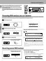
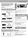
Pressing the DISPLAY key changes the contents of the display.
DISPLAY
1 PS (Program Service name) display:
The station name is displayed automatically when an RDS broadcast
is received,
If no PS data was sent, “NO PS” is displayed.
2 Frequency display:
Displays the frequency of the current station.
Each press switches the display mode as follows:
1 PS (Program Service name) display
2 Frequency display
3 RT (Radio Text) display
RDS
SP. A
ROOM A
RDS
SP. A
3 RT (Radio Text) display:
Text data accompanying the RDS broadcast scrolls across the
display. “NO RT” is displayed if the current RDS station does not
provide RT data.
Radio text can also be displayed on the on screen display using the
OSD functions.
°
ROOM A
RDS
SP. A
ROOM A
FM
FM
1)2.5)
FM
BBC 1
--
ABCDEFG HI
MHz
FM
Listening to radio broadcasts
KR-V999D (En/T)
28
Before listening to an RDS broadcast, follow the instructions
below to store the RDS stations in the preset memory.
Up to 40 stations can be preset, and then receivied with the
touch of a single button.
This receiver uses the Radio Data System (RDS) to provide
convenient tuning functions like PTY search and EON reservation.
POWER
MACRO
SHIFT
AUDIO
VIDEO
TV
8
P. CALL
AUDIO−VIDEO SURROUND RECEIVER KR-V999D
P. CALL
4
BAND
6
¢
7
REC
BASS
FLAT
GUIDE
TREBLE
FLAT
2-CH
LEVEL
STANDBY DOWNMIX INDICATOR
1
TUNING/SKIP
2
3
4
5
6
7
8
9
0
DOLBY
DIGITAL
PRO LOGIC
3 STEREO
STEREO
SOURCE DIRECT
DSP
DIMMER
LOUDNESS
INPUT SELECTOR
VOLUME CONTROL
+10/
PTY SEARCH
VOLUME
ON/STANDBY
MUTE
−10
+10
−10
+10
DIRECT
MEMORY
AUTO
TUNING
BAND
MUTE TAPE 2 MONITOR
POWER
DOWN
-ON
SUBWOOFER
LISTEN
MODE
UP
–OFF
AV AUX
PHONES
SOUND
A
TRAITR
SPEAKERS
B
TA/NEWS/INFO.
PTY
DISPLAY
thermally reactive advanced instantaneous transistor
S−VIDEO
FUNCTION
SHIFT
THEME
FAV
1
2
3
TV/SAT/VID
4
+100
VIDEO L - AUDIO - R
SETUP
MENU
INFO
ALT AUD
5
6
REPEAT
RANDOM
7
8
9
ROOM A
DISPLAY
ROOM B
+10
0
ENT
Keys or controls used in this operation.
Presetting RDS stations (RDS AUTO MEMORY)
This function automatically stores up to 40 RDS stations in the preset memory. In order to use the EON and PTY functions, the
RDS stations must be stored in the preset memory using the RDS AUTO MEMORY function.
1 Set the input to tuner.
INPUT SELECTOR
Frequency display
89.))
Operations
2 Set the broadcast band to "FM".
AUTO
FM
MHz
Each press switches the band as follows:
1 FM
2 AM
BAND
SP. A
ROOM A
--
89.))
FM
MHz
"FM" is displayed
3 Store the stations automatically.
SP. A
Press and hold the "MEMORY"
key for more than 2 seconds.
ROOM A
AUTO ME MO
FM
Blinks
MEMORY
• After a few minutes, up to 40 RDS stations are preset in order from
channel "01".
• Stations already stored in the preset memory may be replaced by RDS
stations. (i.e., If the RDS AUTO MEMORY function finds 15 RDS
stations, the stations currently preset at numbers 01~15 are replaced
by the RDS stations.)
Receiving preset RDS stations
Press the numeric keys in the following order:
Enter the number of the preset
you want to receive (up to "40").
For "15", press 0,5
For "20", press 0,0,)
4
5
6
7
8
9
• If you make a mistake entering a two digit number, press the +10 key
several times to return to the original display and start again.
• To change the information in the display, press the DISPLAY key.
RDS
SP. A
ROOM A
15
89.))
FM
MHz
Listening to radio broadcasts
KR-V999D (En/T)
The RDS auto memory function assigns preset numbers to
RDS stations starting from preset number "1". Therefore, be
sure to execute the RDS auto memory function before using
the following operations to manually store AM stations and
other FM stations, and RDS stations.
“Presetting RDS stations (RDS AUTO MEMORY)”.
•
POWER
MACRO
29
SHIFT
AUDIO
VIDEO
TV
8
P. CALL
AUDIO−VIDEO SURROUND RECEIVER KR-V999D
P. CALL
BAND
6
4
DOLBY
DIGITAL
¢
PRO LOGIC
3 STEREO
7
REC
BASS
FLAT
GUIDE
TREBLE
FLAT
2-CH
LEVEL
STANDBY DOWNMIX INDICATOR
1
TUNING/SKIP
2
3
4
5
6
7
8
9
0
STEREO
SOURCE DIRECT
DSP
DIMMER
LOUDNESS
INPUT SELECTOR
VOLUME CONTROL
+10/
PTY SEARCH
VOLUME
ON/STANDBY
MUTE
−10
+10
−10
+10
DIRECT
MEMORY
AUTO
TUNING
BAND
MUTE TAPE 2 MONITOR
POWER
DOWN
-ON
SUBWOOFER
LISTEN
MODE
UP
–OFF
AV AUX
PHONES
SOUND
A
TRAITR
SPEAKERS
B
TA/NEWS/INFO.
PTY
DISPLAY
thermally reactive advanced instantaneous transistor
S−VIDEO
Preparation
FUNCTION
SHIFT
VIDEO L - AUDIO - R
SETUP
MENU
• Select tuner.
THEME
FAV
1
2
3
TV/SAT/VID
INFO
ALT AUD
4
+100
5
6
REPEAT
RANDOM
7
8
9
ROOM A
DISPLAY
ROOM B
+10
0
ENT
Keys or controls used in this operation.
Presetting radio stations manually
1 Tune to the station you want to
store.
2 Press the MEMORY key while receiving the station.
• In addition to the RDS auto memory function, RDS stations can also be
stored manually in the preset memory.
• When storing radio stations manually, it may take a few minutes before
the "MEMORY" indicator appears in the display after pressing the
MEMORY key depending on receiving conditions.
Blinks for 5 seconds
MEMORY
Lights for 5 seconds
89.))
)-
STEREO
TUNED
MHz
Operations
Proceed to step 3 within 5 seconds.
(If more than 5 seconds elapse, press
MEMORY again).
MEMORY
FM
Press the numeric keys in the following order:
3 Enter a preset number (1~40).
4
5
6
7
8
9
Receiving preset stations
For "15", press 0,5
For "20", press 0,0,)
• Repeat steps 1, 2 and 3 to store as many stations as necessary.
• If you store a station at a previously used preset, the old station will be
replaced by the new one.
• When RDS stations are stored manually in the preset memory, the PS
information may not be included in the memory depending on receiving
conditions.
Press the numeric keys in the following order:
1 Select tuner.
For "15", press 0,5
INPUT SELECTOR
For "20", press 0,0,)
• If you make a mistake entering a two digit number, press the +10 key
several times to return to the original display and start again.
2 Enter the number of the preset
you want to receive (up to "40").
4
5
6
7
8
Preset number stored in memory
9
SP. A
ROOM A
15
89.))
FM
MHz
Receiving preset stations in order (P.CALL)
When using the remote control, press AUDIO to select the
tuner control mode.
Preset numbers »
P. CALL
4
Preset numbers «
P. CALL
¢
• Each time you press the key, another preset station is received in order.
When you press ¢
1=2=3=
○
○
When you press 4
1+2+3+
○
○
○
○
38=39=40=1=2=3=
38+39+40+1+2+3+
○
○
○
○
○
○
○
○
Holding down the button, lets you skip through the presets,
receiving each for 0.5 seconds apiece.
Listening to radio broadcasts
KR-V999D (En/T)
30
This function lets you set the tuner to automatically search
for stations which are currently broadcasting the type of
program (genre) you want to listen to.
Under adverse receiving conditions, it may take more than 1
minute to complete the search.
POWER
MACRO
SHIFT
AUDIO
VIDEO
TV
8
P. CALL
AUDIO−VIDEO SURROUND RECEIVER KR-V999D
P. CALL
BAND
6
4
¢
7
REC
BASS
FLAT
GUIDE
TREBLE
FLAT
2-CH
LEVEL
STANDBY DOWNMIX INDICATOR
1
TUNING/SKIP
2
3
4
5
6
7
8
9
0
DOLBY
DIGITAL
PRO LOGIC
3 STEREO
STEREO
SOURCE DIRECT
DSP
DIMMER
LOUDNESS
INPUT SELECTOR
VOLUME CONTROL
+10/
PTY SEARCH
VOLUME
ON/STANDBY
MUTE
−10
+10
−10
+10
DIRECT
MEMORY
AUTO
TUNING
BAND
MUTE TAPE 2 MONITOR
POWER
DOWN
-ON
Preparations
• Execute the RDS auto memory procedure.
• Set the broadcast band to FM.
• Tune to an RDS station.
SUBWOOFER
LISTEN
MODE
UP
–OFF
AV AUX
PHONES
SOUND
A
TRAITR
SPEAKERS
B
TA/NEWS/INFO.
PTY
DISPLAY
thermally reactive advanced instantaneous transistor
S−VIDEO
FUNCTION
SHIFT
VIDEO L - AUDIO - R
SETUP
MENU
THEME
FAV
1
2
3
TV/SAT/VID
INFO
ALT AUD
4
+100
5
6
REPEAT
RANDOM
7
8
9
ROOM A
DISPLAY
ROOM B
+10
0
ENT
Keys or controls used in this operation.
Tuning by program type (PTY search)
1 Activate the PTY search mode.
RDS
PTY
PTY
SP. A
ROOM A
FM
NEWs
When an RDS broadcast is received, the program type is
shown on the display. If no PTY data is available, or if the
station is not an RDS station, “NONE” is displayed.
Operations
2 Select the program type you desire.
Use the program type table on the right for your convenience.
Program type table
A
A To select using the TUNING keys
Next
program type
TUNING
(
)
DOWN
Previous
program type
B
Program Type Name
Display
1
Pop Music
POP M
2
Rock Music
ROCK M
3
* M.O.R. Music
M.O.R. M
4
Light Classic Music
LIGHT M
5
Serious Classic Music
CLASSICS
6
Other Music
OTHER M
Weather
WEATHER
Select while "PTY" is lit.
The TUNING keys let you select from all
29 program types in the order shown at
right.
(
)
UP
B To select with the numeric keys
4
5
6
7
8
9
The numeric keys allow to you select
programme types 1 to 0 directly. If you
want to select one of the other programme types, use the TUNING key.
“NO DATA” is displayed if this operation is attempted
before performing the RDS Auto Memory operation.
Finance
FINANCE
Children's programmes
CHILDREN
Social Affairs
Social A
Religion
RELIGION
Phone in
PHONE IN
Travel
TRAVEL
Leisure
LEISURE
Jazz Music
JAZZ
Country Music
COUNTRY
Oldies Music
OLDIES
Folk Music
FOLK M
Documentary
DOCUMENT
7
News
NEWS
8
Current Affairs
AFFAIRS
9
Information
INFO
0
Sport
SPORT
Education
EDUCATE
Drama
DRAMA
Cultures
CULTURE
Science
SCIENCE
Varied Speech
VARIED
*M.O.R. Music (Middle of the Road Music)
• The operations shown in A can also be performed with the P.CALL
keys on the remote control.
Listening to radio broadcasts
KR-V999D (En/T)
31
3 Start the search.
EXAMPLE: Searching for a Rock Music broadcast.
Display while searching
+10/
PTY SEARCH
Blinks
RDS
PTY
SP. A
ROOM A
ROCK M
FM
Display when a station is received.
Goes out
To select another program type
Repeat steps 1, 2 and 3
RDS
SP. A
ROOM A
BBC 1 F M
FM
Station name display
• No sound is heard while “PTY” is blinking.
• If the desired program type cannot be found, “NO PROG” is displayed,
then after several seconds the display returns to the original display.
• If the desired program type is found, that program is received. The
program type display changes temporarily to the frequency display, and
then to the station name display.
Operations
Program type name display
Listening to radio broadcasts
KR-V999D (En/T)
32
When the receiver is tuned to an RDS EON station (a station
at which the EON indicator lights up), this function lets you
set the receiver to automatically switch stations to receive
news, traffic, or information programs as they are broadcast. When the broadcast is over, the receiver returns to the
original station automatically.
POWER
MACRO
SHIFT
AUDIO
VIDEO
TV
8
P. CALL
AUDIO−VIDEO SURROUND RECEIVER KR-V999D
P. CALL
4
BAND
6
¢
7
REC
BASS
FLAT
GUIDE
TREBLE
FLAT
2-CH
LEVEL
STANDBY DOWNMIX INDICATOR
1
TUNING/SKIP
2
3
4
5
6
7
8
9
0
DOLBY
DIGITAL
PRO LOGIC
3 STEREO
STEREO
SOURCE DIRECT
DSP
DIMMER
LOUDNESS
INPUT SELECTOR
VOLUME CONTROL
+10/
PTY SEARCH
VOLUME
ON/STANDBY
MUTE
−10
+10
−10
+10
DIRECT
MEMORY
AUTO
TUNING
BAND
MUTE TAPE 2 MONITOR
POWER
DOWN
-ON
SUBWOOFER
LISTEN
MODE
UP
–OFF
AV AUX
PHONES
SOUND
A
TRAITR
SPEAKERS
B
TA/NEWS/INFO.
PTY
DISPLAY
thermally reactive advanced instantaneous transistor
S−VIDEO
FUNCTION
SHIFT
MENU
Preparation
• Set the broadcast band to FM.
FAV
2
3
INFO
ALT AUD
4
+100
VIDEO L - AUDIO - R
SETUP
THEME
1
TV/SAT/VID
5
6
REPEAT
RANDOM
7
8
9
ROOM A
DISPLAY
ROOM B
+10
0
ENT
Reserving the desired information
Complete steps 1~3 of "Presetting RDS
1 stations
•
(RDS AUTO MEMORY)".
Note
Keys or controls used in this operation.
Skip this step if you have already completed the
RDS AUTO MEMORY procedure.
• The EON function will not work if all 40 FM preset stations were stored
manually using the procedure shown in “Presetting radio stations
manually”. Be sure to use the RDS automatic memory function.
2 Select the information you desire.
Display When "TA" is selected
TA
RDS
SP. A
TP
ROOM A
BBC 1 F M
FM
Operations
"TP" lights for stations where TP (Traffic Program) information can be
received.
TA/NEWS/INFO.
Each press switches the reservation mode as follows:
1 TA
2 NEWS
3 INFO.
4 off
(Traffic Announcement)
(News)
(Information)
(EON off)
• If “TA”, “NEWS” and “INFO” can not be selected, carry out the RDS
automatic memory function again.
•
3 Tune to a preset RDS station.
Press the numeric keys in the following order:
Choose an RDS preset station that displays both the "RDS" and "EON" indicators.
4
5
6
7
8
9
For "15", press 0,5
For "20", press 0,0,)
• If you make a mistake entering a two digit number, press the +10 key
several times to return to the original display and start again.
Display When "TA" is selected
TA
RDS
EON
SP. A
ROOM A
BBC 2 F M
FM
Be sure "EON" appears in the display
• If you want to reserve TA, receive a station with which the TP indicator
lights.
• When “EON” does not light although an RDS station is received, that
station is not transmitting EON data. Please select a different station.
Listening to radio broadcasts
KR-V999D (En/T)
33
for the information you selected while
4 Wait
listening to the current station.
The receiver will wait for the desired information to
start as long as the tuner is set to a preset RDS station
that displays both the "EON" and "RDS" indicators,
and the power is turned ON.
When listening to the tuner:
Be sure to stay tuned to stations that display both the “EON” and “RDS”
indicators.
1 Tune in a station which that displays both the “EON” and “RDS”
indicators, then use the INPUT SELECTOR to switch the input to the
source you desire.
2 Even when the INPUT SELECTOR is set to a source other than tuner,
it will automatically switch to tuner when the desired EON program
starts to broadcast. During this period, the source selected in step 1
continues playing, but will not be heard.
3 When reception of the desired EON program is complete, the INPUT
SELECTOR returns to the previous input source.
• When the power is OFF, the EON function does not operate.
• If a reserved EON program starts to broadcast during analog recording,
the INPUT SELECTOR switches to the tuner and the station broadcasting the EON program is recorded.
When waiting for information while
listening to a RDS station without the EON
function
If the “EON” indicator does not light in steps 3 and 4 and the desired
kind of information has already been selected, the information from
only the station being received will be waited for.
TP (Traffic Program) indication
When the “TP” indicator is lit, this means that the presently-received
station or a station in the same network is transmitting traffic
information. When “TP” is displayed for the station being received,
the traffic information of this station can be received without EON
reservation.
To cancel EON reservation
Turn the “TA”, “NEWS” and “INFO.”
indicators off.
TA/NEWS/INFO.
Each press switches the reservation mode as follows:
1 TA
2 NEWS
3 INFO.
4 off
(Traffic Announcement)
(News)
(Information)
(EON off)
Should be off
TA NEWS INFO.
RDS EON
SP. A
ROOM A
BBC 2 F M
FM
Operations
To listen sources other than the tuner:
Ambience effects
KR-V999D (En/T)
34
This receiver incorporates 4 different sound modes to let you enjoy surround sound with a wide variety of program sources.
The Dolby Digital (AC-3) and Dolby Pro Logic surround sound let you enjoy theater-like surround effects when you play Dolby
Digital (AC-3) and Dolby Pro Logic program sources (like Laserdiscs and DVDs). Dolby 3 Stereo creates a panoramic frontal
sound field while keeping dialog on screen. The Digital Signal Processing (DSP) modes let you create a variety of different sonic
environments from almost any type of program source.
To obtain the best possible surround sound, be sure to complete "Surround set up" before using the surround modes.*
Sound modes
Dolby Digital (AC-3)
Operations
The Dolby Digital (AC-3) surround format lets you enjoy up
to 5.1 channels of digital surround sound from Dolby digital
(AC-3) program sources (such as Laserdisc software marked
). Compared with previous Dolby surround,
Dolby Digital (AC-3) provides even better sound quality,
greater spatial accuracy, and improved dynamic range.
Some Dolby Digital (AC-3) programs carry information that
lets you compress the dynamic range of the sound track,
without degrading the sound quality, for softer sound
effects when you listen late at night ("Midnight mode").
‡
Note
Although a full set of speakers (front left, right, and center, rear left and
right, and a subwoofer) is required for true 5.1 channel Dolby Digital
(AC-3) surround sound, this receiver lets you enjoy Dolby Digital (AC-3)
(and Dolby Pro Logic) program sources, even if you connect only the
front speakers. ("Surround set up")
*
Center speaker
Subwoofer (LFE)*
Front Speaker
Surround speakers (stereo signal)
* LFE = Low Frequency Effects. This channel delivers separate nondirectional bass signals to the subwoofer for more dynamic deep bass
sound effects.
Although only Dolby Digital (AC-3) soundtracks incorporate a separate
low frequency channel, connecting a subwoofer will also improve
deep bass performance in the other surround modes.
Dolby Pro Logic
Center speaker
Dolby Pro Logic is a specially encoded 2 channel surround
format designed to provide theater-like surround sound
from Dolby Pro Logic program sources (such as video and
Laserdisc software marked
). This receiver
is equipped with a Dolby Pro Logic surround decoder to let
you enjoy the wide variety of currently available Dolby Pro
Logic home video software.
Subwoofer*
Front Speaker
Surround speakers (monaural signal)
* Optional in this mode.
Dolby 3 Stereo
Center speaker
Dolby 3 Stereo creates a panoramic frontal sound field
while maintaining the dialog in an on-screen position. This
mode is designed for use with Dolby program sources, but
can also improve sound field unity for non-Dolby program
sources. Dialog positioning and sound image definition,
however, may not be as accurate when used with nonDolby program sources.
Subwoofer*
Front Speaker
* Optional in this mode.
Ambience effects
KR-V999D (En/T)
35
DSP mode
* The DSP mode will produce a stereo-like surround effect from
monaural sources, but there will be some reduction in the presence
of the arena, jazz club, or stadium (etc.).
Center speaker
Subwoofer*
Front Speaker
Surround speakers
* Optional in this mode.
What's DSP?
DSP stands for Digital Signal Processor.
The way a sound is heard in an actual environment
depends on a variety of different factors. One of the most
important is reverberation (the act of decaying elements
of sound echoing in various places).
The DSP modes produce the feeling of presence by using
the DSP to create reverberation, without spoiling the
sound quality of the original signal.
Manufactured under licence from Dolby Laboratories Licensing Corporation. "Dolby","AC-3","Pro Logic" and the
double - D symbol are trademarks of Dolby Laboratories
Licensing Corporation.
Operations
The DSP mode lets you add the atmosphere of an arena,
jazz club, or stadium to almost any type of program source.*
These modes are particularly effective when used with
stereo program sources, like CD, television, and FM radio.
You might enjoy trying the STADIUM or ARENA mode the
next time you watch a concert or sporting event!
The WALL parameter lets you adjust the “brightness” of
the sonic environment according to your preference.‡
The ROOM SIZE parameter lets you adjust the size of the
sonic environment according to your preference.
‡
The EFFECT level lets you adjust the “presence” of the
sonic environment according to your preference.
‡
Ambience effects
KR-V999D (En/T)
36
DOLBY AC-3 can be used when playing DVD or LD software bearing the
mark and DOLBY DIGITAL (AC-3) format digital broadcasts (etc.). DOLBY PRO LOGIC and DOLBY 3 STEREO can be used when playing video, DVD, or LD software
bearing the
mark. DSP modes can be used with any source.
Be sure to complete "Surround set up" before using any of these surround modes.
*
Preparations
• Turn ON related components.
• Complete "Surround set up". *
• Set the INPUT SELECTOR to the
component you wish to play back
with surround sound.
Surround Play
1 Select the SOUND menu.
OSD
RT
S.DIR
SET
UP
DSP
STEREO
SOUND
Operations
AC-3
PRO LOGIC 3 STEREO
2 Select a surround mode.
Select the icon for the mode you desire. The selected icon turns blue. The surround mode settings are stored separately for each
input. Surround modes can also be selected by using the LISTEN MODE key on the remote control.
°
OSD
RT
S.DIR
SET
UP
DOLBY DIGITAL (AC-3)
DSP
When a Dolby Digital (AC-3) format signal is
input, press to select the Dolby Digital (AC-3)
mode. To select this icon, the input selector
must be set to VIDEO 2, 3, or 4. No sound will
be heard if selected when normal stereo
sources are input.
Turns on the current DSP mode and switches
to the DSP screen where you can adjust
various aspects of each DSP mode.
DOLBY (PRO LOGIC)
AC-3
PRO LOGIC 3 STEREO
DSP
STEREO
Midnight mode ‡
Source direct °
Displays set up menu °
OSD °
Radio Text °
Selects the DOLBY PRO LOGIC mode.
To select this icon, the surround speakers
must be selected.
*
DOLBY (3 STEREO)
Selects the DOLBY 3 STEREO mode.
To select this icon, the center speaker must
be selected.
*
STEREO
Cancels surround playback.
If selected when a Dolby Digital AC-3 signal
is input, the 2 CH DOWNMIX indicator on the
front panel lights up and the signals are
downmixed to 2 channel stereo.
Source Direct (S.DIR)
Lets you pass the source material direct to
the amplifier, bypassing any audio processing.
the SOUND key on the remote to turn off the on-screen display, then press either VIDEO, AUDIO, or
3 Press
TV key on the remote to cancel the OSD remote control mode.
4 Start playing the video software.
5 Adjust the volume.
Note
To enjoy Dolby Digital (AC-3) surround (as well as all the other surround modes) from a single component, be sure to use a Dolby Digital (AC3) compatible source component. Connect the Dolby Digital (AC-3) compatible source component's AC-3 format digital audio signal to one of
the DIGITAL INPUT jacks on the back of the receiver. Connect the normal audio signal correctly to the respective component's AUDIO jacks.
0!
Ambience effects
KR-V999D (En/T)
37
To select a DSP mode
1 Press the DSP icon.
OSD
RT
S.DIR
2 Select a DSP mode
SET
UP
WALL = MEDIUM
ARENA : Simulates the presence of an
indoor concert arena.
JAZZ CLUB : Simulates the presence
of a jazz club.
STADIUM : Simulates the presence of
an outdoor stadium.
CHURCH : Simulates the presence of a
church with high ceilings.
THEATER : Simulates the presence of
a movie theater.
ROOMSIZE = MEDIUM EFFECT LEVEL = 3
MAIN
AC-3
PRO LOGIC 3 STEREO
DSP
STEREO
ARENA
JAZZ CLUB
STADIUM CHURCH THEATER
To adjust the DSP modes
Adjusting the WALL type, ROOM SIZE, and EFFECT LEVEL lets you create different types of surround effects.
ROOMSIZE = MEDIUM EFFECT LEVEL = 3
MAIN
ARENA
JAZZ CLUB
STADIUM CHURCH THEATER
1 Select a parameter .
WALL : Lets you choose from 3 different wall types(SOFT, MEDIUM, HARD).
ROOM SIZE : Lets you choose from 3 different room sizes (SMALL, MEDUIM,
LARGE).
EFFECT LEVEL : Lets you choose from 5 different effect levels (1, 2, 3, 4, 5).
2 Adjust the parameter using the TUNING/SKIP keys on the remote control.
3 Press MAIN to return to the main sound menu or press the SOUND key on
the remote to turn off the on-screen display.
4 Press either VIDEO, AUDIO, or TV key on the remote to cancel the OSD
remote control mode.
Convenient functions
Midnight mode (Dolby Digital (AC-3) mode only)
When watching movies at night you might not be able to raise the
volume as loud as normal. Midnight mode compresses the dynamic
range of previously specified parts of the AC-3 sound track (like scenes
with sudden increases in volume) to minimize the difference in volume
between the specified and non-specified parts. This makes it easy to
hear all of the sound track, even when listening at low volumes.
1 Select the midnight mode icon.
2 Adjust the parameter using the TUNING/SKIP keys on
the remote control.
1
2
Off
Dark grey
Grey
Light grey
• Some Dolby Digital (AC-3) software may not be compatible with the
Midnight mode.
• Midnight mode has no effect on parts of the sound track that are not
specified for compression.
Display dimmer adjustent
DISPLAY
FUNCTION
SHIFT
The DIMMER key on the front panel lets you select the brightness of
the receiver's display. You might find this useful if you darken your
room to watch movies or listen to music.
When the remote control is set to operate a video component, the FUNCTION
FUNCTION SHIFT and DISPLAY key combination can also be used to
SHIFT
change the display on the respective video component.
\
0
SP. A
ROOM
A
PRO LOG IC
DISPLAY
\
0
SP. A
ROOM
A
PRO LOG IC
DISPLAY
FUNCTION
SHIFT
\
0
SP. A
ROOM
A
PRO LOG IC
Operations
WALL = MEDIUM
Ambience effects
KR-V999D (En/T)
38
OSD switch
When recording programs or watching movies you may want to turn of
the OSD display mode. When the OSD display mode is ON, each
operation of the remote control is displayed on the monitor TV. When
OSD display mode is OFF, the receiver will only shows the on-screen
display when the SOUND or SETUP keys are pressed.
SOURCE DIRECT switch
Lets you pass the source material direct to the amplifier, bypassing any
audio processing. When SOURCE DIRECT is ON, surround sound is
turned off and the tone controls are bypassed.
SET UP switch
Lets you access the SET UP screen if necessary. See "Surround setup"
for details regarding the SET UP screen.
*
Operations
RADIO TEXT switch
Lets you display radio text messages transmitted from the currently
tuned FM RDS station on the screen of your monitor TV (even if the
input selector is set to a different input). When RT is set to ON and a
radio text broadcast is received, the radio text scrolls across the bottom
of the monitor.
¶
Press to switch.
On
Off
OSD
OSD
Press to switch.
On
Off
S.DIR
S.DIR
Press to access the SET UP screen.
SET
UP
Press to switch.
On
RT
Off
RT
LISTEN MODE key
The LISTEN MODE key on the remote control lets you switch the
sound mode directly from the remote control.
LISTEN
MODE
Press to switch.
1 STEREO
2 AC-3
3 PRO LOGIC
4 3 STEREO
5 ARENA
6 JAZZ CLUB
7 STADIUM
8 CHURCH
9 THEATER
SUBWOOFER adjustment
Display when SUBWOOFER is pressed.
The SUBWOOFER key on the remote control lets you adjust the output
level of the subwoofer while listening to a favorite source.
First press the SUBWOOFER key to select the subwoofer operation
mode, then use the VOLUME key to adjust the output level.
SUBWOOFER
SP. A
ROOM
A
SW
«
+1 dB
SURROUND
The displayed value changes.
VOLUME
SP. A
ROOM
A
SW
+2 dB
SURROUND
KR-V999D (En/T)
Operations
39
Getting the most from your remote control
KR-V999D (En/T)
40
The remote control supplied with this receiver is also capable of controlling components from a variety of manufacturers once
you register the appropriate setup codes into the remote control unit.
Refer to "Remote operation of other components" for details about the operations available for each component.
P
* When registering setup codes for KENWOOD audio components which are connected to this unit by system control cords, use the
following codes to insure proper system control operation: Cassette: 7000, CD: 8099, MD: 9000.
@
To control other KENWOOD components (VCRs, LD players, audio components not connected with system control cords, etc.) follow
the procedure described below.
Low battery warning
Replace all four batteries with new ones when you notice a shortening of the distance from which the remote control will operate or if the remote control
blinks 5 times when you push a key. The remote control is designed to retain set up codes in memory while you change batteries.
Registering setup codes for other components
the setup code of the component to be
1 Find
registered.
Input
Component
Maker
Code
Key
(CD)
CD player
KENWOOD
8028, 8037
AUDIO
VIDEO 1
• Refer to the setup code lists to find the setup code for the
component to be registered.
W
Example: To register a CD made by KENWOOD, you would
enter "8037"
• If you purchase a new component that is not covered by the
setup code list, you can use the FutureSet upgrade feature.
o
VIDEO 2
VIDEO 3
VIDEO 4
TAPE1/MD
CD
down the ENT key until the backlight
2 Hold
flashes twice and remains lit.
PHONO
—
TV 1
—
TV 2
—
CABLE
ROOM B
ENT
• At this time all inputs become available regardless of any earlier
registration.
Remote Control
Perform each of the following steps within
5 seconds.
3 Select the component to be registered.
Press the VIDEO, AUDIO, or TV
key repeatedly to select the desired component.
AUDIO
VIDEO
TV
VIDEO key
1
2
3
4
AUDIO key
VIDEO1 (SAT)
VIDEO2 (LD)
VIDEO3 (VCR)
VIDEO4 (DSS)
1 CD (CD)
2 TAPE1/MD
(TAPE)
3 PHONO
TV key
1 TV1
2 TV2
3 CABLE
• Example : To register the component connected to the VIDEO 1 jacks,
select "VIDEO 1 (SAT)".
SP. A
ROOM A
A-sAT
Getting the most from your remote control
KR-V999D (En/T)
4 Enter the setup code.
41
MENU
THEME
FAV
1
2
3
TV/SAT/VID
INFO
ALT AUD
4
5
6
+100
REPEAT
RANDOM
8
9
7
• Example: Press 5258 to register a LD player made by KENWOOD.
• The backlight flashes once each time a number is entered.
• If an invalid setup code is entered the remote will output one long blink,
disregard that code and return to the beginning of step 4.
• If you push an invalid key, the remote will exit the setup mode.
DISPLAY
0
POWER, and check to see that the com5 Press
ponent you want to control turns on.
• PLAY or TUNING/SKIP (+/–) can also be used instead of POWER.
• If the component does not react, and there is more than one setup
code, enter another setup code and try again.
• If the component is already on, pressing POWER will turn it off.
POWER
the ENT key to store the code you have
6 Press
just input.
The backlight flashes twice.
• This code replaces any previous setup codes entered for the respective
component.
ROOM B
steps 3 through 6 to register additional
7 Repeat
components until all components have been
registered.
setup codes have been entered for all
8 Once
components, hold down the ENT key until the
backlight flashes twice.
ROOM B
ENT
Note
• If you have components that are not remote controllable, like a record
player (etc.), you will need to register a Non-IR code at the respective
input. This keeps the respective input in the remote control's cyclic list
so you can select it using the remote control. Please consult the
owner's manual of the components you are connecting for information
regarding remote controllability. The list of Non-IR codes is included at
the beginning of the Set up code chart.
Q
• This operation should take about 3 seconds.
• Once registered, the display on the receiver shows the component
type instead of the default input name.
Example: if you register a VCR at the VIDEO 1 jacks, "VCR" appears
instead of "VIDEO 1(SAT)".
• Both the default input name and the component type (i.e., " VIDEO1
'VCR' ") are shown in the on screen display when the OSD mode is set
to ON.
°
• After initial setup, any VIDEO (VIDEO 1, 2, 3, 4) or TV (TV1, TV2, CABLE)
inputs that have not been programmed with a setup code or Non-IR
code are deleted from the cyclic list (except for the "AV AUX" VIDEO
input). The PHONO input will be deleted if a Non-IR code was not
registered.
• The INPUT SELECTOR on the front panel of the receiver always cycles
through all inputs.
Although each setup code is designed to work with a number of different models, certain codes may not work with some models. (Also,
certain codes may only operate some of the functions available on a given model.)
Remote Control
ENT
Getting the most from your remote control
KR-V999D (En/T)
POWER
42
MACRO
SHIFT
AUDIO
VIDEO
TV
8
P. CALL
P. CALL
4
BAND
6
¢
7
REC
GUIDE
TUNING/SKIP
VOLUME
MUTE
SUBWOOFER
LISTEN
MODE
FUNCTION
SHIFT
MENU
SOUND
SETUP
THEME
FAV
1
2
3
TV/SAT/VID
INFO
ALT AUD
4
5
6
+100
REPEAT
RANDOM
7
8
9
ROOM A
DISPLAY
ROOM B
+10
0
ENT
Keys or controls used in this operation.
Operating other components
This operation lets you operate the registered components.
KENWOOD audio components with system control turn on and off automatically with the receiver via the system control
connections.
@
1 Use the VIDEO, AUDIO, or TV keys to
select the component you desire.
AUDIO
VIDEO
• Pressing the VIDEO or AUDIO key also changes the input selector on
the receiver. If you do not want to change the current input, press the
SHIFT key before step 1.
e
TV
VIDEO key
1
2
3
4
5
2 Press the SHIFT key and then press the
POWER key (within 3 seconds).
SHIFT
VIDEO1 (VCR 1)
VIDEO2 (VCR 2)
VIDEO3 (LD)
VIDEO4 (DVD)
AV AUX
AUDIO key
1 CD (CD)
2 TAPE1/MD
(TAPE)
3 TUNER
4 PHONO
TV key
1 TV1
2 TV2
3 CABLE
• Pressing the SHIFT key is only required when turning the selected
component on or off. Pressing the POWER key directy turns the
receiver on and off.
\
\ ER
3 Press the operation keys you desire.
• See "Remote operation of other components" at the end of this manual
for a list of keys available with each component.
P
Remote Control
BAND
6
Note
The remote control mode remains in the set at the component selected in step 1 mode until you select another
component (etc.).
Be sure to point the remote control at the remote sensor on the receiver when you want to operate KENWOOD components connected by
system control cords. Otherwise, point the remote control at the component you want to operate.
Getting the most from your remote control
KR-V999D (En/T)
This operation lets you change the remote control operation
mode without changing the input selector.
You may find this useful when you want to control one
component while using another. (For example, if you want
to rewind the tape deck while listening to a CD.)
This operation is also useful if you don't know the which
mode the remote control is set to. Executing this operation
allows you to change or reconfirm the operation mode you
desire.
POWER
MACRO
SHIFT
43
AUDIO
VIDEO
TV
8
P. CALL
P. CALL
4
BAND
6
¢
7
REC
GUIDE
TUNING/SKIP
VOLUME
MUTE
SUBWOOFER
LISTEN
MODE
FUNCTION
SHIFT
MENU
SOUND
SETUP
THEME
FAV
1
2
3
TV/SAT/VID
INFO
ALT AUD
4
5
6
+100
REPEAT
RANDOM
7
8
9
ROOM A
DISPLAY
ROOM B
+10
0
ENT
Keys or controls used in this operation.
Changing (confirming) the operation mode
1 Press SHIFT.
• To operate a TV, start from step 2.
SHIFT
Go to step 2 within 3 seconds.
2 Select the component to be controlled.
AUDIO
VIDEO
3 Execute the desired operations.
TV
SP. A
ROOM A
CD The component to be controlled is displayed in parenthesis
• Pressing any other keys after the SHIFT key cancels the shift function
and sends the normal code associated with the respective key.
• The input selector does not change during this operation.
• The remote control mode is shown in the on screen display when the
OSD mode is set to ON.
°
• If you press VIDEO or AUDIO key more than 3 seconds after pressing
the SHIFT key, the input selector changes together with the operation
mode.
• See "Remote operation of other components" for a list of keys available
with each component.
P
The operation mode remains set at the component specified
in step 2.
To return control to the original component, press SHIFT and
then press the VIDEO or AUDIO key to return to the original
control mode.
Remote Control
Press the VIDEO, AUDIO or TV
key repeatedly to display the remote control mode for the component you want to control.
Getting the most from your remote control
KR-V999D (En/T)
44
The macro play function allows you to set the remote to
control several components in succession. After completing
this setup, you can perform a series of operations automatically. Enter the setup codes for the components you want to
control beforehand.
POWER
MACRO
SHIFT
AUDIO
VIDEO
TV
8
P. CALL
P. CALL
4
BAND
6
¢
7
REC
GUIDE
TUNING/SKIP
VOLUME
MUTE
SUBWOOFER
LISTEN
MODE
FUNCTION
SHIFT
MENU
SOUND
SETUP
THEME
FAV
1
2
3
TV/SAT/VID
INFO
ALT AUD
4
5
6
+100
REPEAT
RANDOM
7
8
9
ROOM A
DISPLAY
ROOM B
+10
0
ENT
Keys or controls used in this operation.
Preparing for automatic operations (MACRO play)
a plan of the macro play you want to
1 Make
set up.
The order of the operations may be fairly complex and you may
not be remember all of the necessary commands during the
setup procedure.
Use the space provided below to write down the operations in
the order you are going to enter them.
1
-
2
=
3
~
4
!
5
@
6
#
7
$
8
%
9
^
0
&
• Up to 20 steps can be memorized for each macro.
• The example below shows the plan for step 4 (which occupies a total
of 9 steps) :
1
2
3
4
Total
TV + SHIFT + POWER
FUNCTION SHIFT + 4
VIDEO + VIDEO
SHIFT + POWER
3 steps
2 steps
2 steps
2 steps
9 steps
• If you attempt to store more than 20 steps, the remote will output one
long blink and exit the macro programming mode.
• Enter channel numbers (for the monitor TV, etc.) exactly as you would
using the original remote.
Remote Control
2 Activate the macro program mode.
Press and hold the MACRO key
until the backlight flashes twice.
MACRO
Perform each of the following steps within
5 seconds.
Getting the most from your remote control
KR-V999D (En/T)
3 Select where the macro should be stored.
Press the VIDEO, AUDIO, or TV
key to select the macro location.
(MACRO1, 2, and 3 respectively)
AUDIO
VIDEO
TV
45
• You can store up to 3 different macros, one at each key:
VIDEO = "MACRO 1", AUDIO = "MACRO 2", TV = "MACRO 3"
• The backlight flashes once when you select the macro location.
• Pressing a button other than VIDEO, AUDIO, or TV cancels the macro
program mode.
When VIDEO is pressed
SP. A
ROOM A
MACRO 1
4 Press the keys to be operated in order.
EXAMPLE:
1 Press TV > SHIFT > POWER to
turn on the TV.
SHIFT
TV
\
\ER
• This example shows you how to create a macro that: turns on the TV,
sets the TV to the appropriate input, selects the receiver's input
selector to LD, and turns on the LD player. All you have to do is insert
the laser disc!
• In order to allow verification of the remote control mode, the name of
the selected input appears in the receiver's display when the VIDEO,
AUDIO or TV key is pressed. When the VIDEO or AUDIO key is
pressed the receiver's input also changes.
2 Press FUNCTION SHIFT > "4" (TV/
SAT./VIDEO) to set the TV to the
appropriate video input.
TV/SAT./VID
\
FUNCTION
SHIFT
4
3 Press VIDEO twice to select the
LD player registered at VIDEO 2.
Remote Control
VIDEO
4 Press SHIFT and POWER to turn
on the LD player.
SHIFT
\
\ ER
5 Terminate the macro program mode.
Press the MACRO key so that the
backlight flashes twice.
• The macro is stored at the locations specified in step 3. If another
macro was previously stored at the same location, it is erased.
MACRO
Repeat steps 1 through 5 to program up to 3 macros.
Getting the most from your remote control
KR-V999D (En/T)
POWER
46
MACRO
SHIFT
AUDIO
VIDEO
TV
8
P. CALL
P. CALL
4
BAND
6
¢
7
REC
GUIDE
TUNING/SKIP
VOLUME
MUTE
SUBWOOFER
LISTEN
MODE
SOUND
FUNCTION
SHIFT
MENU
SETUP
THEME
FAV
1
2
3
TV/SAT/VID
INFO
ALT AUD
4
5
6
+100
REPEAT
RANDOM
7
8
9
ROOM A
DISPLAY
ROOM B
+10
0
ENT
Keys or controls used in this operation.
Executing an automatic operation
1 Press the MACRO key.
MACRO
Go to step 2 within 3 seconds.
2 Execute the macro play.
Press the VIDEO, AUDIO, or TV
key to execute the corresponding macro play.
AUDIO
VIDEO
TV
• "MACRO" appears in the front panel and on-screen display and the pre
programmed macro is performed:
VIDEO = "MACRO 1", AUDIO = "MACRO 2", TV = "MACRO 3"
• The remote control flashes once for each command output.
• The remote control will output OSD information to tell you the status
of the macro.
• Some devices take up to 1 second to power on. The macro function has
an automatic delay after any power function output.
• Pressing a button other than AUDIO, VIDEO, or TV cancels the macro
program mode.
When VIDEO is pressed
Remote Control
SP. A
ROOM A
MACRO 1
Getting the most from your remote control
KR-V999D (En/T)
If you make connections to another room, you can use the
remote control to select source components and to adjujst
the volume (etc.) output to the other room.
%
POWER
MACRO
TV
8
P. CALL
* KENWOOD system control operations are only possible when the
remote control is set to the Room A operation mode. In order to avoid
malfunctions, do not make system control connections to audio components which you plan on controlling with the Room B operations
described below.
P. CALL
4
BAND
6
¢
7
REC
GUIDE
TUNING/SKIP
VOLUME
MUTE
SUBWOOFER
LISTEN
MODE
FUNCTION
SHIFT
MENU
Only sources connected to the analog AUDIO (L and R)
and VIDEO jacks can be output to ROOM B.
47
SHIFT
AUDIO
VIDEO
SOUND
SETUP
THEME
FAV
1
2
3
TV/SAT/VID
INFO
ALT AUD
4
5
6
+100
REPEAT
RANDOM
7
8
9
ROOM A
DISPLAY
ROOM B
+10
0
ENT
Keys or controls used in this operation.
Controlling the sound in another room (ROOM B)
1 Select a speaker system.
* Audio and video signals are output from the SECOND ROOM PRE
OUT jacks regardless of the setting of the SP. A/B and ROOM A/
B indicators.
A
SPEAKERS
B
A ON
SP.
A
B
ROOM
A
B
A-PHONO
The indicator for the speakers and room you want to use
should be lit.*
the remote control to the ROOM B
2 Set
operation mode.
Press the FUNCTION SHIFT key
and then press the ENT (ROOM
B) key within 3 seconds.
: Select to output sound to ROOM A from the speaker
connected to the SPEAKERS A terminals. This setting allows you to enjoy surround playback in ROOM
A while outputting sound to ROOM B via the SECOND ROOM PRE OUT jacks.
B ON
: Select to output sound to ROOM B via the speakers
connected to the SPEAKERS B terminals. Be sure to
turn off the subwoofer in ROOM A if one is connected.
A+B ON : Select to output sound to ROOM A from the speakers
connected to the SPEAKERS A terminals and output
sound to ROOM B from the speakers connected to
the SPEAKERS B terminals.
ROOM A automatically switches to stereo playback
(surround playback is not possible).
A+B OFF : No sound from the speakers. Use this setting when
listening with headphones in ROOM A for stereo
sound in all playback modes or to listen in ROOM B via
the SECOND ROOM PRE OUT jacks.
ROOM B
\
• The MUTE and VOLUME +/– keys let you control the sound level in
ROOM B.
ENT
Remote Control
FUNCTION
SHIFT
3 Select the desired component.
Press the VIDEO or AUDIO key
repeatedly to set the ROOM B
input selector to the component
you desire.
SP.
A
B
ROOM
A
B
B-CD
ROOM B input selector
AUDIO
VIDEO
4 Execute the desired operations.
TV
• The setting of the ROOM B input selector also appears in the on screen
display.
• The component selected for ROOM B can also be operated using the
keys on the remote control. See "Remote operation of other components" for a list of keys available with each component.
P
The remote remains in the ROOM B operation mode until
you switch back to the ROOM A operation mode.
To return to the ROOM A operation mode, press the FUNCTION
SHIFT key and then press the +10 (ROOM A) key within 3
seconds.
Getting the most from your remote control
KR-V999D (En/T)
POWER
48
MACRO
SHIFT
AUDIO
VIDEO
TV
8
P. CALL
P. CALL
4
BAND
6
¢
7
REC
GUIDE
TUNING/SKIP
VOLUME
MUTE
SUBWOOFER
LISTEN
MODE
FUNCTION
SHIFT
MENU
SOUND
SETUP
THEME
FAV
1
2
3
TV/SAT/VID
INFO
ALT AUD
4
5
6
+100
REPEAT
RANDOM
7
8
9
ROOM A
DISPLAY
ROOM B
+10
0
ENT
Keys or controls used in this operation.
Setup code correlation
Deleting a setup code
1 Hold down the ENT key until the backlight flashes twice.
2 Select the component to be deleted.
Press the VIDEO, AUDIO, or TV key repeatedly to select the
desired component.
• At this time all inputs become available regardless of any earlier
registration.
• Example 1 : To delete the registration of the component connected to
the VIDEO 1 jacks, select "VIDEO 1".
3 Enter the 3 digit code "991".
4 Hold down the ENT key until the backlight flashes twice.
Perform each step within 5 seconds.
• To resume the factory settings, proceed step 1, then enter “981”.
Checking a setup code
1 Hold down the ENT key until the backlight flashes twice.
2 Select the component with setup code you want to check.
Press the VIDEO, AUDIO, or TV key repeatedly to select the
desired component.
3 Enter the 3 digit code "990".
• The backlight flashes twice immediately after the "0" is input to confirm
input.
Remote Control
4 Press the 1 key and count the number of times the backlight
blinks. This is the first number of the 4 digit setup code.
• If the backlight does not blink, the first digit in the setup code is 0.
5 Press the 2 key and count the number of times the backlight
blinks. This is the second number of the 4 digit setup code.
• If the backlight does not blink, the second digit in the setup code is 0.
6 Press the 3 key and count the number of times the backlight
blinks. This is the third number of the 4 digit setup code.
• If the backlight does not blink, the third digit in the setup code is 0.
7 Press the 4 key and count the number of times the backlight
blinks. This is the fourth number of the 4 digit setup code.
• If the backlight does not blink, the fourth digit in the setup code is 0.
Perform each step within 5 seconds.
Getting the most from your remote control
KR-V999D (En/T)
FutureSet allows you to update the remote control so it can
operate new components which do not appear in the setup
code list at the end of the manual.
This function allows you to register new setup codes for any
or all of the following command positions:
VIDEO1, VIDEO2, VIDEO3, VIDEO4, TV1, TV2, CABLE, CD,
TAPE1/MD.
FutureSet codes are stored in memory. Each time a FutureSet
upgrade is performed, any previous information in the FutureSet
memory location is erased. Please inform your customer service
representative if FutureSet has been previously used.
FutureSet upgrade option
POWER
MACRO
49
SHIFT
AUDIO
VIDEO
TV
8
P. CALL
P. CALL
4
BAND
6
¢
7
REC
GUIDE
TUNING/SKIP
VOLUME
MUTE
SUBWOOFER
LISTEN
MODE
FUNCTION
SHIFT
MENU
SOUND
SETUP
THEME
FAV
1
2
3
TV/SAT/VID
INFO
ALT AUD
4
5
6
+100
REPEAT
RANDOM
7
8
9
ROOM A
DISPLAY
ROOM B
+10
0
ENT
Keys or controls used in this operation.
(This service will be available until 31 May 1999)
down the brand name and model
1 Write
number of your component in the space
provided before you call.
Type
Brand
Model No.
TV
KENWOOD
KV?-????
Remote Model No.
RC-????
1
Call our Free-Phone Consumer Help-Line
2 and
explain which components you would
like to add to your remote control.
UK (including N. Ireland) : 0800-898520
• The free phone upgrade service is not available in countries other than
listed above.
• For customers outside the U.K., please contact your Kenwood dealer
who will be able to assist you.
• This number is designed specifically for Future Set upgrades, questions
about system operation should be first addressed to your place of
purchase.
2
3
• After the customer service representative records the brand name and
model number of your component, he/she will ask you to hold the
remote to the speaker portion of your telephone as shown below.
Your remote control is KENWOOD model number: RC-R0905
• The hours for cutomer service are:
Monday-Friday
9:00 am - 7:00 pm (Greenwich time)
Saturday
9:00 am - 3:00 pm (Greenwich time)
Complete steps 3 and 4 before holding the remote to the
speaker portion of your telephone.
down the ENT key until the backlight
3 Hold
flashes twice.
ROOM B
ENT
Go to step 4 within 5 seconds.
4 Enter the 3 digit code "997".
RANDOM
9
\
• The backlight flashes twice.
• The remote is now in the upgrade mode. The remote will wait for 30
seconds for a valid telephone download signal. If nothing is received
within this time, it will revert to normal operation.
RANDOM
9
\
+100
7
Go to step 5 within 30 seconds.
continued on next page
Remote Control
• At this time all inputs become available regardless of any earlier
registration.
Getting the most from your remote control
KR-V999D (En/T)
50
your remote to the speaker portion of
5 Hold
your telephone.
• For each setup code the operator can supply a setup code number.
Should you ever need to change your input configuration, this number
can be used. Please record for your future reference. If for some reason
this information is lost, see "Checking a setup code" in the "Setup code
correlation" section for further information.
Code selection after mode download
After successful completion of the download, step 5 above, the remote control automatically enters a special set-up mode which works
as described below.
the component for which you want
1 Select
to register the information downloaded
above.
Press the VIDEO, AUDIO, or TV
key repeatedly to select the desired component.
AUDIO
VIDEO
TV
VIDEO key
1
2
3
4
VIDEO1 (VCR 1)
VIDEO2 (VCR 2)
VIDEO3 (LD)
VIDEO4 (DVD)
AUDIO key
1 CD (CD)
2 TAPE1/MD
(TAPE)
3 PHONO
TV key
1 TV1
2 TV2
3 CABLE
• Example 1 : To register a code at the component connected to the
VIDEO 1 jacks, select "VIDEO 1 (VCR)".
Perform each of the following steps within
5 seconds.
2 Press a numeric key.
Remote Control
MENU
THEME
FAV
1
2
3
TV/SAT/VID
INFO
ALT AUD
4
5
6
+100
REPEAT
RANDOM
8
9
7
• Press the 1 key to output the POWER code of the first component on
your list in step 1 of the previous page. Continue to push buttons 2
through 9 (and 0) until the component you want to register turns on.
• Though the FutureSet memory in your remote control is quite large,
only 10 setup POWER codes can be put on the 10 keypad at any one
time. If you require a larger download, the standard setup procedure
can be used. See "Registering setup codes for other components", your
customer service representative can supply you with the downloaded
setup code numbers.
DISPLAY
0
steps 1 and 2 to register all of the
3 Repeat
downloaded information.
down the ENT key until the backlight
4 Hold
flashes twice.
ROOM B
ENT
• The setup code for the last POWER code to be sent in step 2 is
automatically registered at the location selected in step 1.
• At this time, the remote exits the special set-up mode and returns to
its normal operation mode.
Set up code chart
KR-V999D (En/T)
Non-IR codes
51
8900
Satellite
2900
DVD
6900
Cassette deck
7900
TV
1900
MD
8900
LD player
5900
VCR
4900
Phono
0900
Set up codes
Maker
Set up codes
Maker
Set up codes
Action
4317
De Graaf
4042
Harmon/Kardon
4038
Adventura
4000
Decca
4000, 4081
Harwood
4072
Aiko
4278
Dual
4041
HCM
4072
Aiwa
4000, 4307, 4406
Dumont
4000, 4081, 4104
Headquarter
4046
Akai
4041, 4315
Dynatech
4000
HI-Q
4047
Akiba
4072
Elcatech
4072
Hinari
4072, 4240
Alba
4278, 4295
Electrohome
4037
Hitachi
American High
4035
Electrophonic
4037
4000, 4041, 4042,
4240
Amstrad
4000
Emerex
4032
Hypson
4072
Anam
4162, 4240
Emerson
4000, 4002, 4037,
4043, 4121, 4184,
4211, 4278, 4295,
4361
Imperial
4000
Interfunk
4081
ITT
4041, 4046, 4104,
4240
ESC
4240, 4278
ITV
4037, 4278
Ferguson
4041
Jensen
4041
Fidelity
4000
JVC
4008, 4041, 4067
Finlandia
4081, 4104
Kaisui
4072
Finlux
4000, 4042, 4081,
4104
KEC
4037, 4278
Firstline
4037, 4043, 4045,
4072
Kenwood
4038, 4041, 4067
KLH
4072
Fisher
4046, 4047, 4066,
4104
Maker
Anam National
4162, 4454
Anitech
4072
ASA
4037, 4081
Asha
4240
Asuka
4037
Audiovox
4037
Baird
4000, 4041, 4104
Basic Line
4072, 4278
Beaumark
4240
Bell & Howell
4104
Blaupunkt
4034, 4162
Brandt Electronic
4041
Broksonic
4121, 4184, 4211,
4295, 4361
Kodack
4035, 4037
Korpel
4072
Fuji
4033, 4035
Lenco
4278
Fujitsu
4000
Leyco
4072
4000
4037, 4081
Bush
4072, 4278
Funai
4000
Lloyd
Calix
4037
Garrard
4000
Loewe
4035, 4060
Logik
4072, 4240
Luxor
4043, 4046, 4048,
4104
LXI
4037
M Electronic
4000
Magnavox
4035, 4039, 4081,
4149
Canon
4035
GE
4081
GEC
4081
CCE
4072, 4278
Go Video
4232, 4350
CGE
4000
GoldHand
4072
Cimline
4072
Goldstar
Citizen
4037, 4278
Goodmans
Colt
4072
4000, 4037, 4072,
4278
Craig
4037, 4047, 4072,
4240
Gradiente
4000
Graetz
4041, 4104, 4240
Crown
4072, 4278
Granada
4046, 4081, 4104
Curtis Mathes
4035, 4041, 4060
Grandin
4000, 4037, 4072
Cybernex
4240
Grundig
4034, 4072, 4081
Daewoo
4045, 4046, 4278
Hanseatic
4037
Dansai
4072
Harley Davidson
Carver
4037, 4038
4000
Magnin
4240
Manesth
4045, 4072
Marantz
4035, 4081, 4295
Marta
4037
Matsui
4295
Matsushita
4035, 4162, 4454
MEI
4035
Other
VCR Set up codes
Operations
Preparations
CD player
Set up code chart
KR-V999D (En/T)
5 2 VCR Set up codes (continued)
Maker
Set up codes
Maker
Set up codes
Maker
Set up codes
Memorex
4000, 4035, 4037,
4039, 4046, 4047,
4048, 4104, 4240,
4307
Pioneer
4067, 4081
Silva
4037
Profitronic
4240
Singer
4045, 4072
Proline
4000
Sinudyne
4081
Protec
4072
Sontec
4037
Pulsar
4039
Sony
Pye
4081
4032, 4033, 4034,
4035
Quarter
4046
STS
4042
Quartz
4046
Sunstar
4000
4035, 4077, 4162,
4454
Suntronic
4000
Sylvania
4000, 4035, 4043,
4081
4000
Memphis
4072
Preparations
Metz
4162, 4454
MGA
4043
MGN Technology
4240
Minolta
4042
Mitsubishi
4043, 4067, 4081,
4173
Motorola
4035, 4048
MTC
4000, 4240
Multitech
4000, 4072
Murphy
4000
NAD
4104
NEC
4038, 4041, 4067,
4104
Operations
Neckermann
4081
Nesco
4072
Nikko
4037
Quasar
Quelle
4081
Radio Shack
4000, 4037
Symphonic
4081
Tandy
4000, 4104
Radix
4037
Tashiko
4000
Randex
4037
Tatung
4000, 4041, 4081
RCA
4042, 4060, 4077,
4149, 4225
Teac
4000, 4041
Technics
4035, 4162
Realistic
4000, 4035, 4037,
4046, 4047, 4048,
4066, 4104, 4240
Teknika
4000, 4035, 4037
Teleavia
4041
Radiola
Rex
4041
Nikon
4034
Ricoh
4034
Noblex
4240
Roadstar
4037, 4072, 4240,
4278
Runco
4039
Nokia
4041, 4046, 4048,
4104, 4240
Nordmende
4041
Saba
4041
Oceanic
4000, 4041
Salora
4043, 4046
Okano
4315
Samsung
4045, 4240
Olympus
4035
Sanky
4039, 4048
Optimus
4037, 4048, 4104,
4162, 4454
Sansui
4041, 4067
Sanyo
4046, 4047, 4104,
4240
Orion
4121, 4295
Osaki
4000, 4037, 4072
SBR
4081
Otto Versand
4081
Schaub Lorentz
4000, 4041, 4104
Palladium
4037, 4041, 4072
Schneider
4000, 4072, 4081
Panasonic
4035, 4077, 4162,
4454
Scott
4043, 4045, 4121,
4184, 4211
Pathe Marconi
4041
Penny
4035, 4037, 4038,
4042, 4240
Pentax
4042
SEG
4240
Perdio
4000
SEI
4081
Philco
4035, 4038
Sears
Selco
4035, 4037, 4042,
4046, 4047, 4066,
4104
4041
Philips
4035, 4081
Sharp
4048
Phonola
4081
Shintom
4072, 4104
Pilot
4037
Shogun
4240
Siemens
4037, 4081, 4104
Telefunken
4041
Tenosal
4072
Tensai
4000
Thomson
4041
Thorn
4041, 4104
TMK
4240
Toshiba
4041, 4043, 4045,
4060, 4066, 4081
Totevision
4037, 4240
Uher
4240
Unitech
4240
Universum
4000, 4037, 4081,
4240
Vector
4045
Vector Research
4038
Victor
4008, 4041, 4067
Video Concepts
4045
Videosonic
4240
Wards
4000, 4035, 4042,
4047, 4048, 4060,
4072, 4149, 4240
XR-1000
4000, 4035, 4072
Yamaha
4038
Yamishi
4072
Yokan
4072
Yoko
4240
Zenith
4033, 4034, 4039
Other
Set up code chart
KR-V999D (En/T)
Maker
Set up codes
Maker
Set up codes
Admiral
1093
GE
1019, 1030, 1056
1046
Nesco
1179
Aiko
1092
1021, 1027, 1047,
1051, 1055, 1135,
1178, 1282, 1451
NEC
Adventura
Nikko
1030, 1092, 1178
Akai
1030
Noshi
1018
Alleron
1179
NTC
1092
Ambassador
1177
Amstrad
1177
Anam
1180
Anam National
1055, 1250
AOC
1019, 1030, 1137
Audiovox
1180
Belcor
1019
Bell & Howell
1016, 1154
Blue Star
1282
BPL
1282
Bradford
1180
Brockwood
1019
Bush
1282
Candle
1030, 1046, 1056,
1186
Carnivale
1030
Carver
1054
Celebrity
1000
Citizen
1030, 1039, 1046,
1056, 1060, 1092,
1186, 1280
General
1186
Gibralter
1017, 1019, 1030
Goldstar
1019, 1030, 1039,
1056, 1178
Goodmans
1179
Grandin
1282
Grunpy
1179, 1180
Hallmark
1178
Onwa
1180
Optimus
1154, 1166, 1250
Optonica
1093, 1165
Orion
1177, 1236
Panasonic
1051, 1055, 1250
Penny
1018, 1019, 1021,
1027, 1030, 1039,
1047, 1051, 1060,
1135, 1156, 1178
Harvard
1180
HCM
1282
Hinari
1179
Hisawa
1282
Philco
1019, 1030, 1054
Hitachi
1056, 1145, 1151
Philips
1054
Hypson
1282
Pilot
1019, 1030, 1039
Infinity
1054
Pioneer
1166
Janeil
1046
Portland
1019, 1039, 1092
JBL
1054
Prism
1051
JCB
1000
Proscan
1047
JVC
1053
Proton
1031, 1178, 1466
Kaisui
1282
Pulsar
1017, 1019
KEC
1180
Quasar
Kenwood
1019, 1030
1051, 1055, 1165,
1250
Kloss
1024, 1046
Radio Shack
KTV
1030, 1039, 1180,
1280
1019, 1030, 1039,
1047, 1056, 1154,
1165, 1178, 1180
RCA
1018, 1019, 1047,
1090, 1135
Realistic
1019, 1030, 1039,
1056, 1154, 1165,
1178, 1180
Runco
1017, 1030
Concerto
1056
Contec
1180
Craig
1180
Logik
1016
Crown
1039, 1180
Luxman
1056
Curtis Mathes
1030, 1039, 1060,
1154
LXI
1047, 1054, 1154,
1156, 1178
CXC
1180
Magnavox
Daewoo
1019, 1039, 1092,
1154, 1451
1024, 1030, 1054,
1186, 1187
Majestic
1016
Daytron
1019
Marantz
1030, 1054
Dumont
1017, 1019
Matsui
1177
Electroband
1000
Matsushita
1250
Electrohome
1381
Megatron
Emerson
1019, 1039, 1154,
1177, 1178, 1179,
1180, 1236, 1280,
1282, 1463
Memorex
Saisho
1177
Sampo
1030, 1039
Samsung
1019, 1030, 1039,
1056, 1060, 1178,
1427
1145, 1178
Samsux
1039
1016, 1056, 1150,
1154, 1178
Sanyo
1154, 1159
Scimitsu
1019
MGA
1019, 1030, 1150,
1178
Scotch
1178
Scott
Midland
1017, 1039, 1047,
1051, 1135
1019, 1178, 1179,
1180, 1236
Sears
1047, 1054, 1056,
1154, 1156, 1159,
1178, 1179
Envision
1030
Finlux
1179
Fisher
1154, 1159
Minutz
1021
Fortress
1093
Mitsubishi
1019, 1150, 1178
1179
Motorola
1055, 1093
SEI
1177
Funai
1179, 1180
MTC
Sharp
1039, 1093, 1165
Futuretech
1180
1019, 1030, 1056,
1060
Shogun
1019
Multitech
1180
Signature
1016
NAD
1156, 1166, 1178
Simpson
1186, 1187
Fujitsu
Operations
Set up codes
Other
Maker
Preparations
53
TV Set up codes
Set up code chart
KR-V999D (En/T)
5 4 TV Set up codes (continued)
Preparations
Maker
Set up codes
Maker
Set up codes
Maker
Set up codes
Sinudyne
1177
Tatung
1055
Triumph
1177
Sony
1000
Technics
1051, 1250
Universal
1027
Soundesign
1178, 1179, 1180,
1186
Technol Ace
1179
Vector Research
1030
Techwood
1051, 1056
Victor
1053, 1250
Spectricon
1137
Teknika
1054
1019, 1180
Vidtech
1019, 1178
Starlite
1180
Viking
1046, 1312
Supra
1056
1016, 1019, 1039,
1054, 1056, 1060,
1092, 1150, 1179,
1180, 1186, 1312
Vidikron
SSS
Wards
Supre-Macy
1046
Supreme
1000
Sylvania
1030, 1054, 1381
1016, 1019, 1021,
1027, 1030, 1054,
1056, 1165, 1178,
1179
Tandy
1039, 1093
Tera
1031
TMK
1056, 1177, 1178
Tomashi
1282
Toshiba
1060, 1154, 1156
Yamaha
1019, 1030
Totevision
1039
Zenith
1016, 1017
Satellite Set up codes
Operations
Maker
Set up codes
Maker
Set up codes
Maker
Set up codes
Echostar
2280
Jerrold
2361
Realistic
2052
General Instrument
2361
Primestar
2361
Uniden
2052
LD player Set up codes
Maker
Set up codes
Maker
Set up codes
Maker
Set up codes
Carver
5194
Mitsubishi
5059
Quasar
5204
Disco Vision
5023
NAD
5059
Sega
5023
Hitatchi
5023
Panasonic
5204
Sony
5201
Kenwood
5258
Philips
5194
Telefunken
5059
Magnavox
5194
Pioneer
5023, 5059
Theta Digital
5194
Marantz
5194
Set up codes
Maker
Set up codes
Maker
Set up codes
Alphastar
3772
Jerrold
3627
RCA
3566
Echostar
3775
Panasonic
3701
Sony
3639
HTS
3775
Primestar
3627
Toshiba
3790
DSS Set up codes
Maker
Hughes Network Systems 3749
Other
DVD Set up codes
Maker
Set up codes
Panasonic
6490
Toshiba
6503
Set up code chart
KR-V999D (En/T)
Set up codes
Maker
Set up codes
Maker
Set up codes
ABC
0001, 0003, 0007,
0008, 0011, 0013,
0014, 0017
Hitachi
0011
Scientific Atlanta
0008, 0017, 0477
Hytex
0007
Signal
0015, 0040
Jasco
0153
Signature
0011
Jerrold
0003, 0011, 0012,
0014, 0015, 0276,
0476
SL Marx
0040
Sprucer
0021
Antronix
0022
Archer
0022, 0153, 0797
Belcor
0056
Cable Star
0056
Memorex
0000
Cabletenna
0022
Movie Time
0063, 0156
Cableview
0022
NSC
0063, 0156
Century
0153
Oak
0007, 0019
Citizen
0153
Panasonic
0000, 0021, 0107
Colour Voice
0025
Paragon
0000
Comtronics
0040
Philips
0025, 0153
Contec
0019
Pioneer
0144, 0753
Daeryung
0008
Prelude
0770
Eastern
0002
Pulsar
0000
Everquest
0015, 0040
PVP Stereo Visual Matrix 0003
Garrard
0153
Radio Shack
0797
GC Electronics
0056
RCA
0021
Gemini
0015
Regal
0020, 0259
General Instrument
0011, 0276, 0476
Regency
0002
GoldStar
0040, 0144
Rembrandt
0011
Hamlin
0009, 0020, 0034,
0259
Runco
0000
Samsung
0040, 0144
Starcom
0003, 0015
Stargate
0015, 0040, 0770
Starquest
0015
STS
0156
Sylvania
0001
Tandy
0258
Teleview
0040
Texscan
0001
Tocom
0012, 0013
Toshiba
0000
Tusa
0015
TV86
0063
Unika
0022, 0153
United Artists
0007
United Cable
0003
Universal
0022, 0056, 0153
Viewstar
0063, 0258
Zenith
0000, 0525
Operations
Maker
Preparations
55
Cable Set up codes
Maker
Set up codes
Maker
Set up codes
Maker
Set up codes
Aiwa
8124, 8157
Krell
8157
QED
8157
Arcam
8157
Linn
8157
Quad
8157
AudioTon
8157
LXI
8305
Quasar
8029
California Audio Lab 8029
Magnavox
8157
RCA
8053, 8179, 8305
Carver
8157, 8179
Marantz
8029, 8157
Realistic
8179
Cyrus
8157
Matsui
8157
Revox
8157
Denon
8003
MCS
8029
Rotel
8157
DKK
8000
Memorex
8032, 8305
SAE
8157
Dynamic Bass
8179
Meridian
8157
Sansui
8157, 8305
Elektra
8393
Micromega
8157
Sanyo
8179
Emerson
8305
Mission
8157
Scott
8305
Fisher
8048, 8088, 8179
NAD
8000
Sears
8305
Garrard
8393
Naim
8157
Sharp
8037
Genexxa
8032, 8305
NSM
8157
Sony
Goodmans
8305
Onkyo
8101
8000, 8185, 8604,
8605
Grundig
8157
Optimus
8000, 8032, 8037,
8179, 8305, 8468
Soundesign
8145
Tandy
8032
Hitachi
8032
JVC
8072, 8655
Panasonic
8029, 8303
Teac
8393
8028, 8037, 8048,
8099, 8190, 8858,
8859
Philips
8157
Technics
8029, 8303
Pioneer
8032, 8305, 8468
Universum
8157
Proton
8157
Victor
8072
Yamaha
8036, 8187
Kenwood
Other
CD Player Set up codes
Set up code chart
KR-V999D (En/T)
5 6 DAT deck Set up codes
Maker
Set up codes
Maker
Preparations
Set up codes
Maker
Set up codes
Carver
7158
Denon
7031
Marantz
7158
Sony
7093
Philips
7158
Technics
7158
Grundig
7158
Set up codes
Maker
Set up codes
Maker
Set up codes
Aiwa
7029, 7197
JVC
7244, 7273, 7274
Revox
7029
Arcam
7076
Kenwood
7000, 7071, 7183
Sansui
7009, 7029
Carver
7029
Magnavox
7029
Sony
7170, 7243, 7291
Denon
7076
Marantz
7009, 7029
Teac
7308, 7309
Fisher
7074
Onkyo
7136
Technics
7229
Garrard
7308, 7309
Optimus
7027, 7220
Victor
7244, 7273, 7274
Grundig
7029
Panasonic
7229
Wards
7027
Inkel
7071
Philips
7029
Yamaha
7094, 7097
Pioneer
7027, 7220
Cassette deck Set up codes
Maker
Operations
MD Set up codes
Maker
Set up codes
Kenwood
9000, 9826
Sony
9490
Misc. audio Set up codes
Maker
Set up codes
Maker
Set up codes
Maker
Set up codes
Jerrold
8459, 8520
Scientific Atlanta
8460
Starcom
8459
Other
In case of difficulty
KR-V999D (En/T)
Resetting the Microcomputer
With the power cord plugged in, turn the POWER key
OFF. Then, while holding down the ON/STANDBY key,
press POWER.
If the microcomputer may malfunction (unit cannot be operated, or
shows an erroneous display) if the power cord is unplugged while the
power is ON, or due to some other external factor. If this happens,
execute the following procedure to reset the microcomputer and
return the unit to its normal operating condition.
• The speaker cords are disconnected.
• VOLUME is set to the minimum position.
• MUTE is ON.
• The SPEAKERS switches are set to OFF.
Remedy
• Connect them properly referring to “Connecting the speakers”
#
• Adjust the volume to a proper level.
• Turn OFF the MUTE.
¡
• Set the SPEAKERS switch(es) to ON. )
The standby indicator blinks and sound is
not output.
• Speaker cords are short-circuited.
• Turn the power off, eliminate the shortcircuiting, then turn on the power again.
#
Sound is not output from one of the speakers.
• The speaker cord is disconnected.
• The speaker balance is set to an extreme
position.
• Connect it properly referring to “Connecting
the speakers”.
• Adjust the speaker levels using the test tone.
(
Sound is not output from the rear (surround) speakers and/or the center speaker,
or their sound is very small.
• The rear speaker cords and/or the center
speaker cord is disconnected.
• A surround mode has not been engaged.
• The rear and/or center volume controls are set
to the minimum level.
• Connect it properly referring to “Connecting
the speakers”.
• Select a surround mode.
• Adjust the speaker levels using the test tone.
(
A humming noise is generated when the
PHONO input selector is selected.
• The audio cord from the turntable is not connected to the PHONO jacks.
• The turntable is not grounded.
• Insert the audio cord plugs securely into the
PHONO jacks.
• Connect the grounding wire to the GND terminal on the rear panel.
The initial sound is intermittent when starting playback from an AC-3 source in a DVD
player.
• There are differnent causes for different types
of DVD players.
• With certain DVD players, the initial sound
may be intermittent.
No sound when playing a DVD.
• A PCM source is being played back.
• Press the STEREO key.
Digital playback is not possible from Dolby
Digital (AC-3) sources.
• The sound mode is set to "STEREO".
• Press the DOLBY DIGITAL key to select the
Dolby Digital (AC-3) mode.
Operations
No sound from the speakers.
Cause
Preparations
• Please note that resetting the microcomputer will clear the contents
of the memory and returns the unit to the state it was in when it left
the factory.
Amplifier
Symptom
57
Tuner
Cause
Remedy
Radio Stations cannot be received.
• No antenna is connected.
• The broadcast band is not set properly.
• The frequency of the desired station is not
tuned.
• Connect an antenna.
• Set the broadcast band properly.
• Tune the frequency of the desired station.
∞
Interference.
• Noise due to ignition noise from an automobile.
• Noise due to interference from an electric
appliance.
• Noise due to a nearby TV set.
• Install the outdoor antenna away from the
road.
• Turn off the power to the appliance.
• The preset station belongs to a frequency that
cannot be received.
• The preset memory was cleared because the
power cord had been unplugged for a long
period of time.
• Preset a station with a receivable frequency.
A station which was preset cannot be received by pressing the corresponding numeric key.
• Install the receiver farther away from the TV.
• Preset the station again.
Other
Symptom
In case of difficulty
KR-V999D (En/T)
5 8 Remote control unit
Symptom
Cause
Remedy
Preparations
The backlight flashes five times during normal operation.
• The batteries are nearing exhaustion.
• Replace with new batteries to preserve the
currently registered setup information.^
Subwoofer volume cannot be adjusted.
• Subwoofer is OFF.
• Turn the subwoofer ON.
Certain inputs cannot be selected using
the remote control.
• No preset codes registered at for the respective input(s).
• Register a preset code or Non-IR code at the
respective input(s).
·
Remote control operation is not possible.
• The remote control is set to a different operation mode.
• Batteries are exhausted.
• Press VIDEO, AUDIO, or TV to select the
approriate operation mode.
• Replace with new batteries. If the backup is
exhasted before you can replace the batteries, redo the setup procedure. ^‚
• Operate the remote control unit within the
controllable range.
Operations
• The remote control unit is too far away from
the main system, controlling angle is too large,
or there is an obstacle between the receiver
and the remote.
• The audio cords and system control cords are
not connected properly.
• No software is loaded in the source component.
• An attempt is made to play a tape which is
being recorded in the cassette deck.
• The remote control has not been set to the
operation mode for the component you wish
to control.
• The remote control is in the Room B (A)
operation mode.
• The microprocessor of the remote control
malfunctions.
Note
*
• Connect properly referring to “Setting up the
system”.
8
• Place software in the source component you
want to play.
• Wait until recording has completed.
• Press the VIDEO, AUDIO, or TV key to activate
the operation mode for the component you
want to control before operation.
e
• Change the operation mode.
u
• Reset the microprocessor.
i
Do not use contact cleaning agents because they could cause a malfunction. Be specifically careful against using contact cleaning agents
containing oil, since they may deform the plastic components.
Memory back up function
Please note that the following items will be deleted from
the unit's memory if the power cord is disconnected from
the AC outlet or the main power switch is turned off for
approximately 3 days.
Other
• Power mode.
• Settings made using OSD (like SURROUND SET UP).
• Input selector settings.
• Volume level.
• Broadcast band.
• Frequency setting.
• Preset stations.
Specifications
Caution : Read this page carefully to ensure safe operation.
KR-V999D (En/T)
FM tuner section
Rated power output during STEREO operation
(DIN) 1 kHz, 0.7% at 4 Ω ............................. 150 W + 150 W
(IEC) 63 Hz ~ 12.5 kHz, 0.7% at 4 Ω ......... 150 W + 150 W
Rated power output during SURROUND operation
FRONT(1kHz, 0.7% T.H.D. at 4 Ω) ........... 150 W + 150 W
CENTER (1kHz, 0.7% T.H.D. at 4 Ω) ....................... 150 W
SURROUND(1kHz, 0.7% T.H.D. at 4 Ω) .. 150 W + 150 W
Total harmonic distortion ............ 0.005 % (1kHz, 75 W, 4 Ω)
Frequency response
CD ...................................... 5 Hz ~ 85 kHz, +0.5 dB, –3 dB
Signal to noise ratio (DIN)
PHONO (MM) ............................................................ 62 dB
CD .............................................................................. 60 dB
Input sensitivity / impedance
PHONO (MM) ............................................ 2.5 mV / 47 kΩ
CD ............................................................. 200 mV / 47 kΩ
Output level / impedance
TAPE REC ................................................. 200 mV / 470 Ω
PRE OUT (FRONT, CENTER, SURROUND, SUBWOOFER)
........................................................................ 1 V / 1.2 kΩ
Tone control
BASS ................................................... ±10 dB (at 100 Hz)
TREBLE ................................................ ±10 dB (at 10 kHz)
LOUDNESS control
VOLUME at -40dB level ... +7 dB(100 Hz), +3 dB(10 kHz)
Tuning frequency range ....................... 87,5 MHz ~ 108 MHz
Usable sensitivity (DIN, 75 Ω)
MONO ......... 1.2µV / 13.2 dBf (40 kHz DEV., S/N 26 dB)
STEREO ........ 35µV / 42.1 dBf (46 kHz DEV., S/N 46 dB)
Total harmonic distortion (DIN, 1 kHz)
MONO ............................................ 0.2 % (65.2 dBf input)
STEREO .......................................... 0.5 % (65.2 dBf input)
Signal to noise ratio (DIN weighted, 1 kHz)
MONO .................... 65 dB (40 kHz DEV., 65.2 dBf input)
STEREO .................. 60 dB (46 kHz DEV., 65.2 dBf input)
Stereo separation (DIN, 1 kHz) ..................................... 40 dB
Selectivity (DIN, ±300 kHz) ............................................ 64 dB
Frequency response (30 Hz ~ 15kHz) ........ +0.5 dB, –3.0 dB
Sampling frequency ....................... 32 kHz, 44.1 kHz, 48 kHz
Input level / impedance / wave length
Optical .................... -15 dBm ~ -21 dBm, 600 nm ±30nm
Coaxial ....................................................... 0.5 Vp-p / 75 Ω
VIDEO section
Video format ............................... PAL/NTSC auto switching
VIDEO inputs / outputs
VIDEO
(composite) ................................. 1 Vp-p / 75 Ω
S-VIDEO (luminance signal) ..................... 1 Vp-p / 75 Ω
(chrominance signal) .......... 0.286 Vp-p / 75 Ω
Tuning frequency range ........................ 531 kHz ~ 1,602 kHz
Usable sensitivity (30% mod., S/N 20 dB)
........................................................... 16 µV / (600 µV/m)
Signal to noise ratio (30 % mod., 1 mV input) ............ 48 dB
GENERAL
Power consumption ...................................................... 420 W
AC outlet
SWITCHED ......................................... 2 (total 90 W max.)
Dimensions ........................................................... W : 440 mm
......................................................................... H : 162 mm
......................................................................... D : 392 mm
Weight (Net) .................................................................... 13 kg
RF Demodulator (DEM-999D)
Input level
AC-3 RF ...................................... 50 mV p-p ~ 200 mV p-p
RF Frequency responce ........................ 2.88 MHz ~ ±144 kHz
Output level / Impedance
Coaxial ....................................................... 0.5 Vp-p / 75 Ω
Dimensions ............................................................. W : 89 mm
........................................................................... H : 35 mm
......................................................................... D : 101 mm
Weight (Net) .................................................................... 200 g
KENWOOD follows a policy of continuous advancements in development. For this reason specifications may be changed without notice.
Other
Note
AM tuner section
Operations
DIGITAL AUDIO section
59
Preparations
AUDIO section
Remote operation of other components
KR-V999D (En/T)
60
Refer to the following for the type of remote control operations available for each component.
The setup code for each component must be entered beforehand.
• When pressing keys in succession, press each key firmly and be sure
to wait at least 1 second before pressing the next key.
• Numeric keys function the same as the numeric keys on the original
remote.
• To execute a FUNCTION SHIFT command, press the FUNCTION
SHIFT key, then press the corresponding key within 3 seconds.
1 Use the AUDIO, VIDEO, or TV keys to select the component
you want to control.
2 Press the keys corresponding to the operations you desire.
Refer to the following sections for details.
Preparations
Notes
‚
1. Although each setup code is designed to work with a number of different models, certain codes may not work with some models. (Also,
certain codes may only operate some of the functions available on a given model.)
2. The charts below show the typical functions available for each component. Some manufacturers use different key combinations to perform
similar functions. For that reason, we have programmed extra functions on some of the unused number keys to help you control your
equipment. To find if your component has extra functions, press the FUNCTION SHIFT key, then press a number key. Repeat this procedure
for each number key.
Tuner operations
TUNING/SKIP
Cassette deck operations
FUNCTION
SHIFT
8
P. CALL
MENU
THEME
1
2
3
TV/SAT/VID
INFO
ALT AUD
P. CALL
BAND
6
4
FAV
4
5
6
+100
REPEAT
RANDOM
7
8
9
¢
7
TUNING/SKIP
Operations
6
7
4
¢
4
+ (3 Play)
– (2 Play)
(BAND ∞
)
FUNCTION SHIFT commands
(AUTO ∞
)
DISPLAY (Dimmer ‡)
(P.CALL – ª )
(P.CALL + ª )
CD player operations
P. CALL
REC
(¶ Record)
P. CALL
BAND
4
6
¢
7
+ (Disc Skip +) 6 (Play/Pause {for SL16})
– (Disc Skip –) 6 (3 Play {for other})
8 (Pause {for other})
7 (Stop)
4 (Skip)
¢ (Skip)
MENU
THEME
FAV
MENU
THEME
1
2
3
1
2
3
TV/SAT/VID
INFO
ALT AUD
TV/SAT/VID
INFO
ALT AUD
P. CALL
8
4
5
6
4
5
6
REPEAT
RANDOM
+100
REPEAT
RANDOM
7
8
9
7
8
9
ROOM A
DISPLAY
ROOM B
DISPLAY
+10
0
ENT
0
Numeric keys
6
P. CALL
¢
7
Other
+ (¡ Search)
– (1 Search)
6
8
7
4
¢
FUNCTION SHIFT commands
REPEAT (Repeat)
RANDOM (Random)
DISPLAY (Dimmer)
FUNCTION
SHIFT
BAND
4
FAV
+100
MD recorder operations
TUNING/SKIP
6
8
7
4
¢
FUNCTION
SHIFT
8
(3 Play)
(Pause)
(Stop)
(Skip back)
(Skip forward)
P. CALL
6
¢
7
DISPLAY
ROOM B mode: P.CALL +/– only
TUNING/SKIP
8
BAND
0
TUNING ∞
P. CALL
MENU
THEME
FAV
MENU
THEME
1
2
3
1
2
FAV
3
TV/SAT/VID
INFO
ALT AUD
TV/SAT/VID
INFO
ALT AUD
4
5
6
4
5
6
+100
REPEAT
RANDOM
+100
REPEAT
RANDOM
7
8
9
7
8
9
ROOM A
DISPLAY
ROOM B
DISPLAY
+10
0
ENT
0
Numeric keys
FUNCTION SHIFT commands
+100 (+100)
REPEAT (Repeat)
RANDOM (Random)
DISPLAY (Dimmer)
(3 Play)
(Pause)
(Stop)
(1 Rewind)
(¡ Fast forward)
Remote operation of other components
KR-V999D (En/T)
TV operations
P. CALL
BAND
4
6
¢
7
+ (Channel +)
– (Channel –)
6 (Mute)
8 (Volume +)
7 (Volume –)
1
2
3
TV/SAT/VID
INFO
ALT AUD
4
5
6
+100
REPEAT
RANDOM
7
8
9
ROOM A
DISPLAY
ROOM B
+10
0
ENT
Numeric keys
VCR operations
TUNING/SKIP
P. CALL
8
P. CALL
6
¢
7
+ (Channel +)
– (Channel –)
6
8
7
4
¢
P. CALL
(3 Play)
(Pause)
(Stop)
(1 Rewind)
(¡ Fast forward)
8
P. CALL
6
¢
7
+ (A, A/B)
– (B)
6
8
7
4
¢
(3 Play)
(Pause)
(Stop)
(Skip back)
(Skip forward)
Satellite tuner operations
TUNING/SKIP
P. CALL
8
P. CALL
BAND
4
6
¢
7
+ (Channel +)
– (Channel –)
6
8
7
4
¢
FAV
3
TV/SAT/VID
INFO
ALT AUD
4
5
6
+100
REPEAT
RANDOM
8
9
7
DISPLAY
0
FUNCTION SHIFT commands
TV/SAT./VID (Input selector)
ALT AUDIO (Alternate audio)
+100 (TV TEXT)
REPEAT (Text off)
RANDOM (MIX)
THEME
FAV
MENU
THEME
1
2
3
1
2
3
TV/SAT/VID
INFO
ALT AUD
TV/SAT/VID
INFO
ALT AUD
FAV
4
5
6
4
5
6
+100
REPEAT
RANDOM
+100
REPEAT
RANDOM
7
8
9
7
8
9
ROOM A
DISPLAY
ROOM B
DISPLAY
+10
0
ENT
0
Numeric keys
REC
(¶ Record)
GUIDE
FUNCTION SHIFT commands
TV/SAT./VID (Input selector)
(OSD menu)
FUNCTION
SHIFT
BAND
4
2
MENU
LD player operations
TUNING/SKIP
THEME
1
FUNCTION
SHIFT
BAND
4
MENU
Preparations
8
FAV
Operations
P. CALL
THEME
(Select)
(»)
(«)
(|)
(\)
MENU
THEME
FAV
MENU
THEME
1
2
3
1
2
FAV
3
TV/SAT/VID
INFO
ALT AUD
TV/SAT/VID
INFO
ALT AUD
4
5
6
4
5
6
+100
REPEAT
RANDOM
+100
REPEAT
RANDOM
7
8
9
7
8
9
ROOM A
DISPLAY
ROOM B
DISPLAY
+10
0
ENT
0
Numeric keys
GUIDE
(OSD menu)
FUNCTION SHIFT commands
INFO (Frame- time)
REPEAT (Repeat)
RANDOM (Random)
DISPLAY (Display)
FUNCTION
SHIFT
MENU
THEME
FAV
MENU
THEME
1
2
3
1
2
3
TV/SAT/VID
INFO
ALT AUD
TV/SAT/VID
INFO
ALT AUD
4
5
6
4
5
6
+100
REPEAT
RANDOM
+100
REPEAT
RANDOM
7
8
9
7
8
9
ROOM A
DISPLAY
ROOM B
DISPLAY
+10
0
ENT
0
Numeric keys
FAV
FUNCTION SHIFT commands
TV/SAT./VID (Input selector)
ALT AUDIO (Alternate audio)
+100 (+100)
GUIDE
(OSD menu)
Other
TUNING/SKIP
61
FUNCTION
SHIFT
MENU
Remote operation of other components
KR-V999D (En/T)
62
Cable tuner operations
FUNCTION
SHIFT
MENU
TUNING/SKIP
P. CALL
8
P. CALL
BAND
4
6
¢
7
Preparations
+ (Channel +)
– (Channel –)
6
8
7
4
¢
THEME
FAV
MENU
THEME
1
2
3
1
2
3
TV/SAT/VID
INFO
ALT AUD
TV/SAT/VID
INFO
ALT AUD
4
5
6
4
5
6
+100
REPEAT
RANDOM
+100
REPEAT
RANDOM
7
8
9
7
8
9
ROOM A
DISPLAY
ROOM B
DISPLAY
+10
0
ENT
0
Numeric keys
(Select)
(»)
(«)
(|)
(\)
DVD player operations
TUNING/SKIP
P. CALL
8
6
P. CALL
¢
Operations
7
+ (Disc skip +)
– (Disc skip –)
6
8
7
4
¢
GUIDE
(OSD menu)
FUNCTION SHIFT commands
MENU (Menu)
THEME (Theme)
FAV. (Favorite)
TV/SAT./VID (Input selector)
INFO (Page)
ALT AUDIO (Alternate audio)
+100 (+100)
FUNCTION
SHIFT
BAND
4
FAV
(3 Play)
(Pause)
(Stop)
(Skip back)
(Skip forward)
MENU
THEME
FAV
MENU
THEME
1
2
3
1
2
3
TV/SAT/VID
INFO
ALT AUD
TV/SAT/VID
INFO
ALT AUD
FAV
4
5
6
4
5
6
+100
REPEAT
RANDOM
+100
REPEAT
RANDOM
7
8
9
7
8
9
ROOM A
DISPLAY
ROOM B
DISPLAY
+10
0
ENT
0
Numeric keys
FUNCTION SHIFT commands
ALT AUDIO (Alternate audio)
+100 (+100)
REPEAT (Repeat)
RANDOM (Random)
DISPLAY (Display)
REC
(¶ Record)
GUIDE
(OSD menu)
Other
Other
Operations
Preparations
KR-V999D (En/T)
63
For your records
Record the serial number, found on the back of the unit, in the spaces
designated on the warranty card, and in the space provided below. Refer
to the model and serial numbers whenever you call upon your dealer for
information or service on this product.
Model __________________ Serial Number ________________________
For the United Kingdom
Factory fitted moulded mains plug
1. The mains plug contains a fuse. For replacement, use only a 13-Amp ASTA-approved (BS1362) fuse.
2. The fuse cover must be refitted when replacing the fuse in the moulded plug.
3. Do not cut off the mains plug from this equipment. If the plug fitted is not suitable for the power points in your home or the cable is too
short to reach a power point, then obtain an appropriate safety approved extension lead or adapter, or consult your dealer.
If nonetheless the mains plug is cut off, remove the fuse and dispose of the plug immediately, to avoid a possible shock hazard by
inadvertent connection to the mains supply.
IMPORTANT
The wires in the mains lead are coloured in accordance with the following code.
Blue : Neutral
Brown : Live
Do not connect those leads to the earth terminal of a three-pin plug.