1
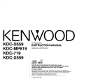
KENWOOD
KDC-219
KDG2019V
KDC-2019
KDG29MR
KDC-119
KDG119S
KDC-217
KDG217S
CD-RECEIVER
INSTRUCTION
AMPLI-TUNER-LECTEUR
MANUAL
DE CD
MODE D’EMPLOI
REPRODUCTOR DE DISCOS COMPACTOS RECEPTOR DE FM/AM
MANUAL DE INSTRUCCIONES
RECEPTOR DE CD
MANUAL DE INSTRU@ES
KENWOOD CORPORATION
Take the time to read through this instruction manual. Familiarity with installation and operation procedures will help you obtain the best performance from
your new CD-receiver.
For your records
Record the serial number, found on the back of the unit, in the spaces designated on
the warranty card, and in the space provided below. Refer to the model and serial
numbers whenever you call upon your KENWOOD dealer for information or service on
the product.
Model KDC-219, KDC2019V, KDC-2019, KDC-29MR. KDC-119,
COMPACT
KDC-1 19S, KDC-217, KDC217S Serial number
0 864-2114-00
(KWN)
0
do!3E
DIGITAL
AUDIO
Warning . . . . . . . . . . . . . . . . . . . . . . . . . . . . . . . . . . . . . . . 3
Safety precautions
. . . ..-.............
4
6
About CDs ..~................................
General features . . . . . . . . . . . . . . . . . . . . . . . . . 7
Power
Selecting the Source
Volume
Attenuator
Loudness
System Q
Audio Control
Speaker Setting
Clock Display
Adjustrng Clock
DSI (Disabled System Indicator)
Theft Deterrent Faceplate
Tuner features
. . . . . . . . . . . . . . . . ..-.....
CD/External
disc control
features . . . . . . ..-......................
12
Playing CD
Playing External Disc
Fast Forwarding and Reversing
Track Search
Album Search
Track/Album Repeat
Track Scan
Random Play
Magazrne Random Play
Basic Operations
of remote......
15
Loading and Replacing the battery
Basic operatrons
In Tuner source
In Disc source
10
Tuning Mode
Tuning
Statron Preset Memory
Auto Memory Entry
Preset Tuning
CRSC (Clean Reception System Crrcurt)
Accessories
. . . . . . . . . . . . . . . . . . . . . . . . . . . . . . . 17
Installation
Procedure . . ..-....... 17
Connecting
Wires to Terminals 18
. . . . . . . . . . . . . . . . . . . . . . ..-..... 19
Installation
Guide . . . . . . . . . . . ..2 1
Troubleshooting
. . . . . . . . . . . . . . . . . . . . . . . . . . -24
Specifications
A Warning
1ACAUTION
)
Use of controls or adjustments or performance
of procedures other than those specified
herein may result in hazardous radiation
exposure.
In compliance with Federal Regulations,
following are reproductions of labels on, or
inside the product relating to laser product
safety.
KENWOOD CORP CERTIFIESTHIS EQUIPMENT
CONFORMS TO DHHS REGULATIONSNO21 CFR
1040. 10. CHAPTER 1, SUBCHAPTERJ.
Location : Bottom Panel
FCC WARNING
Thus equipment may generate or use radio
frequency energy. Changes or modificatrons to
thus equtpment may cause harmful
Interference unless the modifications are
expressly approved In the rnstructron manual.
The user could lose the authority to operate
thus equrpment If an unauthorized change or
modifrcatron IS made.
(
Thus equipment has been tested and found to
comply with the limits for a Class B digital
device, pursuant to Part 15 of the FCC Rules.
These limits are designed to provide
reasonable protectlon against harmful
interference in a residential installation. This
equipment may cause harmful interference to
radio communications, if it is not installed and
used In accordance with the instructrons.
However, there IS no guarantee that
interference will not occur in a particular
installation. If this equipment does cause
harmful interference to radio or television
reception, which can be determrned by turning
the equipment off and on, the user IS
encouraged to try to correct the Interference
by one or more of the following measures:
l Reorient or relocate the receiving antenna.
l Increase the separation
between the
equipment and receiver.
l Connect the equipment
into an outlet on a
circuit drfferent from that to whrch the
recerver is connected.
l Consult the dealer or an experienced
radio/TV technician for help.
This Class B digital apparatus complres with
Canadian ICES-003.
-3-
piiiaKE
piii%Eq
To prevent injury or fire, take the
following precautions:
To prevent damage to the machine,
take the following precautions:
l
l
l
l
l
l
l
Insert the unrt all the way In untrl It is fully
locked in place. Otherwise it may fall out of
place when jolted.
When extending the ignition, battery, or
ground wares, make sure to use automotivegrade wires or other wires with a 0.75mm’
(AWG18) or more to prevent wrre
deterioratron and damage to the wrre
coating.
To prevent a short circuit, never put or leave
any metallrc objects (such as coins or metal
tools) Inside the unit.
If the unit starts to emit smoke or strange
smells, turn off the power immedrately and
consult your Kenwood dealer.
Make sure not to get your fingers caught
between the faceplate and the unit.
Be careful not to drop the unrt or subject It to
strong shock
The unit may break or crack because It
contarns glass parts.
Do not touch the liquid crystal flurd if the
LCD IS damaged or broken due to shock. The
liquid crystal fluid may be dangerous to your
health or even fatal.
If the liquid crystal flurd from the LCD
contacts your body or clothrng, wash It off
with soap immediately
Make sure to ground the unit to a negatrve
12V DC power supply.
l Do not open the top or bottom
covers of the
unit.
l Do not install the unit In a spot exposed to
direct sunlight or excessive heat or humidity.
Also avoid places with too much dust or the
possrbilrty of water splashing.
l Do not set the removed faceplate
or the
faceplate case in areas exposed to direct
sunlight, excessive heat or humrdrty. Also
avoid places with too much dust or the
possibility of water splashing
l To prevent deterioration,
do not touch the
terminals of the unit or faceplate with your
fingers.
l Do not subject the faceplate to excessrve
shock, as it is a piece of precrsron
equipment.
l When replacing a fuse, only use a new one
with the prescrrbed rating. Usrng a fuse with
the wrong rating may cause your unit to
malfunction.
0 To prevent a short clrcurt when replacing a
fuse, first disconnect the wrring harness.
l Do not place any object between
the
faceplate and the unrt.
l Do not use your own screws.
Use only the
screws provided. If you use the wrong
screws, you could damage the unit.
l
-4-
IMPORTANT INFORMATION
About the disc changer to be
connected:
To connect a disc changer having the “O-N”
switch to this unit, set the “O-N” switch to “N”.
To connect a disc changer having no “O-N”
swatch to this unit, the converter cord CADSIOO and/or switching adapter KCA-S210A
are required as options.
A disc changer doesn’t work when It IS
connected without using these options.
If a model with no “O-N” switch IS connected,
some unavailable functions and rnformatron
that cannot be drsplayed are generated.
Note that none of the KDC-CIOO, KDC-C302,
C205, C705, and non-Kenwood CD changers
can be connected.
You can damage both your unit and the CD
A
changer If you connect them rncorrectly
Do Not Load 3-in. CDs in the CD slot
If you try to load a 3 in. CD wrth Its adapter
into the unit, the adapter might separate from
the CD and damage the unrt.
Cleaning
If you experience problems during
rnstallatron, consult your Kenwood dealer.
If the unit does not seem to be working
right, try pressing the reset button first. If
that does not solve the problem, consult
your Kenwood dealer
Press the reset button if the DISC auto
changer fails to operate correctly. Normal
operatin should be restored.
l
l
l
l
l
Characters in the LCD may become difficult
to read In temperatures below 41 “F (5 “Cl.
The illustratrons of the drsplay and the panel
appearing in thus manual are examples used
to explarn more clearly how the controls are
used. Therefore, what appears on the drsplay
In the rllustratrons may doffer from what
appears on the display on the actual
equipment, and some of the illustrations on
the drsplay may represent something
rmpossrble in actual operation.
Terminals
Cleaning the Unit
If the faceplate of this unit IS stained, wipe It
with a dry soft cloth such as a silicon cloth
If the faceplate IS stained badly, wipe the starn
off wrth a cloth moistened with neutral
cleaner, then wipe neutral detergent off.
Applyrng spray cleaner drrectly to the unrt may
A
affect Its tnechanrcal parts Wrprng the
faceplate with a hard cloth or using a volatile
liquid such as thinner or alcohol may scratch
the surface or erases characters
Cleaning
Reset button
the Faceplate
If the terminals on the unrt or faceplate get
dirty, wipe them with a dry, soft cloth.
the CD Slot
As dust tends to accumulate in the CD slot,
clean It every once in a while. Your CDs can
get scratched If you put them rn a dusty CD
slot.
-5-
Lens Fogging
Right after you turn on the car heater in cold
weather, dew or condensation may form on
the lens In the CD player of the unit. Called
lens fogging, CDs may be rmpossrble to play.
In such a situation, remove the disc and wait
for the condensation to evaporate. If the unit
still does not operate normally after a whrle,
consult your Kenwood dealer.
Handling
l
CDs
CD cleaning
Don’t touch the recordrng surface of the CD.
Clean from the center of the disc and move
outward.
CD-R and CD-RW are easrer to damage than
a normal musrc CD. Use a CD-R or a CD-RW
after readrng the caution items on the
package etc.
Don’t stick tape etc. on the CD.
Also, don’t use a CD wrth tape stuck on It.
When removing CDs from this unrt pull them
out horizontally.
Removing
l
l
CDs
CDs that can’t be used
l
CDs that aren’t round can’t be used
When using a new CD
a
If the CD center hole or outsrde rrm has burrs,
use it after removing them with a ball pen etc.
l
l
0d
CDs with colorrng on the recording surface
or that are dirty can’t be used.
Don’t use CDs without disc mark
@8-Jgjg f&g
*A CD-R or CD-RW that hasn’t been finalized
can’t be played (For the frnalrzation process
refer to your CD-R/CD-RW wrrtlng software,
and your CD-R/CD-RW recorder rnstructlon
manual )
CD storage
l
CD accessories
Don’t use disc type accessorres.
l
Don’t place them In direct sunlight (On the
seat or dashboard etc.) and where the
temperature IS high.
Store CDs In therr cases.
-6-
General features
Release button
(KDC-219/KDC-2019V/KDC-20191
KDC-29MR/KDC-217/KDC-2
175 only)
AM
FM
Turning ON the Power
Press the [SRCI button.
Turning OFF the Power
Press the [SRCI button for at least 1 second.
Press the ISRCI button.
Source required
Display
“TUnE”
Tuner
“CD”
CD
“DISC”
External disc
(Function of the KDC-219/KDC-2019V/KDC-2019/KDC-29MR)
“OFF”
Standby (Illumination only mode)
KDC-219/KDC-2019V/KDC-2019/KDC-29MR/KDC-217/KDC-217S
ATTindicator LOUDindicator
Clock’mdlcator
I
SYSTEM0 mdicator
Increasing
Volume
Press the [A] button.
Clockdisplay
Decreasing
Volume
Press the [VI button.
KDC- 1 IS/KDC- 119s
LOUDindicator
Clockdisplay
Turning the volume
SYSTEMQ indicator
down quickly.
Press the [ATT] button.
Each time the button IS pressed the Attenuator turns ON or OFF
When it’s ON, the “ATT” lndlcator blinks.
Clockindicator
-
l-
Compensating
for low and high tones during low volume.
Press the
Each trme
Loudness
When It’s
[LOUD] button for at least 1 second.
the button IS pressed for at least 1 second the
turns ON or OFF.
ON, “LOUD” indicator IS ON.
I
1 Select the source for adjustment
Press the [SRCl button.
2 Enter Audio Control mode
Press the [AUDI button for at least 1 second.
3 Select the Audio item for adjustment
Press the [FM1 or [AMI button.
Each time the button IS pressed the Items that can be adjusted
switch as shown below.
You can recall the best sound setting preset for different
the music.
types of
4 Adjust the Audio item
Press the [1+41 or [WW] button.
Display
Adjustment
Item
“BAY
Bass level
“MID”
Middle level
“TRE”
Treble level
“BL”
Balance
“FD”
Fader
1 Select the source to set
Press the ISRCl button.
2 Select the Sound type
Press the [Ql button.
Each time the button IS pressed the sound settrng swatches
Display
Sound setting
“SQ-1 ”
Flat
Rock
Top 40
Pops
Jazz
Easy
Scan of Flat @
Range
-8 - +8
-8 - +8
-8 - +8
Left 15 - Right 15
Rear 15 - Front 15
5 Exit Audio Control mode
Press the [AUDI button.
“SQ.2”
“SQ.3”
“SQ-4”
“S(--5”
“SO.6”
Easy
Fine-tuning so that the System Q value is optimal
the speaker type.
“SCAn”
l
Each setting value IS changed with the <Speaker setting> (page
*,
l
First, select the speaker type with the Speaker setting
When the System Q setting is changed, the Bass, Middle, and
Treble set in audio control replace the System Q values
1 Enter Standby
Press the [SRCI button.
Select the “OFF” drsplay.
2 Enter Speaker Setting
Press the [Ql button.
-8-
mode
when setting
3 Select the Speaker type
Press the [I-]
or [FHI button.
Each time the button is pressed the setting switches as shown
below.
Display
Speaker type
“Sp-F”
OFF
“S P-0”
For the OEM speaker
‘5 p-6”
For 6 & 6x9 in. speaker
For 5 & 4 in. speaker
“S P-5”
4 Exit Speaker Setting mode
Press the [Ql button.
4 Exit clock adjustment mode
Press the [CLKI button.
Function of the KDC-219/KDC-2019V/KDC-2019/KDC-29MR/KDC-217/KDC-217S
removed,
1 Select the clock display
Press the [CLKI button.
2 Enter clock adjustment mode
Press the [CLK] button for at least 2 seconds.
The clock display blinks.
3 Adjust the hours
Press the [FM] or [AM] button.
Adjust the minutes
Press the [~rrl or [))I]
button.
potential
thieves.
1 Turn the power OFF
Press the [SRCl button for at least 1 second.
2
Press the [CLKl button.
Each time the button is pressed the clock display turns ON or
OFF.
When It’s ON, the clock indicator is ON.
warning
Set the DSI
While pressing the [#I] and [#3] button, press the [SRCI
button.
Each time the step 1 and 2 operatron IS done the DSI turns ON or
OFF
Tuner features
Function of the KDC-219/KDC-2019V/KDC-2019/KDC-29MR/KDC-217/KDC-217S
AM
helping to deter theft.
Removing
the Faceplate
Press the Release button.
The faceplate
l
A
l
IS unlocked,
allowlng
you to detach
It.
The faceplate IS a precision piece of equipment and can be
damaged by shocks 01 lolls For that reason, keep the faceplate in
Its special storage case while detached
Do not expose the faceplate 01 Its storage case to direct sunlight
oi excessive heat or humldlty Also avold places with too much
dust 01 the posslbMy of water splashing
Reattaching
the Faceplate
1 Align the projections
on the unit with the grooves
KDC-219/KDC-2019V/KDC-2019/KDC-29MR/KDC-217/KDC-217S
CRSClfl$rcafor
Preset stgion number
STjndicator
on the
faceplate.
Band&play
2 Push the faceplate
The faceplate
in until it clicks.
1s locked
in place, allowlng
AUTO/
AME
#l -6
SRC
KDC-7 79/KDC-7
you to use the unit
Banddisplay
79s
PresetstatKIr?/lumber
ST md/cator
-lO-
AUTOindicator
I
Frequencydisplay
CRSCindmtooi-
AUTOindicators
I
Frequencydisplay
1 Select the band
Press the [FM] or [AM] button.
2 Select the frequency to put in the memory
button.
Press the (1-1 or [-II
utton IS pressed the Tuning mode switches as
3 Put the frequency in the memory
Press the [#I] - [#61 button for at least 2 seconds.
The preset number display blinks 1 time.
On each band, 1 station can be put in the memory on each [#II
- [#61 button.
shown below.
Auto seek
Preset station
seek
Manual
“AUTO 1”
indicator
“AUTO 2”
Indicator
-
Automatic search for a station.
Search in order of the stations
in the Preset memory.
Normal manual tuning control.
Putting stations with good reception
automatically.
1 Select the band for Auto Memory
Selecting the station.
Entry
Press the [FM] or [AM] button.
1 Select tuner source
2 Open Auto Memory Entry
Press the [AME] button for at least 2 seconds.
When 6 statlons that can be received are put In the memory
Auto Memory Entry closes
Press the [SRC] button.
Select the “TUnE” display.
2 Select the band
Press the [FM] or [AM] button.
Each time The [FM] button IS pressed It switches between the
FMI, FM2, and FM3 bands
3 Tune up or down band
Press the [144 or [))I] button.
@
in the memory
Calling up the stations
in the memory.
1 Select the band
During reception of stereo stations the “ST’ mdlcator IS ON
Press the [FM1 or [AMI button.
2 Call up the station
Press the [#II - [#61 button.
Putting the station in the memory.
-ll-
CD/External
Tuner features
disc control
features
DI
DISCPress the [CRSC] button for at least 1 second.
Each time the button is pressed CRSC turns ON or OFF.
When It’s ON, the CRSC indicator is ON.
RDM
KDC-2 19/KDC-20 19V/KDC-20 19/KDC-29MR/KDC-2 17/KDC-217s
Tracknumber
Disc number
I
I
Track-time
/iv indicator
SCNindicator 1 REPmdicatoi
RDM indxator
KDC- 7 IS/KDC- 179s
Tracknumber
I
Tracktime
-12-
I
IN indicator
I
RDM indicator
I
SCNinghcator
I
REPindicator
Hold down on the [WI button.
Release your finger to play the disc at that point.
When a CD is inserted
Press the [SRCI button.
Select the “CD” display.
Reversing
Hold down on the [I-]
button.
Release your finger to play the disc at that point.
When a CD IS Inserted, the “IN” Indicator is ON
Eject the CD
Press the [&I button.
A
Selecting the song you want to hear.
3 in (Scm) CD cannot be played Using an adapter and inserting
them Into this unit can cause damage
Function
Press the [MN] or [WI
of the KDC-P19/KDC-2019V/KDC-2019/KDC-29MR
Function
Playing discs set in the optional
to this unit.
accessory
of the KDC-219/KDC-2019V/KDC-2019/KDC-29MR
disc player connected
Press the [SW] button.
Select the display for the disc player you want.
Display examples:
Disc player
Display
‘,(-D-P”
CD player
CD changer
“DISC”
MD changer
“DISC”
@
button.
Replaying the song/disc
you’re listening
to.
Press the [REP] button.
Each time the button IS pressed the Repeat Play switches as
shown below.
Display
Repeat play
“REP” indicator & Track No. blink.
Track Repeat
“REP” indicator & Disc No. blink.
Album Repeat
(Function of disc changer)
OFF
DISC #I 0 IS dIsplayed as “0”
. The functlons that can be Llsed and the lnfol-matlon that can be
dlsplayed \NIII differ depending on the external disc players being
connected
l
Fast Forwarding
-IS-
CD/External
disc control
features
When it’s ON, the “RDM” indicator is ON and the track and disc
number blink.
@
1 Start Track Scan
Press the [SCAN] button.
“SCN” indicator IS ON
2 Release it when the song you want to listen to is played
Press the [SCAN] button.
Playing all the songs on the disc in random order.
Press the [RDMl button.
Each time the button is pressed Random Play turns ON or OFF.
When it’s ON, the “RDM” lndlcator is ON and the track number
blinks.
@
When the [kFll
Function
button IS pressed, the Inextsong select starts
of the KDC-219/KDC-2019V/KDC-201.9/KDC-Z9MR
Play the songs on all the discs in the disc changer in random
order.
Press the [M.RDMI button.
Each time the button IS pressed the Magazine Random Play turns
ON or OFF
’
I
1
JT4
-
When the [FFII button is pressed, the next song select starts
Basic Operations
Accessory
of remote
of the KDC-219/KDC-2019V/KDC-2019
Insert the batteries with the + and - poles aligned properly.
following the illustration inside the case.
Store unused batteries out of the reach of chlldren Contact a doctor
mmedlately If the battery IS accIdentally swallowed.
A!
Do Inot set the remote on hot places such as above the dashboard
[VOL.] buttons
AdlustIng
the volume.
[SRCI button
Each tlrne the button IS pressed the source switches
For the source switching
order refer to <Selecting
the Source>
(page 71
[ATT] button
Turmng the volume
When It IS pressed
-
15-
down quickly.
agaIn It retul’qs
to the previous
level.
Basic Operations
Accessorv
of remote
of the KDC-219/KDC-2019V/KDC-2019
Ml button is pressed it switches between the
[~rrl/ f-1
buttons
Tune up or down band.
[I-]/
1-1 buttons
Doing track forward and backward.
[DISC+]/ [DISC-l buttons
Doing album forward and backward.
[FM] button
Each time the button is pressed the song pauses and plays.
-
16-
External view
.. ..... . Number of items
External view
. ... .. Number
of items
.4
.4
1
0
IKDC-219/KDC-2019V/KDC~2019/
KDC-217lKDC.217s only)
A
The use of any accessows except for those provided might result in
damage to the unit Make sure only to use the accessories shipped wth
the unit, as shown above
Installation
Procedure
a short circuit, remove the key from the rgnrtion and
disconnect the (2) battery.
Make the proper Input and output wrre connectrons for each unrt.
Connect the speaker wires of the wrnng harness.
Connect the wrnng harness wires In the followrng order: ground,
battery, rgnrtron.
Connect the wiring harness connector to the unrt.
Install the unit In your car.
Reconnect the @ battery.
Press the reset button.
1. To prevent
2.
3.
4
5.
6.
7.
8.
-
If you connect the ignitron wire (red) and the battery wire (yellow)
to the car chassis (ground), you may cause a short circuit, that In
turn may start a fire. Always connect those wires to the power
source running through the fuse box.
Ir7iciGq
l If your car’s ignition
does not have an ACC posrtron, connect the
ignition wires to a power source that can be turned on and off
with the ignition key. If you connect the rgnitron wire to a power
source with a constant voltage supply, as with battery wires, the
battery may die.
l If the console
has a lid, make sure to Install the unit so that the
faceplate will not hit the lid when closing and opening.
l If the fuse blows,
first make sure the wires aren’t touchrng to
cause a short crrcuit, then replace the old fuse with one with the
same rating
l Insulate
unconnected wires wrth vinyl tape or other similar
material. To prevent a short circuit, do not remove the caps on
the ends of the unconnected wires or the terminals.
l Connect
the speaker wires correctly to the terminals to whrch
they correspond. The unrt may be damaged or fail to work if you
share the 0 wires or ground them to any metal part In the car.
l When only two speakers
are being connected to the system,
connect the connectors erther to both the front output terminals
or to both the rear output terminals (do not mix front and rear).
For example, If you connect the @ connector of the left speaker
to a front output terminal, do not connect the @ connector to a
rear output terminal
l After
the unit IS Installed, check whether the brake lamps,
blrnkers, wrpers, etc. on the car are workrng properly.
l Mount
the unit so that the mountrng angle IS 30” or less.
17 -
Front left output (White) (KDC-2019V/2019 only)
Front right output (Red) (KDC-2019V/2019 only)
KENWOOD disc changer control Input (KDC-219/2019V
To connect the DISC changer, consult
your DISC changer manual.
Rear left output (White)
ear right output (Red)
/
Fuse (I OA)
1If no connectrons
FM/AM antenr ra Input
are made, do not let the
Connect either to the power control termrnal
when using the optional power amplifier,
or to
., verwe
.I..,.
tne antenna conrroi rermrnai rn me
PCDNT OUT
Power control/Motor
antenna
Battery wrre (Yellow)
Car fuse box
(MaIn fuse)
Ground wire (Black) @ (To car chaws)
*
Battery
-18-
W Installation
n Installing
in Japanese-Made
Cars
1 Refer to the section “Removing the hard rubber frame” (page 20)
Frrewall or metal support
/
and then remove the hard rubber frame.
2 Align the holes in the unit (two locations on each side) with the
vehicle mounting bracket and secure the unrt with the accessory
screws
Screw (M4X8)
.I
Bend the tabs of the
\
Self-tapprng screw
(commercrallv availablei
Metal mounting strap
(commercially avarIable)
T Toyota cars
N Nrssan cars
wrth a screwdrrver or
srmrlar utensrl and
attach It I” place
l
A
l
i
Accessory&
Accessory@)
for Nrssan car
for Toyota car
Durrng rnstallatron, do not use any screws except for those provided
The use of different screws mrght result in damage to the marn unit
Damage may occur if a screwdriver or srmilar tool E used with
excessrve force during the rnstallatrons
Make sure that the unrt IS installed securely rn place If the unrt IS
unstable, It may malfunction (for example, the sound may skrp)
W Screwing
the Faceplate on the Unit
If you want to fasten the
faceplate to the marn unrt so
that It does not fall off,
screw in the provided screw
(04X 16 mm) In the hole
shown below.
A
-
19-
Never insert the taptrte screw (04 x 16 mm) I” any other screw hole
than the one specified If you screw it rn another hole, It wrll contact
and may cause damage to the mechanical parts rnstde the unrt
W Removing
W Removing
the hard rubber frame
1
1 Engage the catch pins on the removal tool and remove the two
locks on the lower level.
Lower the frame and pull it forward as shown In the figure.
the Unit
Refer to the section “Removing the hard rubber frame” and then
remove the hard rubber frame.
2 Remove the screw CM4 x 8) on the back panel.
3 Insert the two removal tools deeply into the slots on each side,
as shown
Screw (M4X8)
(commercrally
avarIable
Accessory@
Removal tool
2 When the lower level is removed, remove the upper two
locations.
4 Lower the removal tool
toward the bottom, and pull
out the unit halfway whrle
pressing towards the Inside.
A
Be careful to avoid ~n]ury from
the catch pns on the removal
tool
5 Pull the unrt all the way out
wrth your hands, being
careful not to drop it
@
The frame can be removed from the top side in the same mannel
-
20 -
Accessory@
Reywal tool
What might seem to be a malfunction
in your unit may
just be the result of slight misoperation
or miswiring.
Before calling service, first check the following
table
for possible problems.
? The sound quality is poor or distorted.
/ One of the speaker wires IS being prnched by a screw rn the car.
= Check the speaker wirrng,
(/
General
? The power does not turn ON.
(/ The fuse has blown.
=+ After checking for short circuits rn the wares, replace the fuse with
one-with the same ratrng.
(/
No ACC posrtron on vehicle rgnrtron
* Connect the same wrre to the rgnitron as the battery wrre
Tuner source
4
? There’s a source you can’t switch.
/ There’s no CD Inserted
m* Set the medra you want to Men to If there’s no media rn thus
unit. you can’t swhich to each source.
? The memory is erased when the ignition is turned OFF.
4 The battery wrre has not been connected to the proper terminal
us* Connect the wrre correctly, referring to the sectron on
<Connecting Wires to Terrnrnals>
The rgnrtron and battery wrre are rncorrectly connected
1; Connect the wire correctly, referring to the sectron on
<Connectlnq Wires to Termrnals>.
? Even if Loudness is turned ON, high-pitched
tone isn’t compensated
for.
(/ Tuner source IS selected
~1 High-prtched tone Isn’t compensated for when I” Tuner source
? No sound can be heard, or the volume is low.
4 The fader or balance settings are set all the way to one srde
c- Center the fader and balance settrngs
/
? The Touch Sensor Tone doesn’t sound.
(/ The preout lack IS berng used.
03 The Touch Sensor Tone can’t be output from the preout lack
? Radio reception is poor.
/ The car antenna is not extended
GI- Pull the antenna out all the way
? Nothing happens when the buttons are pressed.
I/ The computer chrp rn the unit is not functronrng normally
u* Press the reset buttor? on the unrt (page 5)
/
The speakers are not wrred correctly
c* Reconnect the speaker wires so that each output terminal IS
connected to a different speaker.
The lnputioutput wires or wrnng harness are connected rncorrectly
c-i Reconnect the Input/output wires or the wrnng harness correctly
See the sectron on <Connectrng Wires !o Termrnals>
-2l-
The antenna control wire IS not connected.
~1 Connect the wrre correctly, referring to the sectron on
<Connectrng Wares to Termrnals>.
Troubleshooting
Guide
Disc source
? “AVin” is displayed without achieving
fl O-N switch is set to “0” srde.
= Set the switch to “N” side
/
External
disc control
? Can’t remove disc.
(/ The cause is that more than 10 minutes has elapsed since the vehicle
ACC switch was turned OFF.
m The drsc can only be removed wrthrn 10 minutes of the ACC
switch being turned OFF If more than 10 minutes has elapsed,
turn the ACC swatch ON agarn and press the Eject button.
mode.
Unsupported disc changer IS connected
w Connect the supported drsc changer. (page 4)
? The specified disc does not play, but another
The specrfied CD IS quote drrty.
03 Clean the CD.
? The disc won’t insert.
(/ There’s already another disc inserted
w Press the [&.I button and remove the disc
one plays instead.
? Track Search can’t be
(/ For the albums first
~0 For each album,
drrection for the
The CD IS upside-down
03~ Load the CD with the labeled side up
The drsc IS loaded rn a different slot from that specrfred
*ir Eject the disc magazine and check the number for the specrfted
disc
If the following
center:
The drsc IS severely scratched.
m Try another drsc Instead
l
? The specified track will not play.
/ Random play or magazine random play has been selected
~31 Turn off random play or magazine random play
l
? Track repeat, disc repeat, track scan, random play, and magazine
random play start by themselves.
ti The settrng is not canceled
rqr The settings for these functions remain on untrl the setting to off
or the drsc ejected, even rf the power IS turned off or the source
changed
? Cannot play CD-R or CD-RW.
/ Flnalrzatlon processrng IS not being conducted for CD-R/CD-RW
11’ Conduct frnaliratron processcng with CD recorder
/
A non-compatible CD changer IS being used to play the CD-R/CDRW
01’ Use a CD chanaer comoatrble wrth CD-R/CD-RW to olav
? A CD ejects as soon as it is loaded.
/ The CD IS upside-down
~3%Load the CD with the labeled side up
(/
The CD IS quite dirty
ch Clean the CD, referrrng to the sectIon on <CD cleaning> (page 61
-
22 -
done.
or last song.
Track Search can’t be done in the backward
frrst song or rn the forward drrectron for the last
situations,
consult
your nearest
service
Even though the disc changer IS connected, the DISC Changer source 1s
not ON, with “AVrn” showrng rn the display during the Changer Mode.
Even though no device (KCA-S210A. CA-CIAX, KDC-CPS87, KDC-CX87,
KDC-CPS85, KDC-CX85, KDC-CPS82 or KDC-CX82) is connected, the
Auxrlrary Input IS entered when swrtchrng modes
The messages
condition.
shown
below
display
your systems
E-01 :
No disc magazine has been loaded in the changer.
The drsc magazine IS not completely loaded.
c: Load the drsc magazine properly.
No CD in the untt.
c: Insert the CD.
E-02:
No disc has been loaded in the disc magazrne.
1: Load a disc into the drsc magazine.
E-04:
No disc has been loaded in the disc magazrne.
1: Load a drsc Into the disc magazrne.
The CD IS quote dirty. The CD IS upside-down. The CD
IS scratched a lot.
ct Clean the CD and load it correctly.
E-l 0:
Nothing has been recorded on the MD.
E-l 1:
No tracks are recorded on the MD, although It has a
title.
E-l 2.
The faceplate of the slave unit being connected to
this unit has been removed.
a: Replace It.
E-77
The unrt is malfunctronrng for some reason
a: Press the reset button on the unrt If the “E-77”
code does not disappear, consult your nearest
servrce center
E-99.
The unit IS malfunctrcnrng for some reason
8: Press the reset button on the unit. If the “E-99”
code does not disappear, consult your nearest
servrce center.
-
E-Od:
The protective crrcuit in the unit activates when the
temperature inside the automatic disc changer
exceeds 60°C (14O”F), stopping all operation.
r, Cool down the unit by opening the windows or
turning on the air conditioner. As the temperature
falls below 60°C (14O”F), the disc will start playrng
again.
LOAd:
Discs are being exchanged in the Disc changer
IN (Blink):
The CD player section IS not operating properly.
I: Reinsert the CD. If the CD cannot be ejected or the
display continues to flash even when the CD has
been properly reinserted, please switch off the
power and consult your nearest service center.
23 -
Specifications
Specifications
subject
to change without
notice.
Audio section
FM tuner section
Frequency range (200 kHz space) ........... .87.9 MHz - 107.9 MHz
Usable sensitivity (S/N = 30dB) .................... 9.3dBf (0.8 uV/75 &)
Quieting Sensitivity (S/N = 50dB) .............. .15.2dBf (1 .6 uV/75 &)
30 Hz - 15 kHz
Frequency response (13 dB). ................................
.70 dB
Srgnal to Noise ratio (MONO). .........................................
2 80 dB
Selectivity (+400 kHz). ......................................................
.40 dB
Stereo separation (1 kHz) ............................................
AM tuner section
Frequency range (IO kHz space) ................ ..53 0 kHz - 1700 kHz
Usable sensrtrvrty (S/N = 20dB). ........................... .28 dBu (25 uV)
Maximum output power
KDC-219/2019V/2019 ...............................................
.50 W x 4
KDC-29MR/217/217S/l
19/l 19s.. ..........................
..4 5 W x 4
Full Bandwidth Power (at less than 1 % THD) ................ 22 W x 4
Tone action
,100 Hz 21 0 dB
Bass : ..........................................................
Mrddle : ..........................................
............
.I kHz +I0 dB
..I 0 kHz 510 dB
Treble :. .....................................................
Preout level / Load (during drsc play). .................. .1800 mV/lO kS2
......... .s 600 B
Preout impedance.. ............................................
General
CD player section
GaAlAs (A=780 nm)
..................
Laser diode.. .......
.8 Trmes Over Samplrng
Digital filter (D/A). .............................
.I Bit
D/A Converter .....................................................................
,500 - 200 rpm (CLV)
Spindle speed.. ........................................
Below Measurable Lrmrt
Wow & Flutter.. ......................................
.I0 Hz - 20 kHz
Frequency response (?I dB). .............................
.O.Ol %
Total harmonrc drstortron (1 kHz) ...................................
..9 6 dB
............... ..........
Signal to Noise ratio (1 kHz) ..........
.93 dB
...... .......................
Dynamic range ...............................
85 dB
......................
Channel sel)aratlon
-24-
14.4 V
Operating voltage (1 1 - 16V allowable) ..........................
.......................................
.I0 A
Current consumption.. .............
,182 x 53 x 157 mm
Installation Size (W x H x D) ........................
7-3/16 x2-l/16x
6-3/16 Inch
.........
3.1 Ibs (1 .4 kg)
Weight ..........................................
KENWOOD
1
ACAUTION
Be sure to connect the product wiring as written in the instruction manual.
If the wiring is mistaken it can cause fire or other accidents.
AATTENTION
Prendre soin de raccorder cet appareil comme indique dans le manuel d’utilisation.
Toute erreur de raccordement risque de provoquer un incendie ou un accident.
AACHTUNG
SchlieBen Sie die Drahte des Gerates unbedingt wie in der Bedienungsanleitung
beschrieben an.
Eine falsche Verdrahtung kann sowohl einen Brand als such sonstige Unfalle
verursachen.
ALET OP
Voer de bedrading van het product alleen uit zoals beschreven in de handleiding.
Als de bedrading verkeerd wordt uitgevoerd kant dit brand of andere problemen
veroorzaken.
AATTENZIONE
Assicuratevi di collegare il sistema di conduttori del prodotto come descritto nel manuale
di istruzioni.
Se la posa dei conduttori e posizionata malamente, si possono verificare incendi o
incidenti.
APRECAUCldN
Asegurese de conectar el cableado del product0 de acuerdo a lo escrito en el manual
de instrucciones.
Si el cableado esta conectado erroneamente, esto puede causar incendios u otros
accidentes.
ACUIDADO
Certifique-se que efectua as ligacoes da cablagem do produto conforme descrito no
manual de instrucoes.
Se
as ligacoes forem mal feitas, podera resultar fogo ou outros acidentes.
t
1 AFhSIKTIGT
Var saker pa att ansluta kablarna som det star i bruksanvisningen.
Om kablarna kopplas fel kan det orsaka brand och andra olyckor.
AVAROITUS
1
Muistathan yhdistaa laitteen johdot ohjekirjan ohjeiden mukaisesti.
Johtojen virheellinen yhdistaminen saattaa aiheuttaa tulipalon tai jonkin muun
onnettomuuden.
858-1365-04
Table of Contents
Page
U.S.A.
Australia
Canada
Military
Belgique et Grand-duch6
Danmark
Deutschland
Nederland
Portugal
U.K. & Ireland
Cjsterreich
Ellis
Espaiia
France
ltalia
Suomi
Andorra
Iceland
Malta
Norge
Schweiz
Svizzera
Suisse
Sverige
2
3
495
897
8
9
9
10
10
11
11
12
12
13
13
14
14
14
14
15
15
15
15
15
de Luxembourg
A
Warranty Card
Gerate-Typ und Serlennummer
ldentlfication du product
Produkt navn og’serie nummer
Modelo y Nlimero de sew
Malli ja sar]anu”ero
Movr&o lea, ~xplepg oFIph<
Modello e numero dl matrlcola
Model1 og ser~enummer
Modelo e numero de s&ie
Apparat typ & serenummer
ldentlflcatle “an he1 produkt
Model heit! og raantimer
II-Mudell u s-serial number
Model number & serial number
m
Stempel und Unterschnff des Handlers
Revendeur & cachet
Forhandler
Dlstriburdor y sello
Jalleenmyyfa & letma
ZyrpwviSa wnpiaj
Timbro del wendltore
Forhandlerens “a”” og stempel
Agente e carlmbo
Aterforsallare & stampel
Dealer & stempel
UndwWn og stimpill soluaala
Tlmbru tal-belllegh
Dealer & stamp
Kaufdatum
Date d’achtat
Kobsdato
Fecha de compra
ostopaiva
H~Kpi,,,qv ,u ‘*‘/“pii<
Data dl acqulsto
Kjnpt data
Data de compra
lnkopsdatu”
Aankoopdat””
Soludagur
Id-data la’ “eta nxtara
Purchase date
Name und Anschrlft des Kaufers
NOP& adresse du client
Kobers “a”” og adresse
Nombre y dlrecaon del cllente
Aslakkaan nimi & osoite
Ovqiu cm SrttHuvuq wp)panil
Nome e lndlrlzzo del cllente
Kundens “a”” og adresse
Nome e morada do comprador
Kundens “am” & adress
Naam 8 adres van de klan!
Nafn og helmlllsfang kaupanda
L-lsem u I-lndlrlzz tax-xerre]
Name 8. address of customer
Dear Customer,
Thank you for purchasing this kenwood product. As mentioned in the pages of this
booklet, our warranty is only valid in the countries listed. If your country is not listed
please contact your retailer for information on warranty procedure, or write to:
KENWOOD Corporation Customer Information
3-l 7-9 Aobadai
Meguro-ku Tokyo 153-0042 JAPAN
Center
See back cover for table of contents.
0 B46-0100-50
(010)
USA
This warranty
will
KENWOOD
be honored
LIMITED
only
in the U.S.A
WARRANTY
FOR CAR STEREO
COMPONENTS
HOW LONG IS THE WARRANTY
Kenwood
purchase.
WHAT
U.S.A.
Corporation
IS COVERED
(“Kenwood”)
warrants
AND WHAT
this
product
for a period
of one 11) year
from
the date
of original
IS NOT COVERED
Except
as specified
below.
this warranty
covers
all defects
I” material
and workmanshlp
in Kenwood
car stereo
components.
The followmg
are noi covered
by the warranty
1. Any product
which
is not distributed
in the U S.A. by Kenwood
or which
IS not purchased
in the U.S.A. from an
authorized
Kenwood
car stereo dealer or an automobile
dealer, unless the product
is purchased
through
the U.S.A
Mllltary
Exchange
Serwce
2.
Any product
on whach the serial number
has been defaced,
modified
or removed
3.
Damage,
deterloratlon
or malfunction
resulting
from:
a.
Any shipment
of the product
(clams
must be presented
t” the carrter)
b.
Installation
or removal
of the product
c.
&cadent,
acts of nature,
misuse.
abuse,
neglect,
unauthorlred
product
modlflcatlon
or failure
to follow
instructions
supplied
wth the product
d.
Repair or attempted
repair by anyone
“of authorlred
by Kenwood.
e
Any other cause which does not relate 1” a product
defect.
WHO IS PROTECTED
This
warranty
WHAT
IS enforceable
“nty
by rhe “r,g,nal
purchaser
WE WILL PAY FOR
We will pay for all labor
sect,“”
of th,s warranty
and material
expenses
HOW TO OBTAIN
WARRANTY
for covered
stems
Payment
of shlpping
charges
IS discussed
in the next
SERVICE
if your KENWOOD
product
ever needs service.
1
Take or ship it to any KENWOOD
Aurhorlzed
Service Center I” the U S.A. along with &complete
descrlptlon
of the
problem
(If you are ,,ncerta,n
astowhethera
Serwce Center ~sauthorlred.
pleasecall
I-800.KENWOODforthe
nearest
Serwce center
1-800-538-9883,
2
Although
you must pay any shqp,ng
charges
,f ,t IS necessary
to ship rhe prodilct
for warranry
service. we will pay
the return shlpping
charges
If the repairs are covered
by the warranty
within the Umted States
3
Whenever
your umts aretaken
or sent for warranry
serwx,
you must Include a copy of the orlginal
dated sales receipt
as proof of warranty
coverage.
LIMITATION
OF IMPLIED
WARRANTIES
ALL lMPL,ED
WARRANTIES,
,NCLUD,NG
WARRANTlES
PURPOSE,
ARE LlMlTED
IN DURATION
TO THE LENGTH
EXCLUSION
OF MERCHANTABILITY
OF THIS WARRANTY
AND
FITNESS
FOR A PARTICULAR
OF DAMAGES
KENWOOD’S
LIABILITY FOR ANY DEFECTIVE PRODUCT IS LIMITED TO THE REPAIR OR REPLACEMENT
OF THE PRODUCT
AT OUR OPTION.
KENWOOD
SHALL NOT BE LIABLE FOR:
1.
INSTALLATION
OR REMOVAL
CHARGES,
DAMAGE
TO OTHER PROPERTY CAUSED BY ANY DEFECTS IN KENWOOD
CAR STEREO COMPONENTS,
DAMAGES
BASED UPON INCONVENIENCE,
LOSS OF USE OF THE PRODUCT;
OR
2.
ANY OTHER DAMAGES,
WHETHER
INCIDENTAL,
CONSEQUENTIAL
OR OTHERWISE
SOME STATES DO NOT ALLOW LlMlTATlONS
ON HOW LONG AN IMPLIED WARRANTY
LASTS AND/OR DO NOT ALLOW
THE EXCLUSION
OR LlMlTATlON
OF INCIDENTAL
OR CONSEQUENTIAL
DAMAGES
SO THE ABOVE LIMITATIONS
AND
EXCLUSIONS
MAY NOT APPLY TO YOU
Thus warranty
i
gtves
you specific
iegai
rights,
and you
may also
ihave other
rlghrs
wll~ch
vary
from
state
to state
If a problem
develops
during or after the Llrmted Warranty
Period, or if you have any quesrlons
regardtng
the “peratlon
of the product.
you should c”ntact
Y”L>I KENWOOD
Authorized
Gealeior
Audi”,
lied Serwx
Center If the problem
or your
quest,“”
IS not handled
to your sa,~sfact,“n.
please confaci
our Customer
Relat,“ns
Department
at the address
listed
below’
I
2