1
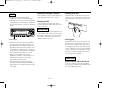
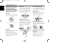
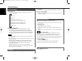
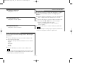
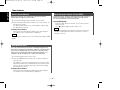
0-2)KDC-4015(K) Cover_10
00.12.29 1:50 PM
KDC-4015
KDC-415S
KDC-315V
KDC-315S
KDC-215S
KDC-35MR
Page 1
CD-RECEIVER
INSTRUCTION MANUAL
Take the time to read through this instruction manual.
Familiarity with installation and operation procedures will help
you obtain the best performance from your new CD-receiver.
For your records
Record the serial number, found on the back of the unit, in the spaces
designated on the warranty card, and in the space provided below.
Refer to the model and serial numbers whenever you call upon your
KENWOOD dealer for information or service on the product.
Model KDC-4015/415S/315V/315S/215S/35MR
Serial number
©B64-1546-10 (KW)
COMPACT
DIGITAL AUDIO
3ÅjKDC-4015(K)_U.Sr4_10
00.12.26 3:41 PM
Page 2
English
Contents
Before use
Basic Operations of remote ................................17
Warning.........................................................................................3
Safety precautions ........................................................................4
Handling Compact discs................................................................6
Installation
Accessories.................................................................................19
Installation Procedure..................................................................19
Connecting Wires to Terminals...................................................20
Installation ...................................................................................21
General features
Power............................................................................................7
Volume ..........................................................................................7
Attenuator .....................................................................................7
Switching Modes ..........................................................................8
Loudness ......................................................................................8
Audio Control Setting ....................................................................8
ec4/dB (Sound Coordinate) ...........................................................9
Mobile Preset................................................................................9
Theft Deterrent Faceplate ...........................................................10
Clock display ...............................................................................10
Adjusting Time ............................................................................10
Troubleshooting Guide .......................................24
Specifications .....................................................27
Tuner features
Tuning .........................................................................................11
Station Preset Memory ...............................................................12
Auto Memory Entry.....................................................................12
Clean Reception System Circuit (CRSC) .....................................12
CD/External disc control features
Playing CDs .................................................................................13
Playing Other Disc mode ............................................................14
Fast Forwarding and Reversing Disc Play ...................................14
Track Search................................................................................14
Disc Search .................................................................................14
Track / Disc Repeat .....................................................................15
Track Scan...................................................................................15
Disc Scan ....................................................................................15
Random Play ...............................................................................16
Magazine Random Play...............................................................16
—2—
3ÅjKDC-4015(K)_U.Sr4_10
00.12.26 3:41 PM
Page 3
2Warning
2CAUTION
Use of controls or adjustments or
performance of procedures other than those
specified herein may result in hazardous
radiation exposure.
In compliance with Federal Regulations,
following are reproductions of labels on, or
inside the product relating to laser product
safety.
KENWOOD CORPORATION
2967-3, ISHIKAWA-CHO,
HACHIOJI-SHI
TOKYO, JAPAN
KENWOOD CORP. CERTIFIES THIS EQUIPMENT
CONFORMS TO DHHS REGULATIONS N0.21 CFR
1040. 10, CHAPTER 1, SUBCHAPTER J.
Location : Bottom Panel
FCC WARNING
This equipment may generate or use radio
frequency energy. Changes or modifications
to this equipment may cause harmful
interference unless the modifications are
expressly approved in the instruction manual.
The user could lose the authority to operate
this equipment if an unauthorized change or
modification is made.
NOTE
This equipment has been tested and found to
comply with the limits for a Class B digital
device, pursuant to Part 15 of the FCC Rules.
These limits are designed to provide
reasonable protection against harmful
interference in a residential installation. This
equipment may cause harmful interference
to radio communications, if it is not installed
and used in accordance with the instructions.
However, there is no guarantee that
interference will not occur in a particular
installation. If this equipment does cause
harmful interference to radio or television
reception, which can be determined by
turning the equipment off and on, the user is
encouraged to try to correct the interference
by one or more of the following measures:
• Reorient or relocate the receiving antenna.
• Increase the separation between the
equipment and receiver.
• Connect the equipment into an outlet on a
circuit different from that to which the
receiver is connected.
• Consult the dealer or an experienced radio/TV
technician for help.
NOTE
This Class B digital apparatus complies with
Canadian ICES-003.
—3—
3ÅjKDC-4015(K)_U.Sr4_10
00.12.26 3:41 PM
Page 4
English
Safety precautions
IMPORTANT INFORMATION
2WARNING
2CAUTION
To prevent injury or fire, take the
following precautions:
To prevent damage to the machine,
take the following precautions:
• Insert the unit all the way in until it is fully
locked in place. Otherwise it may fall out of
place when jolted.
• When extending the ignition, battery, or
ground wires, make sure to use automotivegrade wires or other wires with a 0.75mm2
(AWG18) or more to prevent wire
deterioration and damage to the wire coating.
• To prevent a short circuit, never put or leave
any metallic objects (such as coins or metal
tools) inside the unit.
• If the unit starts to emit smoke or strange
smells, turn off the power immediately and
consult your Kenwood dealer.
• Make sure not to get your fingers caught
between the faceplate and the unit.
• Be careful not to drop the unit or subject it to
strong shock.
The unit may break or crack because it
contains glass parts.
• Do not touch the liquid crystal fluid if the LCD
is damaged or broken due to shock. The
liquid crystal fluid may be dangerous to your
health or even fatal.
If the liquid crystal fluid from the LCD
contacts your body or clothing, wash it off
with soap immediately.
• Make sure to ground the unit to a negative
12V DC power supply.
• Do not open the top or bottom covers of the
unit.
• Do not install the unit in a spot exposed to
direct sunlight or excessive heat or humidity.
Also avoid places with too much dust or the
possibility of water splashing.
• Do not set the removed faceplate or the
faceplate case in areas exposed to direct
sunlight, excessive heat or humidity. Also
avoid places with too much dust or the
possibility of water splashing.
• To prevent deterioration, do not touch the
terminals of the unit or faceplate with your
fingers.
• Do not subject the faceplate to excessive
shock, as it is a piece of precision equipment.
• When replacing a fuse, only use a new one
with the prescribed rating. Using a fuse with
the wrong rating may cause your unit to
malfunction.
• To prevent a short circuit when replacing a
fuse, first disconnect the wiring harness.
• Do not place any object between the
faceplate and the unit.
• Do not use your own screws. Use only the
screws provided. If you use the wrong
screws, you could damage the unit.
—4—
You cannot connect the unit directly to the
following CD automatic changers. If you want
to use older changers with the unit, follow
the directions below according to the type of
changer you own:
• KDC-C200 / KDC-C300 / KDC-C400
Use the extension cable and the control box
attached to the CD changer, and the optional
CA-DS100 converter cord.
• KDC-C301 / KDC-C600 / KDC-C800 / KDCC601 / KDC-C401
Use the extension cable attached to the CD
changer, and the optional CA-DS100
converter cord.
• KDC-C100 / KDC-C302 / C205 / C705 /
non-Kenwood CD changers
Cannot be used with this model.
2CAUTION
You can damage both your unit and
the CD changer if you connect them
incorrectly.
3ÅjKDC-4015(K)_U.Sr4_10
00.12.26 3:41 PM
Cleaning the Faceplate Terminals
NOTE
• If you experience problems during
installation, consult your Kenwood dealer.
• If the unit does not seem to be working right,
try pressing the reset button first. If that does
not solve the problem, consult your Kenwood
dealer.
SRC
PWR
OFF
SCAN
RDM
REP
D.SCN
M.RDM
AUTO
AME
CRSC
DISC
A.ADJ
LOUD
Page 5
CLK
ADJ
DISC
Reset button
If the terminals on the unit or faceplate get
dirty, wipe them with a dry, soft cloth.
Cleaning the Unit
Cleaning the CD Slot
As dust tends to accumulate in the CD slot,
clean it every once in a while. Your CDs can
get scratched if you put them in a dusty CD
slot.
If the front panel gets dirty, turn off the
power and wipe the panel with a dry silicon
cloth or soft cloth.
2CAUTION
Do not wipe the panel with a hard cloth or a
cloth dampened by volatile solvents such as
paint thinner and alcohol. They can scratch
the surface of the panel and/or cause the
indicator letters to peel off.
Lens Fogging
Right after you turn on the car heater in cold
weather, dew or condensation may form on
the lens in the CD player of the unit. Called
lens fogging, CDs may be impossible to play.
In such a situation, remove the disc and wait
for the condensation to evaporate. If the unit
still does not operate normally after a while,
consult your Kenwood dealer.
• Characters in the LCD may become difficult
to read in temperatures below 41 ˚F (5 ˚C).
• The illustrations of the display and the panel
appearing in this manual are examples used
to explain more clearly how the controls are
used. Therefore, what appears on the display
in the illustrations may differ from what
appears on the display on the actual
equipment, and some of the illustrations on
the display may represent something
impossible in actual operation.
• The functions that can be used and the
information that can be displayed will differ
depending on the external disc players being
connected.
2CAUTION
Do Not Load 3-in. CDs in the CD slot
If you try to load a 3 in. CD with its adapter
into the unit, the adapter might separate from
the CD and damage the unit.
—5—
3ÅjKDC-4015(K)_U.Sr4_10
00.12.26 3:41 PM
Page 6
English
Handling Compact discs
Playing a CD that is dirty, scratched
or warped can cause the sound to
skip and the unit to operate
incorrectly, resulting in worsened
sound quality. Take the following
precautions to prevent your CDs from
getting scratched or damaged.
Cleaning CDs
Do Not Load CD Accessories
If a CD has gotten dirty, wipe it off gently
using a commercially available cleaning cloth
or a soft cotton cloth, starting from the
center of the disc and moving outward. Do
not clean CDs with conventional record
cleaners, anti-static formulas, or chemicals
such as paint thinner or benzene.
Handling CDs
• Do not touch the recorded side of the CD
(the side opposite the label) when holding it.
Do not use commercially available CD
accessories that can be loaded into the CD
slot, such as stabilizers, protective sheets, or
CD cleaning discs, since they can cause the
unit to malfunction.
Removing the CD
Only remove the CD from the machine in a
horizontal direction, holding it flat. You may
damage the surface of the CD if you try
pulling it down as it ejects.
Checking New CDs for Burrs
• Do not stick tape on either side of the CD.
Tape
When playing a new CD for the first time,
check that there are not any burrs stuck to
the perimeter of the disc or in the central
hole. CDs with burrs stuck on them may not
load properly or may skip while playing.
Remove burrs using a ballpoint pen or a
similar utensil.
Do Not Use Special Shape CDs
• Be sure to use round shape CDs only for this
unit and do not use any special shape CDs.
Use of special shape CDs may cause the
unit to malfunction.
Burrs
• Do not store CDs in areas exposed to direct
sunlight (such as a car seat or the
dashboard) or other hot places.
• Remove CDs from the unit when not
listening to them for a while, and put them
back in their cases. Do not pile up CDs that
are removed from their cases or prop them
against something.
COMPACT
• Be sure to use CDs with disc mark
only for this unit.
Storing CDs
Burrs
DIGITAL AUDIO
Do Not Use CDs with Sticker on the
Labeled Side
Do not use the CD with the label sticker
stuck on it.
Using such a CD may cause the CD to be
deformed and the sticker to peel off,
resulting in malfunction of the unit.
—6—
3ÅjKDC-4015(K)_U.Sr4_10
00.12.26 3:41 PM
Page 7
General features
Power
SRC/
PWR OFF
FM
u
SRC
PWR
OFF
SCAN
RDM
REP
D.SCN
M.RDM
AUTO
AME
Turning on the power:
Press the SRC (source) button.
NOTE
Turn the power on before carrying out the following procedures.
Turning off the power:
Press the PWR OFF button for at least one second.
DISC
A.ADJ
LOUD
CRSC
¢
CLK
ADJ
DISC
Volume
d
ATT/
LOUD
#1-5
AUD/ 4
A.ADJ
CLK
AM
Increasing Volume:
Press the u button to turn up the volume.
Decreasing Volume:
Press the d button to turn down the volume.
Attenuator
ATT indicator
This function allows you to turn down the volume quickly.
Turning Attenuator On/Off:
Press the ATT button to switch the attenuator on and off.
When the attenuator is on, the ATT indicator blinks.
When the attenuator is off, the volume returns to the original
level.
NOTE
Turning the volume up, or turning it all the way down deactivates
the attenuator function.
LOUD indicator
—7—
3ÅjKDC-4015(K)_U.Sr4_10
00.12.26 3:41 PM
Page 8
English
General features
Switching Modes
Switching Modes:
Each time you press the SRC (source) button, the mode
switches as follows:
turned down.
The LOUD indicator lights up when the loudness function is on.
Turning Loudness On/Off:
Press the LOUD button for at least one second to switch the
loudness on and off.
▼
Tuner mode
▼
CD mode
▼
External disc control mode 1
(KDC-4015/415S/315V/315S/35MR only)
▼
External disc control mode 2/AUX mode
(KDC-4015/415S/315V/315S/35MR only)
▼
Standby mode
Selecting standby mode:
Press the SRC button repeatedly and switch to "OFF"
When "OFF" is displayed, the standby mode is activated.
The standby mode turns all functions off while leaving the
power to the unit on. Use this mode when you want to have
the display illuminated but don't want to listen to anything.
NOTE
• The mode switches to the next mode from any mode which
cannot be used.
• The external disc control mode will differ depending on the unit
that is connected.
• The AUX mode is available only when the changer / AUX
switching adapter (KCA-S210A or CA-C1AX) or CD changer
(KDC-CPS85, KDC-CX85, KDC-CPS82 or KDC-CX82) is
connected to this unit.
During the AUX mode, "AVin" will show in the display.
When the CA-C1AX is being used, the AUX Mode will replace
the External Disc Control Mode.
Loudness
Audio Control Setting
Adjust various parameters of sound quality.
1 Press the A.ADJ button for at least one second to enter the
control mode.
2 Selecting mode
Press either the FM or AM button.
Each time the button is pressed, the adjustment mode will
change.
Please refer to the following for the contents of the adjustment
modes.
NOTE Source tone memory
Each source ( CD, FM, AM and disc changer ) has its own
memory in which to store the bass and treble tone settings.
The settings made for a particular source are recalled
automatically whenever you use that source ( for example, FM
mode uses the tone settings made for FM, AM for AM, etc.).
3 Adjust each mode
Press the 4/¢ button.
Please refer to the following for the adjusting values.
4 Press the A.ADJ button to end the control mode.
"BAS": Adjust the bass level.
Setting values: - 8 - + 8
This function amplifies low and high tones when the volume is
—8—
3ÅjKDC-4015(K)_U.Sr4_10
00.12.26 3:41 PM
Page 9
Function of the KDC-4015
"TRE": Adjust the treble level.
Setting values: - 8 - + 8
Mobile Preset
This function allows you to adjust the setting that is recalled
with the sound coordinate system, according to types of
speakers.
1 Press the SRC button repeatedly to select the standby mode.
"BL": Adjust the balance level.
Setting values: Left 15 - Right 15
“OFF” is displayed when the standby mode is selected.
2 Press the AUD button to enter the mobile preset plan mode.
3 Press either the 4 or ¢ button to select the type of
speaker. The setting switches as follows.
Flat / For the OEM speaker / For 6x9 in. speaker /
For 5 in. speaker
"FD": Adjust the fader level.
Setting values: Front 15 - Rear 15
4 Press the AUD button to end the mobile preset plan mode.
NOTE
When you change the setting of type of speaker, the bass and
treble tone settings are returned to original levels.
ec4/dB (Sound Coordinate)
You can recall the best audio setting preset for different types
of the music.
1 Press the AUD button to enter the Sound Coordinate mode.
2 Press a preset button (#1-5).
The preset settings of the bass and treble tones are recalled.
#1: Flat
#2: Rock
#3: Top 40
#4: Jazz
#5: Easy
3 Press the AUD button to end the sound coordinate mode.
NOTE
You can call the following settings with this function; bass center
frequency, bass level, bass quality factor, bass extension, treble
center frequency, and treble level setting.
—9—
3ÅjKDC-4015(K)_U.Sr4_10
00.12.26 3:41 PM
Page 10
English
General features
Theft Deterrent Faceplate
Clock display
The faceplate of the unit can be detached and taken with you,
helping to deter theft.
Turning clock display On/Off:
Press the CLK button to switch the clock display on and off.
The £ indicator lights while the clock is displayed.
Projections
Release button
Grooves
Adjusting Time
Removing the Faceplate:
Press the release button.
The faceplate is unlocked, allowing you to detach it.
Adjust the time.
1 When the time is not displayed, first press the CLK button to
display the time.
NOTE
• The faceplate is a precision piece of equipment and can be
damaged by shocks or jolts. For that reason, keep the faceplate
in its special storage case while detached.
• Do not expose the faceplate or its storage case to direct
sunlight or excessive heat or humidity. Also avoid places with
too much dust or the possibility of water splashing.
Reattaching the Faceplate:
1 Align the projections on the unit with the grooves on the
faceplate.
2 Press the CLK button for at least two seconds to enter the
clock adjustment mode. The time display will blink.
3 • Adjusting the hours
Press the FM button to advance the hours, or press the AM
button to make the hours go back.
• Adjusting the minutes
Press the ¢ button to advance the minutes, or press the
4 button to make the minutes go back.
4 Press the CLK button to end the clock adjustment mode.
2 Push the faceplate in until it clicks.
The faceplate is locked in place, allowing you to use the unit.
— 10 —
3ÅjKDC-4015(K)_U.Sr4_10
00.12.26 3:41 PM
Page 11
Tuner features
Tuning
FM/
CRSC
¢
SRC
You can choose between auto seek tuning of receivable
frequencies and manual tuning.
1 Press the SRC (source) button repeatedly to select the tuner
mode. "TUnE" is displayed when the tuner mode has been
selected.
SRC
PWR
OFF
LOUD
SCAN
RDM
REP
D.SCN
M.RDM
AUTO
AME
CRSC
2 Press either the FM or AM button to select the band.
Each time you press the FM button, the band switches
between FM1, FM2, and FM3 (which are used for groups of
preset stations).
Press the AM button to select the AM band.
DISC
A.ADJ
CLK
ADJ
DISC
3 Press the AUTO button to switch between auto seek tuning
4
#1-6
AUTO/
AME
and manual tuning.
The AUTO indicator lights up only when auto seek tuning is
selected.
AM
4 • Auto Seek Tuning
Press the ¢ button
Press the 4 button
• Manual Tuning
Press the ¢ button
Press the 4 button
ST indicator
Band display
indicator
Frequency
Preset station number
to seek higher frequencies.
to seek lower frequencies.
to increase the frequency by one step.
to decrease the frequency by one step.
NOTE
The ST indicator lights up when stereo broadcasts are being
received.
AUTO indicator
— 11 —
3ÅjKDC-4015(K)_U.Sr4_10
00.12.26 3:41 PM
Page 12
English
Tuner features
Station Preset Memory
Clean Reception System Circuit (CRSC)
Store the frequency of a station. You can then recall that
station with a single touch of a button.
Temporarily have reception switched from stereo to mono to
reduce multi-path noise when listening to the FM station.
The factory default for this function is ON.
1 Select the band/ station that you want to have stored.
2 Press the button (#1-6) that you want to use for the station, for
Turning CRSC On/Off:
Press the CRSC button for at least one second to turn the
function on/off.
The
indicator lights up when CRSC is on.
at least two seconds.
The button number blinks once in the display to indicate that
the data has been stored.
Recalling a Preset Station:
Press the preset station button (#1-6) for the desired station.
The number of the recalled station is displayed.
NOTE
Strong electrical fields (such as from power lines) may cause
unstable sound quality when CRSC is turned on. In such a
situation, turn it off.
NOTE
You can store six stations in each of the FM1, FM2, FM3, and AM
bands.
Auto Memory Entry
You can automatically store all the receivable frequencies in
the band currently being listened to, and then recall them with
the touch of a button later. This function is especially useful
when you are travelling and do not know what stations are
available. Up to six frequencies can be stored this way.
1 Select the band for auto memory entry.
2 Press the AME button for at least two seconds to start auto
memory entry.
The numbers of the preset station buttons are shown in order.
When all the stations in a certain band are stored in the preset
memory, the auto memory entry stops. The tuner then plays
the last station received.
Recalling a Preset Station:
Press the preset station button (#1-6) for the desired station.
The number of the recalled station is displayed.
— 12 —
3ÅjKDC-4015(K)_U.Sr4_10
00.12.26 3:41 PM
Page 13
CD/External disc control features
Playing CDs
DISC +
0
¢
SRC
SRC
PWR
OFF
LOUD
SCAN
RDM
SCAN
REP
REP
RDM
M.RDM
D.SCN
AUTO
AME
CRSC
DISC
A.ADJ
CLK
ADJ
DISC
4
M.RDM
2CAUTION
DISC -
D.SCN
Disc number
Track number
Playing CDs:
If no CDs are inserted, insert one in the slot with the label
facing up.
If a CD is already inserted, press the SRC button repeatedly to
select the CD mode.
"CD" is displayed when the CD mode has been selected.
The CD will start playing.
The CD-IN indicator lights up when a CD has been inserted.
The 3 indicator lights up when a CD is being played.
Stopping and Ejecting CDs:
Press the 0 button.
The CD stops playing and ejects from the slot.
Track time
• Do not attempt to insert a CD into the slot if another one is
already there.
• The unit can only play 5 in. CDs. If you insert a 3 in. CD, it will
get stuck inside and can cause the unit to malfunction.
NOTE
When you load a CD and eject it right away, the next time you try
to insert the CD may not load. In such a situation, take the CD out
for a moment and then reinsert it.
REP indicator
SCN indicator
3 indicator
CD-IN indicator
RDM indicator
When the disc changer with the O-N selection switch is
connected, set the switch to "N" position to operate the
external disc control mode.
— 13 —
3ÅjKDC-4015(K)_U.Sr4_10
00.12.26 3:41 PM
Page 14
English
CD/External disc control features
Function of the KDC-4015/KDC-415S/KDC-315V/KDC-315S/KDC-35MR
Playing Other Disc mode
Track Search
Search forward or backward through the tracks on the disc until
you reach the one that you want to listen to.
This function permits the connection of optional players and
the playing of discs other than the loaded CD (in the current
unit).
Making a Reverse Track Search:
Press the 4 button to display the desired track number.
Press once to search back to the beginning of the current track,
twice to search back to the beginning of the previous track, and
so forth.
Play starts at the beginning of the displayed track number.
Playing Discs:
Press the SRC button repeatedly to select the external disc
control mode.
The disc will start playing.
NOTE
NOTE
The external disc control mode will differ, depending on the unit
that is connected.
Mode Display Examples
• "CD2"...when a CD player is connected
• "DISC"...when a disc changer is connected
• "DISC-1", "DISC-2"...when two disc changers are connected
NOTE
• When one disc has finished playing its last track, the next disc in
the changer will start playing. When the last disc in the changer
has finished, the player will return to the first disc and start
playing it.
• Disc #10 is displayed as "0".
(For disc changers : KDC-4015/KDC-415S/KDC-315V/
KDC-315S/KDC-35MR only)
Pressing the 4 button while listening to track 1 will only search
back to the beginning of that track. The reverse search is not
"recycled" to the last track on the disc.
Making a Forward Track Search:
Press the ¢ button to display the desired track number.
Press once to fast forward to the next track, twice to fast
forward to the track after that, and so forth.
Play starts at the beginning of the displayed track number.
NOTE
(For disc changers: KDC-4015/KDC-415S/KDC-315V/
KDC-315S/KDC-35MR only)
You cannot make a forward track search when listening to the last
track on a disc.
Fast Forwarding and Reversing Disc Play
Fast Forwarding Disc Play:
Hold down on the ¢ button.
Release your finger to play the disc at that point.
Reversing Disc Play:
Hold down on the 4 button.
Release your finger to play the disc at the point.
NOTE
You cannot use reverse play between tracks depending on the
model being connected. Instead, the reverse play function is
canceled when it reaches the beginning of a track, at which point
normal play will automatically resume.
Function of the KDC-4015/KDC-415S/KDC-315V/KDC-315S/KDC-35MR
Disc Search
(Function of disc changers)
Search forward or backward through the discs in a disc
changer.
Making a Reverse Disc Search:
Press the DISC– button to display the desired disc number.
Each time the button is pressed, the displayed disc number
decreases by one.
Play starts at the beginning of the displayed disc.
— 14 —
3ÅjKDC-4015(K)_U.Sr4_10
00.12.26 3:41 PM
Page 15
Making a Forward Disc Search:
Press the DISC + button to display the desired disc number.
Each time the button is pressed, the displayed disc number
increases by one.
Play starts at the beginning of the displayed disc.
NOTE
"LOAd" is displayed when discs are being exchanged on the disc
changer.
Starting the Track Scan :
Press the SCAN button. The SCN indicator lights up and the
first 10 seconds of each track will be played, in order.
The track number currently being heard blinks in the display.
Stopping to Listen to the Track Being Scanned:
Press the SCAN button again to stop the scan and keep on
listening to a track normally.
NOTE
• The track scan function is canceled when you eject the disc.
• The track scan function only scans each track on a disc once.
Track / Disc Repeat
Repeat playing the track or the disc currently being listened to.
Turning Repeat Play On/Off:
Press the REP button to switch repeat track/disc play on and
off as follows:
Function of the KDC-4015/KDC-415S/KDC-315V/KDC-315S/KDC-35MR
Disc Scan
(Function of disc changers)
Successively play the beginning of each disc on a changer until
you find the one that you want to listen to.
▼
Track Repeat ON
▼
Disc Repeat ON (Function of disc changers :
KDC-4015/415S/315V/315S/35MR only)
▼
Track/Disc Repeat OFF
The REP indicator lights up when repeat play is turned on.
The track number blinks in the display when track repeat is on.
The disc number blinks in the display when disc repeat is on.
NOTE
Repeat play is canceled when you eject the disc.
Starting the disc scan:
Press the D.SCN button. The SCN indicator lights up and the
first 10 seconds of each disc will be played, in the order they
are loaded on the changer.
The disc number currently being heard blinks in the display.
Stopping to Listen to the Disc Being Scanned:
Press the D.SCN button again to stop the scan and keep on
listening to the disc normally.
NOTE
• The disc scan function is canceled when you eject the disc.
• The disc scan function only scans each disc on the changer
once.
• "LOAd" is displayed when discs are being exchanged on the disc
changer.
Track Scan
Successively play the beginning of each track on a disc until
you find the track that you want to listen to.
— 15 —
3ÅjKDC-4015(K)_U.Sr4_10
00.12.26 3:41 PM
Page 16
English
CD/External disc control features
Random Play
NOTE
This function is not available with the following models:
KDC-C200/C300/C400/C301/C401
Play all the tracks on the current disc in random order.
1 Press the RDM button to switch random play on and off.
2 To change the track being heard, press the ¢ button.
The RDM indicator lights up when random play is turned on.
The track number will change over and over in the display as
the next track is being selected.
When the track has been selected, play will begin.
The selected track number blinks in the display as it is being
played.
Another disc/track will be selected and played.
NOTE
• Magazine random play is canceled when you eject the disc.
• The time needed for random selection depends on the number
of discs loaded in the disc magazine.
NOTE
(For disc changers : KDC-4015/KDC-415S/KDC-315V/
KDC-315S/KDC-35MR only)
When all the tracks on a certain disc have been played using
random play, the next disc on the changer will start playing using
the same function.
2 To change the track being heard, press the ¢ button.
Another track will be selected and played.
NOTE
Random play is canceled when you eject the disc.
Function of the KDC-4015/KDC-415S/KDC-315V/KDC-315S/KDC-35MR
Magazine Random Play
(Function of disc changers)
Play the tracks on all the discs in the disc changer in random
order.
1 Press the M.RDM button to switch magazine random play on
and off.
The RDM indicator lights up when magazine random play is
turned on.
The disc and track numbers will change over and over in the
display as the next track is being selected.
When the disc/track has been selected, play will begin.
The selected disc/ track number blinks in the display as it is
being played.
— 16 —
3ÅjKDC-4015(K)_U.Sr4_10
00.12.26 3:41 PM
Page 17
Basic Operations of remote
Accessory of the KDC-4015/415S/315V
NOTE
The supplied remote control unit is in its storage case.
2CAUTION
+
–
FM/DISC +
+
-
4
FM
ATT
+
ATT
AM/DISC –
SRC
¢
TUNE
TRACK
DISC
AM
–
DNPP/
SBF
38
SRC
TUNE –/4/TRACK –
TUNE +/¢/TRACK +
Do not set the remote on hot places such as above the
dashboard.
Loading and Replacing the Batteries:
Use two “AAA”-size batteries.
Slide the cover while pressing downwards to remove it as
illustrated.
Insert the batteries with the + and – poles aligned properly,
following the illustration inside the case.
38
OK
2WARNING
Store unused batteries out of the reach of children. Contact a
doctor immediately if the battery is accidentally swallowed.
NOTE
REMOTE CONTROL UNIT
• The provided batteries are intended for use in operation
checking, and their service life may be short.
• When the remote controllable distance becomes short, replace
both of the batteries with new ones.
• When A portion of the operations may not be possible,
depending on the unit that is connected.
— 17 —
3ÅjKDC-4015(K)_U.Sr4_10
00.12.26 3:41 PM
Page 18
Basic Operations of remote
English
Accessory of the KDC-4015/415S/315V
Basic operations
• VOLUME buttons
Press the + button to turn the volume up.
Press the – button to turn the volume down.
• SRC button
Each time you press the SRC button, the mode switches as
follows:
▼
Tuner features
• 4/¢ (TUNE) buttons
Press the 4 button to decrease the frequency.
Press the ¢ button to increase the frequency.
• AM/FM button
Press the AM button to select the AM band.
Press the FM button to select and switch between FM1, FM2,
and FM3 bands.
Tuner mode
▼
CD mode
▼
External disc control mode 1
(KDC-4015/415S/315V/315S/35MR only)
▼
External disc control mode 2/AUX mode
(KDC-4015/415S/315V/315S/35MR only)
▼
Standby mode
NOTE
• The mode switches to the next mode from any mode which
cannot be used.
• The external disc control mode will differ depending on the unit
that is connected.
• The AUX mode is available only when the changer / AUX
switching adapter (KCA-S210A or CA-C1AX) or CD changer
(KDC-CPS85, KDC-CX85, KDC-CPS82 or KDC-CX82) is
connected to this unit.
During the AUX mode, "AVin" will show in the display.
When the CA-C1AX is being used, the AUX Mode will replace
the External Disc Control Mode.
• ATT button
Turns down the volume quickly. To return the volume to its
original level, press the button again. Turning the volume up, or
turning it all the way down deactivates the attenuator function.
CD/External disc control features
• 4/¢ buttons
Press the 4 button to search through the tracks backward.
Press the ¢ button to search through the tracks forward.
• DISC buttons (for disc changers)
Press the DISC– button to search through the discs backward.
Press the DISC+ button to search through the discs forward.
• 38 button
When a disc is playing, this button pauses the play.
Press the same button again to start play again.
— 18 —
3ÅjKDC-4015(K)_U.Sr4_10
00.12.26 3:41 PM
Page 19
Accessories
External view
Installation Procedure
Number of items
1
..........................................1
2
..........................................1
3
..........................................2
1. To prevent a short circuit, remove the key from the ignition and
disconnect the - battery.
2. Make the proper input and output wire connections for each unit.
3. Connect the speaker wires of the wiring harness.
4. Connect the wiring harness wires in the following order: ground,
battery, ignition.
5. Connect the wiring harness connector to the unit.
6. Install the unit in your car.
7. Reconnect the - battery.
8. Press the reset button.
2CAUTION
4
..........................................1
5
..........................................4
6
..........................................4
7
..........................................1
2CAUTION
The use of any accessories except for those provided might
result in damage to the unit. Make sure only to use the
accessories shipped with the unit, as shown above.
• If your car's ignition does not have an ACC position, connect
the ignition wires to a power source that can be turned on and
off with the ignition key. If you connect the ignition wire to a
power source with a constant voltage supply, as with battery
wires, the battery may die.
• If the console has a lid, make sure to install the unit so that the
faceplate will not hit the lid when closing and opening.
• If the fuse blows, first make sure the wires aren’t touching to
cause a short circuit, then replace the old fuse with one with
the same rating.
• Do not let unconnected wires or terminals touch metal on the
car or anything else conducting electricity. To prevent a short
circuit, do not remove the caps on the ends of the unconnected
wires or the terminals.
• Connect the speaker wires correctly to the terminals to which
they correspond. The unit may be damaged or fail to work if you
share the - wires or ground them to any metal part in the car.
• After the unit is installed, check whether the brake lamps,
blinkers, wipers, etc. on the car are working properly.
• Insulate unconnected wires with vinyl tape or other similar
material.
• Some disc changers need conversion cords for connection. See
the section on "Safety Precautions" for details.
• Mount the unit so that the mounting angle is 30° or less.
— 19 —
3ÅjKDC-4015(K)_U.Sr4_10
00.12.26 3:41 PM
Page 20
Connecting Wires to Terminals
English
KENWOOD disc changer control input (KDC-4015/415S/315V/315S/35MR only)
NOTE
Rear left output (White)
Front left output (White)
(KDC-4015/415S only)
Fuse (10A)
To connect the Disc changer,
consult your Disc changer manual.
Front right output (Red)
(KDC-4015/415S only)
FM/AM antenna input
If no connections are made, do not let the
wire come out from the tab.
Rear right output (Red)
Wiring harness
(Accessory1)
White/Black
FRONT • L
White
Connect either to the power control terminal
when using the optional power amplifier, or to
the antenna control terminal in the vehicle.
P.CONT.OUT
ANT.
CONT.
Gray/Black
Power control/Motor antenna
control wire (Blue/White)
FRONT • R
Gray
Green/Black
Ignition key
switch
ACC
REAR • L
Green
–
+
To front left
speaker
–
To front right
+ speaker
–
+
To rear left
speaker
Ignition wire (Red)
Purple/Black
Battery wire (Yellow)
Car fuse box
(Main fuse)
Car fuse
box
REAR • R
Purple
–
+
To rear right
speaker
Ground wire (Black) · (To car chassis)
Battery +
–
2CAUTION
2WARNING
If you connect the ignition wire (red) and the battery wire
(yellow) to the car chassis (ground), you may cause a short
circuit, that in turn may start a fire. Always connect those wires
to the power source running through the fuse box.
— 20 —
When only two speakers are being connected to the system,
connect the connectors either to both the front output
terminals or to both the rear output terminals (do not mix
front and rear). For example, if you connect the + connector
of the left speaker to a front output terminal, do not connect
the - connector to a rear output terminal.
3ÅjKDC-4015(K)_U.Sr4_10
00.12.26 3:41 PM
Page 21
Installation
■ Installing in Japanese-Made Cars
■ Installation
1 Refer to the section “Removing the hard rubber frame (P. 22)”
Firewall or metal support
and then remove the hard rubber frame.
2 Align the holes in the unit (two locations on each side) with the
vehicle mounting bracket and secure the unit with the
accessory screws.
Accessory4
T
N
8 mm
MAX.
N
Self-tapping
screw
(commerciall
y available)
Accessory2
Metal mounting
strap
Bend the tabs of the
mounting sleeve with
a screwdriver or
similar utensil and
attach it in place.
NOTE
Make sure that the unit is installed securely in place. If the unit is
unstable, it may malfunction (for example, the sound may skip).
T
T/N
ø5mm
T: Toyota cars
N: Nissan cars
8mm
MAX.
5
6
ø5mm
Accessory5...for Nissan car
Accessory6 ...for Toyota car
2CAUTION
• During installation, do not use any screws except for those
provided. The use of different screws might result in damage to
the main unit.
• Damage may occur if a screwdriver or similar tool is used with
excessive force during the installations.
— 21 —
3ÅjKDC-4015(K)_U.Sr4_10
00.12.26 3:41 PM
Page 22
English
Installation
■ Removing the hard rubber frame
■ Removing the Unit
1 Engage the catch pins on the removal tool and remove the two
1 Refer to the section “Removing the hard rubber frame (P. 22)”
locks on the lower level.
Lower the frame and pull it forward as shown in the figure.
and then remove the hard rubber frame.
2 Remove the Hex-head screw with integral washer (M4×8) on
the back panel.
Catch
3 Insert the two removal tools deeply into the slots on each side,
as shown.
Lock
Accessory4
Catch facing up
Accessory3
Removal tool
2 When the lower level is removed, remove the upper two
locations.
Accessory3
Removal tool
4 Lower the removal tool
toward the bottom, and pull
out the unit halfway whilst
pressing towards the
inside.
2CAUTION
NOTE
The frame can be removed from the top side in the same
manner.
Be careful to avoid injury from the catch pins on the removal
tool.
5 Pull the unit all the way out
with your hands, being
careful not to drop it.
— 22 —
3ÅjKDC-4015(K)_U.Sr4_10
00.12.26 3:41 PM
Page 23
■ Screwing the Faceplate on the Unit
If you want to fasten the faceplate to the main unit so that it
does not fall off, screw in the provided screw (ø4 × 16 mm) in
the hole shown below.
Accessory7
2CAUTION
Never insert the taptite screw (ø4 × 16 mm) in any other screw
hole than the one specified. If you screw it in another hole, it will
contact and may cause damage to the mechanical parts inside
the unit.
— 23 —
3ÅjKDC-4015(K)_U.Sr4_10
00.12.26 3:41 PM
Page 24
Troubleshooting Guide
English
What might seem to be a malfunction in your unit may just be the result of slight misoperation or miswiring.
Before calling service, first check the following table for possible problems.
PROBLEM
POSSIBLE CAUSE
SOLUTION
The power does not turn on.
The fuse has blown.
After checking for short circuits in the wires, replace the
fuse with one with the same rating.
No sound can be heard, or the
volume is low.
Attenuator is turned on.
Turn off Attenuator.
The fader or balance settings are set all the way to one
side.
Reset the fader or balance settings.
The input/output wires or wiring harness are connected
incorrectly.
Reconnect the input/output wires or the wiring harness
correctly. See the section on "Connecting Wires to
Terminals".
Nothing happens when the
buttons are pressed.
The computer chip in the unit is not functioning normally.
Press the reset button on the unit (see p. 5).
The sound quality is poor or
distorted.
One of the speaker wires is being pinched by a screw in
the car.
Check the speaker wiring.
The speakers are not wired correctly.
Reconnect the speaker wires so that each output
terminal is connected to a different speaker.
The car antenna is not extended.
Pull the antenna out all the way.
The antenna control wire is not connected.
Connect the wire correctly, referring to the section on
"Connecting Wires to Terminals".
The battery wire has not been connected to the proper
terminal.
Connect the wire correctly, referring to the section on
"Connecting Wires to Terminals".
The ignition and battery wire are incorrectly connected.
Connect the wire correctly, referring to the section on
"Connecting Wires to Terminals".
The CD is upside-down.
Load the CD with the labeled side up.
The CD is quite dirty.
Clean the CD, referring to the section on "Cleaning CDs"
(see p. 6).
The sound skips on a CD.
The CD is scratched or dirty.
Clean the CD, referring to the section on "Cleaning CDs"
(see p. 6).
A track will not play.
Random play has been selected.
Turn off random play.
Radio reception is poor.
The memory is erased when
the ignition is turned off.
A CD ejects as soon as it is
loaded.
— 24 —
3ÅjKDC-4015(K)_U.Sr4_10
00.12.26 3:41 PM
Page 25
External disc control mode (KDC-4015/KDC-415S/KDC-315S/KDC-35MR only)
PROBLEM
POSSIBLE CAUSE
SOLUTION
The disc control mode cannot
be selected.
No wire has been connected to the disc changer input
terminal on the unit.
Connect the wire to the disc changer input terminal on
the unit.
The specified disc does not
play, but another one plays
instead.
The specified CD is quite dirty.
Clean the CD.
The CD is upside-down.
Load the CD with the labeled side up.
The disc is loaded in a different slot from that specified.
Eject the disc magazine and check the number for the
specified disc.
The disc is severely scratched.
Try another disc instead.
Something is touching the disc changer.
Remove whatever is touching it.
The CD is scratched or dirty.
If skipping happens at the same place when the car is
stopped, something with the CD is wrong. Clean the CD.
The display shows that the
changer is being played, but no
sound can be heard.
The computer chip in the unit is not functioning normally.
Press the reset button on the unit (see p. 5).
The specified track will not
play.
Random play or magazine random play has been selected.
Turn off random play or magazine random play.
The sound skips.
If the following situations, consult your nearest service center:
• Even though the disc changer is connected, the Disc Changer Mode is not on, with "AVin" showing in the display during the Changer Mode.
• Even though no device (KCA-S210A, CA-C1AX, KDC-CPS85, KDC-CX85, KDC-CPS82 or KDC-CX82) is connected, the AUX Mode is entered
when switching modes.
— 25 —
3ÅjKDC-4015(K)_U.Sr4_10
00.12.26 3:41 PM
Page 26
English
Troubleshooting Guide
The following messages are displayed when certain problems are occurring in your system. Take the
recommended actions.
E-01
No disc magazine has been loaded in the changer. The disc magazine is not completely loaded.
] Load the disc magazine properly.
No CD in the unit.
] Insert the CD.
E-02
No disc has been loaded in the disc magazine.
] Load a disc into the disc magazine.
E-04
No disc has been loaded in the disc magazine.
] Load a disc into the disc magazine.
The CD is quite dirty. The CD is upside-down. The CD is scratched a lot.
] Clean the CD and load it correctly.
E-10
Nothing has been recorded on the MD.
] The next MD will automatically be played.
E-11
No tracks are recorded on the MD, although it has a title.
] The next MD will automatically be played.
E-30
The faceplate of the slave unit being connected to this unit has been removed.
] Replace it.
E-77
The unit is malfunctioning for some reason.
] Press the reset button on the unit. If the "E- 77" code does not disappear, consult your nearest service center.
E-99
Something is wrong with the disc magazine. Or the unit is malfunctioning for some reason.
] Check the disc magazine. And then press the reset button on the unit. If the "E- 99" code does not disappear, consult your
nearest service center.
E-0d
The protective circuit in the unit activates when the temperature inside the automatic disc changer exceeds 60°C (140°F),
stopping all operation.
] Cool down the unit by opening the windows or turning on the air conditioner. As the temperature falls below 60°C (140°F),
the disc will start playing again.
— 26 —
3ÅjKDC-4015(K)_U.Sr4_10
00.12.26 3:41 PM
Page 27
Specifications
Specifications subject to change without notice.
FM tuner section
Audio section
Frequency range (200 kHz space) .............87.9 MHz – 107.9 MHz
Usable sensitivity (S/N = 30dB).....................9.3dBf (0.8 µV/75 Ω)
Quieting Sensitivity (S/N = 50dB) ................15.2dBf (1.6 µV/75 Ω)
Frequency response (±3.0 dB) ..............................30 Hz – 15 kHz
Signal to Noise ratio (MONO) ..............................................70 dB
Selectivity (±400 kHz) .......................................................≥ 80 dB
Stereo separation (1 kHz).....................................................40 dB
AM tuner section
Maximum output power .................................................45 W × 4
Full bandwidth power (at less than 1% THD)..................22 W × 4
Tone action
Bass: ...........................................................100 Hz ±10 dB
Treble: .........................................................10 kHz ±10 dB
Preout level / Load..................................................1800mV/10kΩ
Preout impedance ............................................................≤ 600 Ω
General
Frequency range (10 kHz space) ....................530 kHz – 1700 kHz
Usable sensitivity (S/N = 20dB) .............................28 dBµ (25 µV)
CD player section
Laser diode ....................................................GaAlAs (λ=780 nm)
Digital filter (D/A)......................................8 Times Over Sampling
D/A Converter .......................................................................1 Bit
Spindle speed ...............................................500 – 200 rpm (CLV)
Wow & Flutter ........................................Below Measurable Limit
Frequency response (±1 dB) .................................10 Hz – 20 kHz
Total harmonic distortion (1 kHz) ......................................0.01 %
Signal to Noise ratio.................................................96 dB (1 kHz)
Dynamic range ....................................................................93 dB
Channel separation ..............................................................85 dB
Operating voltage ..............................14.4 V (11 – 16 V allowable)
Current consumption .............................................................10 A
Installation size (W × H × D) ...........................182 × 53 × 160 mm
7-3/16 × 2-1/16 × 6-1/4 in.
Weight..................................................................3.1 Lbs (1.4 kg)
— 27 —
3ÅjKDC-4015(K)_U.Sr4_10
00.12.26 3:41 PM
Page 28