1
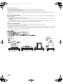
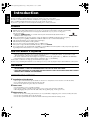
VS-DT2000[US-UW]_Cover1.FM Page 1 Friday, March 8, 2002 3:11 PM
COMPACT COMPONENT SYSTEM
SISTEMAS DE COMPONENTES COMPACTOS
SISTEMA DE COMPONENTES COMPACTOS
VS-DT2000
Consists of CA-VSDT2000, SP-VSDT2000 and SP-PW2000
Consiste de CA-VSDT2000, SP-VSDT2000 y SP-PW2000
Consiste em CA-VSDT2000, SP-VSDT2000 e SP-PW2000
CA-VSDT2000 SP-VSDT2000 SP-PW2000
COMPACT COMPONENT SYSTEM
STANDBY/ON
1
2
3
4
5
6
PLAY MODE
REPEAT
7
9
8
FM MODE
10
+10
BASS
TREBLE
SET
CANCEL
MD/AUX
FM/AM
DISPLAY
DIMMER
COLOR
CLOCK
/TIMER
OPEN/
CLOSE
SLEEP
VOLUME
SP-VSDT2000
CA-VSDT2000
SP-VSDT2000
INSTRUCTIONS
MANUAL DE INSTRUCCIONES
INSTRUÇÕES
SP-PW2000
For Customer Use:
Enter below the Model No. and Serial No.
which are located either on the rear, bottom or side of the cabinet. Retain this
information for future reference.
Model No.
Serial No.
LVT0854-004A
[US, UW]
VS-DT2000[US-UW]_Warning.fm
Page 1
Thursday, April 4, 2002
4:34 PM
Warnings, Cautions and Others
Avisos, precauciones y otras notas
Advertências, precauções e outras notas
CAUTION
To reduce the risk of electrical shocks, fire, etc.:
1. Do not remove screws, covers or cabinet.
2. Do not expose this appliance to rain or moisture.
PRECAUCIÓN
Para reducir riesgos de choques eléctricos, incendio, etc.:
1. No extraiga los tornillos, los cubiertas ni la caja.
2. No exponga este aparato a la lluvia o a la humedad.
PRECAUÇÃO
Para reduzir riscos de choques elétricos, incêndio, etc.:
1. Não remova parafusos e tampas ou desmonte a caixa.
2. Não exponha este aparelho à chuva nem à umidade.
Caution — % switch! (CA-VSDT2000)
Disconnect the mains plug to shut the power off completely
(the % goes off).
The % switch in any position does not disconnect the mains
line.
• When the unit is on standby, the % lights red.
• When the unit is turned on, the operation lamps light red.
The power can be remote controlled.
Precaución — Conmutador %! (CA-VSDT2000)
Desconectar el enchufe de la red para desconctar la alimentación por completo (la lámpara % se apaga).
El conmutador % no desconectará completamente la alimentación principal, cualquiera que sea su posición.
• Cuando la unidad está en espera, la lámpara % se enciende
en rojo.
• Cuando conecta la unidad, la lámpara de operación se
enciende en rojo.
La alimentación puede ser controlada a distancia.
Cuidado — Interruptor %! (CA-VSDT2000)
Desconecte o plugue da tomada para desligar completamente
(o % se apaga).
Nenhuma posição do interruptor % desliga a alimentação.
• Quando o aparelho está em espera, o % se acende em
vermelho.
• Quando o aparelho está ligado, as indicações de operação
se acendem em vermelho.
A alimentação pode ser remotamente controlada.
注意 - % 开关 ! (CA-VSDT2000)
拨下电源插头来完全切断电源 (% 熄灭 )。
% 开关位于任何位置均不能切断电源。
• 当本机处于待机状态时, % 将点亮呈红色。
• 当本机打开时,操作指示灯将点亮呈红色。
电源可以遥控操作。
G-1
Cauation — POWER switch! (SP-PW2000)
This apparatus is provided with a POWER switch to be able to
minimize power consumption for safe use. Therefore,
1. When doing initial setting, complete all the connections
required, connect the mains plug into the wall outlet, and
set the POWER switch to ON.
2. When not in use, set the POWER switch to OFF.
3. Disconnect the mains plug to shut the power off completely. The POWER switch in any position do not disconnect the mains line.
Precaución — Conmutador POWER! (SP-PW2000)
Este aparato está provisto de un conmutador POWER capaz
de reducir el consumo de energía al mínimo para un uso seguro. Por consiguiente,
1. Cuando realice los ajustes iniciales, efectúe todas las conexiones requeridas, conecte el enchufe de la red en el
tomacorriente de pared, y ajuste el conmutador POWER a
ON.
2. Cuando no esté en uso, ajuste el conmutador POWER a
OFF.
3. Extraiga el enchufe del tomacorriente para desconectar la
alimentación por completo. La línea de la red no se
desconecta en ninguna de las posiciones del conmutador
POWER.
Cuidado — Interruptor POWER! (SP-PW2000)
Este equipamento é fornecido com um interruptor POWER de
alimentação para poder minimizar o consumo de energia para
uso com segurança. Portanto,
1. quando fazendo os ajustes iniciais, complete todas as
conexões necessárias, ligue o plugue na tomada de
parede e, então, coloque o interruptor POWER em ON.
2. Quando não estiver usando o aparelho, coloque o
interruptor POWER em OFF.
3. Desconecte o plugue da tomada para desligar a
alimentação completamente. Nenhuma posição do
interruptor POWER desliga a alimentação.
注意 - POWER 开关 ! (SP-PW2000)
本设备带有 POWER (电源)开关,可将耗电量降低到最低限度以
确保安全使用。因此,
1. 在进行初始设定时 , 请先完成所需的各种连接,将电源插头
插入墙上插座,再将 POWER (电源)开关设为 ON (开)。
2. 不用时请将 POWER (电源)开关设为 OFF (关)。
3. 拨下电源插头以彻底断开电源,因为不论 POWER (电源)开
关在何位置,都未断开与市电电源的连接。
VS-DT2000[US-UW]_Warning.fm
Page 2
Thursday, April 4, 2002
4:34 PM
IMPORTANT FOR LASER PRODUCTS / IMPORTANTE PARA PRODUCTOS
LÁSER/IMPOTANTE PARA PRODUTOS LASER /
REPRODUCTION OF LABELS / REPRODUCCIÓN DE ETIQUETAS/ REPRODUÇÃO DE ETIQUETAS /
1 CLASSIFICATION LABEL, PLACED ON EXTERIOR SURFACE
2 WARNING LABEL, PLACED INSIDE THE UNIT
1 ETIQUETA DE CLASIFICACION, PROVISTA SOBRE LA
SUPERFICIE EXTERIOR
2 ETIQUETA DE ADVERTENCIA, PEGADA EN EL INTERIOR DE LA UNIDAD
1 ETIQUETA DE CLASSIFICAÇÃO LOCALIZADA NA
PARTE POSTERIOR DA CAIXA DO APARELHO
2 ETIQUETA DE ADVERTÊNCIA LOCALIZADA NA PARTE
INTERNA DA UNIDADE
1
2
CLASS
1
LASER
PRODUCT
1. CLASS 1 LASER PRODUCT
2. CAUTION: Invisible laser radiation when open and interlock failed or defeated. Avoid direct exposure to beam.
3. CAUTION: Do not open the top cover. There are no user
serviceable parts inside the Unit; leave all servicing to qualified service personnel.
1. PRODUCTO LÁSER CLASE 1
2. PRECAUCIÓN: En el interior hay radiación láser invisible.
Evite el contacto directo con el haz.
3. PRECAUCIÓN: No abra la tapa superior. En el interior de
la unidad no existen piezas reparables por el usuario; deje
todo servicio técnico en manos de personal calificado.
CAUTION: Invisible laser ADVARSEL: Usynlig laserradiation when open and stråling ved åbning, når
interlock failedor defeated. sikkerhedsafbrydere er ude
AVOIDDIRECTEXPOSURE af funktion. Undgåudsæt(d)
TO BEAM.
(e) telse for stråling.
VARNING: Osynlig laserstrålning när denna del är
öppnad och spärren är
urkopplad. Betrakta ej
strålen.
(s)
VARO: Avattaessa ja
suojalukitus ohitettaessa
olet alttiina näkymättömälle lasersäteilylle.
Älä katso säteeseen. (f)
1. PRODUTO LASER CLASSE 1
2. CUIDADO: O laser emite uma rediação invisível que é
perigosa, caso o aparelho esteja aberto e a trava inoperante ou danificada. Evite exposição direta ao feixe dos
raios.
3. CUIDADO: Não abra a caixa do aparelho. Não existem
peças reparáveis pelo usuário na parte interna da unidade.
Solicite assistência técnica somente a pessoal técnico
qualificado.
G-2
VS-DT2000[US-UW]_Warning.fm
Page 3
Thursday, April 4, 2002
4:34 PM
Caution: Proper Ventilation
To avoid risk of electric shock and fire, and to prevent damage, locate the apparatus as follows:
1. Top: No obstructions and open spacing.
2. Sides/ Front/ Back: No obstructions should be placed in the areas shown by the dimensions below.
3. Bottom: Place on the level surface. Maintain an adequate air path for ventilation by placing on a stand with a height of 10 cm or
more.
Precaucion: ventilación correcta
Para evitar el riesgo de descargas eléctricas e incendio y prevenir posibles daños, instale el equipo en un lugar que cumpla los
siguientes requisitos:
1. Parte superior: Sin obstrucciones, espacio abierto.
2. Lados/parte frontal/parte posterior: No debe haber ninguna obstrucción en las áreas mostradas por las dimensiones de la
siguiente figura.
3. Parte inferior: Sitúe el equipo sobre una superficie nivelada. Mantenga un espacio adecuado para permitir el paso del aire y
una correcta ventilación, situando el equipo sobre un soporte de 10 o más cm de allura.
Precaução: Ventilação adequada
Para evitar riscos de choques elétricos e incêndios, e prevenir avarias, instale o aparelho como segue:
1. Parte tampa: Sem obstruções e espaços abertos.
2. Partes laterais/ frontal/ posterior: Nenhuma obstrução deverá ser colocada entre as áreas cujas dimensões são indicadasabaixo.
3. Parte inferior: Instale-o sobre uma superfície plana. Deverá ser mantido espaço suficiente para a ventilação se este for instalado numa posição que tenha uma altura de 10 cm ou mais.
Front view
Vista frontal
Visão frontal
Side view
Vista lateral
Visão lateral
CA-VSDT2000
1 cm
20 cm
1 cm
COMPACT COMPONENT SYSTEM
CA-VSDT2000
1 cm
1 cm
C O M P A C T
(Vertical position)
(Posición vertical)
(Posição vertical)
( 垂直位置 )
G-3
C O M P O N E N T
S Y S T E M
(Horizontal position)
(Posición horizontal)
(Posição horizontal)
( 水平位置 )
20 cm
SP-PW2000
15 cm
15 cm
SP-PW2000
VS-DT2000[US-UW]_Warning.fm Page 4 Thursday, April 4, 2002 4:48 PM
CAUTION
■ About the Internal Cooling Fan
This unit (CA-VSDT2000) includes an internal cooling fan, so as to
allow for high-power operation within a small space.
This fan comes on when the sound level is set high, and may also
come on even at low sound levels if the internal temperature rises. To
ensure effective fan operation, please leave at least 1 cm clearance
on each side of the unit.
PRECAUCIÓN
■ Sobre el ventilador de refrigeración interno
El equipo (CA-VSDT2000) incorpora un ventilador de refrigeración
interno para cuando se utiliza a toda potencia.
El ventilador se pone en marcha cuando sube considerablemente el
volumen o incluso a volúmenes bajos si la temperatura del interior
aumenta. Para que el funcionamiento del ventilador sea óptimo,
debe dejar al menos 1 cm de distancia a cada lado del equipo.
ATENÇÃO
■ Sistema Interno de Refrigeração
Este aparelho (CA-VSDT2000) possui um ventilador para refrigeração interna, que permite seu desempenho de alta-potência dentro
de um espaço reduzido.
O ventilador é ligado automaticamente quando o nível do som ficar
muito alto, mas pode também ser acionado com o som baixo, caso a
temperatura interna venha a subir. Para assegurar um bom funcionamento do ventilador interno, deixe um espaço de no mínimo 1 cm de
cada lado do aparelho.
注意
■ 关于内部冷却风扇
本机(CA-VSDT2000)内含一台内部冷却风扇,使高功率的操作可以在
一个细小空间内进行。当音量水平设定为高时风扇会启动,而即使音
量水平不高但机内温度提升时,风扇也可能会启动。为确保风扇能有
效操作,请在本机的每一侧留有至少 1cm 的空隙。
CAUTION
1.
2.
3.
4
Do not block the ventilation openings or holes.
(If the ventilation openings or holes are blocked by a newspaper or
cloth, etc., the heat may not be able to get out.)
Do not place any naked flame sources, such as lighted candles, on
the apparatus.
When discarding batteries, environmental problems must be considered and local rules or laws governing the disposal of these batteries must be followed strictly.
Do not expose this apparatus to rain, moisture, dripping or splashing and that no objects filled with liquids, such as vases, shall be
placed on the apparatus.
PRECAUCION!
1.
2.
3.
4.
No obstruya las rendijas o los orificios de ventilación.
(Si las rendijas o los orificios de ventilación quedan tapados con un
periódico, un trozo de tela, etc., no se podrá disipar el calor).
No ponga sobre el aparato ninguna llama al descubierto, como
velas encendidas.
Cuando tenga que descartar las pilas, tenga en cuenta los problemas ambientales y observe estrictamente los reglamentos o las
leyes locales sobre disposición de las pilas.
No exponga este aparato a la lluvia, humedad, goteos o salpicaduras. Tampoco ponga recipientes conteniendo líquidos, como floreros, encima del aparato.
CUIDADO
1.
2.
3.
4.
Não tape as aberturas ou os orifícios de ventilação.
(Se tapar as aberturas ou orifícios de ventilação com um jornal, um
pano, etc., o calor não sai).
Não coloque objectos com chama, como velas acesas, em cima do
aparelho.
Quando se desfizer das baterias, deve ter em consideração os
problemas ambientais e respeitar integralmente os regulamentos e
leis locais relativos à forma de deitar fora as baterias.
Não exponha este aparelho à chuva, umidade, pingos ou
esguichos de água, nem coloque em cima do mesmo qualquer tipo
de recipiente que contenha líquidos, como por exemplo vasos.
注意
1.
请勿挡住通风口或孔。
(如通风口或孔被报纸或布料挡住,热力将不能排出。)
2. 请勿将任何明火源,例如点燃的洋烛,放在本设备上。
3. 丢弃电池时,必须考虑环境问题并严格遵循当地有关丢弃此类电池
的规定和法律。
4. 切勿将本装置暴露于雨水所及、潮湿、滴水或易于溅起水花的地方,
亦不要将任何装满液体的物体 (如花瓶 ) 放置在本装置上。
G-4
VS-DT2000[US-UW]_EN.book Page 1 Friday, March 8, 2002 3:09 PM
English
Introduction
Thank you for purchasing the JVC Compact Component System.
We hope it will be a valued addition to your home, giving you years of enjoyment.
Be sure to read this instruction manual carefully before operating your new stereo system.
In it you will find all the information you need to set up and use the system.
If you have a query that is not answered by the manual, please contact your dealer.
Features
Here are some of the things that make your System both powerful and simple to use.
■ With the slot-loading CD mechanism, you can choose to place the System either vertically or horizontally.
■ The controls and operations have been redesigned to make them very easy to use, freeing you to
just enjoy the music.
• With JVC’s COMPU PLAY you can turn on the System and automatically start the Radio or
CD Player with a single touch.
■ The powered Subwoofer provides richness of bass in addition to faithfull reproduction at low frequency.
■ A 45-station preset capability (30 FM and 15 AM) in addition to auto-seek and manual tuning.
■ CD options that include repeat, random and program play.
■ Timer functions; Daily Timer and Sleep Timer.
■ You can connect various external units, such as an MD recorder.
■ The system can play CD-R and CD-RW after they have been finalized.
■ You can play back your original CD-R or CD-RW recorded in Music CD format. (However they may not be played back
depending on their characteristics or recording conditions.)
How This Manual Is Organized
• Basic information that is the same for many different functions - e.g. setting the volume - is given in the section
‘Basic Operations’, and not repeated under each function.
• The names of buttons/controls and display messages are written in all capital letters: e.g. FM/AM, “CD NO DISC”.
• System functions are written with an initial capital letter only: e.g. Normal Play.
Use the table of contents to look up specific information you require.
We have enjoyed making this manual for you, and hope it serves you in enjoying the many features built into your System.
WARNINGS
• DO NOT PUT ANYTHING ON THE PANEL. IF THE SYSTEM IS OPERATED WITH SOMETHING PUT
ON THE PANEL, IT WILL BE DAMAGED WHEN YOU TRY TO OPEN THE PANEL.
• SUPPLIED SPEAKERS (SP-VSDT2000) ARE EXCLUSIVELY FOR THIS SYSTEM. USING WITH OTHER
DEVICES WILL DAMAGE THE SPEAKERS.
IMPORTANT CAUTIONS
1
Installation of the System
• Select a place which is level, dry and neither too hot nor too cold. (Between 5°C and 35°C or 41°F and 95°F.)
• Leave sufficient distance between the System and a TV.
• Do not use the System in a place subject to vibrations.
2
Power cord
• Do not handle the power cord with wet hands!
• Some power is always consumed as long as the power cord is connected to the wall outlet.
• When unplugging the System from the wall outlet, always pull the plug, not the power cord.
3
Malfunctions, etc.
• There are no user serviceable parts inside. In case of system failure, unplug the power cord and consult your dealer.
• Do not insert any metallic object into the System.
• Do not insert your hand between the Panel and the main body when the Panel is being closed.
1
VS-DT2000[US-UW]_EN.book Page 2 Friday, March 8, 2002 3:09 PM
English
Table of Contents
Introduction ........................................................................................................ 1
Features...............................................................................................................................................1
How This Manual Is Organized..........................................................................................................1
WARNINGS.......................................................................................................................................1
IMPORTANT CAUTIONS................................................................................................................1
Getting Started ................................................................................................... 3
Accessories .........................................................................................................................................3
Set the VOLTAGE SELECTOR Switch ............................................................................................3
How To Put Batteries In the Remote Control.....................................................................................3
Connecting the FM Antenna...............................................................................................................4
Connecting the AM Antenna ..............................................................................................................5
Connecting the Speakers (SP-VSDT2000).........................................................................................6
Attaching the Spacers .........................................................................................................................7
Connecting the Powered Subwoofer (SP-PW2000) ...........................................................................7
Connecting External Equipment.........................................................................................................7
Connecting an MD Recorder, etc (Digital Output) ............................................................................8
Connecting the AC Power Cord .........................................................................................................8
Installing the Unit on the Stand ..........................................................................................................8
Installing the Equipment on the Wall .................................................................................................9
Changing the Display and Control Buttons Settings ........................................................................11
Using the Remote Control ................................................................................................................12
COMPU Play ....................................................................................................................................12
Basic Operations ............................................................................................. 13
Turning the Power On and Off .........................................................................................................13
Adjusting the Brightness (DIMMER) ..............................................................................................13
Changing the Color (COLOR) .........................................................................................................14
Adjusting the Volume.......................................................................................................................14
Tone Control (BASS/TREBLE) .......................................................................................................14
Showing the Time (DISPLAY) ........................................................................................................14
Using the Powered Subwoofer ....................................................................... 15
Operating the Powered Subwoofer...................................................................................................15
Using the Tuner................................................................................................ 17
Tuning In a Station ...........................................................................................................................17
Presetting Stations ............................................................................................................................18
To Change the FM Reception Mode ................................................................................................18
Using the CD Player......................................................................................... 19
To Insert a CD ..................................................................................................................................19
To Unload a CD................................................................................................................................20
Basics of Using the CD Player — Normal Play ...............................................................................20
Programming the Playing Order of the Tracks.................................................................................21
Random Play.....................................................................................................................................22
Repeating Tracks ..............................................................................................................................22
Child Lock ........................................................................................................................................22
Using External Equipment .............................................................................. 23
Listening to External Equipment ......................................................................................................23
Recording the System’s Source to External Equipment...................................................................23
Using the Timers .............................................................................................. 24
Setting the Clock ..............................................................................................................................24
Setting the Daily Timer ....................................................................................................................25
Setting the SLEEP Timer .................................................................................................................26
Care And Maintenance .................................................................................... 27
Troubleshooting............................................................................................... 28
Specifications................................................................................................... 29
2
VS-DT2000[US-UW]_EN_1.fm Page 3 Tuesday, April 2, 2002 2:16 PM
English
Getting Started
Accessories
Make sure that you have all of the following items, which are supplied with the System.
Power Cord (1)
AM Loop Antenna (1)
Remote Control (1)
Batteries (2)
FM Wire Antenna (1)
Signal Cord (1)
Spacers (4) (for SP-PW2000)
Stand (1) (for Center Unit)
Legs (2) (for Stand)
Screw (1) (for Stand)
Brackets (2) (for SP-VSDT2000)
Wing Bolts (2) (for SP-VSDT2000)
Paper Pattern (1)
AC Plug Adaptor (1)
If any of these items are missing, contact your dealer immediately.
Set the VOLTAGE SELECTOR Switch
To avoid damaging the System, set the voltage before plugging in the System.
Set the correct voltage for your area with the VOLTAGE SELECTOR switch on the back of the Unit. By using a screwdriver,
slide the VOLTAGE SELECTOR switch so that it corresponds to the voltage of your area.
CA-VSDT2000
SP-PW2000
VOLTAGE SELECTOR
110V
127V
230V
How To Put Batteries In the Remote Control
Match the polarity (+ and –) on the batteries with the + and – markings in the battery compartment.
R6P(SUM-3)/AA(15F)
CAUTION:
• Handle batteries properly.
■ To avoid battery leakage or explosion:
• Remove batteries when the Remote Control will not be used for a long time.
• When you need to replace the batteries, replace both batteries at the same time with new ones.
• Do not use an old battery with a new one.
• Do not use different types of batteries together.
3
VS-DT2000[US-UW]_EN.book Page 4 Friday, March 8, 2002 3:09 PM
English
Getting Started
CAUTION:
• Make all connections before plugging the System into an AC power outlet.
(Only if you install the Center Unit vertically)
• To place the Center Unit vertically, the Stand and Legs must be
attached. (See page 8.) To make connections, let the cords pass in
the holes of the Stand as shown in the diagram before attaching the
Stand and Legs.
Connecting the FM Antenna
Rear Panel of the Center Unit (CA-VSDT2000)
SPEAKERS
ANTENNA
FM
(75 )
COAXIAL
L
R
SPEAKER IMPEDANCE 4
CD DIGITAL
OUT
16
SUB
WOOFER
AM
LOOP
MD/AUX
OUT
IN
AM
EXT
AC IN
Using the Supplied Wire Antenna
If reception is poor, connect the outdoor antenna.
FM wire antenna (supplied)
FM outdoor
antenna
(Not supplied)
Coaxial cable
Using the Coaxial Type Connector
(Not Supplied)
A 75 Ω antenna with coaxial type connector (IEC or DIN45
325) should be connected to the FM 75 Ω COAXIAL terminal.
• Before attaching a 75 Ω coaxial lead (the kind with a
round wire going to an outdoor antenna), disconnect the
supplied FM Wire Antenna.
4
VS-DT2000[US-UW]_EN.book Page 5 Friday, March 8, 2002 3:09 PM
English
Getting Started
Connecting the AM Antenna
Rear Panel of the Center Unit (CA-VSDT2000)
SPEAKERS
ANTENNA
FM
(75 )
COAXIAL
L
R
SPEAKER IMPEDANCE 4
CD DIGITAL
OUT
16
SUB
WOOFER
AM
LOOP
MD/AUX
OUT
IN
AM
EXT
AC IN
AM loop antenna (Supplied)
ANTENNA
FM
(75 )
COAXIAL
AM
LOOP
AM
EXT
Outdoor single vinylcovered wire
(not supplied)
Attach the AM loop to its base by snapping the tabs
on the loop into the slot in the base.
Turn the loop until you have the best reception.
• The AM loop antenna can be attached to a wall.
Screw (not supplied)
• If the AM loop antenna wire is covered with vinyl, remove the vinyl by twisting it as shown in the diagram.
• Make sure the antenna conductors do not touch any other terminals, connecting cords and power cord.
This could cause poor reception.
• If reception is poor, connect an outdoor single vinyl-covered wire to the AM EXT terminal. (Keep the AM loop
antenna connected.)
5
VS-DT2000[US-UW]_EN.book Page 6 Friday, March 8, 2002 3:09 PM
English
Getting Started
CAUTION:
• Make all connections before plugging the System into an AC power outlet.
• Handling the speakers
As this is a precision instrument, handle it carefully so as to protect it from shocks.
Connecting the Speakers (SP-VSDT2000)
These speakers are exclusively for this system. Using with other devices will damege the speakers.
1. Open each of the terminals to connect the speaker wire leads.
2. Connect the speaker cords to the Speaker terminals of the Unit.
Connect the cords with a black line to the (–) terminals and cords without a black line to the (+) terminals.
3. Close each of the terminals to securely connect the cords.
Right side (rear view)
Marked with a black line
Left side (rear view)
SPEAKERS
R
SPEAKER IMPEDANCE 4
L
16
• Since both speakers are the same, you can put either one to the right or left side.
• Do not connect other speakers to the Unit. The difference of the load impedance causes failures.
• Do not use the supplied speakers in parallel with other speakers.
CAUTION:
• A TV may display irregular colors if located near the speakers. If this happens, set the speakers away from the TV.
• Take care not to short-circuit the wire leads for the speakers, as this will damage the center
unit (CA-VSDT2000). We recommend that you use the high-quality speaker cord provided.
However, if you want to use different cables, please observe the following.
1) Remove the screws on either side and remove the cover.
2) Loosen the terminal screws and remove the speaker cord.
1
Cover
2
Warning
• To prevent short-circuits, always replace the cover.
6
VS-DT2000[US-UW]_EN.book Page 7 Friday, March 8, 2002 3:09 PM
English
Getting Started
Attaching the Spacers
Attach the supplied spacers to the bottom of the powered subwoofer (SP-PW2000) to protect the cabinet, prevent slipping,
and absorb the cabinet vibration. Peel off the backing from a spacer and attach it.
Spacer
(supplied)
Bottom of the powered subwoofer
Connecting the Powered Subwoofer (SP-PW2000)
Connect a signal cord (supplied) between the System’s SUBWOOFER terminal and the LEFT/MONO INPUT terminal of the
Powered Subwoofer.
Powered Subwoofer
SUB
WOOFER
Signal cord (supplied)
Connecting External Equipment
Connect signal cords (not supplied) between the System’s MD/AUX-OUT/IN terminals and the output/input terminals of the
external MD recorder, tape deck, etc.
You can then listen to the external source through the System or record the System’s CD player or tuner to the external unit.
Signal cord (not supplied)
ANTENNA
Pin-plug x 2
MD recorder or tape deck
(not supplied)
Stereo mini-plug
Signal cord (not supplied)
FM
(75 )
COAXIAL
CD DIGITAL
OUT
AM
LOOP
MD/AUX
OUT
Pin-plug x 2
7
Stereo mini-plug
IN
AM
EXT
VS-DT2000[US-UW]_EN.book Page 8 Friday, March 8, 2002 3:09 PM
Connecting an MD Recorder, etc (Digital Output)
Remove the cap and connect an optical digital cord (not supplied) between the System’s CD DIGITAL OUT terminal and the
input terminal of the MD recorder, etc.
You can record the digital output signal from the System’s CD Player to the MD recorder, etc.
Cap
MD recorder, etc. (not supplied)
CD DIGITAL
OUT
Optical digital cord (not supplied)
Connecting the AC Power Cord
Firmly insert the supplied AC power cord into the AC inlet on the back of the Unit.
CAUTIONS:
• ONLY USE THE JVC POWER CORD PROVIDED WITH THIS SYSTEM
TO AVOID MALFUNCTION OR DAMAGE TO THE SYSTEM.
AC IN
• BE SURE TO UNPLUG THE POWER CORD FROM THE OUTLET
WHEN GOING OUT OR WHEN THE SYSTEM IS NOT IN USE FOR AN
EXTENDED PERIOD OF TIME.
Power cord
Installing the Unit on the Stand
You can place the Unit vertically by attaching the supplied Stand.
Attach the Stand to the Unit and tighten the screw.
Attach the Legs to the Stand.
Screw (supplied)
Stand (supplied)
Back of the Leg
Legs (supplied)
• Avoid an unstable place when placing the Unit vertically. Select a place on the level surface.
8
English
Getting Started
VS-DT2000[US-UW]_EN_1.fm Page 9 Wednesday, March 13, 2002 9:41 AM
English
Getting Started
Installing the Equipment on the Wall
The Center Unit and Speakers can be attached to a wall.
CAUTIONS:
Attachment to a wall
• The Center Unit weighs approximately 4.3 kg. When its buttons are operated, an additional force will be
applied to it in the downward direction. Therefore, sufficient care must be taken when attaching to a wall
to prevent any accidents caused by the Center Unit’s falling off the wall.
• Before attaching the Center Unit to the wall, check the wall and other related aspects, and verify whether
the strength of the wall will be sufficient not only to support the weight of the Center Unit itself but also
to withstand the additional downward force which will be applied to it during operation. (Do not attach
the Center Unit to a plywood or plasterboard wall. The Center Unit may fall and sustain damage as a result.) If you do not know the strength of the wall and other aspects, consult a qualified service person
(such as a qualified constructor).
• The screws needed for attachment are not supplied. Use screws which are compatible with the strength
and material of the pillar or wall.
• When attaching the Center Unit, the screws must be secured tightly in all three locations. Attaching the
Center Unit to the wall by making only one or two holes for the screws makes for an unstable attachment
and causes a safety hazard as the Center Unit may fall down.
Location of attachment to a wall
• Care is required in selecting a location for attaching the Center Unit to the wall. Injury to personnel, or
damage to the Center Unit, may result if the Center Unit is attached in a location which interferes with
daily activities or a location that the users are liable to knock their bodies or heads against.
• Avoid a location above a bed, sofa, water tank, sink, etc. or in a passage.
Example of attachment (Center Unit)
The procedure below is intended merely to illustrate how the
Center Unit can be attached to a wall and does not make any
guarantees for safety while using the Center Unit on a wall.
Take into account such factors as the material and strength of
the wall, the status of the reinforcing material, and the possible
changes that will take place over time.
• The cords must be connected to the Center Unit before
attaching to a wall. (See page 4.)
1. Select the place where the Center Unit is to be attached.
1
3
2. Mount three screws (not supplied) on the wall. (See the diagram below for the details of the size.)
• The supplied paper pattern will assist in determining the
positions of the screws.
2
Wall
6 - 7 mm
Screw (not supplied)
6 - 9 mm
Slide to left, then down.
3 mm
4
Within 3 mm
20 - 30 mm
3. Hook the Center Unit onto the attached screws.
COMPACT COMPONENT SYSTEM
4. Slide the Center Unit to the side, and secure it.
• Adjust the screws if the Center Unit is not attached firmly.
9
VS-DT2000[US-UW]_EN.book Page 10 Friday, March 8, 2002 3:09 PM
English
Getting Started
Example of attachment (Speakers)
The speakers can be attached to a wall.
Attach the bracket (supplied) to the wall using two screws (not supplied) and place the Speaker onto the bracket.
Then, use the wing bolt (supplied) to fix the Speaker firmly to the bracket.
Wall
Screws (not supplied)
Bracket (supplied)
Wing bolt (supplied)
• Do not place anything on top of the Center Unit. Doing so may cause the Center Unit to fall, causing malfunctioning and/or
injury.
• Do not climb onto the Center Unit or hang from it. Doing so may damage the Center Unit and/or cause injury. Special care
must be taken in this respect when there are small children in the home.
• Avoid sandwiching the cords between the Center Unit and wall. This may upset the Center Unit’s balance, causing the Center
Unit to fall.
• Make sure that the cords will not interfere with daily activities and that the users will not trip over them. Do not pull the connected cords with excessive force.
• Check regularly that none of the screws are loose.
• In the event that the Center Unit has fallen, turn off the power, disconnect its power plug from the power outlet, and contact
your dealer for an inspection and repairs. Continued use of the Center Unit may result in a fire or electric shocks.
• Do not place valuables (breakables) underneath the location where the Center Unit is attached. They will be damaged if the
Center Unit should fall.
• The manufacturer accepts absolutely no liability for any accidents or damage resulting from inadequate assembly or mounting, insufficient strength of attachment, misuse or abuse, or natural disasters.
10
VS-DT2000[US-UW]_EN.book Page 11 Friday, March 8, 2002 3:09 PM
English
Getting Started
Now you can plug the AC power cord into the wall outlet, and your System is at your
command!
Before operating, verify that the display shows the clock. If malfunctions may occur, reconnect the power cord.
Changing the Display and Control Buttons Settings
You can change the direction of the characters and symbols on the display and the assignment of the functions to each control
button on the Unit. Change the settings depending on whether the Unit is placed vertically or horizontally. The factory setting
is “V”.
DISP.SET
SPEAKERS
H
ANTENNA
FM
(75 )
COAXIAL
V
R
DISP.SET
L
SPEAKER IMPEDANCE 4
CD DIGITAL
OUT
16
SUB
WOOFER
VOLTAGE SELECTOR
110V
127V
230V
AM
LOOP
MD/AUX
OUT
IN
AM
EXT
AC IN
When the Unit is placed vertically
When the Unit is placed horizontally
Set the DISP.SET switch to “V”.
Set the DISP.SET switch to “H”.
H
H
V
DISP.SET
SOURCE
PRESET
VOL
V
SOURCE
DISP.SET
SOURCE
SOURCE
PRESET
PRESET
VOL
C O M P A C T
C O M P O N E N T
S Y S T E M
COMPACT COMPONENT SYSTEM
CAUTION:
• Be sure to turn off the System when changing the settings.
11
PRESET
VOL
VOL
VS-DT2000[US-UW]_EN.book Page 12 Friday, March 8, 2002 3:09 PM
Using the Remote Control
The Remote Control makes it easy to use many of the functions of the System from a distance of up to 7 m away.
The remote sensor at which you need to point the Remote Control differs depending on whether the Unit is placed vertically
or horizontally.
C O M P A C T
COMPACT COMPONENT SYSTEM
C O M P O N E N T
S Y S T E M
Remote sensor (when the Unit is placed horizontally)
• The maximum operating distance becomes short
when the Panel is opened.
Remote sensor (when the Unit is placed vertically)
• Make sure that the “DISP.SET” switch on the rear of the Unit is set correctly.
COMPU Play
JVC’s COMPU PLAY feature lets you control the most frequently used System functions with a single touch.
With One Touch Operation you can play a CD, turn on the radio, or listen to an external equipment with a single press of the
play button for that function. One Touch Operation turns the power on for you, then starts the function you have specified. If
the System is not ready (no CD in place), the System still powers on so you can insert a CD.
How One Touch Operation works in each case is explained in the section dealing with that function.
The COMPU PLAY buttons are:
On the Remote Control
3/8 button
FM/AM button
MD/AUX button
On the Unit
3/8 button
SOURCE button
• The indicators for the buttons are invisible in Standby mode.
Check the position of the buttons while the System is turned on.
12
English
Getting Started
VS-DT2000[US-UW]_EN.book Page 13 Friday, March 8, 2002 3:09 PM
English
Basic Operations
Operation indicators
STANDBY/ON
1
2
Panel
3
PLAY MODE
4
5
6
7
8
9
REPEAT
FM MODE
10
+10
BASS
TREBLE
TREBLE
BASS
% indicator
SET
MD/AUX
DISPLAY
COLOR
CANCEL
FM/AM
DISPLAY
DIMMER
COLOR
CLOCK
/TIMER
OPEN/
CLOSE
SLEEP
SOURCE
PRESET
VOL
VOL +/–
DIMMER
VOLUME +/–
VOLUME
Illumination
COMPACT COMPONENT SYSTEM
Turning the Power On and Off
Turning the System On
Press the % button.
The display comes on and “HELLO” is displayed once. The
operation indicators light on the Panel.
(The Panel opens automatically if the Unit is placed vertically and the DISP.SET switch on the rear of the Unit is set
to “V”.)
The System comes on ready to continue in the mode it was
in when the power was last turned off.
■ For example, if the last thing you were doing was listening to a CD, you are now ready to listen to a CD again. If
you wish, you can change to another source.
■ If you were listening to the Tuner last, the Tuner comes
on playing the station it was last set to.
Turning the System Off
Press the % button again.
The Panel closes if it has been opened.
“GOOD BYE” is displayed and the display goes out, except
for the clock display. The % indicator (red) remains lit and the
rest of the operation indicators go out.
■ Some power is always consumed even though power is
turned off (called Standby Mode).
■ To switch off the System completely, unplug the AC
power cord from the wall outlet. When you unplug the
AC power cord, the clock will be reset to 0:00 after about
20 minutes.
Power Save Mode
You can reduce the power consumption in standby mode.
Press the DISPLAY button on the Remote Control when
the System is turned off.
• The clock display goes out.
13
CD-in indicator
While a disc is loaded on the Unit, the CD-in indicator is
lit on the display.
STEREO
• The CD-in indicator lights while using the Tuner or
external equipment and does not light during CD operations.
Adjusting the Brightness
(DIMMER)
(Using the Remote Control)
You can adjust the brightness of the backlighting for the display and the illumination on the cover.
When the System is Turned On
Each time you press the DIMMER button on the Remote
Control, the brightness of the backlighting and the illumination on the cover change as follows:
Display
Backlighting
Illumination
Bright
Bright
DIMMER 1
Slightly Dark
Slightly Dark
DIMMER 2
Dark
Off
DIMMER OFF
• When the System is turned off once, then turned on again,
the brightness setting will be restored to the previous one
since the setting is stored in memory.
VS-DT2000[US-UW]_EN.book Page 14 Friday, March 8, 2002 3:09 PM
Changing the Color (COLOR)
Tone Control (BASS/TREBLE)
(Using the Remote Control)
You can change the color of the illumination on the Unit.
(Using the Remote Control)
You can control the tone by changing the bass and treble.
1
2
Press the % button to turn on the System.
Press the COLOR button on the Remote
Control.
BASS Control
You can adjust the bass level (low frequency range level)
between –5 and +5. (0: Flat)
1
“RANDOM COLOR” is displayed.
3
2
The color changes as follows:
Press the
or
button
on the Remote Control to
adjust the bass level.
TREBLE Control
(Blue) (Red)
GRADATION:
BASS
SET
Press the
or
button to select the
setting of your choice.
RANDOM COLOR:
B | R:
(Blue) (Red)
Press the BASS button
on the Remote Control.
The color changes randomly.
The color between blue and
red is selectable in 16 steps
using the > or < button.
The color changes gradually
between blue and red.
You can adjust the treble level (high frequency range level)
between –5 and +5. (0: Flat)
1
Press the TREBLE button
on the Remote Control.
TREBLE
SET
2
Press the
or
button
on the Remote Control to
adjust the treble level.
Adjusting the Volume
To increase the volume, press the VOLUME + button on the
Remote Control (or VOL + button on the Unit).
To decrease the volume, press the VOLUME – button on
the Remote Control (or VOL – button on the Unit).
• Press the
or
button within 5 seconds to adjust the
level after pressing the BASS or TREBLE button.
Showing the Time (DISPLAY)
You can adjust the volume level between 0 and 50.
CAUTION:
• DO NOT turn off the System with the volume set to an extremely high level; otherwise a sudden blast of sound could
damage your hearing, speakers and/or
headphones when you turn on the System
or start playing any source next time.
REMEMBER you cannot adjust the volume
level while the System is in standby mode.
(Using the Remote Control)
You can show the current time on the display.
To display the clock, press the DISPLAY button on the
Remote Control.
To return to the previous mode, press the same button
again.
For private listening
Connect a pair of headphones to the
PHONES jack. No sound comes out
of the speakers.
Be sure to turn down the volume before connecting or putting on headphones.
PHONES
PHONES
• To let the clock work, you need to set the clock first. (See
“Setting the Clock” on page 24.)
14
English
Basic Operations
VS-DT2000[US-UW]_EN.book Page 15 Friday, March 8, 2002 3:09 PM
English
Using the Powered Subwoofer
STANDBY/ON
indicator
VOLUME
PHASE
INPUT (LOW-LEVEL)
INPUT (HIGH-LEVEL)
VOLTAGE SELECTOR
POWER
Operating the Powered
Subwoofer
Presetting the Volume
You need to preset the volume level of this speaker (SPPW2000) to match those of the main speakers (SPVSDT2000). Once you preset the volume level, it is stored
as your reference level and the volume level of this speaker
will be able to automatically change as the volume level of
the Center Unit (CA-VSDT2000) changes.
1
Press the POWER button of the Subwoofer to turn on the power.
The STANDBY/ON indicator of the Subwoofer will
light in green.
2
Set the VOLUME of the Subwoofer in the
“MIN” position.
3
Adjust the volume of the Center Unit to
your listening level.
4
Adjust the VOLUME of the Subwoofer to
balance the volume with the main
speakers.
To turn off the Subwoofwer, press the POWER button
to light off the STANDBY/ON indicator.
15
Adding the Richness to the Bass (PHASE)
If you want to add the richness more to the bass, press the
PHASE button to set it either in the “_ REVERSE” position
or the “— NORMAL” position, whichever can add the richness to the bass.
Normally, the PHASE button should be set in the “— NORMAL” position.
Automatic Operating Status On/Off
To save energy, the Subwoofer enters the Standby mode if
no (or very weak) sound signals come into the Subwoofer
for about 5 minutes. In Standby mode, the STANDBY/ON
indicator of the Subwoofer lights in red.
When sound signals come in again, the Subwoofer enters
the Operating mode and reproduces the sounds. The
STANDBY/ON indicator will light in green again.
• The subwoofer may not turn on automatically from the
Standby mode in the following cases:
— when the VOLUME of the Subwoofer is set near “MIN”
position.
— when the volume of the amplifier is set to “0” or the
sound signals from the amplifier are extremely weak.
CAUTION:
• Be sure to turn off the POWER of the Powered Subwoofer when the Powered Subwoofer is not in use for an extended period
of time.
VS-DT2000[US-UW]_EN.book Page 16 Friday, March 8, 2002 3:09 PM
English
Using the Powered Subwoofer
INPUT Terminals
The Subwoofer has the following INPUT terminals.
INPUT(LOW-LEVEL):
Usually, the LEFT/MONO terminal is connected to the SUBWOOFER terminal of the Center Unit with the supplied signal
cord. (See page 7.)
When the Center Unit CA-VSDT2000 is not used (Using other equipment)
If an amplifier etc. to be connected does not have the SUB WOOFER OUT terminals, the RIGHT and LEFT/MONO terminals will be connected to the LINE OUT-RIGHT and LEFT terminals of that unit.
LINE OUT
RIGHT
LEFT
Amplifier etc.
Connecting cord
(not supplied)
INPUT (HIGH-LEVEL):
You can connect the speaker output terminals of other amplifier etc. to these terminals.
Connect the speaker cords in parallel to the speaker terminals on the amplifier etc.
SPEAKER
RIGHT
LEFT
Amplifier
etc.
Speaker cords (not supplied)
• Do not use the INPUT (LOW-LEVEL) terminals and the INPUT (HIGH-LEVEL) terminals at the same time.
16
VS-DT2000[US-UW]_EN.book Page 17 Friday, March 8, 2002 3:09 PM
English
Using the Tuner
PRESET+
STANDBY/ON
Number
Buttons
1
2
4
5
3
6
7
8
9
PLAY MODE
REPEAT
FM MODE
10
+10
BASS
TREBLE
+10
SOURCE
FM MODE
SET
PRESET
VOL
SET
MD/AUX
CANCEL
SOURCE
FM/AM
FM/AM
DISPLAY
DIMMER
COLOR
CLOCK
/TIMER
OPEN/
CLOSE
VOL +/–
Band display, Frequency display, Preset channel
SLEEP
VOLUME
STEREO MONO
FM mode indicators
* When the System is in use, the display shows other items as well.
For simplicity, we show here only the items described in this section.
You can listen to FM and AM stations. Stations can be
tuned in manually, automatically, or from preset memory
storage.
■ Before listening to the radio:
• Make sure that both the FM and AM antennas are correctly connected. (See page 4 and 5.)
Setting the AM Tuner Interval Spacing
When shipped, the AM tuner interval is set to 9 or 10 kHz
spacing (Initial setting: US...9 kHz, UW...10 kHz).
You can change it to 10 or 9 kHz spacing.
■ Before proceeding:
1. Tune in AM stations to check the AM tuner interval
(9 kHz or 10 kHz spacing).
2. Check the positions of the VOL +/– and % buttons on
the Unit.
3. Turn off the System.
One Touch Radio
Just press the FM/AM button on the Remote Control to turn
on the System and start playing the station you were last
tuned to.
■ You can switch from any other sound source to the radio
by pressing the FM/AM button on the Remote Control (or
the SOURCE button on the Unit).
Tuning In a Station
1
The Band and Frequency you were last tuned to appear
on the display.
(If the last station was selected using the preset number,
the preset number appears first.)
Each time you press the button, the band alternates between FM and AM.
To select 10 kHz intervals, while holding down the
VOL + button on the Unit, press the % button on the Unit.
The Unit turns on and “AM 530kHz” will appear on the display (at the same time, the 100 kHz spacing is selected for
FM bradcast).
To select 9 kHz intervals, while holding down the
VOL – button on the Unit, press the % button on the Unit.
The Unit turns on and “AM 531kHz” will appear on the display.
[10 kHz Intervals]
[9 kHz Intervals]
VOL
Press the FM/AM button.
FM/AM
AM
FM
(on the Remote Control)
● Using the SOURCE button on the Unit
Each time you press the button, the sound source
changes.
SOURCE
VOL
FM
AM
MD/AUX
(on the Unit)
US ... Singapore
UW ... Latin America
2
• When you change the setting, the preset stations are
erased. You will need to preset the stations again. (See
page 18.)
17
Select a station using one of the following methods.
● Manual Tuning
Press the 4 or ¢ ( or ) button repeatedly to
move from frequency to frequency until you find the
station you want.
OR
VS-DT2000[US-UW]_EN.book Page 18 Friday, March 8, 2002 3:09 PM
● Auto Tuning
If you press and hold the 4 or ¢ ( or ) button for one second or more, the frequency changes
down, or up, automatically until a station is found.
OR
● Preset Tuning using the Remote Control
(Possible only after presetting stations)
Select the desired preset number using the Number
buttons on the Remote Control. (For the preset number more than 10, press the +10 button then the Number button.) After 1 second the display will show the
preset number’s band and frequency.
Example:
Press the +10 button then the 2 button continuously.
The preset number 12 “P12” appears.
+10
3
Press the SET button.
“SET” will blink for 5 seconds.
Within 5 seconds, proceed to the next step.
When the display returns to the one set in step 2 after 5
seconds, press the SET button again.
4
Press the > or < button within 5 seconds
to select the preset number.
> or < button:
5
Increase or decrease the preset
number by 1.
Pressing and holding the button
will rapidly increase or decrease
the preset number.
Press the SET button within 5 seconds.
“STORED” appears and after 2 seconds, the display returns to the broadcast frequency display.
2
6
(After 1 second)
● Preset Tuning using the Unit
Press the PRESET+ button to select the desired preset
number.
Its band and frequency are displayed.
Repeat above steps 1 to 5 for each station you want to store in memory with a
preset number.
To change the preset stations, repeat the same
steps as above.
CAUTION:
• In AM broadcast, reception sensitivity will be changed by
turning the AM loop antenna. Turn the AM loop antenna
for best reception.
Presetting Stations
(Using the Remote Control)
You can preset up to 30 FM stations and up to 15 AM stations.
• Preset numbers may have been set to factory test frequencies prior to shipment. This is not a malfunction. You
can preset the stations you want into memory by following
one of the presetting methods below.
Manual Presetting
SET
STORED
SET
SET
FM/AM
• Even if the system is unplugged or if the
power failure occurs, the preset stations
will be stored for about 24 hours. However,
in case the preset stations are erased, you
will need to preset the stations again.
To Change the FM Reception
Mode
(Using the Remote Control)
When you are tuned into an FM stereo broadcast, the
“STEREO” indicator lights up and you can hear stereo effects.
If an FM stereo broadcast is hard to receive or noisy, you
can select Monaural mode. Reception improves, but you
lose stereo effect.
Press the FM MODE button on the Remote Control
so that the “MONO” indicator lights up on the display.
FM MODE
MONO
or
When changing
the Band
FM = 30, AM = 15
1
Select a band by pressing the FM/AM
button.
2
Press the 4 or ¢ (
tune in a station.
or
To restore the stereo effect, press the FM MODE button on the Remote Control so that the “MONO” indicator
goes off.
) button to
18
English
Using the Tuner
VS-DT2000[US-UW]_EN_2.fm Page 19 Tuesday, April 9, 2002 5:36 PM
Panel
STANDBY/ON
Number
buttons
1
2
4
5
3
6
7
8
9
PLAY MODE
REPEAT
FM MODE
10
+10
BASS
TREBLE
PLAY MODE
REPEAT
+10
SOURCE
PRESET
VOL
SET
MD/AUX
CANCEL
SET
FM/AM
DISPLAY
DIMMER
COLOR
CLOCK
/TIMER
OPEN/
CLOSE
SLEEP
Track number, Playing time, Preset number
VOLUME
OPEN/
CLOSE
PROGRAM RANDOM
ALL
Play mode indicators
* When the System is in use, the display shows other items as well.
For simplicity, we show here only the items described in this section.
You can use Normal, Random, Program or Repeat Play. Repeat Play can repeat all the tracks or just one of the tracks
on the CD.
Here are the basic things you need to know to play a CD and
locate the different tracks on it.
This unit has been designed to play back the following
CDs.
• CD
• CD-R
• CD-RW
When playing a CD-R or CD-RW
You can play back finalized CD-R or CD-RW recorded music CD format.
■ You can play back CD-R or CD-RW like CD.
■ Some CD-R or CD-RW may not be played back on
this unit because of their disc characteristics, damage
or stain on them, or if the player lens is dirty.
■ The reflection factor of CD-RW is lower than that of
other CD, possibly causing CD-RW to take longer to
read.
The Quickest Way To Start a CD Is With the One
Touch Operation
■ Press the 3¥8 button on the Remote Control.
• The power is automatically turned on. If a CD is already
inserted, it will start playing from the first track.
• If no CD is inserted, “CD NO DISC” appears on the display and the CD Player remains in Stop mode.
19
To Insert a CD
1
Press the % button.
(When the Unit is placed vertically)
The Panel opens automatically.
(When the Unit is placed horizontally)
To open the Panel, press the 0 button on the Unit or the
OPEN/CLOSE button on the Remote Control.
2
Insert a CD into the loading slot, with its
label side front or up as shown below.
Label side (when the Unit
is placed horizontally)
COMPACT COMPONENT SYSTEM
English
Using the CD Player
SOURCE
PRESET
VOL
SOURCE
PRESET
VOL
COMPACT COMPONENT SYSTEM
Label side (when the Unit
is placed vertically)
■ An 8 cm (3'') CD cannot be played back in this Unit. (Do
not attempt to insert an 8 cm (3'') CD using an adapter.
Doing so will damage the Unit.)
■ If the CD cannot be read correctly (because it is scratched
or loaded upside down, for example), “CANNOT PLAY”
appears on the display.
■ You can insert a CD while listening to the other source.
VS-DT2000[US-UW]_EN_2.fm Page 20 Wednesday, March 13, 2002 9:42 AM
To Select a Track or Passage within a Track
CAUTION:
• DO NOT try to open or close the Panel by
hands as it will be damaged. Press the
OPEN/CLOSE button on the Remote Control to open or close the Panel.
• DO NOT try to insert another CD when a CD
has been already loaded on the Unit. Doing
so will damage the CDs and the Unit.
• DO NOT apply any shock to the Panel when
it is open.
• DO NOT clean the Panel when it is open.
To Unload a CD
Press the 0 button on the Unit to eject a CD. The CD is
ejected automatically, then take out the CD.
(when the Unit is placed
horizontally)
In the stop mode or during playback, press the Number button on the Remote Control to select the track you want.
• The selected track starts playing.
• For the track number more than 10, press the +10
button then the Number button.
OR
During playback, press the 4 or ¢ button to select the
track you want.
• The selected track starts playing.
• Press the ¢ button once to skip to the beginning of
the next track.
• Press the 4 button to skip to the beginning of the
track being played. Press twice quickly to skip to the
beginning of the previous track.
Search Play
Holding down the 4 or ¢ button, during playback, will
fast forward/backwards the CD so you can quickly find a
particular passage in the track you are listening to.
COMPACT COMPONENT SYSTEM
SOURCE
PRESET
VOL
SOURCE
PRESET
VOL
COMPACT COMPONENT SYSTEM
(when the Unit is placed
vertically)
• The < or > and
or
buttons on the Remote Control
operate same as the 4 or ¢ button does.
Basics of Using the CD Player
— Normal Play
To Play a CD
1
2
Insert a CD.
Press the 3¥8 button.
The first track of the CD begins playing.
Track number
Playback time
• The CD Player automatically stops when the last
track of the CD has finished playing.
To stop playing the CD, press the 7 button.
The following information for the CD is displayed.
Total track number
Total playback time
To stop playing and remove the CD, press the 0 button on the Unit.
To pause, press the 3¥8 button. The playback time blinks
on the display.
To cancel pause, press the same button again. Play continues from the point where it was paused.
20
English
Using the CD Player
VS-DT2000[US-UW]_EN.book Page 21 Friday, March 8, 2002 3:09 PM
English
Using the CD Player
Programming the Playing Order
of the Tracks
(Using the Remote Control)
You can program the playing order of the tracks.
■ You can program up to 32 tracks in any desired order including the same tracks.
■ You can only make a program when the CD Player is
stopped.
1
2
3
4
Insert a CD.
Press the 7 button to stop the CD.
Press the PLAY MODE button on the
Remote Control until the “PROGRAM”
indicator lights up.
PROGRAM
Press the Number button to select the
track to program.
Each time you press the Number button, the selected
track is added to the program.
• For the track number more than 10, press the +10
button then the Number button.
Program order number
PROGRAM
(After 2 seconds)
PROGRAM
Total playback time of the programmed tracks
6
Repeat step 5 to select the other tracks
for the program.
You can see the total playback time of programmed
tracks on the display.
7
■ To stop playing, press the 7 button once.
To confirm the programmed tracks while the CD
player is stopped, each time press the 4 or ¢ button; the tracks making up the program will successively be
displayed in the programmed order.
To exit the program mode once, while the CD Player
is stopped, press the PLAY MODE button to light off the
“PROGRAM” indicator.
Press the 3/8 button.
PLAY MODE
5
■ You can skip to a particular program track by pressing the
4 or ¢ button during Program Play.
Press the 3/8 button.
The System plays the tracks in the order you have programmed them.
21
• If the total playback time of the programmed tracks exceeds 99 minutes 59 seconds, “– – : – –” will appear on
the display.
To Modify the Program
Modify the contents of the program while the CD Player is
stopped.
Each time you press the CANCEL button, the last track in
the program is deleted. To add new tracks to the end of the
program, repeat above step 5.
• To delete the all tracks in the program, press the
CANCEL button for over 2 seconds.
VS-DT2000[US-UW]_EN.book Page 22 Friday, March 8, 2002 3:09 PM
Random Play
Child Lock
(Using the Remote Control)
The tracks will play in no special order when you use this
mode.
• To enter Random Play mode, stop playback first.
You can prevent the unwanted CD ejection by locking.
• Before proceeding, check the position of the ¢ button
on the Unit, then turn off the System.
1
2
Press the PLAY MODE button on the
Remote Control until the “RANDOM”
indicator lights.
Press the 3/8 button.
The tracks are played in random order.
To Lock the CD Ejection
Hold down the ¢ button and press the % button on the
Unit.
“LOCKED” appears on the display.
To Release the Lock
Perform the same procedure when you locked.
“UNLOCKED” appears on the display.
To skip a track during playback, press the ¢ button
to jump to the next track in the random sequence. Press the
4 button to jump back to the start of a track being played.
To exit Random Play mode, while the CD Player is
stopped, press the PLAY MODE button to light off the
“RANDOM” indicator and carry out Normal Play.
Repeating Tracks
(Using the Remote Control)
You can repeat all tracks or individual track, as many times
as you like.
Press the REPEAT button on the Remote Control.
The Repeat indicator changes with each press of the button,
as shown below.
=
ALL=blank display = (back to the
beginning)
: Repeats one track.
ALL: In Normal Play mode, repeats all the tracks.
In Program Play mode, repeats all the tracks
in the program.
In Random Play mode, repeats all the tracks
in random order.
To exit Repeat mode, press the REPEAT button until the
Repeat indicator on the display goes out.
■ Repeat mode remains in effect even when you change the
play mode.
22
English
Using the CD Player
VS-DT2000[US-UW]_EN.book Page 23 Friday, March 8, 2002 3:09 PM
English
Using External Equipment
STANDBY/ON
1
2
3
PLAY MODE
4
5
6
7
8
9
REPEAT
FM MODE
10
+10
BASS
TREBLE
SET
MD/AUX
CANCEL
MD/AUX
SOURCE
FM/AM
DISPLAY
DIMMER
COLOR
CLOCK
/TIMER
OPEN/
CLOSE
SLEEP
PRESET
VOL
SOURCE
VOLUME
Listening to External Equipment
You can listen to external equipment such as MD recorder,
cassette deck or other auxiliary.
■ First make sure that the external equipment is properly
connected to the System. (See page 7.)
1
Press the MD/AUX button.
“MD/AUX” appears on the display.
Recording the System’s Source
to External Equipment
You can record the System’s source to external equipment
which is connected to the MD/AUX-IN/OUT or CD DIGITAL OUT terminals of the System, such as cassette deck or
MD recorder, etc.
■ First make sure that the external equipment is properly
connected to the System. (See page 7.)
1
● On the Unit, press the SOURCE button until “MD/
AUX” appears on the display.
2
Start playing the external equipment.
• For operation of the external equipment, refer to its Instructions.
23
Play the System’s CD Player or tune in
to a station.
■ The recording level is not affected by the VOLUME level
set by the System. Also it is not affected by the sound effects.
• For operation of the external equipment, refer to its Instructions.
• While using the tuner, no signals come out from the CD
DIGITAL OUT terminal.
VS-DT2000[US-UW]_EN.book Page 24 Friday, March 8, 2002 3:09 PM
English
Using the Timers
STANDBY/ON
1
2
3
PLAY MODE
4
5
6
7
8
9
REPEAT
ON time, OFF time, Source, Volume
FM MODE
10
+10
BASS
TREBLE
SET
SET
MD/AUX
CANCEL
SLEEP
CLOCK
/TIMER
FM/AM
DISPLAY
DIMMER
COLOR
CLOCK
/TIMER
OPEN/
CLOSE
SLEEP
Timer indicator
SLEEP indicator
SLEEP
VOLUME
* When the System is in use, the display shows other items as well.
For simplicity, we show here only the items described in this section.
The timers let you control listening functions automatically.
4
Press the SET button.
The minute digits of the time indication rapidly blink on
the display.
Setting the Clock
(Using the Remote Control)
• When you plug the AC power cord into the wall outlet,
the time indication “0:00” blinks on the display.
• The clock must be correctly set for the timers to work.
5
Press the ¢ or 4 button to set the
minute.
6
Press the SET button.
The selected time is set and the seconds start counting
from 0.
CAUTION:
1
Press the % button.
CLOCK
/TIMER
2
CLOCK
/TIMER
Press the CLOCK/TIMER button on the
Remote Control.
• If there is a power failure, the clock loses its
setting after about 20 minutes. “0:00”
blinks on the display and the clock must be
reset.
• The clock may gain or lose one to two minutes per month.
• The
or
button operates same as the ¢ or 4
button does.
The hour digit of the time indication rapidly blinks on
the display.
3
Press the ¢ or 4 button on the
Remote Control to set the hour.
Pressing the ¢ button moves the time forwards and
pressing the 4 button moves it backwards. Hold
down the button to move the time rapidly.
24
VS-DT2000[US-UW]_EN.book Page 25 Friday, March 8, 2002 3:09 PM
English
Using the Timers
Setting the Daily Timer
2
Setting the OFF time (Example: 13:30).
(Using the Remote Control)
Once you have set the Daily Timer, the timer will be activated at the same time every day.
1. Press the SET button.
The hour digit of the OFF time blinks on the display.
(The same time as the ON time will be automatically
set.)
The Timer indicator ( ) on the display shows that the Daily Timer you have set is in effect.
• When the Timer Indicator ( ) is displayed, the timer is
activated.
• When the Timer Indicator ( ) is not displayed, the timer
is deactivated.
Set the hour you want the Unit to be turned off, using
the ¢ or 4 button.
1
Setting the ON time (Example: 10:15).
1. Press the CLOCK/TIMER button on the Remote
Control.
“TIMER” appears on the display.
2. Press the SET button.
The minute digits of the OFF time blink on the display.
• When the clock is not set, “0:00” appears on the display. Set the clock first.
2. Press the CLOCK/TIMER button again. The hour
digit of the “ON” time blinks on the display.
Press the ¢ or 4 button on the Remote Control
to set the hour you want the Unit to come on.
Pressing the ¢ button moves the time forwards and
pressing the 4 button moves it backwards. Hold
down the button to move the time rapidly.
3. Press the SET button.
The minute digits of the ON time blink on the display.
Set the minute you want the Unit to be turned off, using the ¢ and 4 buttons.
3
Selecting the music source.
1. Press the SET button.
The “TUNER” or “CD” blinks on the display.
2. Press the ¢ or 4 button to select the music
source you want to listen to.
The display changes as shown below.
TUNERÔCDÔ(back to the beginning)
4
Setting the volume level.
1. Press the SET button.
The current volume setting blinks on the display.
2. Press the ¢ or 4 button to select the volume level.
-:The current volume level will be used.
0 to 50 :When the timer is turned on, the Volume
will be automatically set to the selected
level.
Set the minute you want the Unit to come on, using
the ¢ or 4 button.
5
Press the SET button.
The timer setting is completed and the Timer indicator
( ) appears on the display. The display shows the
each setting of the Timer and returns to the display before you set the Timer.
(To be continued on the next page)
25
VS-DT2000[US-UW]_EN.book Page 26 Friday, March 8, 2002 3:09 PM
6
Before turning off the System, prepare
the music source selected in step 3.
TUNER: Tune in to the desired station.
CD:
Insert a CD. (Playback will start from the first
track at Timer on.)
7
Press the % button to turn off the System.
In standby mode, you can see the Timer indicator ( )
on the display.
• When the timer turns on, the Timer indicator starts
blinking and the prepared source in step 6 will be
played.
To confirm the timer setting
Press the CLOCK/TIMER button, then press the SET
button. Each setting appears on the display.
Setting the SLEEP Timer
(Using the Remote Control)
Use the Sleep Timer to turn the System off after a certain
number of minutes when it is playing. By setting the Sleep
Timer, you can fall asleep to music and know that your System will turn off by itself rather than play all night.
■ You can only set the Sleep Timer when the System is on
and a source is playing.
1
Play a CD or tune in to the desired station.
2
Press the SLEEP button on the Remote
Control.
The “SLEEP” indicator lights up.
To cancel the timer
Press the CLOCK/TIMER button, then press the CANCEL button. The Timer indicator ( ) goes out.
To re-activate the cancelled timer
Press the CLOCK/TIMER button, then press the SET
button. The Timer indicator ( ) appears.
To change the timer setting
Repeat the setting procedure from the beginning.
CAUTION:
• If the System is unplugged, or a power failure occurs, the timer setting will be lost.
You will need to reset the clock first, then
the timer.
■ When the clock is not set, “0:00” appears on the display. Set the clock at first.
3
Set the length of time you want the
source to play before shutting off.
• Each time you press the SLEEP button, it changes
the number of minutes shown on the display in this
sequence:
10 = 20 = 30 = 60 = 90 = 120 = Cancelled =
(back to the beginning)
The selected number of minutes for the Sleep Timer will
disappear five seconds later and the display returns to the
original one before setting the Sleep Timer. (The display is
dimmed.)
The System is now set to turn off after the number of minutes you set.
To Confirm the Sleep Time:
When the SLEEP button is pressed, the remaining sleep
time is displayed. Wait until the display returns to the original display.
To Cancel the SLEEP Timer Setting:
Press the SLEEP button until the “SLEEP” indicator goes
out on the display.
Turning off the System also cancels the SLEEP Timer.
■ If you are setting the Daily Timer, the System will be
turned on at the set time to wake you up.
26
English
Using the Timers
VS-DT2000[US-UW]_EN_3.fm Page 27 Friday, April 5, 2002 9:45 AM
English
Care And Maintenance
Handle your CDs carefully, and they will last a long time.
Compact Discs
• Only CDs bearing this mark can
be used with this System. However, continued use of irregular
shape CDs (heart-shape, octagonal, etc.) can damage the System.
• Do not stick a paper tape or a seal
on the reading side or the label
side.
If you do so, the CD may not be
unloaded, or the System can be
damaged.
• Remove the CD from its case by
holding it at the edges while
pressing the case’s center hole
lightly.
• Do not touch the shiny surface of
the CD, or bend the CD.
• Put the CD back in its case after
use to prevent warping.
• Be careful not to scratch the surface of the CD when placing it
back in the case.
• Avoid exposure to direct sunlight,
temperature extremes, and moisture.
• A dirty CD may not play correctly. If a CD does become dirty,
wipe it with a soft cloth in a
straight line from center to edge.
CAUTION:
• Do not use any solvent (for example, conventional record cleaner, spray thinner,
benzine, etc.) to clean a CD.
Moisture Condensation
Moisture may condense on the lens inside the System in the
following cases:
• After turning on heating in the room.
• In a damp room.
• If the System is brought directly from a cold to a warm
place.
Should this occur, the System may malfunction. In this
case, leave the System turned on for a few hours until the
moisture evaporates, unplug the AC power cord, and then
plug it in again.
27
General Notes
In general, you will have the best performance by keeping
your CDs and the mechanism clean.
• Store CDs in their cases, and keep them in cabinets or on
shelves.
• Keep the System’s Panel closed when not in use.
Cleaning the unit
• Stains on the unit
Should be wiped off with a soft cloth. If the unit is heavily
stained, wipe it with a cloth soaked in water-diluted neutral detergent and wrung well, then wipe clean with a dry
cloth.
• Since the unit may deteriorate in quality, become damaged or get its paint peeled off, be careful about the followings.
- DO NOT wipe it with a hard cloth.
- DO NOT wipe it strong.
- DO NOT wipe it with thinner or benzine.
- DO NOT apply any volatile substance such as insecticides to it.
- DO NOT allow any rubber or plastic to remain in contact with it for a long time.
VS-DT2000[US-UW]_EN.book Page 28 Friday, March 8, 2002 3:09 PM
• If you are having a problem with your System, check this
list for a possible solution before calling for service.
Symptom
No sound is heard.
• If you cannot solve the problem from the hints given
here, or the System has been physically damaged, call a
qualified person, such as your dealer, for service.
Possible Cause
• Connections are incorrect, or loose.
Action
• Headphones are connected.
• Check all connections and make
corrections. (See pages 4 to 8.)
• Disconnect the headphones.
Poor radio reception
• The antenna is disconnected.
• The AM Loop Antenna is too close to the
System.
• The FM Wire Antenna is not properly
extended and positioned.
• Reconnect the antenna securely.
• Change the position and direction of the
AM Loop Antenna.
• Extend FM Wire Antenna to the best
reception position.
The CD skips.
The CD is dirty or scratched.
Clean or replace the CD.
The CD does not play.
The CD is upside down.
Put the CD in with the label side up.
Unable to operate the Remote Control.
• The path between the Remote Control
and the sensor on the Unit is blocked.
• The batteries have lost their charge.
• Remove the obstruction.
Operations are disabled.
The built-in microprocessor has
malfunctioned due to external electrical
interference.
Unplug the System then plug it back in.
“CD NO DISC” appears.
There is no disc loaded.
Insert a disc.
“CANNOT PLAY” or “UNFINALIZ”
appears.
• The CD-R or CD-RW that hasn’t yet been
finalized (including blank discs) has been
inserted.
• The disc has been inserted with its label
side down.
• Insert a CD-R or CD-RW that has been
finalized.
The characters and symbols on the display
appear upside down.
The DISP.SET switch on the rear panel of
the Center Unit has not been set correctly.
Set the DISP.SET switch correctly. (See
page 11.)
Subwoofer automatically turns on, but no
sound is output.
The volume knob of the Subwoofer is set to
MIN position.
Adjust the volume knob.
Subwoofer does not automatically turn on.
The volume knob of the Subwoofer is set to
MIN position. Also, the volume level of the
Center Unit is low.
Adjust both volume levels.
• Replace the batteries.
• Remove the disc and insert it with the
label side front or up. (See page 19.)
28
English
Troubleshooting
VS-DT2000[US-UW]_EN.book Page 29 Friday, March 8, 2002 3:09 PM
English
Specifications
CA-VSDT2000
Amplifier
Speaker Specifications (each unit)
SP-VSDT2000
38 W (19 W + 19 W) at 4 Ω (Max.)
30 W (15 W + 15 W) at 4 Ω (10% THD)
Input Sensitivity/Impedance (1 kHz)
MD/AUX IN
500 mV/47 kΩ
Output Sensitivity/Impedance (1 kHz)
MD/AUX OUT
500 mV/5 kΩ
CD DIGITAL OUT
–21 dBm - –15 dBm
(Optical out)
Speaker terminals
4 Ω - 16 Ω
Subwoofer out
440 mV/6 kΩ
Phones
16 Ω - 1 kΩ
0 - 15 mW/ch output into 32 Ω
Speakers
Impedance
Dimensions
Mass
Output Power
CD Player
Signal-To-Noise Ratio
Wow And Flutter
100 dB (typical)
Unmeasurable
Tuner
FM Tuner
Tuning Range
AM Tuner
Tuning Range
Power Consumption
* without Stand and Legs
29
Speaker
Woofer 16 cm (4 Ω) ✕ 1
Rated Impedance
4Ω
Frequency Response
30 Hz - 280 Hz
Input sensitivity/Impedance
LOW LEVEL
500 mV/50 kΩ
HIGH LEVEL
2.1 V/1 kΩ
Output Power
90 W at 4 Ω (Max.)
60 W at 4 Ω (10% THD)
Power requirements
AC 110/127/230 V ~ adjustable with the
voltage selector, 50/60 Hz
Power consumptions
30 W
Dimensions
226 mm ✕ 295 mm ✕ 315 mm (W/H/D)
Mass
7.7 kg
Accessories
531 kHz - 1 710 kHz
(at 9 kHz channel space)
530 kHz - 1 710 kHz
(at 10 kHz channel space)
AC 110/127/230 V ~ adjustable with the
voltage selector, 50/60 Hz
36 W (power on mode)
2.5 W (power save mode)
Center Unit
Dimensions*
Mass*
Powered Subwoofer (SP-PW2000)
87.5 MHz - 108.0 MHz
Power Specifications
Power Requirements
9.5 cm ✕ 1 cm track-type dome
4Ω
125 mm ✕ 317 mm ✕ 125 mm (W/H/D)
560 g
325 mm ✕ 86 mm ✕ 237 mm (W/H/D)
Approx. 4.0 kg
Power Cord (1)
AM Loop Antenna (1)
Remote Control (1)
Batteries R6P (SUM-3)/AA (15F) (2)
FM Wire Antenna (1)
Signal Cord (1)
Spacers (4) (for SP-PW2000)
Stand (1) (for Center Unit)
Legs (2) (for Stand)
Screw (1) (for Stand)
Brackets (2) (for SP-VSDT2000)
Wing Bolts (2) (for SP-VSDT2000)
Paper Pattern (1)
AC Plug Adaptor (1)
VS-DT2000[US-UW]_EN.book Page 30 Friday, March 8, 2002 3:09 PM
English
Specifications
Dimensions for Installation (CA-VSDT2000)
Vertical Position
(On the wall)
325 mm
PHONES
COMPACT COMPONENT SYSTEM
(With Legs)
PHONES
301.5 mm
105.5 mm
140 mm
Horizontal Position
86 mm
PHONES
C O M P A C T
C O M P O N E N T
S Y S T E M
325 mm
237 mm
Design and specifications are subject to change without notice.
30
VS-DT2000[US-UW]_Cover4.fm Page 31 Tuesday, April 9, 2002 9:46 AM
Mains (AC) Line Instruction (not applicable for Europe, U.S.A., Canada,
Australia, and U.K.)
Instrucción sobre la línea de la red (CA) (no aplicable para Europa, EE.UU.,
Canadá, Australia, ni el Reino Unido)
Instrução sobre a linha tronco da rede elétrica (CA) (não aplicável para Europa,
E.U.A., Canadá, Austrália e Reino Unido)
SP-PW2000
CA-VSDT2000
H
V
DISP.SET
VOLTAGE SELECTOR
110V
127V
230V
IMPORTANT for mains (AC) line
BEFORE PLUGGING IN, do check that your mains
(AC) line voltage corresponds with the position of the
voltage selector switch provided on the outside of this
equipment and, if different, reset the voltage selector
switch, to prevent from a damage or risk of fire/electric
shock.
VOLTAGE SELECTOR
110V
127V
230V
IMPORTANTE para la línea de la red (CA)
ANTES DE ENCHUFAR EL EQUIPO, compruebe si
la tensión de la línea de la red (CA) corresponde con la
posición del selector de tensión situado en la parte
exterior del equipo, y si es diferente, reajuste el selector
de tensión para evitar el riesgo de incendios/descargas
eléctricas.
IMPORTANTE para a ligação à tensão da rede
(CA)
ANTES DE LIGAR O APARELHO A UMA
TOMADA DA REDE, verifique se a tensão da rede CA
corresponde à posição do seletor de voltagem localizado na parte externa deste equipamento. Caso não
corresponda, reajuste o seletor de voltagem a fim de
evitar avarias ou riscos de incêndio e choque elétrico.
VICTOR COMPANY OF JAPAN, LIMITED
EN, SP, PR, CS
0402MNMIDEJEM