1
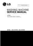
e_ka250.book Page 1 Tuesday, September 5, 2006 11:13 AM KA-HD250 STUDIO ADAPTER STUDIO ADAPTER KA-HD250 For Customer Use: Enter below the Serial No. which is located on the body. Retain this information for future reference. Model No. KA-HD250 Serial No. © 2006 Victor Company of Japan, Limited LST0445-001A INSTRUCTIONS LST0445-001A e_ka250.book Page 2 Tuesday, September 5, 2006 4:10 PM INTRODUCTION These are general important Safeguards and certain items may not apply to all appliances. Important Safeguards 1. 2. 3. 4. 5. 6. 7. 8. 9. 10. 2 Read all of these instructions. Save these instructions for later use. All warnings on the product and in the operating instructions should be adhered to. Unplug this appliance system from the wall outlet before cleaning. Do not use liquid cleaners or aerosol cleaners. Use a damp cloth for cleaning. Do not use attachments not recommended by the appliance manufacturer as they may cause hazards. Do not use this appliance near water – for example, near a bathtub, washbowl, kitchen sink, or laundry tub, in a wet basement, or near a swimming pool, etc. Do not place this appliance on an unstable cart, stand, or table. The appliance may fall, causing serious injury to a child or adult, and serious damage to the appliance. Use only with a cart or stand recommended by the manufacturer, or sold with the appliance. Wall or shelf mounting should follow the manufacturer’s instructions, and should use a mounting kit approved by the manufacturer. An appliance and cart combination should be moved with care. Quick stops, excessive force, and uneven surfaces may cause the appliance and cart combination to overturn. Slots and openings in the cabinet and the back or bottom are provided for ventilation, and to insure reliable operation of the appliance and to protect it from overheating, these openings must not be blocked or covered. The openings should never be blocked by placing the appliance on a bed, sofa, rug, or other similar surface. This appliance should never be placed near or over a radiator or heat register. This appliance should not be placed in a built-in installation such as a bookcase unless proper ventilation is provided. This appliance should be operated only from the type of power source indicated on the marking label. If you are not sure of the type of power supplied to your home, consult your dealer or local power company. For appliance designed to operate from battery power, refer to the operating instructions. This appliance system is equipped with a 3-prong grounding type plug (a plug having a third (grounding) pin). This plug will only fit into a grounding-type power outlet. This is a safety feature. If your power outlet is not this type, contact your electrician to have it replaced in order to utilize the grounding plug. Do not defeat the safety purpose of the grounding plug. 11. 12. 13. 14. 15. 16. 17. For added protection for this product during a lightning storm, or when it is left unattended and unused for long periods of time, unplug it from the wall outlet and disconnect the antenna or cable system. This will prevent damage to the product due to lightning and power-line surges. Do not allow anything to rest on the power cord. Do not place this appliance where the cord will be abused by persons walking on it. Follow all warnings and instructions marked on the appliance. Do not overload wall outlets and extension cords as this can result in fire or electric shock. Never push objects of any kind into this appliance through cabinet slots as they may touch dangerous voltage points or short parts that could result in a fire or electric shock. Never spill liquid of any kind on the appliance. Do not attempt to service this appliance yourself as opening or removing covers may expose you to dangerous voltage or other hazards. Refer all servicing to qualified service personnel. Unplug this appliance from the wall outlet and refer servicing to qualified service personnel under the following conditions: a. b. c. d. The power cord or plug is damaged or frayed. Liquid has been spilled into the appliance. The appliance has been exposed to rain or water. The appliance does not operate normally by following the operating instructions. Adjust only those controls that are covered by the operating instructions as improper adjustment of other controls may result in damage and will often require extensive work by a qualified technician to restore the appliance to normal operation. e. The appliance has been dropped or the cabinet has been damaged. f. The appliance exhibits a distinct change in performance – this indicates a need for service. 18. 19. When replacement parts are required, be sure the service technician has used replacement parts specified by the manufacturer that have the same characteristics as the original part. Unauthorized substitutions may result in fire, electric shock, or other hazards. Upon completion of any service or repairs to this appliance, ask the service technician to perform routine safety checks to determine that the appliance is in safe operating condition. e_ka250.book Page 3 Tuesday, September 5, 2006 4:10 PM Safety Precautions (For USA and Canada) CAUTION RISK OF ELECTRIC SHOCK DO NOT OPEN CAUTION: TO REDUCE THE RISK OF ELECTRIC SHOCK, DO NOT REMOVE COVER (OR BACK). NO USER SERVICEABLE PARTS INSIDE. REFER SERVICING TO QUALIFIED SERVICE PERSONNEL. THIS DEVICE COMPLIES WITH PART 15 OF THE FCC RULES. OPERATION IS SUBJECT TO THE FOLLOWING TWO CONDITIONS: (1) THIS DEVICE MAY NOT CAUSE HARMFUL INTERFERENCE, AND (2) THIS DEVICE MUST ACCEPT ANY INTERFERENCE RECEIVED, INCLUDING INTERFERENCE THAT MAY CAUSE UNDESIRED OPERATION. This unit should be used with 12 V DC only. CAUTION: To prevent electric shocks and fire hazards, DO NOT use any other power source. The lightning flash with arrowhead symbol, within an equilateral triangle is intended to alert the user to the presence of uninsulated “dangerous voltage” within the product’s enclosure that may be of sufficient magnitude to constitute a risk of electric shock to persons. The exclamation point within an equilateral triangle is intended to alert the user to the presence of important operating and maintenance (servicing) instructions in the literature accompanying the appliance. INFORMATION: This equipment has been tested and found to comply with the limits for a Class B digital device, pursuant to Part 15 of the FCC Rules. These limits are designed to provide reasonable protection against harmful interference in a residential installation. This equipment generates, uses, and can radiate radio frequency energy and, if not installed and used in accordance with the instructions, may cause harmful interference to radio communications. However, there is no guarantee that interference will not occur in a particular installation. If this equipment does cause harmful interference to radio or television reception, which can be determined by turning the equipment off and on, the user is encouraged to try to correct the interference by one or more of the following measures: z Reorient or relocate the receiving antenna. z Increase the separation between the equipment and receiver. z Connect the equipment into an outlet on a circuit different from that to which the receiver is connected. z Consult the dealer or an experienced radio/TV technician for help. CAUTION: CHANGES OR MODIFICATIONS NOT APPROVED BY JVC COULD VOID USER’S AUTHORITY TO OPERATE THE EQUIPMENT. NOTE: The rating plate (serial number plate) is on this unit. WARNING: TO REDUCE THE RISK OF FIRE OR ELECTRIC SHOCK, DO NOT EXPOSE THIS APPLIANCE TO RAIN OR MOISTURE. 3 e_ka250.book Page 4 Tuesday, September 5, 2006 4:10 PM INTRODUCTION Safety Precautions (For Europe) WARNING: TO REDUCE THE RISK OF FIRE OR ELECTRIC SHOCK, DO NOT EXPOSE THIS APPLIANCE TO RAIN OR MOISTURE. This unit should be used with 12 V DC only. CAUTION: To prevent electric shocks and fire hazards, do NOT use any other power source. CAUTION: To prevent electric shock, do not open the cabinet. No user serviceable parts inside. Refer servicing to qualified service personnel. Note: The rating plate (serial number plate) is on this unit. This equipment is in conformity with the provisions and protection requirements of the corresponding European Directives. This equipment is designed for professional video appliances and can be used in the following environments: z Residential (including both of the location type class 1 and 2 found in IEC 1000-2-5) z Commercial and light industrial (including, for example, theatres) z Urban outdoors (based on the definition of location type class 6 in IEC 1000-2-5) In order to keep the best performance and furthermore for electromagnetic compatibility we recommend to use cables not exceeding the following lengths: Port Cable Length RM Exclusive Cable 100 meters PROMPTER OUTPUT Coaxial Cable 5 meters DC INPUT Exclusive Cable 5 meters Caution: Where there are strong electromagnetic waves or magnetism, for example near a radio or TV transmitter, transformer, motor, etc., the picture and sound may be disturbed. In such a case, please keep the apparatus away from the sources of the disturbance. 4 e_ka250.book Page 5 Tuesday, September 5, 2006 4:10 PM Thank you for purchasing this product. (These instructions are for: KA-HD250U.) Before operating this unit, read the instruction manual carefully in order to make sure that the best possible performance is obtained. Main Features Equipped with Analog 26P Camera Connector Connect the Remote Control Unit RM-P210 (sold separately) to control this unit from up to a distance of 100 m away. In this case, the remote control unit provides power for the camera and thus there is no requirement for a separate power supply for the camera. Multi-system Output Output composite signals and RGB component, Y/PB/PR component, or YC separate signals from the 26P camera connector. (Selectable with the menu switch.) Equipped with Intercom Terminal Use a headset to communicate with the remote control unit operator. (Dynamic only) Contents INTRODUCTION Main Features . . . . . . . . . . . . . . . . . . . . . . . . . . . . . . . . . . .5 Operating Precautions . . . . . . . . . . . . . . . . . . . . . . . . . . . . .6 Regarding Genlock Signal and Adjustment of System Phase . . . . . . . . . . . . . . . . . . . . . . . . . . . . . . . . . . . .6 Controls, Indicators and Connectors . . . . . . . . . . . . . . . . . .7 Front Section. . . . . . . . . . . . . . . . . . . . . . . . . . . . . . . . . .7 Rear Section . . . . . . . . . . . . . . . . . . . . . . . . . . . . . . . . . .8 Bottom Section . . . . . . . . . . . . . . . . . . . . . . . . . . . . . . . .8 PREPARATIONS Basic System . . . . . . . . . . . . . . . . . . . . . . . . . . . . . . . . . . . .9 Installation . . . . . . . . . . . . . . . . . . . . . . . . . . . . . . . . . . . . .10 Mounting on a Tripod . . . . . . . . . . . . . . . . . . . . . . . . . .10 Mounting the Camera . . . . . . . . . . . . . . . . . . . . . . . . . .10 Connecting Cables . . . . . . . . . . . . . . . . . . . . . . . . . . . .11 Connecting the Viewfinder (VF-P400) . . . . . . . . . . . . .11 Connecting to Remote Control Unit RM-P210 . . . . . . . . . .12 Connection . . . . . . . . . . . . . . . . . . . . . . . . . . . . . . . . . .12 Menu Screen Setting . . . . . . . . . . . . . . . . . . . . . . . . . .12 Switch Setting . . . . . . . . . . . . . . . . . . . . . . . . . . . . . . . .12 Operation . . . . . . . . . . . . . . . . . . . . . . . . . . . . . . . . . . .13 Notes on Operating RM-P210 . . . . . . . . . . . . . . . . . . . . . .14 OTHERS Specifications . . . . . . . . . . . . . . . . . . . . . . . . . . . . . . . . . . .15 Dimensions . . . . . . . . . . . . . . . . . . . . . . . . . . . . . . . . . .15 Equipped with Prompter Output Terminal Output prompter video from the remote control unit as composite signals. VF-P400 4-inch Viewfinder Compatible A general-purpose viewfinder can also be connected. Features External Monitor Component Terminals (BNC × 3) 5 e_ka250.book Page 6 Tuesday, September 5, 2006 4:10 PM INTRODUCTION Operating Precautions • In order to ensure that this unit serves you longer, avoid storing or using in the following. Extremely hot or cold places Strong vibrations Dusty places High humidity Near loud noise sources • Do not subject this unit to strong vibration or impact when installing or moving it. • Do not plug in or unplug the camera cable connector when this unit is powered on. • Use only the designated power supplies. Use either RMP210 or IDX IA-60a, VL-2PLUS. • To reduce power consumption, turn off the power when not in-use. • When a transceiver or mobile phone is used near this unit, noise may occur in the intercom speaker or the screen. This is not a malfunction. • Grounding the INTERCOM G (GND) terminal is recommended as noise may be induced depending on the intercom headset used. • Use only the specified standard length camera cable. Otherwise, cable compensation may be insufficient. Regarding Genlock Signal and Adjustment of System Phase When using the RM-P210 Remote Control Unit with this system, input Genlock signal into either the GY-HD250 Camera or RM-P210. However, if Genlock signal is applied to both GY-HD250 and RM-P210, screen images will appear choppy. Perform System Phase adjustment on the machine where Genlock signal has been input. In addition, RM-LP55 is prioritized when connected. • When Genlock signal is input into RM-P210 Adjust the phase by adjusting RM-P210’s H and SC. Use RM-LP55 to adjust the phase if it is connected to this system. • When Genlock signal is input into GY-HD250 • Adjust the phase by adjusting GY-HD250 H and SC. (Adjustment should be performed through GY-HD250 even if RM-P210 is connected.) Use RM-LP55 to adjust the phase if it is connected to this system. CAUTION • Moving this unit with the supporting tripod attached may cause it to detach and fall if there is a sudden external impact or vibration. This may cause injuries. Remove this unit from the tripod before moving it. • The front base mount may lock even when the pin on this device and the rear base mount attachment hole on the camera is not attached. After attaching, confirm that the camera has been firmly attached. The camera may fall and cause injury or accident if it is not attached properly. • When transporting with the camera attached to this device, hold the bottom of this device. If transported with the camera handle, the attachment may come off and this device may fall and cause injury or accident. How to Use This Manual Characters and symbols used in this manual CAUTION : Points to pay attention to during operation. NOTE : Details for reference, such as functions or constraints during use. X : Pages or items to refer to. Notation used in this manual • The copyright for this manual is property of JVC. Unauthorized reproduction or publication of this manual in part or in whole is strictly forbidden. • All product names that appear in this document are the trademarks or registered trademarks of their respective companies. Marks and symbols such as ™, ® and © do not appear in this document. • The design, specifications, etc. found in this manual are subject to change without notice for improvement. • This manual refers to the connecting camera as GYHD250. However, the same operations are used when connecting the GY-HD251. 6 e_ka250.book Page 7 Tuesday, September 5, 2006 4:10 PM MEMO Controls, Indicators and Connectors • When the viewfinder is connected to this terminal, the signal is not output correctly even if the viewfinder is connected to the 3 [VF OUTPUT] terminal. • When connected to the Y/PB/PR terminal of the monitor, the return video signal from the RM-P210 appears in black and white. Front Section 8[TALLY OUTPUT] Tally Signal Output Terminal (D-sub 9 pin) Output tally signals. Use when connecting a VF other than VF-P400. 1 6 2 Signal 1 NC 6 NC 2 RM_PREVIEW 7 RM_TALLY 3 NC 8 NC 5 4 NC 9 NC (Surface profile) 5 GND 1 3 Signal 9 9[TALLY INPUT] Input tally signals. f e d 4 c 9 0 b 9 a 8 7 6 5 2Lock Lever Fastens the camera to this unit. X See “Mounting the Camera” on page 10. 3[VF OUTPUT] round 20-pin Connect the VF-P400 4-inch Viewfinder (sold separately). X See “Connecting the Viewfinder (VF-P400)” on page 11. 4[PROMPTER OUTPUT] Prompter Output Terminal (BNC) The prompter video signal input to the [AUX] input terminal of the remote control unit is output from this terminal via the RM multi-pin connector. Composite signal is output. Video monitor is connected here. 5[VF] Viewfinder Cable Connect to the VF terminal of GY-HD250. 6[BREAKER] Breaker Switch Breaker switch trips and cuts off power if the power consumed is higher than the rated capacity. If the breaker switch trips, confirm that there are no abnormalities and that the power consumption does not exceed the rated wattage. If no abnormalities are detected, press the breaker switch before turning the power on again to put this unit in the operating status. If this unit still does not function properly, consult your JVC-authorized dealer. 7[VF OUTPUT] (Y/PB/PR/RGB) BNC×3 Component output terminal for viewfinder.Use when connecting a Viewfinder other than VF-P400. The HD/SD (from the GY-HD250) and composite video signal (from the RM-P210) can be switched. Use the GYHD250 menu to set. Recommended viewfinder: • DM-3106 (Astrodesign) • V-R70P-HAD (Marshall Electronics) Signal 1 NC 6 NC 2 TALLY_IN 7 NC 3 NC 8 NC 1 4 NC 9 NC (Surface profile) 5 GND 5 1Viewfinder Holder Use for mounting the VF-P400 4-inch Viewfinder. Signal 6 0[RM] RM Multi-pin Connector (26 Pin) Connect to Remote Control Unit RM-P210 by using the 26-pin camera cable. In addition, power is supplied to this unit and the camera from the remote control unit via this connector. MEMO • Output Composite video signal and RGB component, Y/ PB/PR component and YC separate signals from the output terminal of RM-P210. Select the output signal using the “OUTPUT” item on the “SYSTEM” menu screen on the GY-HD250. • SD1 and HD signal cannot be output to the RM-P210. aGenlock Output Cable (BNC) Output cable for synchronization signals. Connect to the GENLOCK output terminal of GY-HD250. bComposite Video Input Cable (RCA) Input cable for composite video signals. Connect to the VIDEO output terminal of GY-HD250. cDC Output Cable (XLR 4pin) Connect to the DC INPUT terminal of GY-HD250. dComponent Y/PB/PR Input Cable (BNC×3) Input cable for component video Y/PB/PR signals. Connect to the each of the Y/PB/PR output terminals of GY-HD250. e[CONTROL] Control Cable (Round 9 pin) Connect to the STUDIO terminal of GY-HD250. f[REMOTE] Remote Cable (Round 6 pin) Connect to the REMOTE terminal of GY-HD250. 7 e_ka250.book Page 8 Tuesday, September 5, 2006 4:10 PM INTRODUCTION Controls, Indicators and Connectors (Cont’d) Rear Section g k[CALL] CALL button/Power indicator Lights green when the studio adapter is turned on. Press to send call signal to the remote control unit operator if intercom headset is not in-use. Button indicator changes from green to red when the button is pressed. When this button is pressed and held down, call signal is sent to the remote control unit and the [TALLY] indicator blinks. Once the [CALL] button is released, call signal is no longer sent and the [TALLY] indicator of the remote control unit turns off. l[DC INPUT] DC Power Input Terminal (XLR 4 Pin) Connect DC power to this terminal if Remote Control Unit RM-P210 is not connected. For DC power supply, use the IDX IA-60a or VL-2PLUS. CAUTION When cable is connected to the DC INPUT terminal while supplying power from the RM-P210, power will flicker. Turn off connected devices when connecting a cable to the DC INPUT terminal. Bottom Section INTERCOM DC INPUT PUSH INTERCOM MIC INTERCOM LEVEL CALL ON OFF h MIN i MAX j k l g[TALLY] TALLY Lamp Lights up red when GY-HD250 is in RECORDING mode. Blinks red when preparing RECORDING mode and lights up green when in stand-by. h[INTERCOM] Intercom Input Terminal (XLR 5 Pin) Input terminal for intercom headset. (Dynamic only) Recommended headset: DT109 (Beyerdynamic) 1 Signal 5 2 4 3 (Surface profile) 1 MIC (H) 2 MIC (C) 3 EAR (C) 4 EAR (H) – LEFT 5 EAR (H) – RIGHT i[INTERCOM MIC] Intercom Mic [ON/OFF] Switch [ON/OFF] switch for intercom headset microphone. Set to [ON] to use the headset microphone. j[INTERCOM LEVEL] Intercom Receiver Volume Use for adjusting the intercom headset receiver volume level. 8 m mScrew Holes for Mounting Tripod e_ka250.book Page 9 Tuesday, September 5, 2006 4:10 PM PREPARATIONS Basic System View Finder DM-3106 (Astrodesign) V-R70P-HAD (Marshall Electronics) View Finder VF-P400 Conversion plug VF BRIGHT MACRO USER 1 USER 2 USER 3 ND FILTER 2 1 MENU STATUS WHT.BAL AUTO CH-1 ON AUTO AUDIO LEVEL CH-2 VF OUTPUT terminal (BNC × 3) VF OUTPUT terminal (Round 20-Pin) Headset DT109 (Beyerdynamic) OFF POWER REC HD CAMERA RECORDER GY-HD250/GY-HD251 INTERCOM terminal STUDIO KIT KA-HD250 DC cable AC Power Adapter IA-60a, VL-2PLUS (IDX) DC INPUT terminal PROMPTER OUTPUT terminal RM terminal REMOTE cable Tripod TP-P300 REMOTE CONTROL UNIT RM-P210 TALLY CALL FULL AUTO F1 BARS F2 SHUTTER F3 MENU/SHUTTER GAIN PAINT WHITE PUSH-ON VARIABLE PUSH-ON POWER B MID LOW IRIS W.BAL HIGH MENU MASTER BLACK AUTO STEP SHUTTER F4 I A R B PRESET AUTO MANU GAIN INTERCOM LEVEL Monitor O DOWN UP DOWN UP CLOSE OPEN Remote Control Unit RM-P210 Headset DT109 (Beyerdynamic) Dolly TP-P205 z Power is supplied by the Remote Control Unit RM-P210 via the 26 pin camera cable when in-use. If the Remote Control Unit RM-P210 is not in-use, use AC power adapter. 9 e_ka250.book Page 10 Tuesday, September 5, 2006 4:10 PM PREPARATIONS 2. Release the LOCK RELEASE LEVER. Installation Push the safety lever until the front attachment clip clicks, and then pull the lock lever. Mounting on a Tripod Lock lever Use the screw holes on the bottom to mount on a tripod. There are multiple screw holes. Use well-balanced holes to mount to a tripod. Safety lever 3. Position the camera. Screw holes Position the camera so the rear base mount is aligned with the pin on this device. Mounting the Camera Prepare the camera as follows before mounting. • Attach the lens. • Attach the microphone. • Remove the viewfinder. For details, refer to GY-HD250’s INSTRUCTION MANUAL. 1. Open the side cover. Rear base mount Front base mount 4. Lock the camera. Hold the camera on the top and slide forward. The front base mount of the camera and the front attachment grip of this device locks and clicks. CAUTION • The front base mount may lock even when the pin on this device and the rear base mount attachment hole on the camera is not attached. After attaching, confirm that the camera has been firmly attached. The camera may fall and cause injury or accident if it is not attached properly. • When transporting with the camera attached to this device, hold the bottom of this device. If transported with the camera handle, the attachment may come off and this device may fall and cause injury or accident. 10 e_ka250.book Page 11 Tuesday, September 5, 2006 4:10 PM Connecting Cables Connecting the Viewfinder (VF-P400) Connect the cables for this device to the camera. 2. 3. 1. 9 4 GENLOCK/AUX IN P TC IN P TC OUT IEEE 1394 REMOTE CH2-AUDIO OUT-CH1 VIDEO HD/SD SDI 1. Loosen the lock lever. Y 1 2 5 Turn the viewfinder lock lever counterclockwise and loosen the lock lever. 6 7 2. Attach the viewfinder. Slide the viewfinder forward along the viewfinder holder guides on the top of this device. DC INPUT 3 STUDIO 3. Tighten with the lock lever. 8 Connect the cable for this device to the camera terminal. Cable GENLOCK (type) Camera terminal (BNC) 1 GENLOCK IN REMOTE (Round 6-pin) 2 REMOTE DC OUTPUT (XLR 4-pin) 3 DC INPUT VIDEO (RCA) 4 VIDEO OUTPUT Y (BNC) 5 Y IN PB (BNC) 6 PB IN PR (BNC) 7 PR IN STUDIO (Round 10-pin) 8 STUDIO VF (Round 20-pin) 9 VF Turn the viewfinder lock lever clockwise and tighten the lock lever. 4. Connect the cables. Connect the viewfinder cable and conversion plug and connect the conversion plug to the viewfinder output terminal (20 pin) of this device. 4. MEMO • Turn off the device before connecting cables. • Do not touch the plug terminals when connecting. • Insert the DC cable plug all the way in until it locks. MEMO • Signals are not output from the VF OUTPUT (Y/PB/PR/ RGB) BNC terminal on the side of this device. • Do not connect anything other than the specified viewfinder to the viewfinder output terminal (20 pins). 11 e_ka250.book Page 12 Tuesday, September 5, 2006 4:10 PM PREPARATIONS Connecting to Remote Control Unit RM-P210 3. Connecting a Monitor Prompter video (RM-P210 [AUX VIDEO INPUT] terminal input signal) from RM-P210 can be verified by connecting this unit’s [PROMPTER OUTPUT] terminal located in the front to a monitor using a BNC cable. MEMO Connection Switch off RM-P210 power supply before attempting the connection. 4. • Power for this unit and the camera are supplied by RMP210 via the 26 pin camera cable. • 26 pin camera cable VC-P110 (5 m) VC-P112 (20 m) VC-P113 (50 m) VC-P114 (100 m) Menu Screen Setting 1. Output Signal Setting Composite video signal is always output from the RM multi-pin connector. In addition, RGB component, Y/PB/ PR component or YC separate signal can also be output. Select the output signal using the OUTPUT item on the SYSTEM menu screen MEMO Sync signals are superimposed onto RGB component signals. Switch Setting 1. Enabling/disabling INCOM MIC Set the [INCOM MIC ON/OFF] switch depending on whether headset microphone will be used. Set the switch to [ON] use the headset microphone. 1. Connecting the RM-G210 Connect this unit’s RM multi-pin connector and RM-P210 using the 26 pin camera cable. Length of the camera cable should not be longer than 100 m. 2. Connecting the DT-109U Connect the Headset DT-109U plug to the [INTERCOM] terminal to use an intercom headset. MEMO This device supports only DYNAMIC-type headset. CARBON-type headphones cannot be connected. 12 INCOM MIC ON/OFF switch e_ka250.book Page 13 Tuesday, September 5, 2006 4:10 PM MEMO Operation 1. Turn the RM-P210 on. Turn the [POWER] switch of the camera remote control unit to [ON]. CALL button lights up green when the power is turned on. After the [POWER] switch is turned on, camera remote control unit can be operated after about 30 seconds. MEMO After the power is turned on, the camera remote control unit takes about 30 seconds to be ready to communicate with this unit. • If both this unit (including the camera) and the remote control unit have the same functional switches, the remote control unit switches are prioritized. • If local Remote Control Unit (RM-LP55 or RM-LP57) is used simultaneously, the local remote control unit is prioritized. • If external synchronization signal is present when the power is turned on, pictures may appear choppy for a few seconds. This is not a malfunction. • When using the remote control unit, refer to its instruction manual for details. 2. Press the [CALL] button. Press and hold down the [CALL] to send call signals to the remote control unit operator. The [TALLY] button indicator of the remote control unit blinks. [CALL] button indicator changes from green to red while the button is pressed. The [TALLY] lamp on the viewfinder also blinks when call signals are received from the remote control unit. 3. Adjust the volume. Adjust the headset reception volume with [INCOM LEVEL]. INCOM LEVEL volume CALL button 13 e_ka250.book Page 14 Tuesday, September 5, 2006 4:10 PM PREPARATIONS Function Notes on Operating RMP210 GAMMA Some actions are not compatible when setting the GYHD250 with RM-P210 menu operations. OFF Function Action OFF G ON G DETAIL OFF G (CONTOUR) ON G IRIS WHITE BAL AUTO GAIN TALLY MANU G AUTO G MANU G PRE G AUTO1 G AUTO2 G FAW G SET × WHITE G 0dB G +3dB G +6dB G +9dB G +12dB G +15dB G +18dB G +24dB × –3dB × ALC-EEl G VARIABLE GAIN2 × VARIABLE GAIN × OFF G ON G PREVIEW G G VOLTAGE CHK. (RM r CAM) G VOLTAGE CHK. (CAM r RM) HIGH G LOW G SHUTTER OFF G 1/100 G*1 1/120 G*2 1/250 G 1/500 G 1/1000 G 1/2000 G SHUTTER V.SCAN × NORMAL G STRETCH G COMPRESS G NORMAL (OFF) × (HI-RESO) V.MAX (ON) × AUTO KNEE OFF G ON G BLACK 14 × ON × DNR OFF G ON G DNR LEVEL LOW × MIDDLE × (G: Action available ×: No action) BAR Action DTL FRQ SKIN DTL COLOR MATRIX ASPECT RATIO HIGH × AUTO × LOW G MIDDLE G HIGH G AUTO × OFF G ON G OFF × ON × 4:3 × 16:9 × LETTER × FULL AUTO SHOOTING OFF G ON G LOLUX OFF × ON × SMOOTH TRANS OFF G ON G × *1 When frame rate is 60p, 60i, 30p, or 24p *2 When frame rate is 50p, 50i, or 25p Level command Function G IRIS MAUAL WHITE BALANCE BLACK PAINT Action R G B G R × B × MASTER BLACK G H.PHASE G DETAIL MASTER G DETAIL BAL H/V G WHITE PAINT R G B G KNEE MASTER G GAMMA MASTER × IRIS LEVEL (AL) G VARIABLE SHUTTERT × VARIABLE GAIN2 × e_ka250.book Page 15 Tuesday, September 5, 2006 4:10 PM OTHERS Specifications RM Multi-pin connector: Composite video signal output (Either Y/PB/PR, RGB or YC separate output signal can be selected) PROMPTER output: PROMPTER video signal output (composite signal) Operating temperature range: • –5°C to 40°C (Humidity below 80%) Allowable storage temperature: • –20°C to 60°C Power supply voltage: DC12 V Power consumption: Max. 40W (GY-HD250, VF-P400) Mass: Approx. 1.8 f Accessories: Instructions ........................................................................× 1 Dimensions (Unit: mm) INTERCOM DC INPUT VF OUTPUT PUSH INTERCOM MIC INTERCOM LEVEL CALL G/Y ON TALLY INPUT OFF MIN B/PB R/PR TALLY OUTPUT 60 253 243 80 MAX 176 204 325 333 67 96(=6xP16) 22 48(=3xP16) Specifications and appearance of this unit are subject to change for further improvement without prior notice. 15