1
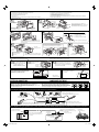
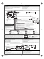
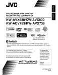
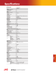
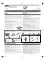
KW-AVX838/KW-AVX830/KW-ADV793/KW-AVX738/KW-AVX730
Installation/Connection Manual
Manual de instalación/conexión
LVT2087-001B
[J/JW]
0110NYMMDWJEIN
EN, SP
© 2010 Victor Company of Japan, Limited
ENGLISH
ESPAÑOL
This unit is designed to operate on 12 V DC, NEGATIVE ground electrical systems. If your vehicle does
not have this system, a voltage inverter is required, which can be purchased at JVC car audio dealers.
Esta unidad está diseñada para funcionar con 12 V de CC, con sistemas eléctricos de masa
NEGATIVA. Si su vehículo no posee este sistema, será necesario un inversor de tensión, que puede ser
adquirido en los concesionarios de JVC de equipos de audio para automóviles.
WARNINGS
ADVERTENCIAS
• DO NOT install any unit or wire any cable in a location where;
– it may obstruct the steering wheel and gearshift lever operations, as this may result in a traffic accident.
– it may obstruct the operation of safety devices such as air bags, as this may result in a fatal accident.
– it may obstruct visibility.
• DO NOT operate any unit while manipulating the steering wheel, as this may result in a traffic accident.
• The driver must not watch the monitor while driving. It may lead to carelessness and cause an accident.
• If you need to operate the unit while driving, be sure to look around carefully or you may be involved in
a traffic accident.
• If the parking brake is not engaged, “Parking Brake” appears on the monitor, and no playback picture
will be shown.
– This warning appears only when the parking brake lead is connected to the parking brake system built
in the car.
• NO instale ningún receptor o tienda ningún cable en una ubicación donde;
– donde pueda obstruir la maniobra del volante de dirección y del cambio de engranajes, con el
consiguiente riesgo de accidentes de tráfico.
– donde pueda obstruir el funcionamiento de dispositivos de seguridad tales como bolsas de aire,
pues podría resultar en un accidente fatal.
– donde pueda obstruir la visibilidad.
• NO OPERE la unidad mientras está maniobrando el volante de dirección, pues podría producirse un
accidente de tráfico.
• El conductor no debe mirar el monitor mientras conduce. Podría producirse un descuido, y causar un accidente.
• Si necesita operar la unidad mientras conduce, asegúrese de mirar atentamente a su alrededor pues
de lo contrario, se podría producir un accidente de tráfico.
• Si el freno de mano no está en uso, aparecerá “Parking Brake (Freno de Mano)” en la pantalla y no se
mostrará ninguna secuencia de imagen.
– Esta advertencia aparece únicamente cuando el cable del freno de estacionamiento se encuentra
conectado al sistema del freno de estacionamiento incorporado al automóvil.
To prevent short circuits, we recommend that you disconnect the battery’s negative terminal and make all
electrical connections before installing the unit.
• Be sure to ground this unit to the car’s chassis again after installation.
• Be sure any cable is not caught on the car’s chassis or under seats.
Para evitar cortocircuitos, recomendamos que desconecte el terminal negativo de la batería y que
efectúe todas las conexiones eléctricas antes de instalar la unidad.
• Asegúrese de volver a conectar a masa esta unidad al chasis del automóvil después de la
instalación.
• Asegúrese de que ningún cable quede atrapado en el chasis del automóvil o debajo de los asientos.
Notes on electrical connections:
• Replace the fuse with one of the specified rating. If the fuse blows frequently, consult your JVC car audio
dealer.
• It is recommended to connect speakers with maximum power of more than 50 W (both at the rear and
at the front, with an impedance of 4 Ω to 8 Ω).
If the maximum power is less than 50 W, change <Amplifier Gain> setting to prevent the speakers from
being damaged (see page 35 of the INSTRUCTIONS).
• To prevent short circuits, cover the terminals of the UNUSED leads with insulating tape.
• The heat sink becomes very hot after use. Be careful
not to touch it when removing this unit.
• At the time of installation, be sure to fix all wires
Heat sink
(wires both from this unit and from the car itself) in
Sumidero térmico
a way that any wires cannot come into contact with
heat sinks on the rear and side of the unit.
Notas sobre las conexiones eléctricas:
• Reemplace el fusible por otro del régimen especificado. Si el fusible se funde frecuentemente,
consulte con su concesionario de JVC de equipos de audio para automóviles.
• Se recomienda conectar los altavoces con una potencia máxima de más de 50 W (tanto atrás como
adelante, con una impedancia de 4 Ω a 8 Ω).
Si la potencia máxima es de menos de 50 W, cambie <Amplifier Gain> para evitar daños en los
altavoces (consulte la página 35 del MANUAL DE INSTRUCCIONES).
• Para evitar cortocircuitos, cubra los cables NO UTILIZADOS con cinta aislante.
• El sumidero térmico estará muy caliente después del uso. Asegúrese de no tocarlo al desmontar esta unidad.
• Al realizar la instalación, asegúrese de fijar todos los cables (tanto los que proceden de esta unidad
como los del vehículo en sí) de manera tal que ninguno quede en contacto con los disipadores
térmicos de las partes traseras y laterales de la unidad.
Parts list for installation and connection
Lista de piezas para instalación y conexión
The following parts are provided for this unit.
If anything is missing, contact your dealer immediately.
Con esta unidad se suministran las siguientes piezas.
Si hay algún elemento faltante, póngase inmediatamente en contacto con su concesionario.
Main unit/Sleeve/Trim plate
Unidad principal/Cubierta/Placa
de guarnición
Monitor panel and soft case
Panel del monitor y estuche blando
Handles
Manijas
Crimp connector
Conector de sujeción
Flat head screws (M5 x 8 mm/M5 x 3/8”)
Tornillos de cabeza plana
(M5 x 8 mm/M5 x 3/8 pulgada)
Round head screws (M5 x 8 mm/M5 x 3/8”)
Tornillos de cabeza esférica
(M5 x 8 mm/M5 x 3/8 pulgada)
Power cord
Cordón de alimentación
Mounting bolt—M4 × 20 mm/M4 x 13/16”
Perno de montaje—
M4 x 20 mm/M4 x 13/16 pulgada
Washer (ø5)
Arandela (ø5)
Rubber cushion
Cojín de goma
Lock nut (M5)
Tuerca de
seguridad (M5)
Only for KW-AVX838/KW-AVX738
Sólo para KW-AVX838/KW-AVX738
Only for KW-AVX838/KW-AVX830
Sólo para KW-AVX838/KW-AVX830
Remote controller
Control remoto
Bluetooth adapter (See page 4.)
Adaptador Bluetooth (Consulte la
página 4.)
Microphone clip
Presilla para micrófono
KS-UBT1
Use these screws when installing
the unit without the supplied sleeve.
(See below.)
Utilice estos tornillos cuando
instale la unidad sin la cubierta
suministrada. (véase abajo)
Microphone
Micrófono
Microphone holder
Soporte del micrófono
INSTALLATION (IN-DASH MOUNTING)
INSTALACIÓN (MONTAJE EN EL TABLERO DE INSTRUMENTOS)
The following illustration shows a typical installation. However, you should make adjustments
corresponding to your specific car. If you have any questions or require information regarding installation
kits, consult your JVC car audio dealer or a company supplying kits.
• If you are not sure how to install this unit correctly, have it installed by a qualified technician.
La siguiente ilustración muestra una instalación típica. Sin embargo usted deberá efectuar los
ajustes correspondientes a su automóvil. Si tiene alguna pregunta o necesita información acerca de
las herramientas para instalación, consulte con su concesionario de JVC de equipos de audio para
automóviles o a una compañía que suministra tales herramientas.
• Si no está seguro de poder instalar la unidad correctamente, déjela en manos de un técnico cualificado.
Before installing the unit
Antes de instalar la unidad
• Remove the audio system originally installed in the car, together with its mounting brackets. Be sure to
keep all the screws and parts removed from your car for future use.
• When mounting the unit, be sure to use the screws provided, as instructed. If other screws are used,
parts could become loose or damaged.
• When tightening screws or bolts, be careful not to pinch any connection cord.
• Make sure not to block the fan on the rear to maintain proper ventilation when installing the unit.
• You cannot install the unit on the car which has any obstacles in the space shown in “Required space for
installation and the monitor panel ejection” on the following page.
• Desmonte el sistema de audio instalado originalmente en el coche, junto con los ménsulas de montaje.
Asegúrese de guardar todos los tornillos y piezas quitados de su vehículo para poderlos usar en el futuro.
• Al instalar la unidad, asegúrese de usar los tornillos suministrados, de acuerdo con las instrucciones.
El uso de otros tornillos podrá provocar flojedad de o daños a las piezas.
• Al apretar los tornillos o los pernos, asegúrese de que ningún cable de conexión quede pillado.
• Al efectuar la instalación, asegúrese de no bloquear el ventilador del panel trasero a fin de mantener
una ventilación correcta.
• No podrá instalar la unidad en un coche en que haya algún obstáculo en el espacio indicado en
“Espacio requerido para la instalación y la expulsión del panel del monitor” en la página siguiente.
When installing the unit without using the sleeve
• Use flat head screws or round head screws, depending on installation location. When you use flat head
screws to install the unit, use the screws removed in step 1 on the following page. When you use screws
other than those supplied, use 8 mm (3/8”)-long screws. If longer screws are used, they could damage
the unit.
• Tighten the screws firmly to prevent the unit from falling off.
Instalación de la unidad sin utilizar la cubierta
• Utilice tornillos de cabeza plana o esférica, dependiendo del lugar de instalación. Si decide utilizar
tornillos de cabeza plana para instalar la unidad, utilice los tornillos extraídos en el paso 1 de la
siguiente página. Si decide utilizar tornillos distintos de los suministrados, escoja tornillos de 8 mm
(3/8”) de largo. El uso de tornillos más largos producir daños a la unidad.
• Apriete los tornillos firmemente para evitar que la unidad se caiga.
1
Insta_KWAVX838[JWJ].indb 1
10.5.7 10:29:38 AM
1
2
3
4
5
6
1
2
3
4
Detach the trim plate and remove the screws.
Detach the sleeve using the handles then slide off the sleeve.
Install the sleeve in the dashboard of the car.
Do the required electrical connections.
• See pages 2 – 4.
Attach the trim plate to the main unit, then install the main unit in to the sleeve.
Attach the monitor panel.
1
5
6
Desmonte la placa de guarnición y extraiga los tornillos.
Sujetando las asas, desmonte la cubierta deslizándola.
Instale la cubierta en el tablero del automóvil.
Realice todas las conexiones eléctricas necesarias.
• Consulte las páginas 2 – 4.
Fije la placa de guarnición a la unidad principal y, a continuación, instale ésta en la cubierta.
Fije el panel del monitor.
2
Sleeve
Cubierta
Handles
Manijas
Flat head screws (M5 x 8 mm/M5 x 3/8”)
Tornillos de cabeza plana
(M5 x 8 mm/M5 x 3/8 pulgada)
Sleeve
Cubierta
Trim plate
Placa de
guarnición
Sleeve
Cubierta
3
When you stand the unit, be careful not to
damage the fuse on the rear.
Al poner la unidad vertical, tenga cuidado de no
dañar el fusible provisto en la parte posterior.
4
For more stable attachment / Para una fijación más estable
A
D E
B
A Stay (option) / Soporte (opción)
B Screw (option) / Tornillo (opción)
C Lock nut / Tuerca de seguridad
D Washer / Arandela
E Mounting bolt / Perno de montaje
C
To the rear panel / Al panel trasero
Bend the appropriate tabs to hold the sleeve firmly in place.
Doble las lengüetas apropiadas para retener firmemente la
manga en su lugar.
5
6
DO NOT press the panel (shaded in the illustration).
NO presione el panel (sombreado en la ilustración).
OK
Trim plate
Placa de guarnición
Sleeve
Cubierta
Do not block the fan.
No tape las rejillas de
ventilación.
Monitor panel
Panel del monitor
Slide the unit in until you hear a clicking sound.
Deslice la unidad hasta escuchar un chasquido.
Removing the unit
Extracción de la unidad
Before removing the unit, release the rear section.
Antes de extraer la unidad, libere la sección trasera.
2
3
Detach the trim plate.
Desmonte la placa de
guarnición.
Trim plate
Placa de
guarnición
Required space for installation and the
monitor panel ejection
Espacio requerido para la instalación y la
expulsión del panel del monitor
Insert the two handles, then pull them as
illustrated so that the unit can be removed.
Inserte las dos manijas y, a continuación,
jálelas tal como se muestra en la ilustración
para desmontar la unidad.
160 (6-5/16)
Handles
Manijas
Install the unit at an angle of less
than 30˚.
Instale la unidad a un ángulo de
menos de 30˚.
Dashboard
Tablero de instrumentos
20 (13/16)
100 (3-15/16)
Detach the monitor panel (see
page 5 of the INSTRUCTIONS).
Desmonte el panel del monitor
(consulte la página 5 del
MANUAL DE INSTRUCCIONES).
4 (3/16)
1
30˚
Unit: mm (inch)
Unidad: mm (pulgada)
91.7 (3-5/8)
ELECTRICAL CONNECTIONS
CONEXIONES ELECTRICAS
PRECAUTIONS on power supply and speaker connections:
• DO NOT connect the speaker leads of the power cord to the car
battery; otherwise, the unit will be seriously damaged.
• BEFORE connecting the speaker leads of the power cord to the speakers, check
the speaker wiring in your car.
PRECAUCIONES sobre las conexiones de la fuente de alimentación y de los altavoces:
• NO conecte los conductores de altavoz del cable de alimentación a la
batería de automóvil, pues podrían producirse graves daños en la unidad.
• ANTES de conectar a los altavoces los conductores de altavoz del cable de
alimentación, verifique el conexionado de altavoz de su automóvil.
Connecting the parking brake lead / Conexión del cable del freno de estacionamiento
Parking brake lead (light green)
Cable del freno de estacionamiento (verde claro)
Parking brake
Freno de estacionamiento
Crimp connector
Conector de sujeción
To metallic body or chassis of the car
A un cuerpo metálico o chasis del automóvil
Parking brake switch (inside the car)
Interruptor del freno de estacionamiento (dentro del automóvil)
Connecting the reverse gear signal lead (for rear view camera) / Conexión del cable de señal del engranaje de marcha atrás (para cámara de retrovisión)
Locate the reverse lamp lead in the trunk.
Localice el conductor de la luz de marcha atrás en el portaequipajes.
Purple with white stripe
Púrpura con rayas blancas
Extension lead (not supplied for this unit)
Cable prolongador (no suministrado con
esta unidad)
To car battery
A la batería del
automóvil
Crimp connector (not supplied for this unit)
Conector de sujeción (no suministrado con esta
unidad)
Reverse lamps
Luz de marcha atrás
To reverse lamp
A la luz de marcha atrás
Reverse lamp lead
Conductor de la luz de
marcha atrás
2
Insta_KWAVX838[JWJ].indb 2
10.5.7 10:29:44 AM
ENGLISH
ESPAÑOL
Before connecting: Check the wiring in the vehicle carefully. Incorrect connection may cause serious
damage to this unit.
The leads of the power cord and those of the connector from the car body may be different in color.
1
2
3
Antes de la conexión: Verifique atentamente el conexionado del vehículo. Una conexión incorrecta
podría producir daños graves en la unidad.
Los cordones del cable de alimentación y los del conector procedentes de la carrocería del automóvil
podrían ser de diferentes en color.
Connect the colored leads of the power cord in the order specified in the illustration below.
1
2
3
Connect the antenna cord.
Finally connect the wiring harness to the unit.
• The terminals and cables of all models are shown in the illustration for the purpose of explanation.
Conecte los conductores de color del cable de alimentación en el orden especificado en la ilustración de abajo.
Conecte el cable de antena.
Por último, conecte el cable de alimentación a la unidad.
• Los terminales y cables de todos los modelos se muestran en la ilustración con fines explicativos.
(see page 2 / consulte la página 2)
REVERSE
GEAR
SIGNAL
CAMERA IN
SUBWOOFER OUT
MIC IN
*1
See each diagram on pages 3 and 4.
Vea cada uno de los diagramas en las páginas 3 y 4.
Fan /
Ventilador
*1
15 A fuse / Fusible de 15 A
Antenna terminal
Terminal de la
antena
1
Ignition switch
Interruptor de
encendido
*2
Black
Negro
Rear ground terminal
Terminal de tierra posterior
2
1
(GND)
3
Yellow *3
Amarillo *3
Red
Rojo
To metallic body or chassis of the car
A un cuerpo metálico o chasis del automóvil
To a live terminal in the fuse block connecting to the car battery
the ignition switch) (constant 12 V)
2 (bypassing
A un terminal activo del bloque de fusibles conectado a la batería del
automóvil (desviando el interruptor de encendido) (12 V constantes)
3
Blue
Azul
(POWER ANTENNA)
Blue with white stripe
Azul con rayas blancas
*1 Only for KW-AVX838/KW-AVX830.
*1 Sólo para KW-AVX838/KW-AVX830.
Orange with white stripe
Naranja con rayas blancas
• Only for KW-AVX838/KW-AVX830: Insert the
Bluetooth adapter KS-UBT1 on the front of the
unit. See diagram Î on page 4.
• Sólo para KW-AVX838/KW-AVX830: Inserte
el adaptador Bluetooth KS-UBT1 en la parte
delantera de la unidad. Véase el diagrama Î de
la página 4.
(ILLUMINATION CONTROL)
Brown
Marrón
(TEL MUTING)
Light green
Verde claro
(PARKING BRAKE)
9
White with black stripe
Blanco con rayas negras
White
Blanco
Gray with black stripe
Gris con rayas negras
Left speaker (front)
Altavoz izquierdo (delantero)
A
*2
Gray
Gris
To an accessory terminal in the fuse block
A un terminal accesorio del bloque de fusibles
4
To automatic antenna if any (250 mA max.)
A la antena automática, si hubiere (250 mA máx.)
5
To the remote lead of other equipment (200 mA max.)
Al conductor remoto del otro equipo (200 mA máx.)
6
To car light control switch
Al interruptor de control de las luces del automóvil
7
To mobile phone system
Al sistema de teléfono celular
To parking brake (see page 2)
Al freno de estacionamiento (consulte la página 2)
8
Crimp connector / Conector de sujeción
Green with black stripe
Verde con rayas negras
Green
Verde
Right speaker (front)
Altavoz derecho (delantero)
Purple with black stripe
Púrpura con rayas negras
Purple
Púrpura
Left speaker (rear)
Altavoz izquierdo (trasero)
Right speaker (rear)
Altavoz derecho (trasero)
Connecting to the steering wheel remote controller / Conexión al control remoto del volante de dirección
If your car is equipped with the steering wheel remote controller, you can operate this unit using the controller. For
connection, an exclusive remote adapter (not supplied) which matches your car is required. For details, consult the
same car audio dealer as where the unit is purchased.
OE remote adapter *2
Adaptador remoto OE *2
Steering wheel remote controller
(equipped in the car)
Control remoto del volante
de dirección (equipado en el
vehículo)
Si su vehículo está equipado con control remoto en el volante de dirección, podrá hacer funcionar este receptor
utilizando dicho control. Para la conexión, se requiere un adaptador remoto exclusivo (no suministrado) que sea
adecuado para su automóvil. Para los detalles, consulte con el concesionario car audio donde compró el receptor.
B
Fuse block
Bloque de
fusibles
Connecting the external amplifiers and subwoofer / Conexión de los amplificadores y subwoofer
You can connect an amplifier to upgrade your car stereo system.
• Connect the remote lead (blue with white stripe) to the remote lead of the other equipment so that it
can be controlled through this unit.
• Disconnect the speakers from this unit, and connect them to the amplifier. Leave the
speaker leads of this unit unused.
• You can switch off the built-in amplifier and send the audio signals only to the external amplifier(s)
to get clear sounds and to prevent internal heat built-up inside the unit. See page 35 of the
INSTRUCTIONS.
Puede conectar amplificadores para mejorar su sistema car estéreo.
• Conecte el conductor remoto (azul con rayas blancas) al conductor remoto del otro equipo para
poderlo controlar a través de esta unidad.
• Desconecte los altavoces de esta unidad y conéctelos al amplificador. Los cables de los altavoces
de esta unidad quedan sin usar.
• Podrá desconectar el amplificador incorporado y enviar las señales de audio solamente al(los)
amplificador(es) externo(s) para obtener sonidos nítidos y evitar que se caliente el interior de la
unidad. Consulte la página 35 del MANUAL DE INSTRUCCIONES.
Y-connector *2 / Conector en Y *2
Remote lead *2
Cable remoto *2
To the remote lead of other equipment
Al conductor remoto del otro equipo
*4
Remote lead (blue with white stripe)
Cable remoto (azul con rayas blancas)
Rear speakers
Altavoces traseros
JVC Amplifier
Amplificador de
JVC
*4
Front speakers
Altavoces
delanteros
*4
*5
JVC Amplifier
Amplificador de
JVC
JVC Amplifier
Amplificador de
JVC
*5
Subwoofer
Subwoofer
*5
*2 Not supplied for this unit.
*3 Before checking the operation of this unit prior to installation, this lead must be connected, otherwise power
cannot be turned on.
Do not connect the lead directly to the battery.
*4 Audio cord (not supplied for this unit).
*5 Firmly attach the ground wire to the metallic body or to the chassis of the car—to the place uncoated with paint
(if coated with paint, remove the paint before attaching the wire). Failure to do so may cause damage to the unit.
*2 No suministrado con esta unidad.
*3 Antes de comprobar el funcionamiento de esta unidad previa a de la instalación, es necesario conectar este
cable, de lo contrario no se podrá conectar la alimentación.
No conecte el conductor directamente a la batería.
*4 Cable de audio (no suministrado con esta unidad).
*5 Fije firmemente el cable de tierra a la carrocería metálica o al chasis—a un lugar no cubierto con pintura (si está
cubierto con pintura, quítela antes de fijar el cable). De lo contrario, se podrían producir daños en la unidad.
3
Insta_KWAVX838[JWJ].indb 3
10.5.7 10:29:46 AM
C
Connecting the external components / Conectando los componentes externos
KV-CM1*6
Rear view camera
Cámara de reprovisión
CAMERA IN
*7
*7
Camcorder, Navigation System,
etc.
Videocámara, sistema de
navegación, etc.
External monitor
Monitor externo
*8
*8
KW-AVX838 / KW-AVX830 / KW-ADV793 / KW-AVX738 / KW-AVX730
USB devices / Dispositivos USB
Only for KW-AVX838/KW-AVX830 / Sólo para KW-AVX838/KW-AVX830
Connecting the iPod or the iPhone
Conexión del iPod o iPhone
USB 2.0 cable (accessory of the iPod/iPhone)
Cable USB 2.0 (accesorio del iPod/iPhone)
USB cable (approx. 1.2 m/4 feet)
Cable USB (aprox. 1,2 m/4 pies)
USB device
Dispositivo USB
*6
*7
*8
*9
*6
*7
*8
*9
D
1
KS-U30 (not supplied / no suministrado)
Not supplied for this unit.
Video cord (not supplied for this unit).
Audio cord (not supplied for this unit).
When using the cable, you need to change the setting on the unit (see page 19 of the INSTRUCTIONS).
No suministrado con esta unidad.
Cordón de video (no suministrado con esta unidad).
Cable de audio (no suministrado con esta unidad).
Cuando utilice el cable, deberá cambiar el ajuste en la unidad (consulte la página 19 del MANUAL DE INSTRUCCIONES).
– To watch the video: USB Audio and Video cable for iPod/iPhone—KS-U30 (not supplied) *9
– To listen to the music: USB 2.0 cable (accessory of the iPod/iPhone)
– Para ver vídeo: Cable USB audio y video para iPod/iPhone—KS-U30 (no suministrado) *9
– Para escuchar la música: Cable USB 2.0 (accesorio del iPod/iPhone)
•
•
•
•
iPod is a trademark of Apple Inc., registered in the U.S. and other countries.
iPhone is a trademark of Apple Inc.
iPod es una marca comercial de Apple Inc., registrada en los EE.UU. y otros países.
iPhone es una marca comercial de Apple Inc.
Connecting the microphone (Only for KW-AVX838/KW-AVX830) / Conexión de la unidad de micrófono (Sólo para KW-AVX838/KW-AVX830)
2
Microphone
We recommend to attach the
microphone near the steering wheel
using the microphone holder.
Micrófono
or
Microphone holder
Soporte del micrófono
MIC IN
KW-AVX838
KW-AVX830
Se recomienda fijar el micrófono
cerca del volante de dirección,
utilizando el soporte del micrófono.
o
Microphone clip
Presilla para micrófono
Secure the microphone cord using cord cramps (not supplied) if necessary.
Adhesive tape
Cinta adhesiva
Si es necesario, asegure el cable del micrófono por medio de abrazaderas (no suministradas).
Inserting the Bluetooth adapter (Only for KW-AVX838/KW-AVX830) / Inserción del adaptador Bluetooth (Sólo para KW-AVX838/KW-AVX830)
1 Turn on the power then open the monitor panel
2 Insert the Bluetooth adapter with the JVC
3 Close the monitor panel.
“JVC”
(see page 6 of the INSTRUCTIONS).
Encienda la unidad y luego abra el panel del
monitor (consulte la página 6 del MANUAL DE
INSTRUCCIONES).
E
logo facing upside.
Inserte el adaptador Bluetooth con el
logotipo de JVC hacia arriba.
Cierre el panel del monitor.
Connecting external components / Conexión de los componentes externos
When connecting the external components, refer also to the manuals supplied for the components and
adapter.
Cuando conecte componentes externos, consulte, también, los manuales suministrados con los
componentes y el adaptador.
CAUTION: Before connecting the external components, make sure that the unit is turned off.
PRECAUCIÓN: Antes de conectar los componentes externos, asegúrese de que la unidad esté apagada.
You can connect the following JVC components to the expansion port.
JVC component
HD RadioTM tuner box
Puede conectar los siguientes componentes JVC al puerto de expansión.
Model name
KT-HD300
Componente JVC
Sintonizador HD RadioTM
You can connect the following components to the extension port using the appropriate JVC adapter.
• Connection cords may need to be purchased separately.
Component
Bluetooth device*10
XMDirectTM Tuner Box*11
XMDirect2 Tuner System*11
SIRIUS Satellite Radio*11
Adapter
Bluetooth adapter
Smart Digital Adapter
XM Satellite Radio System
SIRIUS Satellite Radio System
Portable audio player with line
output jacks
Portable audio player with 3.5 mm
(3/16") stereo mini jack
Line input adapter
Model name
KS-BTA200
XMDJVC100
CNP2000UC and CNPJVC1
SC-C1 and KS-SRA100
PnP, SC-VDOC1 and KS-SRA100
KS-U57
AUX input adapter
KS-U58
Componente
Dispositivo Bluetooth*10
XMDirectTM Tuner Box*11
Sistema de sintonizador XMDirect2*11
Radio por satélite SIRIUS*11
Adaptador
Adaptador Bluetooth
Adaptador digital inteligente
Sistema de radio XM Satellite
Sistema de radio satelital
SIRIUS
Reproductor de audio portátil con Adaptador de entrada por
jacks de salida de línea
línea
Reproductor de audio portátil con jack Adaptador de entrada AUX
mini estéreo de 3,5 mm (3/16 pulgada)
A KT-HD300*13 / KS-BTA200 / KS-SRA100*13 *14 /
Expansion port
Puerto de extensión
To disconnect the connector
Para desconectar el conector
Grip the connector top tightly ( 1 ).
Sostenga el conector con firmeza (1).
XMDJVC100 / CNP2000UC*15
B KS-U57 / KS-U58*12
Pull out ( 2 ).
Extráigalo ( 2 ).
• HD RadioTM is a proprietary trademark of iBiquity Digital Corp.
• HD RadioTM es una marca comercial de iBiquity Digital Corp.
TROUBLESHOOTING
The fuse blows.
Are the red and black leads connected correctly?
Power cannot be turned on.
Is the yellow lead connected?
No sound from the speakers.
Is the speaker output lead short-circuited?
Sound is distorted.
Is the speaker output lead grounded?
Are the “–” terminals of L and R speakers
grounded in common?
Nombre del modelo
KS-BTA200
XMDJVC100
CNP2000UC y CNPJVC1
SC-C1 y KS-SRA100
PnP, SC-VDOC1 y KS-SRA100
KS-U57
KS-U58
Cuando conecte más de un componente (máximo: tres), se recomienda que conecte los
componentes en serie, como se explica a continuación.
• No puede utilizar juntas la radio XM y la radio satelital SIRIUS.
When connecting two components in series
Cuando conecta dos componentes en serie
*12
Nombre del modelo
KT-HD300
Puede conectar los siguientes componentes al puerto de extensión utilizando el adaptador JVC apropiado.
• Puede ser necesario comprar los cables de conexión por separado.
When connecting more than one component (maximum: three), it is recommended that you connect the
components in series as explained below.
• XM Radio and SIRIUS satellite radio cannot be used together.
•
*
•
*
•
*
•
*
*
(Press)
(Pulsar)
Bluetooth adapter (KS-UBT1)
Adaptador Bluetooth (KS-UBT1)
*10 Only for KW-ADV793/KW-AVX730.
*11 Only for KW-AVX830/KW-ADV793/KW-AVX730.
*12 To use these components, set the external input setting correctly (see page 27 of the
INSTRUCTIONS).
*13 Power cannot be supplied to the component through the expansion port. You need to
connect the power cord supplied for the component separately.
*14 This model is a component of SIRIUS satellite radio System.
*15 This model is a component of XM Satellite Radio System.
*10 Sólo para KW-ADV793/KW-AVX730.
*11 Sólo para KW-AVX830/KW-ADV793/KW-AVX730.
*12 Para utilizar estos componentes, configure el ajuste de entrada externa correctamente
(consulte la página 27 del MANUAL DE INSTRUCCIONES).
*13 La alimentación no se puede suministrar al componente a través del puerto de expansión.
Es necesario conectar, aparte, el cable de alimentación suministrado con el componente.
*14 Este modelo es un componente del sistema de radio satelital SIRIUS.
*15 Este modelo es un componente del sistema de radio XM Satellite.
LOCALIZACIÓN DE AVERIAS
• El fusible se quema.
* ¿Están los conductores rojo y negro
correctamente conectados?
• No es posible conectar la alimentación.
* ¿Está el cable amarillo conectado?
• No sale sonido de los altavoces.
* ¿Está el cable de salida del altavoz cortocircuitado?
• El sonido presenta distorsión.
* ¿Está el cable de salida del altavoz conectado a masa?
* ¿Están los terminales “–” de los altavoces L y R
• Noise interfere with sounds.
* Is the rear ground terminal connected to the car’s
chassis using shorter and thicker cords?
• This unit becomes hot.
* Is the speaker output lead grounded?
* Are the “–” terminals of L and R speakers
grounded in common?
• This unit does not work at all.
* Have you reset your unit?
conectados a una masa común?
• Perturbación de ruido.
* ¿El terminal de tierra trasero está conectado al chasis del
automóvil utilizando los cordones más corto y más grueso?
• La unidad se calienta.
* ¿Está el cable de salida del altavoz conectado a masa?
* ¿Están los terminales “–” de los altavoces L y R
conectados a una masa común?
• Este receptor no funciona en absoluto.
* ¿Reinicializó el receptor?
4
Insta_KWAVX838[JWJ].indb 4
10.5.7 10:29:48 AM