1
J2320, J2350, J4350, and J6350 Services Router
Getting Started Guide
Release 8.4
Juniper Networks, Inc.
1194 North Mathilda Avenue
Sunnyvale, California 94089
USA
408-745-2000
www.juniper.net
Part Number: 530-020998-01, Revision 1
This product includes the Envoy SNMP Engine, developed by Epilogue Technology, an Integrated Systems Company. Copyright © 1986-1997, Epilogue
Technology Corporation. All rights reserved. This program and its documentation were developed at private expense, and no part of them is in the public
domain.
This product includes memory allocation software developed by Mark Moraes, copyright © 1988, 1989, 1993, University of Toronto.
This product includes FreeBSD software developed by the University of California, Berkeley, and its contributors. All of the documentation and software
included in the 4.4BSD and 4.4BSD-Lite Releases is copyrighted by the Regents of the University of California. Copyright © 1979, 1980, 1983, 1986, 1988,
1989, 1991, 1992, 1993, 1994. The Regents of the University of California. All rights reserved.
GateD software copyright © 1995, the Regents of the University. All rights reserved. Gate Daemon was originated and developed through release 3.0 by
Cornell University and its collaborators. Gated is based on Kirton’s EGP, UC Berkeley’s routing daemon (routed), and DCN’s HELLO routing protocol.
Development of Gated has been supported in part by the National Science Foundation. Portions of the GateD software copyright © 1988, Regents of the
University of California. All rights reserved. Portions of the GateD software copyright © 1991, D. L. S. Associates.
This product includes software developed by Maker Communications, Inc., copyright © 1996, 1997, Maker Communications, Inc.
Juniper Networks, the Juniper Networks logo, NetScreen, and ScreenOS are registered trademarks of Juniper Networks, Inc. in the United States and other
countries. JUNOS and JUNOSe are trademarks of Juniper Networks, Inc. All other trademarks, service marks, registered trademarks, or registered service
marks are the property of their respective owners.
Juniper Networks assumes no responsibility for any inaccuracies in this document. Juniper Networks reserves the right to change, modify, transfer, or
otherwise revise this publication without notice.
Products made or sold by Juniper Networks or components thereof might be covered by one or more of the following patents that are owned by or licensed
to Juniper Networks: U.S. Patent Nos. 5,473,599, 5,905,725, 5,909,440, 6,192,051, 6,333,650, 6,359,479, 6,406,312, 6,429,706, 6,459,579, 6,493,347,
6,538,518, 6,538,899, 6,552,918, 6,567,902, 6,578,186, and 6,590,785.
J2320, J2350, J4350, and J6350 Services Router Getting Started Guide
Release 8.4
Copyright © 2007, Juniper Networks, Inc.
All rights reserved. Printed in USA.
Writing: Nidhi Bhargava, Michael Bushong, Maya Devi, Taffy Everts, Elizabeth Gardner, Walter Goralski, Joshua Kim, Jerry Isaac, Archana Maheshwari,
Hareesh Kumar Kozhippurath Narayana Panicker, Laura Phillips, Cheryl Potter, Frank Reade, Swapna Steiger, Selvakumar T. S., Alan Twhigg, and Keldyn
West
Editing: Taffy Everts and Stella Hackell
Illustration: Faith Bradford Brown and Nathaniel Woodward
Cover Design: Edmonds Design
Revision History
29 June 2007—Revision 1.
The information in this document is current as of the date listed in the revision history.
YEAR 2000 NOTICE
Juniper Networks hardware and software products are Year 2000 compliant. The JUNOS software has no known time-related limitations through the year
2038. However, the NTP application is known to have some difficulty in the year 2036.
SOFTWARE LICENSE
The terms and conditions for using this software are described in the software license contained in the acknowledgment to your purchase order or, to the
extent applicable, to any reseller agreement or end-user purchase agreement executed between you and Juniper Networks. By using this software, you
indicate that you understand and agree to be bound by those terms and conditions. Generally speaking, the software license restricts the manner in which
you are permitted to use the software and may contain prohibitions against certain uses. The software license may state conditions under which the license
is automatically terminated. You should consult the license for further details. For complete product documentation, please see the Juniper Networks Web
site at www.juniper.net/techpubs.
ii
■
End User License Agreement
READ THIS END USER LICENSE AGREEMENT (“AGREEMENT”) BEFORE DOWNLOADING, INSTALLING, OR USING THE SOFTWARE. BY DOWNLOADING,
INSTALLING, OR USING THE SOFTWARE OR OTHERWISE EXPRESSING YOUR AGREEMENT TO THE TERMS CONTAINED HEREIN, YOU (AS CUSTOMER
OR IF YOU ARE NOT THE CUSTOMER, AS A REPRESENTATIVE/AGENT AUTHORIZED TO BIND THE CUSTOMER) CONSENT TO BE BOUND BY THIS
AGREEMENT. IF YOU DO NOT OR CANNOT AGREE TO THE TERMS CONTAINED HEREIN, THEN (A) DO NOT DOWNLOAD, INSTALL, OR USE THE SOFTWARE,
AND (B) YOU MAY CONTACT JUNIPER NETWORKS REGARDING LICENSE TERMS.
1. The Parties. The parties to this Agreement are Juniper Networks, Inc. and its subsidiaries (collectively “Juniper”), and the person or organization that
originally purchased from Juniper or an authorized Juniper reseller the applicable license(s) for use of the Software (“Customer”) (collectively, the “Parties”).
2. The Software. In this Agreement, “Software” means the program modules and features of the Juniper or Juniper-supplied software, and updates and
releases of such software, for which Customer has paid the applicable license or support fees to Juniper or an authorized Juniper reseller. “Embedded
Software” means Software which Juniper has embedded in the Juniper equipment.
3. License Grant. Subject to payment of the applicable fees and the limitations and restrictions set forth herein, Juniper grants to Customer a non-exclusive
and non-transferable license, without right to sublicense, to use the Software, in executable form only, subject to the following use restrictions:
a. Customer shall use the Embedded Software solely as embedded in, and for execution on, Juniper equipment originally purchased by Customer from
Juniper or an authorized Juniper reseller.
b. Customer shall use the Software on a single hardware chassis having a single processing unit, or as many chassis or processing units for which Customer
has paid the applicable license fees; provided, however, with respect to the Steel-Belted Radius or Odyssey Access Client software only, Customer shall use
such Software on a single computer containing a single physical random access memory space and containing any number of processors. Use of the
Steel-Belted Radius software on multiple computers requires multiple licenses, regardless of whether such computers are physically contained on a single
chassis.
c. Product purchase documents, paper or electronic user documentation, and/or the particular licenses purchased by Customer may specify limits to
Customer’s use of the Software. Such limits may restrict use to a maximum number of seats, registered endpoints, concurrent users, sessions, calls,
connections, subscribers, clusters, nodes, realms, devices, links, ports or transactions, or require the purchase of separate licenses to use particular features,
functionalities, services, applications, operations, or capabilities, or provide throughput, performance, configuration, bandwidth, interface, processing,
temporal, or geographical limits. In addition, such limits may restrict the use of the Software to managing certain kinds of networks or require the Software
to be used only in conjunction with other specific Software. Customer’s use of the Software shall be subject to all such limitations and purchase of all applicable
licenses.
d. For any trial copy of the Software, Customer’s right to use the Software expires 30 days after download, installation or use of the Software. Customer
may operate the Software after the 30-day trial period only if Customer pays for a license to do so. Customer may not extend or create an additional trial
period by re-installing the Software after the 30-day trial period.
e. The Global Enterprise Edition of the Steel-Belted Radius software may be used by Customer only to manage access to Customer’s enterprise network.
Specifically, service provider customers are expressly prohibited from using the Global Enterprise Edition of the Steel-Belted Radius software to support any
commercial network access services.
The foregoing license is not transferable or assignable by Customer. No license is granted herein to any user who did not originally purchase the applicable
license(s) for the Software from Juniper or an authorized Juniper reseller.
4. Use Prohibitions. Notwithstanding the foregoing, the license provided herein does not permit the Customer to, and Customer agrees not to and shall
not: (a) modify, unbundle, reverse engineer, or create derivative works based on the Software; (b) make unauthorized copies of the Software (except as
necessary for backup purposes); (c) rent, sell, transfer, or grant any rights in and to any copy of the Software, in any form, to any third party; (d) remove
any proprietary notices, labels, or marks on or in any copy of the Software or any product in which the Software is embedded; (e) distribute any copy of
the Software to any third party, including as may be embedded in Juniper equipment sold in the secondhand market; (f) use any ‘locked’ or key-restricted
feature, function, service, application, operation, or capability without first purchasing the applicable license(s) and obtaining a valid key from Juniper, even
if such feature, function, service, application, operation, or capability is enabled without a key; (g) distribute any key for the Software provided by Juniper
to any third party; (h) use the Software in any manner that extends or is broader than the uses purchased by Customer from Juniper or an authorized Juniper
reseller; (i) use the Embedded Software on non-Juniper equipment; (j) use the Software (or make it available for use) on Juniper equipment that the Customer
did not originally purchase from Juniper or an authorized Juniper reseller; (k) disclose the results of testing or benchmarking of the Software to any third
party without the prior written consent of Juniper; or (l) use the Software in any manner other than as expressly provided herein.
5. Audit. Customer shall maintain accurate records as necessary to verify compliance with this Agreement. Upon request by Juniper, Customer shall furnish
such records to Juniper and certify its compliance with this Agreement.
6. Confidentiality. The Parties agree that aspects of the Software and associated documentation are the confidential property of Juniper. As such, Customer
shall exercise all reasonable commercial efforts to maintain the Software and associated documentation in confidence, which at a minimum includes
restricting access to the Software to Customer employees and contractors having a need to use the Software for Customer’s internal business purposes.
■
iii
7. Ownership. Juniper and Juniper's licensors, respectively, retain ownership of all right, title, and interest (including copyright) in and to the Software,
associated documentation, and all copies of the Software. Nothing in this Agreement constitutes a transfer or conveyance of any right, title, or interest in
the Software or associated documentation, or a sale of the Software, associated documentation, or copies of the Software.
8. Warranty, Limitation of Liability, Disclaimer of Warranty. The warranty applicable to the Software shall be as set forth in the warranty statement that
accompanies the Software (the “Warranty Statement”). Nothing in this Agreement shall give rise to any obligation to support the Software. Support services
may be purchased separately. Any such support shall be governed by a separate, written support services agreement. TO THE MAXIMUM EXTENT PERMITTED
BY LAW, JUNIPER SHALL NOT BE LIABLE FOR ANY LOST PROFITS, LOSS OF DATA, OR COSTS OR PROCUREMENT OF SUBSTITUTE GOODS OR SERVICES,
OR FOR ANY SPECIAL, INDIRECT, OR CONSEQUENTIAL DAMAGES ARISING OUT OF THIS AGREEMENT, THE SOFTWARE, OR ANY JUNIPER OR
JUNIPER-SUPPLIED SOFTWARE. IN NO EVENT SHALL JUNIPER BE LIABLE FOR DAMAGES ARISING FROM UNAUTHORIZED OR IMPROPER USE OF ANY
JUNIPER OR JUNIPER-SUPPLIED SOFTWARE. EXCEPT AS EXPRESSLY PROVIDED IN THE WARRANTY STATEMENT TO THE EXTENT PERMITTED BY LAW,
JUNIPER DISCLAIMS ANY AND ALL WARRANTIES IN AND TO THE SOFTWARE (WHETHER EXPRESS, IMPLIED, STATUTORY, OR OTHERWISE), INCLUDING
ANY IMPLIED WARRANTY OF MERCHANTABILITY, FITNESS FOR A PARTICULAR PURPOSE, OR NONINFRINGEMENT. IN NO EVENT DOES JUNIPER
WARRANT THAT THE SOFTWARE, OR ANY EQUIPMENT OR NETWORK RUNNING THE SOFTWARE, WILL OPERATE WITHOUT ERROR OR INTERRUPTION,
OR WILL BE FREE OF VULNERABILITY TO INTRUSION OR ATTACK. In no event shall Juniper’s or its suppliers’ or licensors’ liability to Customer, whether
in contract, tort (including negligence), breach of warranty, or otherwise, exceed the price paid by Customer for the Software that gave rise to the claim, or
if the Software is embedded in another Juniper product, the price paid by Customer for such other product. Customer acknowledges and agrees that Juniper
has set its prices and entered into this Agreement in reliance upon the disclaimers of warranty and the limitations of liability set forth herein, that the same
reflect an allocation of risk between the Parties (including the risk that a contract remedy may fail of its essential purpose and cause consequential loss),
and that the same form an essential basis of the bargain between the Parties.
9. Termination. Any breach of this Agreement or failure by Customer to pay any applicable fees due shall result in automatic termination of the license
granted herein. Upon such termination, Customer shall destroy or return to Juniper all copies of the Software and related documentation in Customer’s
possession or control.
10. Taxes. All license fees for the Software are exclusive of taxes, withholdings, duties, or levies (collectively “Taxes”). Customer shall be responsible for
paying Taxes arising from the purchase of the license, or importation or use of the Software.
11. Export. Customer agrees to comply with all applicable export laws and restrictions and regulations of any United States and any applicable foreign
agency or authority, and not to export or re-export the Software or any direct product thereof in violation of any such restrictions, laws or regulations, or
without all necessary approvals. Customer shall be liable for any such violations. The version of the Software supplied to Customer may contain encryption
or other capabilities restricting Customer’s ability to export the Software without an export license.
12. Commercial Computer Software. The Software is “commercial computer software” and is provided with restricted rights. Use, duplication, or disclosure
by the United States government is subject to restrictions set forth in this Agreement and as provided in DFARS 227.7201 through 227.7202-4, FAR 12.212,
FAR 27.405(b)(2), FAR 52.227-19, or FAR 52.227-14(ALT III) as applicable.
13. Interface Information. To the extent required by applicable law, and at Customer's written request, Juniper shall provide Customer with the interface
information needed to achieve interoperability between the Software and another independently created program, on payment of applicable fee, if any.
Customer shall observe strict obligations of confidentiality with respect to such information and shall use such information in compliance with any applicable
terms and conditions upon which Juniper makes such information available.
14. Third Party Software. Any licensor of Juniper whose software is embedded in the Software and any supplier of Juniper whose products or technology
are embedded in (or services are accessed by) the Software shall be a third party beneficiary with respect to this Agreement, and such licensor or vendor
shall have the right to enforce this Agreement in its own name as if it were Juniper. In addition, certain third party software may be provided with the
Software and is subject to the accompanying license(s), if any, of its respective owner(s). To the extent portions of the Software are distributed under and
subject to open source licenses obligating Juniper to make the source code for such portions publicly available (such as the GNU General Public License
(“GPL”) or the GNU Library General Public License (“LGPL”)), Juniper will make such source code portions (including Juniper modifications, as appropriate)
available upon request for a period of up to three years from the date of distribution. Such request can be made in writing to Juniper Networks, Inc., 1194
N. Mathilda Ave., Sunnyvale, CA 94089, ATTN: General Counsel. You may obtain a copy of the GPL at http://www.gnu.org/licenses/gpl.html, and a copy of
the LGPL at http://www.gnu.org/licenses/lgpl.html.
15. Miscellaneous. This Agreement shall be governed by the laws of the State of California without reference to its conflicts of laws principles. The provisions
of the U.N. Convention for the International Sale of Goods shall not apply to this Agreement. For any disputes arising under this Agreement, the Parties
hereby consent to the personal and exclusive jurisdiction of, and venue in, the state and federal courts within Santa Clara County, California. This Agreement
constitutes the entire and sole agreement between Juniper and the Customer with respect to the Software, and supersedes all prior and contemporaneous
agreements relating to the Software, whether oral or written (including any inconsistent terms contained in a purchase order), except that the terms of a
separate written agreement executed by an authorized Juniper representative and Customer shall govern to the extent such terms are inconsistent or conflict
with terms contained herein. No modification to this Agreement nor any waiver of any rights hereunder shall be effective unless expressly assented to in
writing by the party to be charged. If any portion of this Agreement is held invalid, the Parties agree that such invalidity shall not affect the validity of the
remainder of this Agreement. This Agreement and associated documentation has been written in the English language, and the Parties agree that the English
version will govern. (For Canada: Les parties aux présentés confirment leur volonté que cette convention de même que tous les documents y compris tout
avis qui s'y rattaché, soient redigés en langue anglaise. (Translation: The parties confirm that this Agreement and all related documentation is and will be
in the English language)).
iv
■
Abbreviated Table of Contents
About This Guide
Part 1
J-series Overview
Chapter 1
Chapter 2
Chapter 3
Chapter 4
Part 2
Overview of Services Routers
System Overview
PIM and VoIP Module Overview
Services Router User Interface Overview
3
13
43
79
Installing a Services Router
Chapter 5
Chapter 6
Chapter 7
Chapter 8
Chapter 9
Part 3
Preparing for Router Installation
Installing and Connecting a Services Router
Establishing Basic Connectivity
Configuring Secure Web Access
Installing and Managing J-series Licenses
101
115
129
151
161
Maintaining Services Router Hardware
Chapter 10
Chapter 11
Chapter 12
Part 4
Replacing Hardware Components
Troubleshooting Hardware Components
Contacting Customer Support and Returning Hardware
173
211
215
J-series Requirements and Specifications
Chapter 13
Chapter 14
Part 5
xv
Network Cable Specifications and Connector Pinouts
Safety and Regulatory Compliance Information
225
245
Index
Index
289
Abbreviated Table of Contents
■
v
J2320, J2350, J4350, and J6350 Services Router Getting Started Guide
vi
■
Table of Contents
About This Guide
xv
Objectives ......................................................................................................xv
Audience .......................................................................................................xv
How to Use This Guide .................................................................................xvi
Document Conventions ...............................................................................xvii
Related Juniper Networks Documentation ..................................................xviii
Documentation Feedback .............................................................................xxi
Requesting Support ......................................................................................xxi
Part 1
J-series Overview
Chapter 1
Overview of Services Routers
3
J2320 Services Router Overview .....................................................................4
J2350 Services Router Overview .....................................................................4
J4350 Services Router Overview .....................................................................5
J6350 Services Router Overview .....................................................................6
J-series Software Features and Licenses ...........................................................7
Chapter 2
System Overview
13
J2320 and J2350 Services Router Hardware Features ....................................13
J2320 and J2350 Chassis .........................................................................14
J2320 and J2350 Midplane ......................................................................18
J2320 and J2350 Routing Engine Hardware ............................................18
J2320 and J2350 Boot Devices ................................................................19
J2320 and J2350 Front Panel ..................................................................19
Physical Interface Modules (PIMs) ....................................................20
Power Button and POWER LED ........................................................20
STATUS LED .....................................................................................21
ALARM LED ......................................................................................21
HA LED ............................................................................................22
RESET CONFIG Button .....................................................................22
Built-In Gigabit Ethernet Ports ..........................................................23
Console Port .....................................................................................23
AUX Port ..........................................................................................23
USB Port ...........................................................................................24
J2320 and J2350 External Compact Flashes ............................................24
Table of Contents
■
vii
J2320, J2350, J4350, and J6350 Services Router Getting Started Guide
J2320 Power System ...............................................................................24
J2350 Power System ...............................................................................24
J2320 and J2350 Cooling System ............................................................25
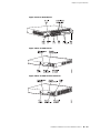
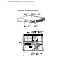
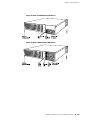
J4350 and J6350 Services Router Hardware Features ....................................26
J4350 and J6350 Chassis .........................................................................27
J4350 and J6350 Midplane ......................................................................31
J4350 and J6350 Routing Engine Hardware ............................................31
J4350 and J6350 Boot Devices ................................................................31
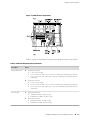
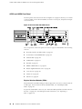
J4350 and J6350 Front Panel ..................................................................32
Physical Interface Modules (PIMs) ....................................................32
Power Button and POWER LED ........................................................33
STATUS LED .....................................................................................34
ALARM LED ......................................................................................34
HA LED ............................................................................................35
RESET CONFIG Button .....................................................................35
Built-In Gigabit Ethernet Ports ..........................................................35
Console Port .....................................................................................36
AUX Port ..........................................................................................36
USB Port ...........................................................................................36
J4350 Power System ...............................................................................36
J6350 Power System ...............................................................................37
J4350 and J6350 Cooling System ............................................................38
Software Overview ........................................................................................39
Routing Engine and Packet Forwarding Engine .......................................40
Kernel and Microkernel ..........................................................................40
JUNOS Software Processes ......................................................................40
User Interfaces ........................................................................................41
Chapter 3
PIM and VoIP Module Overview
43
PIM and VoIP Module Terms .........................................................................44
Field-Replaceable PIMs ..................................................................................46
J2320 and J2350 Field-Replaceable PIM Summary ..................................46
J4350 and J6350 Field-Replaceable PIM Summary ..................................47
1-Port, 6-Port, 8-Port, and 16-Port Gigabit Ethernet uPIMs ......................49
1-Port Gigabit Ethernet ePIMs .................................................................52
Dual-Port Serial PIM ................................................................................55
Dual-Port T1 or E1 PIM ...........................................................................56
Dual-Port Channelized T1/E1/ISDN PRI PIM ............................................57
T3 or E3 PIM ...........................................................................................59
Dual-Port Fast Ethernet PIM ....................................................................61
4-Port Fast Ethernet ePIM .......................................................................62
4-Port ISDN BRI PIMs ..............................................................................63
ADSL PIM ................................................................................................64
G.SHDSL PIM ..........................................................................................66
Avaya VoIP Modules ......................................................................................67
Avaya VoIP Module Summary .................................................................67
TGM550 Telephony Gateway Module ......................................................69
TIM510 E1/T1 Telephony Interface Module ............................................73
viii
■
Table of Contents
Table of Contents
TIM514 Analog Telephony Interface Module ...........................................74
TIM521 BRI Telephony Interface Module ................................................75
Chapter 4
Services Router User Interface Overview
79
User Interface Overview ................................................................................79
J-Web Overview ......................................................................................79
CLI Overview ..........................................................................................80
Before You Begin ...........................................................................................80
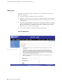
Using the J-Web Interface ..............................................................................81
Starting the J-Web Interface ....................................................................81
J-Web Layout ..........................................................................................82
Elements of the J-Web Interface ..............................................................83
Top Pane Elements ..........................................................................83
Main Pane Elements .........................................................................84
Side Pane Elements ..........................................................................85
Navigating the J-Web Interface ................................................................85
Navigating the Quick Configuration Pages ........................................86
Navigating the J-Web Configuration Editor .......................................86
Getting J-Web Help ...........................................................................87
J-Web Sessions ........................................................................................88
Using the Command-Line Interface ...............................................................89
CLI Command Hierarchy ........................................................................89
Starting the CLI .......................................................................................90
CLI Operational Mode .............................................................................90
CLI Configuration Mode ..........................................................................91
CLI Basics ...............................................................................................92
Editing Keystrokes ............................................................................92
Command Completion .....................................................................93
Online Help ......................................................................................94
Configuring the CLI Environment .....................................................95
Part 2
Installing a Services Router
Chapter 5
Preparing for Router Installation
101
General Site Guidelines ................................................................................101
Rack Requirements .....................................................................................102
Rack Size and Strength for J2320 and J2350 Routers ............................102
Rack Size and Strength for J4350 and J6350 Routers ............................103
Connection to Building Structure ..........................................................103
Router Environmental Tolerances ...............................................................104
Fire Safety Requirements ............................................................................104
Fire Suppression ...................................................................................104
Fire Suppression Equipment .................................................................105
Table of Contents
■
ix
J2320, J2350, J4350, and J6350 Services Router Getting Started Guide
Power Guidelines, Requirements, and Specifications ...................................105
Site Electrical Wiring Guidelines ............................................................106
Signaling Limitations ......................................................................106
Radio Frequency Interference ........................................................106
Electromagnetic Compatibility .......................................................106
Router Power Requirements .................................................................106
AC Power, Connection, and Power Cord Specifications ........................107
DC Power, Connection, and Power Cable Specifications .......................108
Planning for Power Management ..........................................................110
Network Cable Specifications ......................................................................112
ISDN Provisioning .......................................................................................112
Site Preparation Checklist ............................................................................112
Chapter 6
Installing and Connecting a Services Router
115
Before You Begin .........................................................................................115
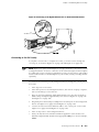
Unpacking a J-series Services Router ...........................................................116
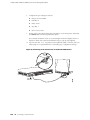
Installing J2320 and J2350 Routers .............................................................117
Installing J4350 and J6350 Routers .............................................................118
Connecting Interface Cables to Services Routers .........................................121
Chassis Grounding .......................................................................................121
Connecting Power .......................................................................................122
Connecting AC Power ...........................................................................122
Connecting DC Power ...........................................................................124
Powering a Services Router On and Off ......................................................127
Chapter 7
Establishing Basic Connectivity
129
Basic Connectivity Terms ............................................................................129
Basic Connectivity Overview .......................................................................130
Router Identification .............................................................................130
Root Password ......................................................................................131
Time Zone and System Time ................................................................131
Network Settings ...................................................................................132
Default Gateway ...................................................................................132
Backup Router ......................................................................................132
Loopback Address .................................................................................132
Built-In Ethernet Interface Address .......................................................133
Management Access .............................................................................133
Before You Begin .........................................................................................134
Connecting to a Services Router ..................................................................135
Connecting to the J-Web Interface ........................................................135
Connecting to the CLI Locally ................................................................137
Connecting to the CLI Remotely ...........................................................139
Configuring the Modem at the Router End .....................................139
Connecting the Modem to the Console Port ...................................140
Connecting to the CLI at the User End ............................................141
Configuring Basic Settings with J-Web Quick Configuration .........................141
x
■
Table of Contents
Table of Contents
Configuring Basic Settings with a Configuration Editor ................................145
Verifying Basic Connectivity ........................................................................148
Displaying Basic Connectivity Configurations .......................................149
Chapter 8
Configuring Secure Web Access
151
Secure Web Access Terms ...........................................................................151
Secure Web Access Overview ......................................................................152
Before You Begin .........................................................................................152
Generating SSL Certificates ...................................................................153
Configuring Secure Web Access ..................................................................153
Configuring Secure Web Access with a Configuration Editor .......................156
Verifying Secure Web Access ......................................................................157
Displaying an SSL Certificate Configuration ..........................................158
Displaying a Secure Access Configuration .............................................159
Chapter 9
Installing and Managing J-series Licenses
161
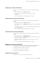
J-series License Overview ............................................................................161
Software Feature Licenses ....................................................................161
License Key Components ......................................................................162
Before You Begin .........................................................................................162
Managing J-series Licenses with the J-Web Interface ...................................163
Adding New Licenses with the J-Web Interface .....................................164
Deleting Licenses with the J-Web Interface ...........................................165
Displaying License Keys with the J-Web Interface .................................165
Downloading Licenses with the J-Web Interface ....................................165
Managing J-series Licenses with the CLI ......................................................165
Adding New Licenses with the CLI ........................................................165
Deleting a License with the CLI .............................................................166
Saving License Keys with the CLI ..........................................................166
Verifying J-series License Management ........................................................167
Displaying Installed Licenses ................................................................168
Displaying License Usage ......................................................................169
Displaying Installed License Keys .........................................................169
Part 3
Maintaining Services Router Hardware
Chapter 10
Replacing Hardware Components
173
Tools and Parts Required ............................................................................173
Replacing the Console Port Cable ................................................................174
Replacing a PIM ..........................................................................................174
Removing a PIM ...................................................................................174
Installing a PIM .....................................................................................176
Table of Contents
■
xi
J2320, J2350, J4350, and J6350 Services Router Getting Started Guide
Replacing PIM Cables ..................................................................................177
Removing PIM Cables ...........................................................................177
Installing PIM Cables .............................................................................177
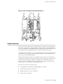
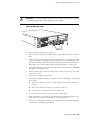
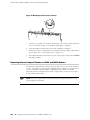
Removing and Replacing the Chassis Cover on J2320 and J2350 Routers ....178
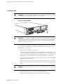
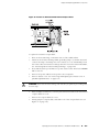
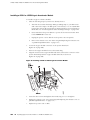
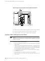
Replacing Internal Compact Flashes on J2320 and J2350 Routers ...............180
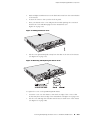
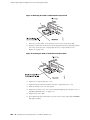
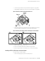
Replacing Internal Compact Flashes on J4350 and J6350 Routers ...............183
Replacing External Compact Flashes ...........................................................186
Replacing USB Storage Devices ...................................................................188
Removing the USB Storage Device ........................................................188
Installing the USB Storage Device .........................................................189
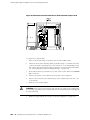
Replacing DRAM Modules ...........................................................................190
Removing a DRAM Module ...................................................................191
Installing a DRAM Module .....................................................................192
Replacing Power System Components ........................................................193
Replacing AC Power Supply Cords ........................................................193
Removing an AC Power Supply from J6350 Routers .............................194
Installing an AC Power Supply in J6350 Routers ...................................195
Replacing DC Power Supply Cables .......................................................196
Removing a DC Power Supply ..............................................................197
Installing a DC Power Supply ................................................................198
Replacing Crypto Accelerator Modules on J2320 and J2350 Routers ...........200
Removing a J2320 or J2350 Crypto Accelerator Module ........................201
Installing a J2320 or J2350 Crypto Accelerator Module .........................202
Replacing Crypto Accelerator Modules on J4350 and J6350 Routers ...........203
Removing a J4350 or J6350 Crypto Accelerator Module ........................204
Installing a J4350 or j6350 Crypto Accelerator Module .........................205
Replacing Air Filters on J2350 Routers ........................................................207
Replacing Air Filters on J4350 and J6350 Routers .......................................208
Chapter 11
Troubleshooting Hardware Components
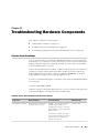
211
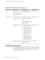
Chassis Alarm Conditions ............................................................................211
Troubleshooting Power Management ..........................................................212
Contacting the Juniper Networks Technical Assistance Center .....................214
Chapter 12
Contacting Customer Support and Returning Hardware
215
Locating Component Serial Numbers ..........................................................215
J2320 and J2350 Chassis Serial Number and Agency Labels .................216
J4350 and J6350 Chassis Serial Number and Agency Labels .................217
PIM Serial Number Label ......................................................................218
Power Supply Serial Number Labels ......................................................218
Contacting Customer Support ......................................................................218
Information You Might Need to Supply to JTAC ....................................219
Return Procedure ........................................................................................219
Packing a Router or Component for Shipment ............................................220
Tools and Parts Required ......................................................................220
Packing the Services Router for Shipment ............................................220
Packing Components for Shipment .......................................................221
xii
■
Table of Contents
Table of Contents
Part 4
J-series Requirements and Specifications
Chapter 13
Network Cable Specifications and Connector Pinouts
225
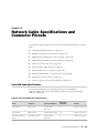
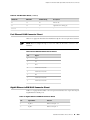
Serial PIM Cable Specifications ....................................................................225
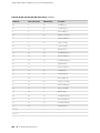
RS-232 DTE Cable Pinout ......................................................................226
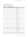
RS-232 DCE Cable Pinout .....................................................................227
RS-422/449 (EIA-449) DTE Cable Pinout ...............................................227
RS-422/449 (EIA-449) DCE Cable Pinout ...............................................229
EIA-530A DTE Cable Pinout ..................................................................230
EIA-530A DCE Cable Pinout ..................................................................231
V.35 DTE Cable Pinout ..........................................................................232
V.35 DCE Cable Pinout .........................................................................233
X.21 DTE Cable Pinout .........................................................................233
X.21 DCE Cable Pinout .........................................................................234
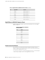
Fast Ethernet RJ-45 Connector Pinout .........................................................235
Gigabit Ethernet uPIM RJ-45 Connector Pinout ............................................235
Gigabit Ethernet ePIM RJ-45 Connector Pinout ............................................236
Chassis Console Port Pinouts .......................................................................236
E1 and T1 RJ-48 Cable Pinouts ....................................................................237
E3 and T3 BNC Connector Pinout ................................................................240
ADSL and G.SHDSL RJ-11 Connector Pinout ................................................240
ISDN RJ-45 Connector Pinout ......................................................................241
Connector Pinouts for Avaya VoIP Modules .................................................241
TGM550 Console Port Pinouts ..............................................................241
TGM550 RJ-11 Connector Pinout for Analog Ports ................................242
TIM510 RJ-45 Connector Pinout ............................................................243
TIM514 Connector Pinout .....................................................................243
TIM521 Connector Pinout .....................................................................243
Chapter 14
Safety and Regulatory Compliance Information
245
Definition of Safety Warning Levels ............................................................245
Safety Guidelines and Warnings ..................................................................247
General Safety Guidelines and Warnings ...............................................247
Qualified Personnel Warning ..........................................................248
Preventing Electrostatic Discharge Damage ...................................249
Electrical Safety Guidelines and Warnings ............................................249
General Electrical Safety Guidelines ................................................250
AC Power Electrical Safety Guidelines ............................................251
DC Power Electrical Safety Guidelines ............................................252
Power Sources for Redundant Power Supplies ...............................252
DC Power Disconnection Warning .................................................253
DC Power Grounding Requirements and Warning ..........................254
DC Power Wiring Sequence Warning .............................................255
DC Power Wiring Terminations Warning .......................................256
Grounded Equipment Warning .......................................................258
Warning Statement for Norway and Sweden ..................................258
In Case of Electrical Accident .........................................................259
Table of Contents
■
xiii
J2320, J2350, J4350, and J6350 Services Router Getting Started Guide
Multiple Power Supplies Disconnection Warning ............................259
Power Disconnection Warning .......................................................260
TN Power Warning .........................................................................261
Telecommunication Line Cord Warning .........................................262
Installation Safety Guidelines and Warnings .........................................263
Chassis Lifting Guidelines ...............................................................263
Installation Instructions Warning ....................................................264
Rack-Mounting Requirements and Warnings ..................................264
Ramp Warning ...............................................................................268
Laser and LED Safety Guidelines and Warnings ....................................269
General Laser Safety Guidelines ......................................................269
Class 1 Laser Product Warning .......................................................269
Class 1 LED Product Warning .........................................................270
Laser Beam Warning ......................................................................270
Radiation from Open Port Apertures Warning ................................271
Maintenance and Operational Safety Guidelines and Warnings ............273
Battery Handling Warning ..............................................................273
Jewelry Removal Warning ..............................................................274
Lightning Activity Warning .............................................................276
Operating Temperature Warning ....................................................277
Product Disposal Warning ..............................................................278
Agency Approvals ........................................................................................279
Compliance Statements for Environmental Requirements ..........................280
Lithium Battery .....................................................................................280
Compliance Statements for EMC Requirements ..........................................280
Canada .................................................................................................281
European Community ...........................................................................282
Japan ....................................................................................................283
United States ........................................................................................284
FCC Part 15 Statement ...................................................................284
FCC Part 68 Statement ...................................................................284
Part 5
Index
Index ...........................................................................................................289
xiv
■
Table of Contents
About This Guide
This preface provides the following guidelines for using the J2320, J2350, J4350, and
J6350 Services Router Getting Started Guide:
■
Objectives on page xv
■
Audience on page xv
■
How to Use This Guide on page xvi
■
Document Conventions on page xvii
■
Related Juniper Networks Documentation on page xviii
■
Documentation Feedback on page xxi
■
Requesting Support on page xxi
Objectives
This guide contains an overview, basic instructions, and specifications for J2320,
J2350, J4350, and J6350 Services Routers. It explains how to prepare your site for
installation, unpack and install a Services Router and its components, power on the
router, install licenses, and establish basic connectivity.
J-series Services Router operations are controlled by the JUNOS Internet software.
You direct the JUNOS software through either a Web browser or a command-line
interface (CLI).
NOTE: This guide documents Release 8.4 of the JUNOS software. For additional
information about J-series Services Routers—either corrections to or omissions from
this guide—see the J-series Services Router Release Notes at http://www.juniper.net.
Audience
This guide is designed for anyone who installs and sets up a J-series Services Router
or prepares a site for Services Router installation. The guide is intended for the
following audiences:
■
Customers with technical knowledge of and experience with networks and the
Internet
Objectives
■
xv
J2320, J2350, J4350, and J6350 Services Router Getting Started Guide
■
Network administrators who install, configure, and manage Internet routers but
are unfamiliar with the JUNOS software
■
Network administrators who install, configure, and manage products of Juniper
Networks
Personnel operating the equipment must be trained and competent; must not conduct
themselves in a careless, willfully negligent, or hostile manner; and must abide by
the instructions provided by the documentation.
How to Use This Guide
J-series documentation explains how to install, configure, and manage J-series routers
by providing information about JUNOS implementation specifically on J-series routers.
(For comprehensive JUNOS information, see the JUNOS software manuals listed in
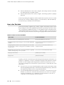
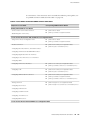
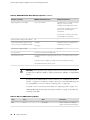
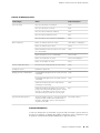
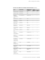
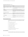
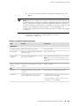
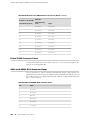
“Related Juniper Networks Documentation” on page xviii.) Table 1 on page xvi shows
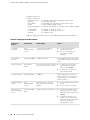
the location of J-series information, by task type, in Juniper Networks documentation.
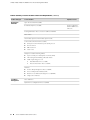
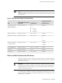
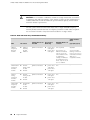
Table 1: Location of J-series Information
J-series Tasks
Location of Instruction
Installing hardware and establishing basic connectivity
Getting Started Guide for your router
Configuring interfaces and routing protocols such as RIP, OSPF, BGP,
and IS-IS
J-series Services Router Basic LAN and WAN Access
Configuration Guide
Configuring advanced features such as virtual private networks (VPNs),
IP Security (IPSec), multicast, routing policies, firewall filters, and class
of service (CoS)
J-series Services Router Advanced WAN Access
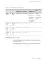
Configuration Guide
Managing users and operations, monitoring performance, upgrading
software, and diagnosing common problems
J-series Services Router Administration Guide
Using the J-Web interface
J-Web Interface User Guide
Using the CLI
JUNOS CLI User Guide
Typically, J-series documentation provides both general and specific information—for
example, a configuration overview, configuration examples, and verification methods.
Because you can configure and manage J-series routers in several ways, you can
choose from multiple sets of instructions to perform a task. To make best use of this
information:
xvi
■
■
If you are new to the topic—Read through the initial overview information, keep
the related JUNOS guide handy for details about the JUNOS hierarchy, and follow
the step-by-step instructions for your preferred interface.
■
If you are already familiar with the feature—Go directly to the instructions for the
interface of your choice, and follow the instructions. You can choose a J-Web
method, the JUNOS CLI, or a combination of methods based on the level of
complexity or your familiarity with the interface.
How to Use This Guide
About This Guide
For many J-series features, you can use J-Web Quick Configuration pages to configure
the router quickly and easily without configuring each statement individually. For
more extensive configuration, use the J-Web configuration editor or CLI configuration
mode commands.
To monitor, diagnose, and manage a router, use the J-Web interface or CLI operational
mode commands.
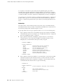
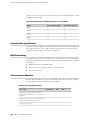
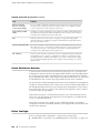
Document Conventions
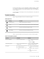
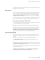
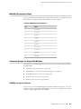
Table 2 on page xvii defines the notice icons used in this guide.
Table 2: Notice Icons
Icon
Meaning
Description
Informational note
Indicates important features or instructions.
Caution
Indicates a situation that might result in loss of data or hardware damage.
Warning
Alerts you to the risk of personal injury or death.
Laser warning
Alerts you to the risk of personal injury from a laser.
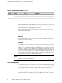
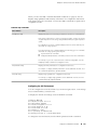
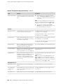
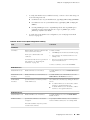
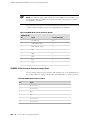
Table 3 on page xvii defines the text and syntax conventions used in this guide.
Table 3: Text and Syntax Conventions
Convention
Description
Examples
Bold sans serif typeface
Represents text that you type.
To enter configuration mode, type the
configure command:
user@host> configure
Fixed-width typeface
Represents output that appears on the
terminal screen.
Italic typeface
■
Introduces important new terms.
■
Identifies book names.
■
Identifies RFC and Internet draft
titles.
user@host> show chassis alarms
No alarms currently active
■
A policy term is a named structure
that defines match conditions and
actions.
■
JUNOS System Basics Configuration
Guide
■
RFC 1997, BGP Communities
Attribute
Document Conventions
■
xvii
J2320, J2350, J4350, and J6350 Services Router Getting Started Guide
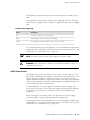
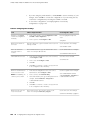
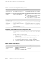
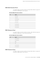
Table 3: Text and Syntax Conventions (continued)
Convention
Description
Examples
Italic sans serif typeface
Represents variables (options for which
you substitute a value) in commands or
configuration statements.
Configure the machine’s domain name:
Represents names of configuration
statements, commands, files, and
directories; IP addresses; configuration
hierarchy levels; or labels on routing
platform components.
■
< > (angle brackets)
Enclose optional keywords or variables.
stub <default-metric metric>;
| (pipe symbol)
Indicates a choice between the mutually
exclusive keywords or variables on either
side of the symbol. The set of choices is
often enclosed in parentheses for clarity.
broadcast | multicast
# (pound sign)
Indicates a comment specified on the
same line as the configuration statement
to which it applies.
rsvp { # Required for dynamic MPLS only
[ ] (square brackets)
Enclose a variable for which you can
substitute one or more values.
community name members [
community-ids ]
Indention and braces ( { } )
Identify a level in the configuration
hierarchy.
; (semicolon)
Identifies a leaf statement at a
configuration hierarchy level.
Sans serif typeface
[edit]
root@# set system domain-name
domain-name
To configure a stub area, include
the stub statement at the [edit
protocols ospf area area-id]
hierarchy level.
■
The console port is labeled
CONSOLE.
(string1 | string2 | string3)
[edit]
routing-options {
static {
route default {
nexthop address;
retain;
}
}
}
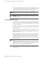
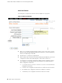
J-Web GUI Conventions
Bold typeface
Represents J-Web graphical user
interface (GUI) items you click or select.
> (bold right angle bracket)
Separates levels in a hierarchy of J-Web
selections.
■
In the Logical Interfaces box, select
All Interfaces.
■
To cancel the configuration, click
Cancel.
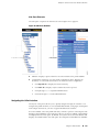
In the configuration editor hierarchy,
select Protocols>Ospf.
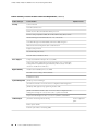
Related Juniper Networks Documentation
J-series Services Routers are documented in multiple guides. Although the J-series
guides provide instructions for configuring and managing a Services Router with the
JUNOS CLI, they are not a comprehensive JUNOS software resource. For complete
xviii
■
Related Juniper Networks Documentation
About This Guide
documentation of the statements and commands described in J-series guides, see
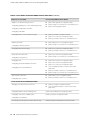
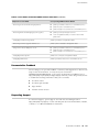
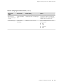
the JUNOS software manuals listed in Table 4 on page xix.
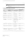
Table 4: J-series Guides and Related JUNOS Software Publications
Chapter in a J-series Guide
Corresponding JUNOS Software Manual
Getting Started Guide for Your Router
“Services Router User Interface Overview”
■
JUNOS CLI User Guide
■
JUNOS System Basics Configuration Guide
“Establishing Basic Connectivity”
J-series Services Router Basic LAN and WAN Access Configuration Guide
“Using Services Router Configuration Tools”
“Interfaces Overview”
■
JUNOS CLI User Guide
■
JUNOS System Basics Configuration Guide
■
JUNOS Network Interfaces Configuration Guide
■
JUNOS Interfaces Command Reference
■
JUNOS Services Interfaces Configuration Guide
■
JUNOS System Basics and Services Command Reference
■
JUNOS Network Interfaces Configuration Guide
■
JUNOS Interfaces Command Reference
■
JUNOS Network Interfaces Configuration Guide
■
JUNOS System Basics Configuration Guide
■
JUNOS System Basics and Services Command Reference
■
JUNOS Routing Protocols Configuration Guide
■
JUNOS Routing Protocols and Policies Command Reference
“Configuring DS1, DS3, Ethernet, and Serial Interfaces”
“Configuring Channelized T1/E1/ISDN PRI Interfaces”
“Configuring Digital Subscriber Line Interfaces
“Configuring Point-to-Point Protocol over Ethernet”
“Configuring ISDN”
“Configuring Link Services Interfaces”
“Configuring VoIP”
“Configuring uPIMs as Ethernet Switches”
“Routing Overview”
“Configuring Static Routes”
“Configuring a RIP Network”
“Configuring an OSPF Network”
“Configuring the IS-IS Protocol”
“Configuring BGP Sessions”
J-series Services Router Advanced WAN Access Configuration Guide
Related Juniper Networks Documentation
■
xix
J2320, J2350, J4350, and J6350 Services Router Getting Started Guide
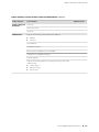
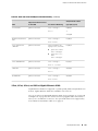
Table 4: J-series Guides and Related JUNOS Software Publications (continued)
Chapter in a J-series Guide
Corresponding JUNOS Software Manual
“Multiprotocol Label Switching Overview”
■
JUNOS MPLS Applications Configuration Guide
■
JUNOS Routing Protocols and Policies Command Reference
■
JUNOS VPNs Configuration Guide
■
JUNOS System Basics Configuration Guide
■
JUNOS Services Interfaces Configuration Guide
■
JUNOS System Basics and Services Command Reference
■
JUNOS Multicast Protocols Configuration Guide
■
JUNOS Routing Protocols and Policies Command Reference
■
JUNOS Services Interfaces Configuration Guide
■
JUNOS System Basics and Services Command Reference
■
JUNOS Policy Framework Configuration Guide
■
JUNOS Routing Protocols and Policies Command Reference
■
JUNOS Network Interfaces Configuration Guide
■
JUNOS Policy Framework Configuration Guide
■
JUNOS Services Interfaces Configuration Guide
■
Secure Configuration Guide for Common Criteria and
JUNOS-FIPS
■
JUNOS System Basics and Services Command Reference
■
JUNOS Routing Protocols and Policies Command Reference
■
JUNOS Class of Service Configuration Guide
■
JUNOS System Basics and Services Command Reference
■
JUNOS System Basics Configuration Guide
■
Secure Configuration Guide for Common Criteria and
JUNOS-FIPS
“Configuring Signaling Protocols for Traffic Engineering”
“Configuring Virtual Private Networks”
“Configuring CLNS VPNs”
“Configuring IPSec for Secure Packet Exchange”
“Multicast Overview”
“Configuring a Multicast Network”
“Configuring Data Link Switching”
“Policy Framework Overview”
“Configuring Routing Policies”
“Configuring NAT”
“Configuring Stateful Firewall Filters and NAT”
“Configuring Stateless Firewall Filters”
“Class-of-Service Overview”
“Configuring Class of Service”
J-series Services Router Administration Guide
“Managing User Authentication and Access”
“Configuring SNMP for Network Management”
JUNOS Network Management Configuration Guide
“Configuring the Router as a DHCP Server”
JUNOS System Basics Configuration Guide
“Configuring Autoinstallation”
“Automating Network Operations and Troubleshooting”
xx
■
Related Juniper Networks Documentation
JUNOS Configuration and Diagnostic Automation Guide
About This Guide
Table 4: J-series Guides and Related JUNOS Software Publications (continued)
Chapter in a J-series Guide
Corresponding JUNOS Software Manual
“Monitoring the Router and Routing Operations”
■
JUNOS System Basics and Services Command Reference
■
JUNOS Interfaces Command Reference
■
JUNOS Routing Protocols and Policies Command Reference
■
JUNOS System Log Messages Reference
■
Secure Configuration Guide for Common Criteria and
JUNOS-FIPS
“Monitoring Events and Managing System Log Files”
“Configuring and Monitoring Alarms”
JUNOS System Basics Configuration Guide
“Performing Software Upgrades and Reboots”
JUNOS Software Installation and Upgrade Guide
“Using Services Router Diagnostic Tools”
■
JUNOS System Basics and Services Command Reference
■
JUNOS Interfaces Command Reference
■
JUNOS Routing Protocols and Policies Command Reference
“Configuring Packet Capture”
JUNOS Services Interfaces Configuration Guide
“Configuring RPM Probes”
JUNOS System Basics and Services Command Reference
Documentation Feedback
We encourage you to provide feedback, comments, and suggestions so that we can
improve the documentation. You can send your comments to
[email protected], or fill out the documentation feedback form at
http://www.juniper.net/techpubs/docbug/docbugreport.html. If you are using e-mail, be sure
to include the following information with your comments:
■
Document name
■
Document part number
■
Page number
■
Software release version
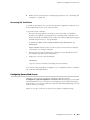
Requesting Support
For technical support, open a support case with the Case Manager link at
http://www.juniper.net/support/ or call 1-888-314-JTAC (from the United States, Canada,
or Mexico) or 1-408-745-9500 (from elsewhere).
Documentation Feedback
■
xxi
J2320, J2350, J4350, and J6350 Services Router Getting Started Guide
xxii
■
Requesting Support
Part 1
J-series Overview
■
Overview of Services Routers on page 3
■
System Overview on page 13
■
PIM and VoIP Module Overview on page 43
■
Services Router User Interface Overview on page 79
J-series Overview
■
1
J2320, J2350, J4350, and J6350 Services Router Getting Started Guide
2
■
J-series Overview
Chapter 1
Overview of Services Routers
J-series Services Routers provide stable, reliable, and efficient IP routing, WAN and
LAN connectivity, and management services for small to medium-sized enterprise
networks. Services Routers typically connect small, branch, or regional offices to a
central site router, and link Internet service provider (ISP) networks.
All J-series Services Routers run the JUNOS Internet software, which offers many
advanced routing and security services. For more information about software features,
see “J-series Software Features and Licenses” on page 7. A single, common JUNOS
code base simplifies deployment, patches, and software upgrades.
You can use two user interfaces to monitor, configure, troubleshoot, and manage a
Services Router:
■
J-Web interface—A Web-based graphical interface that allows you to operate a
router without commands. The J-Web interface provides access to all JUNOS
functionality and features. Quick Configuration wizards simplify basic
configuration and minimize the risk of operator error.
■
JUNOS command-line interface—A Juniper Networks command shell that runs
on top of a UNIX-based operating system kernel. The CLI is a straightforward
command interface. On a single line, you type commands that are executed
when you press the Enter key. The CLI provides command Help and command
completion.
For an introduction to the J-Web and CLI interfaces, see “Services Router User
Interface Overview” on page 79. For more information, see the J-Web Interface User
Guide and the JUNOS CLI User Guide.
This chapter contains the following topics:
■
J2320 Services Router Overview on page 4
■
J2350 Services Router Overview on page 4
■
J4350 Services Router Overview on page 5
■
J6350 Services Router Overview on page 6
■
J-series Software Features and Licenses on page 7
■
3
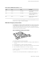
J2320, J2350, J4350, and J6350 Services Router Getting Started Guide
J2320 Services Router Overview
The J2320 Services Router is primarily designed for remote or branch offices. It has
a small chassis that is 1 U (rack unit) in size with a nonredundant AC power supply,
an external compact flash and two universal serial bus (USB) ports for external storage,
and an optional Crypto Accelerator Module.
J2320 routers ordered with the optional Crypto Accelerator Module come standard
with 1 GB of memory, while those ordered without the Crypto Accelerator Module
come standard with 256 MB of memory. The memory on J2320 routers can be
upgraded to 1 GB. For instructions on upgrading memory, see “Replacing DRAM
Modules” on page 190.
Each J2320 chassis contains four built-in Gigabit Ethernet ports with link speeds of
10/100/1000 Mbps over a copper interface. The chassis also contains three slots for
field-replaceable Physical Interface Modules (PIMs) and Avaya voice over IP (VoIP)
modules providing flexible WAN and voice connectivity options.
The J2320 Services Router supports the following field-replaceable PIMs and Avaya
VoIP modules:
■
Gigabit Ethernet uPIM (1-port, 6-port, 8-port, and 16-port)
■
Dual-Port Serial PIM
■
Dual-Port E1 PIM
■
Dual-Port T1 PIM
■
Dual-Port Channelized T1/E1/ISDN PRI PIM
■
4-port ISDN BRI S/T or U PIM
■
ADSL 2/2+ Annex A PIM (1 port)
■
ADSL 2/2+ Annex B PIM (1 port)
■
G.SHDSL PIM (2 ports)
■
TGM550 Telephony Gateway Module
■
TIM510 E1/T1 Telephony Interface Module (1 port)
■
TIM514 Analog Telephony Interface Module (4 ports)
■
TIM521 BRI Telephony Interface Module (4 ports)
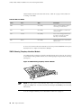
J2350 Services Router Overview
The J2350 Services Router is primarily designed for regional or branch offices. It has
a chassis that is 1.5 U (rack unit) in size with a nonredundant AC or DC power supply,
an external compact flash and two universal serial bus (USB) ports for external storage,
and an optional Crypto Accelerator Module.
J2350 routers ordered with the optional Crypto Accelerator Module come standard
with 1 GB of memory, while those ordered without the Crypto Accelerator Module
come standard with 256 MB of memory. The memory on J2350 routers can be
4
■
J2320 Services Router Overview
Chapter 1: Overview of Services Routers
upgraded to 1 GB. For instructions on upgrading memory, see “Replacing DRAM
Modules” on page 190.
Each J2350 chassis contains four built-in Gigabit Ethernet ports with link speeds of
10/100/1000 Mbps over a copper interface. The chassis also contains five slots for
field-replaceable Physical Interface Modules (PIMs) and Avaya VoIP modules providing
flexible WAN and voice connectivity options.
The J2350 Services Router supports the following field-replaceable PIMs and Avaya
VoIP modules:
■
Gigabit Ethernet uPIM (1–port, 6-port, 8-port, and 16-port)
■
Dual-Port Serial PIM
■
Dual-Port E1 PIM
■
Dual-Port T1 PIM
■
Dual-Port Channelized T1/E1/ISDN PRI PIM
■
4-port ISDN BRI S/T or U PIM
■
ADSL 2/2+ Annex A PIM (1 port)
■
ADSL 2/2+ Annex B PIM (1 port)
■
G.SHDSL PIM (2 ports)
■
TGM550 Telephony Gateway Module
■
TIM510 E1/T1 Telephony Interface Module (1 port)
■
TIM514 Analog Telephony Interface Module (4 ports)
■
TIM521 ISDN BRI Telephony Interface Module (4 ports)
J4350 Services Router Overview
The J4350 Services Router is designed primarily for regional or branch offices. It has
a chassis that is 2 U (rack units) in size with a nonredundant AC or DC power supply,
and a universal serial bus (USB) port for external storage.
J4350 routers ordered with the optional Crypto Accelerator Module come standard
with 1 GB of memory, while those ordered without the Crypto Accelerator Module
come standard with 256 MB of memory. J4350 routers can contain between 256
MB and 2 GB of memory. For instructions on adding memory, see “Replacing DRAM
Modules” on page 190.
Each J4350 chassis contains four built-in Gigabit Ethernet ports with link speeds of
10/100/1000 Mbps over a copper interface, and six slots for field-replaceable Physical
Interface Modules (PIMs) and Avaya VoIP modules. Two of the six slots (slots 3 and
6) support high-speed interfaces (ePIMs).
The J4350 Services Router supports the following field-replaceable PIMs and Avaya
VoIP modules:
J4350 Services Router Overview
■
5
J2320, J2350, J4350, and J6350 Services Router Getting Started Guide
■
Gigabit Ethernet uPIM (1-port, 6-port, 8-port, and 16-port)
■
SFP Gigabit Ethernet ePIM (1 port)
■
Copper Gigabit Ethernet ePIM (1 port)
■
Dual-Port Serial PIM
■
Dual-Port E1 PIM
■
Dual-Port T1 PIM
■
Dual-Port Channelized T1/E1/ISDN PRI PIM
■
E3 PIM (1 port)
■
DS3 (T3) PIM (1 port)
■
Dual-Port Fast Ethernet PIM
■
4-port Fast Ethernet ePIM
■
4-port ISDN BRI S/T or U PIM
■
ADSL 2/2+ Annex A PIM (1 port)
■
ADSL 2/2+ Annex B PIM (1 port)
■
G.SHDSL PIM (2 ports)
■
TGM550 Telephony Gateway Module
■
TIM510 E1/T1 Telephony Interface Module (1 port)
■
TIM514 Analog Telephony Interface Module (4 ports)
■
TIM521 ISDN BRI Telephony Interface Module (4 ports)
J6350 Services Router Overview
The J6350 Services Router is designed primarily for regional or central offices. It has
a chassis that is 2 U (rack units) in size with an optional redundant AC or DC power
supply, up to 2 GB of memory, and two universal serial bus (USB) ports for external
storage. The J6350 Services Router is a higher-performance system than the J4350
Services Router.
J6350 routers come standard with 1 GB of memory and can be upgraded to 2 GB of
memory. For instructions on adding memory, see “Replacing DRAM
Modules” on page 190.
Each J6350 chassis contains four built-in Gigabit Ethernet ports with link speeds of
10/100/1000 Mbps over a copper interface, and six slots for field-replaceable Physical
Interface Modules (PIMs) and Avaya VoIP modules. Four of the six slots (slots 2, 3,
5, and 6) support high-speed interfaces (ePIMs).
The J6350 Services Router supports the following field-replaceable PIMs and Avaya
VoIP modules:
6
■
■
Gigabit Ethernet uPIM (1–port, 6-port, 8-port, and 16-port)
■
SFP Gigabit Ethernet ePIM (1 port)
J6350 Services Router Overview
Chapter 1: Overview of Services Routers
■
Copper Gigabit Ethernet ePIM (1 port)
■
ADSL 2/2+ Annex A PIM (1 port)
■
ADSL 2/2+ Annex B PIM (1 port)
■
Dual-Port E1 PIM
■
E3 PIM (1 port)
■
DS3 (T3) PIM (1 port)
■
Dual-Port Fast Ethernet PIM
■
Dual-Port Channelized T1/E1/ISDN PRI PIM
■
4-port Fast Ethernet ePIM
■
G.SHDSL PIM (2 ports)
■
4-port ISDN BRI S/T or U PIM
■
Dual-Port Serial PIM
■
Dual-Port T1 PIM
■
TGM550 Telephony Gateway Module
■
TIM510 E1/T1 Telephony Interface Module (1 port)
■
TIM514 Analog Telephony Interface Module (4 ports)
■
TIM521 ISDN BRI Telephony Interface Module (4 ports)
J-series Software Features and Licenses
J-series Services Routers provide the software features listed in Table 5 on page 7.
You must purchase a separate software license to obtain some software features.
For more information about licenses, see “Installing and Managing J-series
Licenses” on page 161.
Table 5: Summary of J-series Features and License Requirements
Feature Category
J-series Feature
Internet Protocols
IPv4
Separate License
IPv6 routing and forwarding
J-series Software Features and Licenses
■
7
J2320, J2350, J4350, and J6350 Services Router Getting Started Guide
Table 5: Summary of J-series Features and License Requirements (continued)
Feature Category
J-series Feature
Routing and
Multicast
Open Shortest Path First (OSPF)
Border Gateway Protocol (BGP)
Routing Information Protocol version 1 (RIPv1) and RIPv2
Static routes
Intermediate System-to-Intermediate System (IS-IS)
Connectionless Network Services (CLNS):
■
End system-to-Intermediate system (ES-IS) protocol
■
IS-IS extensions
■
BGP extensions
■
Static routes
Multiprotocol Label Switching (MPLS):
■
Layer 2 and Layer 3 virtual private networks (VPNs)
■
VPN routing and forwarding (VRF) table labels
■
Traffic engineering protocols:
■
Label Distribution Protocol (LDP)
■
Resource Reservation Protocol (RSVP)
Multicast:
IP Address
Management
■
Internet Group Management Protocol (IGMP)
■
Protocol Independent Multicast (PIM)
■
Distance Vector Multicast Routing Protocol (DVMRP)
■
Single-source multicast
Static addresses
Dynamic Host Configuration Protocol (DHCP)
8
■
J-series Software Features and Licenses
Separate License
License required for
advanced BGP (route
reflectors)
Chapter 1: Overview of Services Routers
Table 5: Summary of J-series Features and License Requirements (continued)
Feature Category
J-series Feature
Encapsulation
Ethernet:
Separate License
■
Media access control (MAC) encapsulation
■
802.1p tagging
■
Point-to-Point Protocol over Ethernet (PPPoE)
■
Asynchronous Transfer Mode (ATM) for asymmetric digital subscriber
line (ADSL) or symmetric high-speed digital subscriber line (SHDSL)
■
Circuit cross-connect (CCC)
■
Translational cross-connect (TCC)
Synchronous Point-to-Point Protocol (PPP)
Frame Relay
High-level Data Link Control (HDLC)
Serial encapsulation over RS-232, RS-449, X.21, V.35, and EIA-530
connections
802.1Q filtering and forwarding
Multilink Frame Relay
Multilink PPP
Data link switching (DLSw)
Traffic Management
License required
Policing and shaping
Class-based queuing with prioritization
Weighted random early detection (WRED)
Queuing by virtual LAN (VLAN), data link connection identifier (DLCI),
interface, or bundle
Ethernet Switching
Access switching provided by multiport Gigabit Ethernet uPIMs
J-series Software Features and Licenses
■
9
J2320, J2350, J4350, and J6350 Services Router Getting Started Guide
Table 5: Summary of J-series Features and License Requirements (continued)
Feature Category
J-series Feature
Security
Common Criteria
Separate License
Network attack detection
Denial-of-service (DoS) and distributed DoS protection
Generic routing encapsulation (GRE), IP-over-IP, and IP Security (IPSec) tunnels
Advanced Encryption Standard (AES) 128-, 192-, and 256-bit.
56-bit Data Encryption Standard (DES) and 168-bit 3DES encryption
MD5 and Secure Hash Algorithm (SHA-1) authentication
Replay attack prevention
Stateful firewall packet filters
Network Address Translation (NAT)
Voice Support
Compressed Real-Time Transport Protocol (CRTP)
J2320, J2350, J4350, and J6350 Services Routers support voice over IP (VoIP)
routing with the Avaya IG550 Integrated Gateway, which consists of modules
that can be installed in the PIM slots.
High Availability
Virtual Router Redundancy Protocol (VRRP)
Graceful restart according to IETF standards
Redundant interfaces
System Management
JUNOScope network manager
J-Web browser interface—for Services Router configuration and management
JUNOScript XML application programming interface (API)
JUNOS command-line interface (CLI)—for Services Router configuration and
management through the console, Telnet, SSH, or J-Web CLI terminal
Simple Network Management Protocol version 1 (SNMPv1) and SNMPv2
Traffic Analysis
J-Flow flow monitoring and accounting
Packet capture (PCAP)
Real-time performance monitoring (RPM)
10
■
J-series Software Features and Licenses
License required for
J-Flow
Chapter 1: Overview of Services Routers
Table 5: Summary of J-series Features and License Requirements (continued)
Feature Category
J-series Feature
Activity Logging and
Monitoring
System log
Separate License
J-Web event viewer
Traceroute
Administration
Supports the following external administrator databases:
■
RADIUS
■
TACACS+
Autoinstallation
Configuration rollback
Button-operated configuration rescue (CONFIG)
Confirmation of configuration changes
Software upgrades
Supports the following features for automating network operations and
troubleshooting:
■
Commit scripts
■
Operation scripts
■
Event policies
J-series Software Features and Licenses
■
11
J2320, J2350, J4350, and J6350 Services Router Getting Started Guide
12
■
J-series Software Features and Licenses
Chapter 2
System Overview
J-series J2320, J2350, J4350, and J6350 Services Routers have chassis that are similar
but with important differences. J2320, J2350, and J4350 routers have a single
nonredundant power supply and an optional Crypto Accelerator Module. J6350
routers have redundant power supplies and a standard Crypto Accelerator Module.
For field-replaceable PIMs and Avaya VoIP modules, the J2320 has three slots, the
J2350 has five slots, and the J4350 and J6350 have six slots. Of the six slots, two on
the J4350 and four on the J6350 are enhanced (high-speed) slots.
All J-series routers run the JUNOS Internet software.
This chapter contains the following topics:
■
J2320 and J2350 Services Router Hardware Features on page 13
■
J4350 and J6350 Services Router Hardware Features on page 26
■
Software Overview on page 39
J2320 and J2350 Services Router Hardware Features
This section contains the following topics:
■
J2320 and J2350 Chassis on page 14
■
J2320 and J2350 Midplane on page 18
■
J2320 and J2350 Routing Engine Hardware on page 18
■
J2320 and J2350 Boot Devices on page 19
■
J2320 and J2350 Front Panel on page 19
■
J2320 and J2350 External Compact Flashes on page 24
■
J2320 Power System on page 24
■
J2350 Power System on page 24
■
J2320 and J2350 Cooling System on page 25
J2320 and J2350 Services Router Hardware Features
■
13
J2320, J2350, J4350, and J6350 Services Router Getting Started Guide
J2320 and J2350 Chassis
The J2320 and J2350 chassis is a rigid sheet metal structure that houses all the other
router components (see Figure 1 on page 14 through Figure 7 on page 17). The
chassis can be installed in many types of racks or cabinets. For information about
acceptable rack types, see “Rack Requirements” on page 102.
In addition to the components described in subsequent sections, the chassis includes
the following components:
■
Mounting brackets—One pair of metal brackets can be mounted at the front or
center of the chassis for mounting the chassis in a rack or cabinet.
■
Earthing terminal—A protective earthing terminal and a PEM nut at the rear of
the chassis ensure safe dissipation of static electricity in all situations.
■
ESD point—One electrostatic discharge (ESD) point, a banana plug receptacle at
the front of the chassis, minimizes the risk of electrical discharge in potentially
hazardous environments.
CAUTION: Before removing or installing components of a functioning router, attach
an ESD strap to an ESD point and place the other end of the strap around your bare
wrist. Failure to use an ESD strap could result in damage to the router.
The router must be connected to earth ground during normal operation. The protective
earthing terminal on the rear of the chassis is provided to connect the router to
ground (see Figure 3 on page 15). Additional grounding is provided to an AC-powered
router when you plug its power supply into a grounded AC power receptacle.
For additional safety information, see “Safety and Regulatory Compliance
Information” on page 245.
Figure 1: Front of J2320 Chassis
14
■
J2320 and J2350 Services Router Hardware Features
Chapter 2: System Overview
Figure 2: Front of J2350 Chassis
Figure 3: Rear of J2320 Chassis
Figure 4: Rear of J2350 AC-Powered Chassis
J2320 and J2350 Services Router Hardware Features
■
15
J2320, J2350, J4350, and J6350 Services Router Getting Started Guide
Figure 5: Rear of J2350 DC-Powered Chassis
Figure 6: J2320 Hardware Components
16
■
J2320 and J2350 Services Router Hardware Features
Chapter 2: System Overview
Figure 7: J2350 Hardware Components
Table 6 on page 17 summarizes the physical specifications for the router chassis.
Table 6: J2320 and J2350 Physical Specifications
Description
Value
Chassis dimensions
■
■
Router weight
■
■
J2320 Services Router
■
1.75 in. (4.45 cm) high
■
17.51 in. (44.48 cm) wide—18.9 in. (48.01 cm) wide with mounting brackets attached
■
15.1 in. (38.35 cm) deep—plus 0.78 in. (1.98 cm) of hardware that protrudes from the
chassis front
J2350 Services Router
■
2.61 in. (6.63 cm) high
■
17.51 in. (44.48 cm) wide—18.9 in. (48.01 cm) wide with mounting brackets attached
■
15.1 in. (38.35 cm) deep—plus 0.78 in. (1.98 cm) of hardware that protrudes from the
chassis front
J2320 Services Router
■
Minimum (no PIMs): 14.8 lbs (6.7 kg)
■
Maximum (three PIMs): 15.9 lbs (7.2 kg)
J2350 Services Router
■
Minimum (no PIMs): 16.3 lbs (7.4 kg)
■
Maximum (five PIMs): 18.2 lbs (8.3 kg)
J2320 and J2350 Services Router Hardware Features
■
17
J2320, J2350, J4350, and J6350 Services Router Getting Started Guide
J2320 and J2350 Midplane
The J2320 and J2350 midplane is located in the center of the chassis and forms the
rear of the PIM card cage (see Figure 6 on page 16 and Figure 7 on page 17). You
install the PIMs into the midplane from the front of the chassis. Data packets are
transferred across the midplane from the PIM to the Routing Engine, and from the
Routing Engine across the midplane to the destination PIM.
A time-division multiplexing (TDM) bus in J2320 and J2350 routers provides support
for the Avaya VoIP module TGM550. The TGM550 converts the voice path from the
TDM bus to compressed or uncompressed and packetized VoIP on an Ethernet
connection. For more information, see “PIM and VoIP Module Overview” on page 43.
J2320 and J2350 Routing Engine Hardware
The Routing Engine consists of the following components. For more information,
see “Software Overview” on page 39.
■
Processor—Creates the packet forwarding switch fabric for the router and runs
JUNOS Internet software to maintain the router's routing tables and routing
protocols.
■
DRAM—Buffers incoming packets and provides storage for the routing and
forwarding tables and for other Routing Engine processes.
To view the amount of DRAM installed on your router, issue the show chassis
routing-engine command.
■
EPROM—Stores the serial number of the Routing Engine.
To view the serial number of the Routing Engine, issue either the show chassis
routing-engine command or the show chassis hardware command.
■
Crypto Accelerator Module—Processor card that enhances performance of
cryptographic algorithms used in IP security (IPSec) services. The cryptographic
algorithms supported include Advanced Encryption Standard (AES), Data
Encryption Standard (DES), triple DES (3DES), Hashed Message Authentication
Code-Message Digest 5 (HMAC-MD5), and HMAC-Secure Hash Algorithm 1
(SHA-1). The Crypto Module is an optional feature of J2320 and J2350 Services
Routers.
To determine whether there is a Crypto Accelerator Module installed on your
router, issue the show chassis hardware command.
■
Compact flash—Provides primary storage for software images, configuration
files, and microcode. J-series routers have a primary or internal compact flash
located on the system board. For information about replacing the internal
compact flash, see “Replacing Internal Compact Flashes on J2320 and J2350
Routers” on page 180.
J2320 and J2350 Services Routers also provide a slot in the rear of the chassis
into which you can insert an additional external compact flash. For information
about external compact flashes, see “J2320 and J2350 External Compact
Flashes” on page 24.
18
■
J2320 and J2350 Services Router Hardware Features
Chapter 2: System Overview
J2320 and J2350 Boot Devices
J2320 and J2350 Services Routers can boot from three devices:
■
Internal compact flash
■
External compact flash (also known as the removable compact flash)
■
USB storage device
Normally, a J2320 or J2350 Services Router boots from the internal compact flash.
If the internal compact flash fails, the router attempts to boot from the external
compact flash if it is installed. If the external compact flash is not present or fails,
the router attempts to boot from the USB storage device.
J2320 and J2350 Front Panel
The front panel of a J2320 or J2350 Services Router (see Figure 8 on page 19 and
Figure 9 on page 19) allows you to install or remove PIMs, view router status LEDs,
access the console port, and perform simple control functions.
Figure 8: Front of J2320 Chassis
Figure 9: Front of J2350 Chassis
The components of the front panel, are described in the following sections:
■
Physical Interface Modules (PIMs) on page 20
■
Power Button and POWER LED on page 20
J2320 and J2350 Services Router Hardware Features
■
19
J2320, J2350, J4350, and J6350 Services Router Getting Started Guide
■
STATUS LED on page 21
■
ALARM LED on page 21
■
HA LED on page 22
■
RESET CONFIG Button on page 22
■
Built-In Gigabit Ethernet Ports on page 23
■
Console Port on page 23
■
AUX Port on page 23
■
USB Port on page 24
Physical Interface Modules (PIMs)
Physical Interface Modules (PIMs) provide the physical connection to various network
media types. For information about individual PIMs, see “Field-Replaceable
PIMs” on page 46.
For pinouts of PIM cable connectors, see “Network Cable Specifications and Connector
Pinouts” on page 225. For PIM replacement instructions, see “Replacing a
PIM” on page 174.
The J2320 front panel has three slots and the J2350 front panel has five slots for
field-replaceable PIMs. These slots are numbered from top to bottom and from left
to right as shown in Figure 10 on page 20.
Slot 0 is a fixed interface module that contains four built-in Gigabit Ethernet ports.
For more information, see “Built-In Gigabit Ethernet Ports” on page 23.
Figure 10: Slot Number Diagram on J2320 and J2350
Power Button and POWER LED
The power button is located on the left side of the front panel (see
Figure 1 on page 14). You can use the power button to power the Services Router
on and off. When you power on the router, the Routing Engine boots as the power
supply completes its startup sequence.
The POWER LED is located to the upper left of the LED dashboard. Table 7 on page
21 describes the POWER LED.
20
■
J2320 and J2350 Services Router Hardware Features
Chapter 2: System Overview
Table 7: J2320 and J2350 POWER LED
Color
State
Description
Green
On steadily
Power is functioning correctly.
Blinking
Power button has been pressed and quickly released, and
the router is gracefully shutting down.
Off
Router is not receiving power.
Unlit
After the router is powered on, status indicators—such as LEDs on the front panel
and show chassis command output—can take up to 60 seconds to indicate that the
power supply is functioning normally. Ignore error indicators that appear during the
first 60 seconds.
If you need to power off the router after the Routing Engine finishes booting, use the
J-Web interface or the CLI to halt the Services Router first. For instructions, see the
J-series Services Router Administration Guide. Alternatively, you can press and release
the power button to gracefully shut down the router. For more information, see
“Powering a Services Router On and Off” on page 127.
STATUS LED
When the system is powered on, the STATUS LED changes from off to blinking green.
Startup takes approximately 90 seconds to complete. If you want to turn the system
off and on again, we recommend waiting a few seconds between shutting it down
and powering it back up. Table 8 on page 21 describes the STATUS LED.
Table 8: J2320 and J2350 STATUS LED
Color
State
Description
Green
Blinking
Router is starting up or performing diagnostics.
On steadily
Router is operating normally.
Blinking
Error has been detected.
Red
ALARM LED
The ALARM LED lights amber to indicate a minor condition that requires monitoring
or maintenance and lights red to indicate a major condition that can result in a system
shutdown. When the condition is corrected, the light turns off. Table 9 on page 22
describes the ALARM LED.
J2320 and J2350 Services Router Hardware Features
■
21
J2320, J2350, J4350, and J6350 Services Router Getting Started Guide
Table 9: J2320 and J2350 ALARM LED
Color
State
Description
Red
On steadily
Major alarm indicates a critical situation on the router that
has resulted from one of the following conditions. A red
alarm condition requires immediate action:
Yellow
Unlit
On steadily
Off
■
One or more hardware components have failed.
■
One or more hardware components have exceeded
temperature thresholds.
■
An alarm condition configured on an interface has
triggered a critical warning.
Minor alarm condition requires monitoring or maintenance:
■
Indicates a noncritical condition on the router that, if
left unchecked, might cause an interruption in service
or degradation in performance.
■
A missing rescue configuration or software license
generates an amber system alarm.
No alarms.
For information about alarm conditions and corrective actions, see “Chassis Alarm
Conditions” on page 211. For additional information, see the J-series Services Router
Administration Guide.
HA LED
The HA (high availability) LED is for future use. The LED lights when the router starts,
but otherwise remains unlit.
RESET CONFIG Button
Use the RESET CONFIG button to return the router to either the rescue configuration
or the factory default configuration. The button is recessed to prevent it from being
pressed accidentally. To press this button insert a small probe (such as a straightened
paper clip) into the pinhole on the front panel (see Figure 8 on page 19 and
Figure 9 on page 19).
For example, if someone inadvertently commits a configuration that denies
management access to a Services Router, you can delete the invalid configuration
and replace it with a rescue configuration by pressing the RESET CONFIG button. You
must have previously set the rescue configuration through the J-Web interface or the
CLI. The rescue configuration is a previously committed, valid configuration.
CAUTION: Pressing and holding the RESET CONFIG button for 15 seconds or
more—until the STATUS LED blinks red—deletes all configurations on the router,
including the backup configurations and rescue configuration, and loads and commits
the factory configuration.
22
■
J2320 and J2350 Services Router Hardware Features
Chapter 2: System Overview
You can change the default behavior of the RESET CONFIG button. For more
information, see the J-series Services Router Basic LAN and WAN Access Configuration
Guide.
Built-In Gigabit Ethernet Ports
Four built-in Gigabit Ethernet ports provide LAN connections over copper interfaces
to hubs, switches, local servers, and workstations. You can also designate an Ethernet
port for management traffic. When configuring one of these ports, you use the
interface name that corresponds to the port’s location. From left to right on the front
panel, the interface names for the ports are ge-0/0/0, ge-0/0/1, ge-0/0/2, and
ge-0/0/3.
For Gigabit Ethernet port pinout information, see “Gigabit Ethernet uPIM RJ-45
Connector Pinout” on page 235.
Each port has two LEDs, a TX/RX LED on the left side and a LINK LED on the right
side. Table 10 on page 23 describes the built-in Ethernet port LEDs.
Table 10: Gigabit Ethernet Port LEDs
Function
Color
State
Description
LINK
Green
On steadily
Port is online.
Unlit
Off
Port is offline.
Green
Blinking
Port is transmitting or receiving data.
Unlit
Off
Port might be online, but it is not receiving data.
TX/RX
Console Port
You can use the console port on the chassis front panel to connect to the Routing
Engine through an RJ-45 serial cable. From the chassis console port, you can use the
CLI to configure the router. The console port is configured as data terminal equipment
(DTE) and supports the RS-232 (EIA-232) standard.
For information about securing the chassis console port, see the J-series Services
Router Administration Guide.
For pinout information, see “Chassis Console Port Pinouts” on page 236.
AUX Port
The port labeled AUX on the front panel of the J-series Services Router is for future
use and is not activated.
J2320 and J2350 Services Router Hardware Features
■
23
J2320, J2350, J4350, and J6350 Services Router Getting Started Guide
USB Port
The USB ports on the front panel of the router (see Figure 8 on page 19 and
Figure 9 on page 19) accept a USB storage device or USB storage device adapter with
a compact flash installed, as defined in the CompactFlash Specification published by
the CompactFlash Association. When a USB storage device is installed and configured,
it automatically acts as a secondary boot device if the internal compact flash fails on
startup. Depending on the size of the USB storage device, you can also configure it
to receive any core files generated during a failure. For information about configuring
a USB storage device, see the J-series Services Router Administration Guide.
NOTE: For a list of supported USB storage devices, see the J-series Services Router
Release Notes at http://www.juniper.net.
J2320 and J2350 External Compact Flashes
On J2320 and J2350 routers, an external compact flash, also known as removable
compact flash, accepts a type I or II compact flash, as defined in the CompactFlash
Specification published by the CompactFlash Association. The J2320 and J2350 chassis
has a slot on the rear for external compact flashes (see Figure 3 on page 15). When
the external compact flash is installed and configured, it automatically acts as the
secondary boot device if the internal compact flash fails on startup.
Depending on the capacity of the external compact flash, you can also configure it
to receive any core files generated during a failure. For information about configuring
an external compact flash, see the J-series Services Router Administration Guide.
J2320 Power System
The J2320 Services Router uses AC power (see Figure 3 on page 15). The autosensing
power supply distributes the different output voltages to the router components
according to their voltage requirements. The power supply is fixed in the chassis,
and is not field-replaceable.
The AC power supply has a single AC appliance inlet that requires a dedicated AC
power feed.
The J2320 AC-powered chassis has a power switch and does not include a power
LED.
For information about site power preparations, see “Power Guidelines, Requirements,
and Specifications” on page 105. For information about connecting the router to power
and ground, see “Connecting Power” on page 122.
J2350 Power System
The J2350 Services Router uses either AC or DC power. The autosensing power supply
(see Figure 4 on page 15 or Figure 5 on page 16) distributes the different output
voltages to the router components according to their voltage requirements. The
power supply is fixed in the chassis, and is not field-replaceable.
24
■
J2320 and J2350 Services Router Hardware Features
Chapter 2: System Overview
The AC power supply has a single AC appliance inlet that requires a dedicated AC
power feed. The DC power supply has a terminal block that provides a single DC
input (–48 VDC and return) and requires a dedicated 15 A (–48 VDC) circuit breaker.
The J2350 AC-powered or DC-powered chassis has a power switch and does not
include a power LED.
For information about site power preparations, see “Power Guidelines, Requirements,
and Specifications” on page 105. For information about connecting the router to power
and ground, see “Connecting Power” on page 122.
NOTE: You cannot mix DC and AC power supplies in the same chassis.
WARNING: DC-powered Services Routers are intended for installation only in a
restricted access location.
J2320 and J2350 Cooling System
The cooling system in J2320 and J2350 routers is from side to side. The J2320 router
has five cooling fans and the J2350 router has four cooling fans. The fans draw air
through vents along the left side of the chassis and exhaust it through vents on the
right side of the chassis. The airflow produced by these fans keeps router components
within the acceptable temperature range (see Figure 11 on page 26 and
Figure 12 on page 26). The speed of the fans is adjusted automatically according to
the current temperature.
On J2350 routers that comply with Network Equipment Building System (NEBS)
criteria, an air filter protects the air intake opening at the front of the chassis and
must be replaced periodically. To verify that the system is a NEBS-compliant system,
run the show chassis hardware command. A NEBS-compliant system displays the
term NEBS in the output. For instructions on how to replace air filters, see “Replacing
Air Filters on J2350 Routers” on page 207.
The Routing Engine monitors the temperature of the router components. If the
maximum temperature specification, as measured at the CPU junction, is exceeded
and the router cannot be adequately cooled, the Routing Engine shuts down the
hardware components.
J2320 and J2350 routers shut down when the CPU temperature reaches 80°C (176°F).
There is no alarm for temperature. You can view the CPU junction temperature using
the show chassis routing-engine command. The CPU temperature runs a few degrees
higher than the routing engine temperature displayed on the Monitor>Chassis page
of the J-Web interface.
An additional fan is part of each power supply. This fan is not regulated by the
operating system.
J2320 and J2350 Services Router Hardware Features
■
25
J2320, J2350, J4350, and J6350 Services Router Getting Started Guide
Figure 11: Airflow Through the J2320 Chassis
Figure 12: Airflow Through the J2350 Chassis
J4350 and J6350 Services Router Hardware Features
This section contains the following topics:
26
■
■
J4350 and J6350 Chassis on page 27
■
J4350 and J6350 Midplane on page 31
■
J4350 and J6350 Routing Engine Hardware on page 31
■
J4350 and J6350 Boot Devices on page 31
■
J4350 and J6350 Front Panel on page 32
J4350 and J6350 Services Router Hardware Features
Chapter 2: System Overview
■
J4350 Power System on page 36
■
J6350 Power System on page 37
■
J4350 and J6350 Cooling System on page 38
J4350 and J6350 Chassis
The J4350 and J6350 chassis is a rigid sheet metal structure that houses all the other
router components (see Figure 13 on page 28 through Figure 18 on page 30). The
chassis can be installed in many types of racks or cabinets. For information about
acceptable rack types, see “Rack Requirements” on page 102.
In addition to the features described in subsequent sections, the chassis includes the
following features:
■
Mounting brackets—One pair of metal brackets can be mounted at the front or
center of the chassis. Use the brackets for mounting the chassis in a rack or
cabinet.
■
Earthing terminals—Two protective earthing terminals, PEM nuts at the rear of
the chassis ensure safe dissipation of static electricity in all situations.
■
ESD point—One electrostatic discharge (ESD) point, a banana plug receptacle at
the front of the chassis, minimizes the risk of electrical discharge in potentially
hazardous environments.
CAUTION: Before removing or installing components of a functioning router, attach
an ESD strap to an ESD point and place the other end of the strap around your bare
wrist. Failure to use an ESD strap could result in damage to the router.
The router must be connected to earth ground during normal operation. The protective
earthing terminals on the rear of the chassis are provided to connect the router to
ground (see Figure 14 on page 28). Additional grounding is provided to an AC-powered
router when you plug its power supply into a grounded AC power receptacle.
For additional safety information, see “Safety and Regulatory Compliance
Information” on page 245.
J4350 and J6350 Services Router Hardware Features
■
27
J2320, J2350, J4350, and J6350 Services Router Getting Started Guide
Figure 13: Front of J4350 and J6350 Chassis
Figure 14: Rear of J4350 AC-Powered Chassis
NOTE: The J4350 AC-powered chassis has a power switch and does not include a
power supply LED (unlike the J6350 AC-powered chassis).
Figure 15: Rear of J6350 AC-Powered Chassis
28
■
J4350 and J6350 Services Router Hardware Features
Chapter 2: System Overview
Figure 16: Rear of J4350 DC-Powered Chassis
Figure 17: Rear of DC-Powered J6350 Chassis
J4350 and J6350 Services Router Hardware Features
■
29
J2320, J2350, J4350, and J6350 Services Router Getting Started Guide
Figure 18: J4350 and J6350 Hardware Components
Table 11 on page 30 summarizes the physical specifications for the router chassis.
Table 11: J4350 and J6350 Physical Specifications
Description
Value
Chassis dimensions
■
3.44 in. (8.74 cm) high
■
17.44 in. (44.3 cm) wide—19.44 in. (48.38 cm) wide with mounting brackets attached
■
21.13 in. (53.67 cm) deep—plus 0.5 in. (1.27 cm) of hardware that protrudes from the chassis
front
■
J4350 Services Router:
Router weight
■
30
■
■
Minimum (no PIMs): 23 lb (10.4 kg)
■
Maximum (six PIMs): 25.3 lb (11.5 kg)
J6350 Services Router
■
Minimum (no PIMs and one power supply): 25.5 lb (11.6 kg)
■
Maximum (six PIMs and two power supplies): 30.7 lb (13.9 kg)
J4350 and J6350 Services Router Hardware Features
Chapter 2: System Overview
J4350 and J6350 Midplane
The midplane is located in the center of the chassis and forms the rear of the PIM
card cage (see Figure 18 on page 30). You install the PIMs into the midplane from
the front of the chassis. Data packets are transferred across the midplane from the
PIM to the Routing Engine, and from the Routing Engine across the midplane to the
destination PIM.
J4350 and J6350 Routing Engine Hardware
The Routing Engine consists of the following components. For more information,
see “Software Overview” on page 39.
■
Processor—Creates the packet forwarding switch fabric for the router and runs
JUNOS Internet software to maintain the router's routing tables and routing
protocols.
■
DRAM—Buffers incoming packets and provides storage for the routing and
forwarding tables and for other Routing Engine processes.
To view the amount of DRAM installed on your router, issue the show chassis
routing-engine command.
■
EPROM—Stores the serial number of the Routing Engine.
To view the serial number of the Routing Engine, issue either the show chassis
routing-engine command or the show chassis hardware command.
■
Crypto Accelerator Module—Processor card that enhances performance of
cryptographic algorithms used in IP security (IPSec) services. The cryptographic
algorithms supported include Advanced Encryption Standard (AES), Data
Encryption Standard (DES), triple DES (3DES), Hashed Message Authentication
Code-Message Digest 5 (HMAC-MD5), and HMAC-Secure Hash Algorithm 1
(SHA-1).
To determine whether there is a Crypto Accelerator Module installed on your
router, issue the show chassis hardware command.
■
Compact flash—Provides primary storage for software images, configuration
files, and microcode. J4350 and J6350 routers have a slot on the motherboard
for an internal compact flash. For information about replacing the compact flash,
see “Replacing Internal Compact Flashes on J4350 and J6350
Routers” on page 183.
J4350 and J6350 Boot Devices
The J4350 and J6350 Services Routers can boot from two devices:
■
Internal compact flash
■
USB storage device
Normally, the J4350 or J6350 Services Router boots from the internal compact flash.
If the compact flash fails, the router attempts to boot from the USB storage device.
J4350 and J6350 Services Router Hardware Features
■
31
J2320, J2350, J4350, and J6350 Services Router Getting Started Guide
J4350 and J6350 Front Panel
The front panel of the Services Router (see Figure 19 on page 32) allows you to install
or remove PIMs, view router status LEDs, access the console port, and perform simple
control functions.
Figure 19: Front of J4350 and J6350 Chassis
The components of the front panel, from left to right, are described in the following
sections:
■
Physical Interface Modules (PIMs) on page 32
■
Power Button and POWER LED on page 33
■
STATUS LED on page 34
■
ALARM LED on page 34
■
HA LED on page 35
■
RESET CONFIG Button on page 35
■
Built-In Gigabit Ethernet Ports on page 35
■
Console Port on page 36
■
AUX Port on page 36
■
USB Port on page 36
Physical Interface Modules (PIMs)
Physical Interface Modules (PIMs) provide the physical connection to various network
media types. For information about individual PIMs, see “Field-Replaceable
PIMs” on page 46.
For pinouts of PIM cable connectors, see “Network Cable Specifications and Connector
Pinouts” on page 225. For PIM replacement instructions, see “Replacing a
PIM” on page 174.
32
■
J4350 and J6350 Services Router Hardware Features
Chapter 2: System Overview
Each J4350 and J6350 Services Router has six front panel slots for field-replaceable
PIMs. These slots are numbered from top to bottom and from left to right as shown
in the slot number diagram on the front panel, shown in Figure 20 on page 33.
Figure 20: Slot Number Diagram on Front Panel
Gigabit Ethernet and 4-port Fast Ethernet ePIMs can be installed in high-speed slots
only. High-speed slots are indicated by a black triangle containing an E in the front
panel slot number diagram. On J4350 Services Routers, the high-speed slots are
slot 3 and slot 6. On J6350 Services Routers, the high-speed slots are slots 2, 3, 5,
and 6.
Slot 0 is the fixed interface module that contains the built-in Ethernet ports.
Power Button and POWER LED
The power button is located on the left side of the front panel (see
Figure 19 on page 32). You can use the power button to power the Services Router
on and off. When you power on the router, the Routing Engine boots as the power
supply completes its startup sequence.
The POWER LED is located to the upper left of the LED dashboard. Table 12 on page
33 describes the POWER LED.
Table 12: POWER LED
Color
State
Description
Green
On steadily
Power is functioning correctly.
Blinking
Power button has been pressed and quickly released, and
the router is gracefully shutting down.
Off
Router is not receiving power.
Unlit
After the router is powered on, status indicators—such as LEDs on the front panel
and show chassis command output—can take up to 60 seconds to indicate that the
power supply is functioning normally. Ignore error indicators that appear during the
first 60 seconds.
If you need to power off the router after the Routing Engine finishes booting, use the
J-Web interface or the CLI to halt the Services Router first. For instructions, see the
J-series Services Router Administration Guide. Alternatively, you can press and release
the power button to gracefully shut down the router. For more information, see
“Powering a Services Router On and Off” on page 127.
J4350 and J6350 Services Router Hardware Features
■
33
J2320, J2350, J4350, and J6350 Services Router Getting Started Guide
STATUS LED
When the system is powered on, the STATUS LED changes from off to blinking green.
Startup takes approximately 90 seconds to complete. If you want to turn the system
off and on again, we recommend waiting a few seconds between shutting it down
and powering it back up. Table 13 on page 34 describes the STATUS LED.
Table 13: STATUS LED
Color
State
Description
Green
Blinking
Router is starting up or performing diagnostics.
On steadily
Router is operating normally.
Blinking
Error has been detected.
Red
ALARM LED
The ALARM LED lights yellow to indicate a minor condition that requires monitoring
or maintenance and lights red to indicate a major condition that can result in a system
shutdown. When the condition is corrected, the light turns off. Table 14 on page 34
describes the ALARM LED.
Table 14: ALARM LED
Color
State
Description
Red
On steadily
Major alarm indicates a critical situation on the router that
has resulted from one of the following conditions. A red
alarm condition requires immediate action:
Yellow
Unlit
On steadily
Off
■
One or more hardware components have failed.
■
One or more hardware components have exceeded
temperature thresholds.
■
An alarm condition configured on an interface has
triggered a critical warning.
Minor alarm condition requires monitoring or maintenance:
■
Indicates a noncritical condition on the router that, if
left unchecked, might cause an interruption in service
or degradation in performance.
■
A missing rescue configuration or software license
generates a yellow system alarm.
No alarms.
For information about alarm conditions and corrective actions, see “Chassis Alarm
Conditions” on page 211. For additional information, see the J-series Services Router
Administration Guide.
34
■
J4350 and J6350 Services Router Hardware Features
Chapter 2: System Overview
HA LED
The HA (high availability) LED is for future use. The LED lights when the router starts,
but otherwise remains unlit.
RESET CONFIG Button
Use the RESET CONFIG button to return the router to either the rescue configuration
or the factory default configuration. The button is recessed to prevent it from being
pressed accidentally. To press this button insert a small probe (such as a straightened
paper clip) into the pinhole on the front panel (see Figure 19 on page 32).
For example, if someone inadvertently commits a configuration that denies
management access to a Services Router, you can delete the invalid configuration
and replace it with a rescue configuration by pressing the RESET CONFIG button. You
must have previously set the rescue configuration through the J-Web interface or the
CLI. The rescue configuration is a previously committed, valid configuration.
CAUTION: Pressing and holding the RESET CONFIG button for 15 seconds or
more—until the STATUS LED blinks red—deletes all configurations on the router,
including the backup configurations and rescue configuration, and loads and commits
the factory configuration.
You can change the default behavior of the RESET CONFIG button. For more
information, see the J-series Services Router Basic LAN and WAN Access Configuration
Guide.
Built-In Gigabit Ethernet Ports
Four built-in Gigabit Ethernet ports provide LAN connections over copper interfaces
to hubs, switches, local servers, and workstations. You can also designate an Ethernet
port for management traffic. When configuring one of these ports, you use the
interface name that corresponds to the port’s location. From left to right on the front
panel, the interface names for the ports are ge-0/0/0, ge-0/0/1, ge-0/0/2, and
ge-0/0/3.
For Gigabit Ethernet port pinout information, see “Gigabit Ethernet ePIM RJ-45
Connector Pinout” on page 236.
Each port has two LEDs, a TX/RX LED on the left side and a LINK LED on the right
side. Table 15 on page 35 describes the built-in Ethernet port LEDs.
Table 15: Gigabit Ethernet Port LEDs
Function
Color
State
Description
LINK
Green
On steadily
Port is online.
Unlit
Off
Port is offline.
J4350 and J6350 Services Router Hardware Features
■
35
J2320, J2350, J4350, and J6350 Services Router Getting Started Guide
Table 15: Gigabit Ethernet Port LEDs (continued)
Function
Color
State
Description
TX/RX
Green
Blinking
Port is transmitting or receiving data.
Unlit
Off
Port might be online, but it is not receiving data.
Console Port
You can use the console port on the chassis front panel to connect to the Routing
Engine through an RJ-45 serial cable. From the chassis console port, you can use the
CLI to configure the router. The console port is configured as data terminal equipment
(DTE) and supports the RS-232 (EIA-232) standard.
For information about securing the chassis console port, see the J-series Services
Router Administration Guide.
For pinout information, see “Chassis Console Port Pinouts” on page 236.
AUX Port
The port labeled AUX on the front panel of the J4350 or J6350 Services Router is for
future use and is not activated.
USB Port
The USB ports on the front panel of the router (see Figure 19 on page 32) accept a
USB storage device or USB storage device adapter with a compact flash installed, as
defined in the CompactFlash Specification published by the CompactFlash Association.
When a USB storage device is installed and configured, it automatically acts as a
secondary boot device if the internal compact flash fails on startup. Depending on
the size of the USB storage device, you can also configure it to receive any core files
generated during a failure. For information about configuring a USB storage device,
see the J-series Services Router Administration Guide.
NOTE: For a list of supported USB storage devices, see the J-series Services Router
Release Notes at http://www.juniper.net.
J4350 Power System
The J4350 Services Router uses either AC or DC power. The autosensing power supply
(see Figure 14 on page 28 or Figure 16 on page 29) distributes the different output
voltages to the router components according to their voltage requirements. The
power supply is fixed in the chassis and is not field-replaceable.
The AC power supply has a single AC appliance inlet that requires a dedicated AC
power feed. The DC power supply has a terminal block that provides a single DC
input (–48 VDC and return) and requires a dedicated 15 A (–48 VDC) circuit breaker.
36
■
J4350 and J6350 Services Router Hardware Features
Chapter 2: System Overview
The J4350 AC-powered chassis has a power switch and does not include a power
LED.
The J4350 DC-powered chassis includes a power supply LED located to the upper
right of the power supply connector. Table 16 on page 37 describes the power supply
LED.
Table 16: Power Supply LED
State
Description
Off
No power is flowing to the power supply.
Green
Power supply is connected and power is flowing.
Yellow
Power supply is connected, but the router is not powered on.
For information about site power preparations, see “Power Guidelines, Requirements,
and Specifications” on page 105. For information about connecting the router to power
and ground, see “Connecting Power” on page 122.
NOTE: You cannot mix DC and AC power supplies in the same chassis.
WARNING: DC-powered Services Routers are intended for installation only in a
restricted access location.
J6350 Power System
The J6350 Services Router uses either AC or DC power. You can install one or two
autosensing, load-sharing power supplies on the system board at the bottom of the
chassis, as shown in Figure 15 on page 28 or Figure 17 on page 29. The power
supplies distribute the different output voltages to the router components, depending
on their voltage requirements. When two power supplies are installed and operational,
they automatically share the electrical load.
For full redundancy, two power supplies are required. If a power supply stops
functioning for any reason, the second power supply instantly begins providing all
the power the router needs for normal functioning. It can provide full power
indefinitely.
Each power supply has an LED located to the upper right of the power supply
connector. Table 16 on page 37 describes the power supply LED.
For information about site power preparations, see “Power Guidelines, Requirements,
and Specifications” on page 105. For information about connecting the router to power
and ground, see “Connecting Power” on page 122.
J4350 and J6350 Services Router Hardware Features
■
37
J2320, J2350, J4350, and J6350 Services Router Getting Started Guide
Power supplies on J6350 Services Routers are hot-removable and hot-insertable. You
can remove and replace a redundant power supply without powering down the router
or disrupting the routing functions. To avoid electrical injury, carefully follow the
instructions in “Replacing Power System Components” on page 193.
NOTE: You cannot mix DC and AC power supplies in the same chassis.
WARNING: DC-powered Services Routers are intended for installation only in a
restricted access location.
J4350 and J6350 Cooling System
The cooling system includes three fans at the rear of the chassis. The airflow produced
by these fans keeps router components within the acceptable temperature range
(see Figure 21 on page 39). The speed of the fans is adjusted automatically according
to the current temperature.
An air filter protects the air intake opening at the front of the chassis and must be
replaced periodically. For instructions, see “Replacing Air Filters on J4350 and J6350
Routers” on page 208.
The Routing Engine monitors the temperature of the router components. If the
maximum temperature specification, as measured at the CPU junction, is exceeded
and the router cannot be adequately cooled, the Routing Engine shuts down the
hardware components.
When the CPU temperature reaches 80°C (176°F), a yellow alarm is triggered. When
the CPU temperature reaches 105°C (221°F), the system shuts down. There is no
red alarm for temperature. You can view the CPU junction temperature using the
show chassis routing-engine command. The CPU temperature runs a few degrees
higher than the routing engine temperature displayed on the Monitor>Chassis page
of the J-Web interface.
NOTE: On J4350 and J6350 routers that are not designed to comply with Network
Equipment Building System (NEBS) criteria, the temperature at which the system
shuts down is 90°C (194°F) rather than 105°C (221°F). To verify that the system is
a NEBS-compliant system, run the show chassis hardware command. A
NEBS-compliant system displays the term NEBS in the output.
An additional fan is part of each power supply. This fan is not regulated by the
operating system.
38
■
J4350 and J6350 Services Router Hardware Features
Chapter 2: System Overview
Figure 21: Airflow Through the J4350 and J6350 Chassis
Software Overview
Each J-series Services Router runs the JUNOS Internet software on its general-purpose
processors. Designed for the large production networks typically supported by Internet
service providers (ISPs), the JUNOS software includes processes for Internet Protocol
(IP) routing and for managing interfaces, networks, and the router chassis.
The JUNOS Internet software runs on the Routing Engine. The Routing Engine kernel
coordinates communication among the JUNOS software processes and provides a
link to the Packet Forwarding Engine.
With the J-Web interface and the command-line interface (CLI) you configure the
routing protocols that run on the Services Router and set the properties of its network
interfaces. After activating a software configuration, use either user interface to
monitor the protocol traffic passing through the router, manage operations, and
diagnose protocol and network connectivity problems.
This section contains the following topics:
■
Routing Engine and Packet Forwarding Engine on page 40
■
Kernel and Microkernel on page 40
■
JUNOS Software Processes on page 40
■
User Interfaces on page 41
Software Overview
■
39
J2320, J2350, J4350, and J6350 Services Router Getting Started Guide
Routing Engine and Packet Forwarding Engine
A Services Router has two primary software processing components:
■
■
Routing Engine—The Routing Engine provides three main functions:
■
Creates the packet forwarding switch fabric for the Services Router, providing
route lookup, filtering, and switching on incoming data packets, then directing
outbound packets to the appropriate interface for transmission to the
network.
■
Maintains the routing tables used by the router and controls the routing
protocols that run on the router.
■
Provides control and monitoring functions for the router, including controlling
power and monitoring system status.
Packet Forwarding Engine—Processes packets; applies filters, routing policies,
and other features; and forwards packets to the next hop along the route to their
final destination.
For information about Routing Engine hardware, see “J2320 and J2350 Routing
Engine Hardware” on page 18 and “J4350 and J6350 Routing Engine
Hardware” on page 31.
Kernel and Microkernel
The Routing Engine kernel provides the underlying infrastructure for all JUNOS
software processes by doing the following:
■
Linking the routing tables maintained by the routing protocol process with the
forwarding table maintained by the Routing Engine
■
Coordinating communication with the Packet Forwarding Engine, primarily by
synchronizing the Packet Forwarding Engine’s forwarding table with the master
forwarding table maintained by the Routing Engine
The microkernel contains device drivers and processes that the Packet Forwarding
Engine uses to govern the flow of packets through the Services Router.
JUNOS Software Processes
The JUNOS software running on the Routing Engine and Packet Forwarding Engine
consists of multiple processes that are responsible for individual Services Router
functions.
The separation of functions provides operational stability, because each process
accesses its own protected memory space. In addition, because each process is a
separate software package, you can selectively upgrade all or part of the JUNOS
software, for added flexibility.
Table 17 on page 41 describes the primary JUNOS software processes.
40
■
Software Overview
Chapter 2: System Overview
Table 17: JUNOS Software Processes
Process
Name
Description
Management
process
mgd
Manages the Services Router system as follows:
Chassis
process
chassisd
■
Provides communication between the other processes and an interface to the
configuration database
■
Populates the configuration database with configuration information and retrieves
the information when queried by other processes to ensure that the system
operates as configured
■
Interacts with the other processes when commands are issued through one of
the user interfaces on the router
Controls a Services Router chassis and its components as follows:
■
Detects hardware on the system that is used to configure network interfaces
■
Monitors the physical status of hardware components and field-replaceable units
(FRUs), detecting when environment sensors such as temperature sensors are
triggered
■
Relays signals and interrupts—for example, when devices are taken offline, so
that the system can close sessions and shut down gracefully
Routing
protocol
process
rpd
Defines how routing protocols such as RIP, OSPF, and BGP operate on the router,
including selecting routes and maintaining fowarding tables.
Interface
process (also
called device
control
process)
dcd
Supplies the programs that configure and monitor network interfaces by defining
physical characteristics such as link encapsulation, hold times, and keepalive timers.
Forwarding
process
fwdd
Responsible for most of the packet transmission through a Services Router. The overall
performance of the router is largely determined by the effectiveness of the forwarding
process.
User Interfaces
The user interfaces on a Services Router interact with the management process to
execute commands and store and retrieve information from the configuration
database. The user interfaces operate as clients that communicate with the JUNOS
Internet software through an application programming interface (API).
The following primary user interfaces are shipped with the router:
■
J-Web graphical user interface—Includes quick configuration capabilities for
performing the minimum required steps to enable a feature, plus a built-in
configuration editor with access to the entire configuration hierarchy to fully
configure the router. The J-Web interface also provides tools for monitoring,
managing, and diagnosing router operation.
■
Command-line interface (CLI)—Grants access to the complete JUNOS command
and configuration hierarchies, to monitor the router, diagnose problems, and
configure it completely.
Software Overview
■
41
J2320, J2350, J4350, and J6350 Services Router Getting Started Guide
For more information, see “Services Router User Interface Overview” on page 79.
Other user interfaces for the Services Router interact with the management process
through the common API interface. These interfaces are designed to facilitate the
configuration of one or, in some cases, many routers on the network. Among the
supported interfaces are the JUNOScope and Session and Resource Control (SRC)
applications. For more information about these products, see the JUNOScope Software
User Guide and the SRC-PE Getting Started Guide.
42
■
Software Overview
Chapter 3
PIM and VoIP Module Overview
J-series Services Routers accept Physical Interface Modules (PIMs) and Avaya VoIP
modules in the slots on the front of the chassis.
CAUTION: PIMs and VoIP modules are not hot-swappable. You must power off the
Services Router before removing or inserting a PIM or VoIP module. Ensure that the
PIMs and VoIP modules are installed in the router chassis before booting up the
system.
A Physical Interface Module (PIM) is a network interface card that is installed on a
J-series Services Router, to provide physical connections to a LAN or a WAN. The
PIM receives incoming packets from the network and transmits outgoing packets to
the network. Each PIM is equipped with a dedicated network processor that forwards
incoming data packets to the Routing Engine, and receives outgoing data packets
from the Routing Engine. During this process, the PIM performs framing and
line-speed signaling for its medium type.
For a complete list of supported PIMs, see “Field-Replaceable PIMs” on page 46.
Avaya VoIP modules are installed in the router chassis like PIMs, but are controlled
by the Avaya Communication Manager (CM) software rather than the JUNOS Internet
software. For a complete list of supported modules, see “Avaya VoIP
Modules” on page 67.
For J-series Services Router PIM compatibility matrix and datasheets, go to
http://www.juniper.net/products/jseries/.
For information about network interfaces, and for configuration instructions, see the
J-series Services Router Basic LAN and WAN Access Configuration Guide.
This chapter contains the following topics:
■
PIM and VoIP Module Terms on page 44
■
Field-Replaceable PIMs on page 46
■
Avaya VoIP Modules on page 67
■
43
J2320, J2350, J4350, and J6350 Services Router Getting Started Guide
PIM and VoIP Module Terms
To understand PIMs and VoIP modules, become familiar with the terms defined in
Table 18 on page 44.
Table 18: PIM and VoIP Module Terms
Term
Definition
ADSL 2/2+ Annex A
ITU-T Standard G.992.1 that defines how ADSL works over plain old telephone service
(POTS) lines.
ADSL 2/2+ Annex B
ITU-T Standard G.992.1 that defines how ADSL works over Integrated Services Digital
Network (ISDN) lines.
bandwidth on demand
ISDN cost-control feature defining the bandwidth threshold that must be reached on
all links before a Services Router initiates additional ISDN data connections to provide
more bandwidth.
Basic Rate Interface (BRI)
ISDN interface intended for home and small enterprise applications. BRI consists of
two 64-Kbps B-channels and one 16-Kbps D-channel.
callback
Alternative feature to dial-in that enables a J-series Services Router to call back the
caller from the remote end of a backup ISDN connection. Instead of accepting a call
from the remote end of the connection, the router rejects the call, waits a configured
period of time, and calls a number configured on the router's dialer interface. See also
dial-in.
caller ID
Telephone number of the caller on the remote end of a backup ISDN connection, used
to dial in and also to identify the caller. Multiple caller IDs can be configured on an
ISDN dialer interface. During dial-in, the router matches the incoming call's caller ID
against the caller IDs configured on its dialer interfaces. Each dialer interface accepts
calls from only callers whose caller IDs are configured on it.
channel service unit (CSU)
Unit that connects a digital telephone line to a multiplexer or other signal service.
data service unit (DSU)
Unit that connects a data terminal equipment (DTE) device—in this case, a Services
Router—to a digital telephone line.
data terminal
equipment–to–data
communication
equipment (DTE–DCE)
interface
Interface that a Services Router (the DTE) uses to exchange information with a serial
device such as a modem (the DCE).
demand circuit
Interface configured for dial-on-demand routing backup. In OSPF, the demand circuit
reduces the amount of OSPF traffic by removing all OSPF protocols when the routing
domain is in a steady state.
dial backup
Feature that reestablishes network connectivity through one or more backup ISDN
dialer interfaces after a primary interface fails. When the primary interface is
reestablished, the ISDN interface is disconnected.
dial-in
Feature that enables J-series Services Routers to receive calls from the remote end of
a backup ISDN connection. The remote end of the ISDN call might be a service provider,
a corporate central location, or a customer premises equipment (CPE) branch office.
All incoming calls can be verified against caller IDs configured on the router's dialer
interface. See also callback.
44
■
A DTE cable uses a male 9-pin or 25-pin connector, and a DCE cable uses a female
9-pin or 25-pin connector.
PIM and VoIP Module Terms
Chapter 3: PIM and VoIP Module Overview
Table 18: PIM and VoIP Module Terms (continued)
Term
Definition
dialer filter
Stateless firewall filter that enables dial-on-demand routing backup when applied to
a physical ISDN interface and its dialer interface configured as a passive static route.
The passive static route has a lower priority than dynamic routes. If all dynamic routes
to an address are lost from the routing table and the router receives a packet for that
address, the dialer interface initiates an ISDN backup connection and sends the packet
over it. See also dial-on-demand routing backup; floating static route.
dial-on-demand-routing
(DDR) backup
Feature that provides a J-series Services Router with full-time connectivity across an
ISDN line. When routes on a primary serial T1, E1, T3, E3, Fast Ethernet, or PPPoE
interface are lost, an ISDN dialer interface establishes a backup connection. To save
connection time costs, the Services Router drops the ISDN connection after a configured
period of inactivity. Services Router with ISDN interfaces support two types of
dial-on-demand routing backup: on-demand routing with a dialer filter and dialer
watch. See also dialer filter; dialer watch.
dialer watch
Dial-on-demand routing (DDR) backup feature that provides reliable connectivity
without relying on a dialer filter to activate the ISDN interface. The ISDN dialer interface
monitors the existence of each route on a watch list. If all routes on the watch list are
lost from the routing table, dialer watch initiates the ISDN interface for failover
connectivity. See also dial-on-demand routing backup.
“dying gasp” notification
Ability of a Services Router with a digital subscriber line (DSL) connection that has lost
power to send a message informing the attached DSL access multiplexer (DSLAM)
that it is about to go offline.
ePIM
Enhanced PIM. A particular type of high-speed PIM, such as the Gigabit Ethernet ePIM
or 4-port Fast Ethernet ePIM, which can be inserted only in high-speed slots (slots 3
and 6 on a J4350 Services Router, or slots 2, 3, 5, and 6 on a J6350 Services Router).
floating static route
Route with an administrative distance greater than the administrative distance of the
dynamically learned versions of the same route. The static route is used only when
the dynamic routes are no longer available. When a floating static route is configured
on an interface with a dialer filter, the interface can be used for backup.
ISDN S/T interface
Interface between an ISDN network and a network termination device consisting of
two twisted pairs, one each for transmitting and receiving. The S/T interface usually
resides in the customer premises and operates at 192 Kbps, of which ISDN traffic
accounts for 144 Kbps.
ISDN U interface
Single twisted–pair interface line connecting the customer premises unit in an ISDN
network to the central office. A U interface runs at 144 Kbps (128 Kbps for two B
channels and 16 Kbps for the D channel).
plain old telephone
service (POTS)
Standard telephone service that allows limited speed and bandwidth of 52 Kbps, which
is also know as public switched telephone network (PSTN).
Primary Rate Interface
(PRI)
ISDN service intended for higher-bandwidth applications than ISDN BRI. ISDN PRI
consists of a single D-channel for control and signaling, plus a number of 64-Kbps
B-channels—either 23 B-channels on a T1 line or 30 B-channels on an E1 line—to
carry network traffic.
uPIM
Universal switching PIM. A particular type of PIM, such as the Gigabit Ethernet uPIM,
which can be universally inserted in any slot on a J2320, J2350, J4350, or J6350
Services Router.
PIM and VoIP Module Terms
■
45
J2320, J2350, J4350, and J6350 Services Router Getting Started Guide
Field-Replaceable PIMs
PIMs are removable and insertable only when the Services Router is powered off.
You can install a PIM into one of the slots in the router chassis. If a slot is not occupied
by a PIM, a PIM blank panel must be installed to shield the empty slot and to allow
cooling air to circulate properly through the router.
This section contains the following topics:
■
J2320 and J2350 Field-Replaceable PIM Summary on page 46
■
J4350 and J6350 Field-Replaceable PIM Summary on page 47
■
1-Port, 6-Port, 8-Port, and 16-Port Gigabit Ethernet uPIMs on page 49
■
1-Port Gigabit Ethernet ePIMs on page 52
■
Dual-Port Serial PIM on page 55
■
Dual-Port T1 or E1 PIM on page 56
■
Dual-Port Channelized T1/E1/ISDN PRI PIM on page 57
■
T3 or E3 PIM on page 59
■
Dual-Port Fast Ethernet PIM on page 61
■
4-Port Fast Ethernet ePIM on page 62
■
4-Port ISDN BRI PIMs on page 63
■
ADSL PIM on page 64
■
G.SHDSL PIM on page 66
J2320 and J2350 Field-Replaceable PIM Summary
Table 19 on page 47 provides software release information, port numbers, and
sample interface names for the field-replaceable PIMs supported on J2320 and J2350
Services Routers. The supported PIMs can be installed in any slot available on the
J2320 and J2350 routers.
CAUTION: Do not install a combination of PIMs in a single chassis that exceeds the
maximum power and heat capacity of the chassis. If J-series power management is
enabled, PIMs that exceed the maximum power and heat capacity remain offline
when the chassis is powered on.
To verify that the combination of PIMs to be installed in a chassis does not exceed
the power and heat capacities for the J2320 or J2350 router, see “Planning for Power
Management” on page 110.
46
■
Field-Replaceable PIMs
Chapter 3: PIM and VoIP Module Overview
NOTE: Although J2320 and J2350 Services Routers support PIMs that were introduced
before the JUNOS 8.4 release, these routers do not support software releases earlier
than JUNOS 8.4.
Table 19: J2320 and J2350 Field-Replaceable PIM Summary
Sample Interface Name
PIM
1-Port SFP, 6-Port SFP,
8-Port, and 16-Port
Gigabit Ethernet uPIMs
Supported Software Releases
for This PIM
Port Numbering
(type-pim/0/port)
JUNOS 8.4 and later
Ports:
ge-2/0/0
■
0
■
0 through 5
■
0 through 7
■
0 through 15
Dual-Port Serial PIM
JUNOS 8.4 and later
Ports—0 and 1
se-3/0/1
Dual-Port T1 or E1 PIM
JUNOS 8.4 and later
Ports—0 and 1
t1-0/0/1
or
e1-0/0/1
Dual-Port Channelized
T1/E1/ISDN PRI PIM
JUNOS 8.4 and later
Ports—0 and 1
ct1-0/0/0
ce1-0/0/0
4-Port ISDN BRI PIM
JUNOS 8.4 and later
Ports—0, 1, 2, and 3
br-1/0/2
ADSL PIM
JUNOS 8.4 and later
Port—0
at-2/0/0
G.SHDSL PIM
JUNOS 8.4 and later
Ports—0 and 1
at-1/0/0
J4350 and J6350 Field-Replaceable PIM Summary
Table 20 on page 48 provides software release information, slot and port numbers,
and sample interface names for the field-replaceable PIMs supported on J4350, and
J6350 Services Routers.
CAUTION: Do not install a combination of PIMs in a single chassis that exceeds the
maximum power and heat capacity of the chassis. If J-series power management is
enabled, PIMs that exceed the maximum power and heat capacity remain offline
when the chassis is powered on.
To verify that the combination of PIMs to be installed in a chassis does not exceed
the power and heat capacities for the J4350 or J6350 router, see “Planning for Power
Management” on page 110.
Field-Replaceable PIMs
■
47
J2320, J2350, J4350, and J6350 Services Router Getting Started Guide
NOTE: Although J4350 and J6350 Services Routers support PIMs that were introduced
before the JUNOS 8.0 release, these routers do not support software releases earlier
than JUNOS 8.0.
Table 20: J4350 and J6350 Field-Replaceable PIM Summary
Sample Interface Name
PIM
1-Port SFP Gigabit
Ethernet uPIM
Supported Software Releases
for This PIM
Slot and Port Numbering
(type-pim/0/port)
JUNOS 8.4 and later
Slots—1 through 6
ge-2/0/0
Port—0
6-Port SFP Gigabit
Ethernet uPIM
JUNOS 8.3 and later
Slots—1 through 6
ge-2/0/5
Ports—0 through 5
8-Port Gigabit Ethernet
uPIM
JUNOS 8.3 and later
Slots—1 through 6
ge-2/0/7
Ports—0 through 7
16-Port Gigabit Ethernet
uPIM
JUNOS 8.3 and later
Slots—1 through 6
ge-2/0/15
Ports—0 through 15
1-Port SFP Gigabit
Ethernet ePIM
JUNOS 8.0 and later
Can be installed in any
high-speed slot, as follows:
■
ge-3/0/0
J4350: Slots 3 and 6
Port—0
■
J6350: Slots 2, 3, 5,
and 6
Port—0
Dual-Port Serial PIM
JUNOS 8.0 and later
Slots—1 through 6
se-3/0/1
Ports—0 and 1
Dual-Port T1 or E1 PIM
JUNOS 8.0 and later
Slots—1 through 6
t1-0/0/1
Ports—0 and 1
or
e1-0/0/1
Dual-Port Channelized
T1/E1/ISDN PRI PIM
Channelized T1/E1: JUNOS 8.1
and later
ISDN PRI: JUNOS 8.3 and later
48
■
Field-Replaceable PIMs
Slots—1 through 6
ct1-0/0/0
Port—0 and 1
ce1-0/0/0
Chapter 3: PIM and VoIP Module Overview
Table 20: J4350 and J6350 Field-Replaceable PIM Summary (continued)
Sample Interface Name
PIM
Supported Software Releases
for This PIM
Slot and Port Numbering
(type-pim/0/port)
T3 or E3 PIM
JUNOS 8.0 and later
Slots—1 through 6
t3-0/0/0
Port—0
or
e3-2/0/0
Dual-Port Fast Ethernet
PIM
JUNOS 8.0 and later
Slots—1 through 6
fe-1/0/0
Ports—0 and 1
4-port Fast Ethernet
ePIM PIM
JUNOS 8.0 and later
Can be installed in any
high-speed slot, as follows:
■
fe-3/0/0
J4350: Slots 3 and 6
Ports—0 through 3
■
J6350: Slots 2, 3, 5,
and 6
Ports—0 through 3
4-Port ISDN BRI PIM
JUNOS 8.0 and later
Slots—1 through 6
br-1/0/2
Ports—0, 1, 2, and 3
ADSL PIM
JUNOS 8.0 and later
Slots—1 through 6
at-2/0/0
Port—0
G.SHDSL PIM
JUNOS 8.0 and later
Slots—1 through 6
at-1/0/0
Ports—0 and 1
1-Port, 6-Port, 8-Port, and 16-Port Gigabit Ethernet uPIMs
Gigabit Ethernet uPIMs are supported on J2320, J2350, J4350, and J6350 Services
Routers. Gigabit Ethernet uPIMs are available in four versions.
The 1-port and 6-port SFP Gigabit Ethernet uPIM, shown in Figure 22 on page 50
and Figure 23 on page 50, have small form-factor pluggable (SFP) transceivers to
allow you to use different connectors. The optical SFP transceivers supported by
these uPIMs are described in Table 22 on page 52
Field-Replaceable PIMs
■
49
J2320, J2350, J4350, and J6350 Services Router Getting Started Guide
Figure 22: 1-Port Gigabit Ethernet uPIM
Figure 23: 6-Port Gigabit Ethernet uPIM
The 8-port and 16-port Gigabit Ethernet uPIMs, shown in Figure 24 on page 50 and
Figure 25 on page 50, have RJ-45 connectors.
Figure 24: 8-Port Gigabit Ethernet uPIM
Figure 25: 16-Port Gigabit Ethernet uPIM
50
■
Field-Replaceable PIMs
Chapter 3: PIM and VoIP Module Overview
Features. Gigabit Ethernet uPIMs provide the following key features:
■
The multiport uPIMs can be used as switches in the access layer (for connections
to workstations and desktops). For more information, see the J-series Services
Router Basic LAN and WAN Access Configuration Guide.
■
Link speed for 8-port and 16-port Gigabit Ethernet uPIMs is configurable to 10,
100, or 1000 Mbps, and transmission mode is configurable to half or full duplex.
The 1-port and 6-port SFP Gigabit Ethernet uPIMs cannot be manually
configured—they are set at 1000 Mbps and full duplex.
■
Autonegotiation.
■
1-port and 6-port Gigabit Ethernet uPIMs use SFP transceivers to allow different
connectors to be used on uPIM ports. These SFP Gigabit Ethernet uPIMs support
1000Base-SX, 1000Base-LX, and 1000Base-T SFPs. They do not support
1000Base-LH SFPs.
1000Base-SX and 1000Base-LX SFP transceivers have the following characteristics:
■
■
Duplex LC/PC connector (Rx and Tx).
■
Optical interface support—See Table 22 on page 52.
8-port and 16-port Gigabit Ethernet uPIMs—and SFPs on the 1-port and 6-port
uPIMs—support 1000Base-T RJ-45 connectors.
For pinouts of cable connectors for Gigabit Ethernet uPIMs, see “Gigabit Ethernet
uPIM RJ-45 Connector Pinout” on page 235.
Limitations. Gigabit Ethernet uPIMs have the following limitations:
■
Gigabit Ethernet uPIMs do not support SNMP.
■
Gigabit Ethernet uPIM interfaces can be configured up to a maximum MTU size
of 9014 bytes.
Installation. Gigabit Ethernet uPIMs can be inserted in any slot on J2320, J2350,
J4350, or J6350 Services Routers.
Throughput for a uPIM is higher when it is inserted in a high-speed slot. High-speed
slots are slots 3 and 6 on the J4350 router, and slots 2, 3, 5, and 6 on the J6350
router.
16-port Gigabit Ethernet uPIMs are two slots high. Because the connector on the PIM
is on the lower half, the PIM occupies the slot that it is plugged into and the slot above
it. Thus you cannot install a 16-port uPIM in the top slots of a router. For example,
on a J4350 router you cannot install a 16-port uPIM in slots 1 and 4. If you install
the PIM in slot 2, it occupies both slots 2 and 1.
To install or remove a PIM, see “Replacing a PIM” on page 174.
Interface LEDs. For 8-port and 16-port Gigabit Ethernet uPIMs, the activity LED is
located on the left side of each port, and the link LED is located on the right side of
each port. For the 6-port Gigabit Ethernet uPIM, the LEDs are located to the right of
each port, with the link LED above the activity LED. LEDs on the 1-port uPIM are
clearly labeled.Table 21 on page 52 describes the meaning of the LEDs.
Field-Replaceable PIMs
■
51
J2320, J2350, J4350, and J6350 Services Router Getting Started Guide
Table 21: Gigabit Ethernet Port LEDs
Function
Color
State
Description
Link
Green
On steadily
Port is online.
Unlit
Off
Port is offline.
Green
Blinking
Port is transmitting or receiving traffic.
Unlit
Off
Port might be online, but it is not
receiving traffic.
Activity
(TX/RX)
For alarms, see the configuring and monitoring alarms information in the J-series
Services Router Administration Guide.
Optical Interface Support. Table 22 on page 52 describes the optical interface
support on the 1-port and 6-port Gigabit Ethernet uPIMs over single-mode fiber-optic
(SMF) and multimode fiber-optic (MMF) cables.
Table 22: Optical Interface Support for SFP Gigabit Ethernet uPIMs
Parameter
1000Base-SX Transceiver
1000Base-LX Transceiver
Model number
JX-SFP-1GE-SX
JX-SFP-1GE-LX
Maximum distance
500 m (1640 ft) on 50/125-µm
MMF cable
10 km (6.2 mi) on 9/125-µm SMF
cable
200 m (656 ft) on 62.5/125-µm
MMF cable
550 m (1894 ft) on MMF cable
Transmitter
wavelength
830 nm through 860 nm
1270 nm through 1355 nm
Average launch power
–9.5 dBm through –4 dBm
For SMF cable: –9.5 dBm through
–3 dBm
For MMF cable: –11.5 dBm through
–3 dBm
Receiver sensitivity
–21 dBm through –18 dBm
–25 dBm through –20.5 dBm
Copper Interface Support. The 1-port and 6-port Gigabit Ethernet uPIMs also support
1000Base-T SFPs (model number JX-SFP-1GE-T).
1-Port Gigabit Ethernet ePIMs
The 1-port Gigabit Ethernet ePIM is supported on J4350 and J6350 Services Routers
and is available in two versions, one with copper connector (see
Figure 26 on page 53), the other with small form-factor pluggable (SFP) transceivers
(see Figure 27 on page 53).
52
■
Field-Replaceable PIMs
Chapter 3: PIM and VoIP Module Overview
Figure 26: Copper Gigabit Ethernet ePIM
Figure 27: SFP Gigabit Ethernet ePIM
Features. The Gigabit Ethernet ePIM provides the following key features:
■
Autonegotiation through medium-dependent interface (MDI) and MDI crossover
(MDI-X) support.
■
Link speeds for the Copper Gigabit Ethernet ePIM are configurable to 10, 100,
or 1000 Mbps, and transmission mode is configurable to half or full duplex. The
SFP Gigabit Ethernet ePIM cannot be manually configured—it is set at 1000 Mbps
and full duplex.
■
The SFP Gigabit Ethernet ePIM uses SFPs to allow different connectors to be
used on the ePIM ports. The ePIM supports 1000Base-SX, 1000Base-LX, and
1000Base-T copper SFPs. It does not support 1000Base-LH SFPs.
1000Base-SX and 1000Base-LX SFP transceivers have the following characteristics:
■
■
Duplex LC/PC connector (Rx and Tx).
■
Optical interface support—See Table 24 on page 54.
Copper Gigabit Ethernet ePIM and 1000Base-T SFP transceivers have the following
characteristics:
■
Connector: Four-pair, category 5 unshielded twisted-pair cable through an
RJ-45 connector
■
Pinout: MDI crossover
■
Maximum distance: 100 m (328 ft)
For pinouts of cable connectors for Copper Gigabit Ethernet ePIMs, see “Gigabit
Ethernet ePIM RJ-45 Connector Pinout” on page 236.
Field-Replaceable PIMs
■
53
J2320, J2350, J4350, and J6350 Services Router Getting Started Guide
Limitations. The Gigabit Ethernet ePIM has the following limitations:
■
Gigabit Ethernet ePIMs do not support SNMP.
■
Configure Gigabit Ethernet ePIM interfaces up to a maximum MTU size of
9018 bytes.
Installation. You can install Gigabit Ethernet ePIMs in any high-speed slot as follows:
■
J4350—Install up to two Gigabit Ethernet ePIMs in slots 3 and 6.
■
J6350—Install up to four Gigabit Ethernet ePIMs in slots 2, 3, 5, and 6.
NOTE: High-speed slots are labeled with an E on the front-panel slot number diagram.
To install or remove a PIM, see “Replacing a PIM” on page 174.
Interface LEDs. The LINK and TX/RX LEDs indicate link status and activity.
Table 23 on page 54 describes the meaning of the LEDs.
Table 23: Gigabit Ethernet Port LEDs
Function
Color
State
Description
LINK
Green
On steadily
Port is online.
Unlit
Off
Port is offline.
Green
Blinking
Port is transmitting or receiving traffic.
Unlit
Off
Port might be online, but it is not
receiving traffic.
TX/RX
For alarms, see the configuring and monitoring alarms information in the J-series
Services Router Administration Guide.
Optical Interface Support. Table 24 on page 54 describes the optical interface
support on the SFP Gigabit Ethernet ePIM over single-mode fiber-optic (SMF) and
multimode fiber-optic (MMF) cables.
Table 24: Optical Interface Support for SFP Gigabit Ethernet ePIM
Parameter
1000Base-SX Transceiver
1000Base-LX Transceiver
Maximum distance
500 m (1640 ft) on 50/125-µm
MMF cable
10 km (6.2 mi) on 9/125-µm SMF
cable
200 m (656 ft) on 62.5/125-µm
MMF cable
550 m (1894 ft) on MMF cable
830 nm through 860 nm
1270 nm through 1355 nm
Transmitter wavelength
54
■
Field-Replaceable PIMs
Chapter 3: PIM and VoIP Module Overview
Table 24: Optical Interface Support for SFP Gigabit Ethernet ePIM (continued)
Parameter
1000Base-SX Transceiver
1000Base-LX Transceiver
Average launch power
–9.5 dBm through –4 dBm
For SMF cable: –9.5 dBm through
–3 dBm
For MMF cable: –11.5 dBm through
–3 dBm
Receiver saturation
–3 dBm
–3 dBm
Receiver sensitivity
–18 dBm
–20.5 dBm
Dual-Port Serial PIM
The Dual-Port Serial PIM (Figure 28 on page 55) provides a physical connection to
serial network media types through two serial interface ports.
Figure 28: Dual-Port Serial PIM
The Dual-Port Serial PIM provides the following key features:
■
Onboard network processor
■
Autoselection of operation modes based on data terminal equipment (DTE) or
data communication equipment (DCE) cables
■
Local and remote loopback diagnostics
■
Configurable clock rate for the transmit (Tx) clock and receive (Rx) clock
For pinouts of cable connectors for serial PIMs, see “Serial PIM Cable
Specifications” on page 225.
To install or remove a PIM, see “Replacing a PIM” on page 174.
Status LEDs indicate port status. Table 25 on page 56 describes the meaning of the
LED states.
Field-Replaceable PIMs
■
55
J2320, J2350, J4350, and J6350 Services Router Getting Started Guide
Table 25: Status LEDs for Serial Ports
Color
State
Description
Green
On steadily
Online with no alarms or failures.
Red
On steadily
Active with a local alarm. The router has
detected a failure.
Unlit
Off
Offline.
For alarms, see the configuring and monitoring alarms information in the J-series
Services Router Administration Guide.
Dual-Port T1 or E1 PIM
The Dual-Port T1 PIM (Figure 29 on page 56) and Dual-Port E1 PIM
(Figure 30 on page 56) provide a physical connection to T1 or E1 network media
types. Each PIM has two physical T1 or E1 ports with an integrated channel service
unit (CSU) or data service unit (DSU).
Figure 29: Dual-Port T1 PIM
Figure 30: Dual-Port E1 PIM
The Dual-Port T1 and E1 PIMs provides the following key features:
56
■
■
Onboard network processor
■
Integrated CSU/DSU—Eliminates the need for a separate external device
■
56-Kbps and 64-Kbps modes
■
ANSI T1.102, T1.107, and T1.403 standards compliance
Field-Replaceable PIMs
Chapter 3: PIM and VoIP Module Overview
■
G.703, G.704, and G.706 E1 standards compliance
■
Independent internal and external clocking system
■
Loopback, bit error rate test (BERT), T1 facilities data link (FDL), and long buildout
diagnostics
For pinouts of cable connectors for T1 and E1 PIMs, see “E1 and T1 RJ-48 Cable
Pinouts” on page 237.
To install or remove a PIM, see “Replacing a PIM” on page 174.
Status LEDs indicate port status. Table 26 on page 57 describes the meaning of the
LED states.
Table 26: Status LEDs for T1 and E1 Ports
Color
State
Description
Green
On steadily
Online with no alarms or failures.
Red
On steadily
Active with a local alarm. The router has
detected a failure.
Unlit
Off
Offline.
For alarms, see the configuring and monitoring alarms information in the J-series
Services Router Administration Guide.
Dual-Port Channelized T1/E1/ISDN PRI PIM
The Dual-Port Channelized T1/E1/ISDN PRI PIM (Figure 31 on page 58) is a multiflex
interface card that allows you to configure a single interface as a channelized T1
interface or a channelized E1 interface. You can also configure ISDN PRI services on
a channelized T1 or E1 interface. The channelized T1/E1/ISDN PRI interface supports
up to 24 DS0 channels on a T1 interface and up to 31 DS0 channels on an E1
interface, in addition to supporting the features of regular (unchannelized) T1 and
E1 PIMs. Each interface can be configured as a single clear-channel, fractionalized,
or channelized interface.
NOTE: You cannot configure a channelized T1/E1/ISDN PRI interface through a J-Web
Quick Configuration page.
Field-Replaceable PIMs
■
57
J2320, J2350, J4350, and J6350 Services Router Getting Started Guide
Figure 31: Channelized T1/E1/ISDN PRI PIM
The Dual-Port Channelized T1/E1/ISDN PRI PIM provides the following key features:
■
Onboard network processor
■
Two-port channelization
■
Interfaces that are software configurable as T1 or E1 channels or ISDN PRI
B-channels
■
Clear-channel, fractional, and channelized operation
■
Lower latency due to the addition of a Freescale processor
■
Maximum MTU value of 4500 bytes (for channelized T1 or E1 interface) and
4098 bytes (for ISDN PRI services)
NOTE: For a clear-channel T1 or E1 interface, the maximum MTU is 9150 bytes.
■
56-Kbps and 64-Kbps modes
■
ANSI T1.102, T1.107, and T1.403 standards compliance
■
G.703, G.704, and G.706 E1 standards compliance
■
Independent internal and external clocking system
■
Loopback, bit error rate test (BERT), T1 facilities data link (FDL), and long buildout
diagnostics
For pinouts of cable connectors for channelized T1/E1/ISDN PRI PIMs, see “ISDN
RJ-45 Connector Pinout” on page 241.
To install or remove a PIM, see “Replacing a PIM” on page 174.
Channelized T1/E1/ISDN PRI LEDs indicate PIM and port status. Table 27 on page
59 describes the meaning of the LED states.
NOTE: The STATUS LED displays channelized T1 or E1 port activity and alarms only.
It does not display ISDN PRI B-channel or D-channel status.
58
■
Field-Replaceable PIMs
Chapter 3: PIM and VoIP Module Overview
Table 27: LEDs for Channelized T1/E1/ISDN PRI PIMs
Label
Color
State
Description
ONLINE
Green
On steadily
PIM is online and
operational.
Unlit
Off
PIM is not online.
Green
On steadily
Port is online with no
alarms or failures, and
the physical layer is
active.
Red
Online
Port is active with a
local alarm. The
router has detected a
failure and the
physical layer is
inactive.
Yellow
Online
Port is online with
alarms for remote
failures.
Unlit
Offline
Port is disabled.
STATUS
For alarms, see the configuring and monitoring alarms information in the J-series
Services Router Administration Guide.
T3 or E3 PIM
The T3 (also known as DS3) PIM (Figure 32 on page 59) and E3 PIM
(Figure 33 on page 60) provide a physical connection to T3 or E3 network media
types. The T3 and E3 PIMs include one physical T3 or E3 port with an integrated
data service unit (DSU).
Figure 32: T3 PIM
Field-Replaceable PIMs
■
59
J2320, J2350, J4350, and J6350 Services Router Getting Started Guide
Figure 33: E3 PIM
The T3 and E3 PIMs provide the following key features:
■
Onboard network processor
■
Integrated DSU—Eliminates the need for a separate external device
■
Subrate and scrambling options with support for major DSU vendors
■
Independent internal and external clocking system
■
Loopback (payload–supported only on T3 PIM, local, and remote), bit error rate
test (BERT), and T3 far-end alarm and control (FEAC) diagnostics
For pinouts of cable connectors for T3 and E3 PIMs, see “E3 and T3 BNC Connector
Pinout” on page 240.
To install or remove a PIM, see “Replacing a PIM” on page 174.
Status LEDs indicate port status. Table 28 on page 60 describes the meaning of the
LED states.
Table 28: Status LEDs for T3 and E3 Ports
Color
State
Description
Green
On steadily
Online with no alarms or failures.
Red
On steadily
Active with a local alarm. The router has
detected a failure.
Yellow
On steadily
■
Loopback mode.
■
T3 (DS3)—Remote endpoint is in red
alarm failure.
■
E3—Remote defect indication (RDI).
Unlit
Off
Offline.
For alarms, see the configuring and monitoring alarms information in the J-series
Services Router Administration Guide.
60
■
Field-Replaceable PIMs
Chapter 3: PIM and VoIP Module Overview
Dual-Port Fast Ethernet PIM
The Dual-Port 10/100-Mbps Fast Ethernet PIM (Figure 34 on page 61) has two physical
Fast Ethernet ports.
Figure 34: Fast Ethernet PIM
The Dual-Port Fast Ethernet PIM provides the following key features:
■
Onboard network processor
■
Full-duplex and half-duplex modes
■
Media access control (MAC) address filtering
■
Autonegotiation through medium-dependent interface (MDI) and MDI crossover
(MDI–X) support
For pinouts of cable connectors for Fast Ethernet PIMs, see “Fast Ethernet RJ-45
Connector Pinout” on page 235.
To install or remove a PIM, see “Replacing a PIM” on page 174.
Fast Ethernet LEDs indicate link status, port speed, and activity. Table 29 on page
61 describes the meaning of the LEDs.
Table 29: LEDs for Dual-Port Fast Ethernet PIM
Label
Color
State
Description
LINK/SPEED
Green (100 Mbps)
On steadily
Online and link is active.
Red
Disconnected
Link is unavailable.
Green
Blinking
Online with network traffic.
Green
On steadily
Online without traffic.
Yellow (10 Mbps)
ACTIVITY
For alarms, see the configuring and monitoring alarms information in the J-series
Services Router Administration Guide.
Field-Replaceable PIMs
■
61
J2320, J2350, J4350, and J6350 Services Router Getting Started Guide
4-Port Fast Ethernet ePIM
You can install 4-Port Fast Ethernet ePIMs in any of the high-speed slots, as follows:
■
J4350—Install up to two 4-Port Fast Ethernet ePIMs in slots 3 and 6.
■
J6350—Install up to four 4-Port Fast Ethernet ePIMs in slots 2, 3, 5, and 6.
NOTE: For 4-port Fast Ethernet ePIMs, if you apply a CoS scheduler map on outgoing
(egress) traffic, the router does not divide the bandwidth appropriately among the
CoS queues. As a workaround, configure enforced CoS shaping on the ports.
The 4-Port 10/100-Mbps Fast Ethernet ePIM, shown in Figure 35 on page 62, has
four physical Fast Ethernet ports.
Figure 35: 4-Port Fast Ethernet ePIM
The 4-Port Fast Ethernet ePIM provides the following key features:
■
Full-duplex and half-duplex modes.
■
Autonegotiation through medium-dependent interface (MDI) and MDI crossover
(MDI–X) support.
For pinouts of cable connectors for Fast Ethernet ePIMs, see “Fast Ethernet RJ-45
Connector Pinout” on page 235.
NOTE: 4-port Fast Ethernet ePIMs support a maximum frame size of 1514 bytes.
Jumbo frames are not supported.
For information about installing and removing a PIM, see “Replacing a
PIM” on page 174.
Fast Ethernet LEDs indicate link status and activity. Table 30 on page 63 describes
the meaning of the LEDs.
62
■
Field-Replaceable PIMs
Chapter 3: PIM and VoIP Module Overview
Table 30: LEDs for 4-Port Fast Ethernet ePIM
Label
Color
State
Description
Link status (upper
left)
Green
On steadily
Port is online.
Unlit
Off
Port is offline.
Green
Blinking
Port is transmitting or receiving
data.
Unlit
Off
Port might be online, but it is not
transmitting or receiving data.
Link activity (upper
right)
For alarms, see the configuring and monitoring alarms information in the J-series
Services Router Administration Guide.
4-Port ISDN BRI PIMs
The 4-port ISDN BRI PIMs have four physical ports that support the ISDN BRI S/T
(Figure 36 on page 63) or ISDN BRI U (Figure 37 on page 63) interface type.
Figure 36: ISDN BRI S/T PIM
Figure 37: ISDN BRI U PIM
ISDN BRI PIMs provide the following key features:
■
Onboard network processor
■
Bandwidth on demand
Field-Replaceable PIMs
■
63
J2320, J2350, J4350, and J6350 Services Router Getting Started Guide
■
Dial backup
■
Dial-on-demand routing backup (floating static and dialer watch)
For pinouts of cable connectors for ISDN PIMs, see “ISDN RJ-45 Connector
Pinout” on page 241.
To install or remove a PIM, see “Replacing a PIM” on page 174.
ISDN LEDs indicate PIM and port status. Table 31 on page 64 describes the meaning
of the LED states.
Table 31: LEDs for ISDN BRI S/T and U PIMs
Label
Color
State
Description
ONLINE
Green
Blinking
Call setup is successful on either the B1 or B2
channel.
Green
On steadily
ISDN Layer 2 is active.
Amber
On steadily
■
ISDN Layer 1 is active.
■
ISDN Layer 2 is unavailable.
■
BRI interface port is not connected.
■
ISDN Layer 1 is unavailable.
Red
STATUS
Disconnected
Unlit
Off
BRI interface is offline.
Green
On steadily
PIM is online and operational.
Red
Disconnected
PIM is not operational and needs replacement.
Unlit
Off
PIM is offline.
For alarms, see the configuring and monitoring alarms information in the J-series
Services Router Administration Guide.
ADSL PIM
The ADSL PIM provides a single physical interface to asymmetric digital subscriber
line (ADSL) network media types. The ADSL PIM, one supporting Annex A
(Figure 38 on page 65) over plain old telephone service (POTS) and the other Annex B
(Figure 39 on page 65) over ISDN, includes one physical ADSL port for an
ATM-over-ADSL connection.
64
■
Field-Replaceable PIMs
Chapter 3: PIM and VoIP Module Overview
Figure 38: ADSL 2/2+ Annex A PIM
Figure 39: ADSL 2/2+ Annex B PIM
The ADSL PIM provides the following key features:
■
Onboard network processor
■
ADSL, ADSL2, and ADSL2+ protocols on the same PIM
■
“Dying gasp” notification
■
Asynchronous Transfer Mode (ATM) Adaptation Layer 5 (AAL5) encapsulation
For pinouts of cable connectors for ADSL PIMs, see “ADSL and G.SHDSL RJ-11
Connector Pinout” on page 240.
To install or remove a PIM, see “Replacing a PIM” on page 174.
The ADSL PIMs have two LEDs to indicate the status of the PIM and its port.
Table 32 on page 65 describes the meaning of the LED states.
Table 32: LEDs for ADSL PIMs
Label
Color
State
Description
ONLINE
Green
On steadily
PIM passed the self-test and is online and
operational.
Unlit
Off
PIM is offline.
Green
On steadily
Online with no alarms or failures.
Red
On steadily
Active with local or remote alarms. The router
has detected a failure.
STATUS
Field-Replaceable PIMs
■
65
J2320, J2350, J4350, and J6350 Services Router Getting Started Guide
For alarms, see the configuring and monitoring alarms information in the J-series
Services Router Administration Guide.
G.SHDSL PIM
The G.SHDSL PIM (Figure 40 on page 66) provides symmetric high-speed digital
subscriber line (SHDSL) physical interfaces to ATM network media types. The G.SHDSL
PIM has two ports for ATM-over-SHDSL connections.
Figure 40: G.SHDSL PIM
The G.SHDSL PIM supports the following key features:
■
Onboard network processor
■
2-port two-wire mode and 1-port four-wire mode
■
Programmable line rates in both modes:
■
2-port two-wire mode supports autodetection of line rate and fixed line rates
from 192 Kbps to 2.304 Mbps in 64-Kbps increments.
■
1-port four-wire mode supports fixed line rates from 384 Kbps to 4.608 Mbps
in 128-Kbps increments.
■
32 virtual channels per PIM
■
ATM-over-G.SHDSL framing
■
“Dying gasp” notification
■
Local and remote loopback diagnostics
■
ITU-T G.991.2, ITU-T G.994.1, and ITU-T G.997.1 standards compliance
NOTE: Payload loopback functionality is not supported on ATM-over-SHDSL interfaces.
For pinouts of cable connectors for G.SHDSL PIMs, see “ADSL and G.SHDSL RJ-11
Connector Pinout” on page 240.
To install or remove a PIM, see “Replacing a PIM” on page 174.
The G.SHDSL PIM has two LEDs to indicate the status of the PIM and its ports.
Table 33 on page 67 describes the meaning of the LED states.
66
■
Field-Replaceable PIMs
Chapter 3: PIM and VoIP Module Overview
Table 33: LEDs for G.SHDSL PIMs
Label
Color
State
Description
ONLINE
Green
On steadily
Online with no alarms or failures.
Red
Disconnected
Initialization of the PIM has failed.
Unlit
Off
PIM is booting.
Green
On steadily
Online with no alarms or failures.
Red
On steadily
Active with a local alarm. The router has detected a
failure.
STATUS
For alarms, see the configuring and monitoring alarms information in the J-series
Services Router Administration Guide.
Avaya VoIP Modules
The Avaya VoIP modules are installed in a J-series chassis like Physical Interface
Modules (PIMs), but they are controlled by the Avaya Communication Manager
software rather than the JUNOS Internet software.
CAUTION: PIMs and VoIP modules are not hot-swappable. You must power off the
Services Router before removing or inserting a PIM or VoIP module. Ensure that the
PIMs and VoIP modules are installed in the router chassis before booting up the
system.
CAUTION: The grounding cable for J-series routers must be, at minimum, 14 AWG
cable. For more information, see “Chassis Grounding” on page 121.
Avaya VoIP modules are described in the following sections:
■
Avaya VoIP Module Summary on page 67
■
TGM550 Telephony Gateway Module on page 69
■
TIM510 E1/T1 Telephony Interface Module on page 73
■
TIM514 Analog Telephony Interface Module on page 74
■
TIM521 BRI Telephony Interface Module on page 75
Avaya VoIP Module Summary
Table 34 on page 68 and Table 35 on page 69 provide the module names, software
release information, slot and port numbers, maximum number allowed on a chassis,
and sample interface names (where applicable) for the Avaya VoIP modules.
Avaya VoIP Modules
■
67
J2320, J2350, J4350, and J6350 Services Router Getting Started Guide
CAUTION: Do not install a combination of PIMs in a single chassis that exceeds the
maximum power and heat capacity of the chassis. If J-series power management is
enabled, PIMs that exceed the maximum power and heat capacity remain offline
when the chassis is powered on.
On each J-series Services Router with Avaya VoIP, a single TGM550 Telephony
Gateway Module (TGM) and at least one telephony interface module (TIM) is required.
No more than four TIMs of any kind can be installed on a single chassis.
Table 34: J2320 and J2350 Avaya VoIP Module Summary
Sample Interface
Name
PIM
Also Called
TGM550
Telephony
Gateway
Module
■
TGM550
Gateway
Module
■
TGM550
TIM510 E1/T1
Telephony
Interface
Module
■
TIM510
E1/T1 media
module
■
TIM510
TIM514
Analog
Telephony
Interface
Module
■
TIM514
analog media
module
■
TIM514
TIM521 BRI
Telephony
Interface
Module
■
TIM521 BRI
media
module
■
TIM521
68
■
Avaya VoIP Modules
Software Release for
This PIM
Slot and Port
Numbering
JUNOS 8.4 and later
■
JUNOS 8.4 and later
JUNOS 8.4 and later
JUNOS 8.4 and later
Maximum Number on
a Chassis
(type-pim/0/port)
J2320—Slots
1 through 3
One (required)
vp-3/0/0
■
J2350—Slots
1 through 5
If more than one
TGM550 is installed,
only the one in the
lowest-numbered slot
is enabled. For
example, if TGM550s
are installed in slots 2
and 3, only the one in
slot 2 is enabled.
(See the interface
naming conventions
in the J-series Services
Router Basic LAN and
WAN Access
Configuration Guide.)
■
J2320—Slots
1 through 3
Two
–
■
J2350—Slots
1 through 5
■
J2320—Slots
1 through 3
Two
–
■
J2350—Slots
1 through 5
■
J2320—Slots
1 through 3
Two
–
■
J2350—Slots
1 through 5
Chapter 3: PIM and VoIP Module Overview
Table 35: J4350 and J6350 Avaya VoIP Module Summary
Sample Interface
Name
PIM
Also Called
TGM550
Telephony
Gateway
Module
■
TGM550
Gateway
Module
■
TGM550
TIM510 E1/T1
Telephony
Interface
Module
■
TIM510
E1/T1 media
module
■
TIM510
TIM514
Analog
Telephony
Interface
Module
■
TIM514
analog media
module
■
TIM514
TIM521 BRI
Telephony
Interface
Module
■
TIM521 BRI
media
module
■
TIM521
Software Release for
This PIM
Slot and Port
Numbering
Maximum Number on
a Chassis
(type-pim/0/port)
JUNOS 8.2 and later
Slots 1 through 6
One (required)
vp-3/0/0
If more than one
TGM550 is installed,
only the one in the
lowest-numbered slot
is enabled. For
example, if TGM550s
are installed in slots 2
and 3, only the one in
slot 2 is enabled.
(See the interface
naming conventions
in the J-series Services
Router Basic LAN and
WAN Access
Configuration Guide.)
JUNOS 8.2 and later
Slots 1 through 6
Two
–
JUNOS 8.2 and later
Slots 1 through 6
Four
–
JUNOS 8.2 and later
Slots 1 through 6
Two
–
TGM550 Telephony Gateway Module
The TGM550 Telephony Gateway Module (Figure 41 on page 70), also known as the
TGM550 Gateway Module, has two analog telephone ports, two analog trunk ports,
and a serial console port.
The TGM550 enables routers to provide VoIP services to telephones and trunks that
do not directly support VoIP by translating voice and signaling data between VoIP
and the system used by the telephones and trunks.
Avaya VoIP Modules
■
69
J2320, J2350, J4350, and J6350 Services Router Getting Started Guide
Figure 41: TGM550 Telephony Gateway Module
The TGM550 provides the following key features:
■
■
■
■
Voice
■
VoIP Media Gateway services.
■
Two analog telephone (LINE) ports to support two analog telephones or
incoming analog direct inward dialing (DID) trunks with either wink start or
immediate start. An analog relay supports emergency transfer relay (ETR).
■
Two analog trunk (TRUNK) ports to support loop start, ground start, centralized
automatic message accounting (CAMA), and direct inward and outward
dialing (DIOD) (for Japan only) trunks.
■
Survivability features for continuous voice services.
■
Call center capabilities.
Provisioning
■
Avaya Communication Manager (CM) media server management
■
Extensive alarm and troubleshooting features
Survivability
■
Media Gateway Controller (MGC) automatic switchover, migration, and
survivability features
■
Modem backup connection to the MGC
■
Dynamic call admission control (CAC) for WAN interfaces
Management: One serial port for console access over an RJ-45 connector cable
NOTE: The RJ-45 console cable and DB-9 adapter supplied with the TGM550 are
different from the RJ-45 cable and DB-9 adapter supplied with the Services Router
for console connections to the Services Router. You cannot use the RJ-45 cable and
DB-9 adapter supplied with the Services Router for console connections to the
TGM550.
70
■
Avaya VoIP Modules
Chapter 3: PIM and VoIP Module Overview
Table 36 on page 71 lists the maximum number of media servers, telephones, TIMs,
and so on that are supported by the TGM550 installed on a J4350 or J6350 Services
Router.
Table 36: TGM550 Maximum Media Gateway Capacities
Hardware or Feature
TGM550 Maximum Capacity
Additional Information
TGM550s that can be controlled by an
Avaya S8500 or S8700 Media Server
250
This number also applies if a
combination of Avaya G700 Media
Gateways, G250 Media Gateways, and
G350 Media Gateways are controlled by
the same media server.
TGM550s that can be controlled by an
Avaya S8400 Media Server
5
This number also applies if a
combination of Avaya G700 Media
Gateways, G250 Media Gateways, and
G350 Media Gateways are controlled by
the same media server.
TGM550s that can be controlled by an
Avaya S8300 Media Server
49
This capacity is 50 if a combination of
Avaya G700 Media Gateways, G250
Media Gateways, and G350 Media
Gateways are controlled by the same
media server.
The S8300 must reside in a G700 or
G350 media gateway. Therefore, the
maximum of 50 H.248 gateways
supported by the S8300 means that only
49 of the 50 can be TGM550s.
Media servers that can be registered as
Media Gateway Controllers (MGCs) on a
TGM550
4
If an MGC becomes unavailable, the
TGM550 uses the next MGC on the list.
The built-in SLS module can be
considered as a fifth MGC, although its
functionality is limited than that of a
full-scale media server.
Fixed analog line ports
2
—
Fixed analog trunk ports
2
—
TIM510 E1/T1 media modules
2
Up to two TIM510s can be installed in
any of the slots on the Services Router.
TIM5521 BRI media modules
2
Up to two TIM521s (with 4 BRI trunk
ports each) can be installed in any of the
slots on the Services Router.
Avaya VoIP Modules
■
71
J2320, J2350, J4350, and J6350 Services Router Getting Started Guide
Table 36: TGM550 Maximum Media Gateway Capacities (continued)
Hardware or Feature
TGM550 Maximum Capacity
Additional Information
Digital signal processors (DSPs)
1 (up to 80 channels)
The DSP supports 80 channels for calls
using voice codec sets with
20-millisecond-or-higher packet sizes.
For calls with 10-millisecond-or-lower
packet sizes, the DSP supports
40 channels.
For TTY, fax, or modem over IP calls,
the DSP supports 40 channels.
Busy Hour Call Completion Rate (BHCC)
800
—
Total of IP and analog telephones that
can be connected to a TGM550 and TIMs
70 (J4350)
Maximum includes a combination of
analog and IP telephones
100 (J6350)
Touch-tone recognition (TTR)
32
Receivers
Tone generation
As much as necessary for all TDM calls.
—
Announcements (VAL)
16 playback channels for playing announcements, one of which can be used for
recording
20 minutes for G711-quality stored announcements and music-on-hold.
256 maximum announcements stored
CAUTION: Some capacities may change. For the most recent list, see the Avaya
manual System Capacities Table for Avaya Communication Manager on Avaya Media
Servers.
For pinouts of the TGM550 RJ-45 console connector, see “TGM550 Console Port
Pinouts” on page 241. For pinouts of cable connectors for the TGM550 analog ports,
see “TGM550 RJ-11 Connector Pinout for Analog Ports” on page 242.
To install or remove an Avaya VoIP module, see “Replacing a PIM” on page 174.
TGM550 LEDs indicate link status and activity. Table 37 on page 72 describes the
meaning of the LEDs.
Table 37: LEDs for TGM550 Gateway Module
Label
Color
State
Description
ALM
Red
On steadily
Alarm. A failure in the TGM550
requires monitoring or maintenance.
72
■
Avaya VoIP Modules
Chapter 3: PIM and VoIP Module Overview
Table 37: LEDs for TGM550 Gateway Module (continued)
Label
Color
State
Description
ACT
Yellow
On steadily
Active. The TGM550 is online with
network traffic.
ASB
Green
On steadily
Alternate software bank. The
software is not running from the
selected boot bank.
ETR
Green
On steadily
Emergency transfer relay (ETR)
feature is active.
For more information about the TGM550, see the Avaya manual Hardware Description
and Reference for Avaya Communication Manager.
TIM510 E1/T1 Telephony Interface Module
The TIM510 E1/T1 Telephony Interface Module (Figure 42 on page 73), also known
as the TIM510 E1/T1 media module, terminates an E1 or T1 trunk. The TIM510 T1/E1
media module has a built-in channel service unit (CSU) so an external CSU is not
necessary. The CSU is used for a T1 circuit only. Up to two TIM510s can be installed
in any of the slots on the Services Router.
Figure 42: TIM510 E1/T1 Telephony Interface Module
The TIM510 provides the following key features:
■
1 E1 or T1 trunk port with up to 30 channels on an E1 port and 24 channels on
a T1 port.
■
DS1-level support for a variety of E1 and T1 trunk types
■
Trunk signaling to support U.S. and international central office (CO) or tie trunks
■
Echo cancellation in either direction—incoming or outgoing
For pinouts of cable connectors for the TIM510, see “TIM510 RJ-45 Connector
Pinout” on page 243.
To install or remove an Avaya VoIP module, see “Replacing a PIM” on page 174.
Avaya VoIP Modules
■
73
J2320, J2350, J4350, and J6350 Services Router Getting Started Guide
TIM510 LEDs indicate link status and activity. Table 38 on page 74 describes the
meaning of the LEDs.
Table 38: LEDs for TIM510
Label
Color
State
Description
ALM
Red
On steadily
Alarm. A TIM510 failure requires
monitoring or maintenance.
ACT
Green
On steadily
Active. The TIM510 is online with
network traffic.
TST
Yellow
On steadily
Test. A test is being performed on
the TIM510 through the Media
Gateway Controller (MGC).
SIG
Green
On steadily
Signal. The link to the central office
(CO) is active.
For more information about the TIM510, see the Avaya manual Hardware Description
and Reference for Avaya Communication Manager.
TIM514 Analog Telephony Interface Module
The TIM514 Analog Telephony Interface Module (Figure 43 on page 74), also known
as the TIM514 analog media module, has four analog telephone ports and four analog
trunk ports.
Figure 43: TIM514 Analog Telephony Interface Module
NOTE: For analog direct inward dialing (DID) trunks, you must use the four analog
telephone (LINE) ports. You cannot use the four analog trunk (TRUNK) ports for analog
DID trunks.
You can configure TIM514 ports as described in Table 39 on page 75.
74
■
Avaya VoIP Modules
Chapter 3: PIM and VoIP Module Overview
Table 39: TIM514 Possible Port Configurations
Possible Analog Telephone (LINE) Port
Configurations
Possible Analog Trunk (TRUNK) Port Configurations
Wink-start or immediate-start DID trunk
Loop-start or ground-start central office trunk with a loop current of 18
milliamperes (mA) to 120 mA
Analog tip/ring devices such as single-line telephones
with or without LED message-waiting indication
Two-wire analog outgoing centralized automatic message accounting
(CAMA) emergency E911 trunk, for connectivity to the PSTN
Multifrequency (MF) signaling is supported for CAMA ports.
The TIM514 also provides the following features:
■
Three ringer loads, the ringer equivalency number for up to 2,000 ft (610 m),
for all eight ports
■
Up to four simultaneously ringing ports
■
Type 1 caller ID and Type 2 caller ID
■
Ring voltage generation for a variety of international frequencies and cadences
For pinouts of cable connectors for the TIM514, see “TIM514 Connector
Pinout” on page 243.
To install or remove an Avaya VoIP module, see “Replacing a PIM” on page 174.
TIM514 LEDs indicate link status and activity. Table 40 on page 75 describes the
meaning of the LEDs.
Table 40: LEDs for TIM514
Label
Color
State
Description
ALM
Red
On steadily
Alarm. A TIM514 failure requires
monitoring or maintenance.
ACT
Yellow
Blinking
Active. A device connected to the
TIM514 is in use. This situation can
include a telephone that is off the
hook.
For more information about the TIM514, see the Avaya manual Hardware Description
and Reference for Avaya Communication Manager.
TIM521 BRI Telephony Interface Module
The TIM521 BRI Telephony Interface Module (Figure 44 on page 76), also known as
the TIM521 BRI media module, has four ports with RJ-45 jacks that can be
administered as ISDN Basic Rate Interface (BRI) trunk connections. Each ISDN BRI
Avaya VoIP Modules
■
75
J2320, J2350, J4350, and J6350 Services Router Getting Started Guide
port has two B-channels plus a D-channel. Up to two TIM521s (with 4 BRI trunk ports
each) can be installed in any of the slots on the Services Router.
Figure 44: TIM521 BRI Telephony Interface Module
For ISDN BRI trunking, the TIM521 supports up to four BRI interfaces to the central
office at the ISDN T reference point. Information is communicated on each port in
two ways:
■
Over two 64-Kbps B-channels, called B1 and B2, that can be circuit-switched
simultaneously
NOTE: The TIM521 does not support BRI stations or combining both B-channels
together to form a 128-Kbps channel.
■
Over a 16-Kbps channel, called the D-channel, that is used for signaling. The
TIM521 occupies one time slot for all four D-channels
The circuit-switched connections have an a-law or mu-law option for voice operation.
The circuit-switched connections operate as 64-Kbps clear channels transmitting
data.
For pinouts of cable connectors for the TIM521, see “TIM521 Connector
Pinout” on page 243.
To install or remove an Avaya VoIP module, see “Replacing a PIM” on page 174.
TIM521 LEDs indicate link status and activity. Table 41 on page 76 describes the
meaning of the LEDs.
Table 41: LEDs for TIM521
Label
Color
State
Description
ALM
Red
On steadily
Alarm. A TIM521 failure requires
monitoring or maintenance.
ACT
Yellow
On steadily
Active. A trunk connected to the
TIM521 is in use.
76
■
Avaya VoIP Modules
Chapter 3: PIM and VoIP Module Overview
For more information about the TIM521, see the Avaya manual Hardware Description
and Reference for Avaya Communication Manager.
Avaya VoIP Modules
■
77
J2320, J2350, J4350, and J6350 Services Router Getting Started Guide
78
■
Avaya VoIP Modules
Chapter 4
Services Router User Interface Overview
You can use two user interfaces to monitor, configure, troubleshoot, and manage a
Services Router—the J-Web interface and the JUNOS command-line interface (CLI).
This chapter contains the following topics:
■
User Interface Overview on page 79
■
Before You Begin on page 80
■
Using the J-Web Interface on page 81
■
Using the Command-Line Interface on page 89
User Interface Overview
This section contains the following topics:
■
J-Web Overview on page 79
■
CLI Overview on page 80
J-Web Overview
The J-Web interface allows you to monitor, configure, troubleshoot, and manage the
Services Router by means of a Web browser enabled with Hypertext Transfer Protocol
(HTTP) or HTTP over Secure Sockets Layer (HTTPS). J-Web provides access to all the
configuration statements supported by the Services Router, so you can fully configure
it without using the JUNOS CLI.
You can perform the following tasks with the J-Web interface:
■
Monitoring—Display the current configuration and information about the system,
interfaces, chassis, routing protocols, routing tables, routing policy filters, and
other features.
■
Configuring—View the current configurations at a glance, configure the Services
Router, and manage configuration files. The J-Web interface provides the following
different configuration methods:
■
Configure the Services Router quickly and easily without configuring each
statement individually.
■
Edit a graphical version of the JUNOS CLI configuration statements and
hierarchy.
User Interface Overview
■
79
J2320, J2350, J4350, and J6350 Services Router Getting Started Guide
■
Edit the configuration in a text file.
■
Upload a configuration file.
The J-Web interface also allows you to manage configuration history and set a
rescue configuration.
■
Diagnosing—Diagnose routing problems by running the ping or traceroute
diagnostic tool. The diagnostic tools also allow you to capture and analyze control
traffic on the routers.
■
Managing—Manage log, temporary, and core (crash) files and schedule reboots
on the J-series routers. On J-series routers, you can also manage software packages
and licenses and copy a snapshot of the system software to a backup device.
■
Configuring and monitoring events—Filter and view system log messages that
record events occurring on the router. You can configure files to log system log
messages and also assign attributes, such as severity levels, to messages.
■
Configuring and monitoring alarms—On J-series routers only, monitor and
diagnose the router by monitoring active alarms that alert you to the conditions
on a network interface. You can also set the conditions that trigger alarms on
an interface.
For more information about the J-Web interface, see “Using the J-Web
Interface” on page 81.
CLI Overview
The CLI is a straightforward command interface in which you type commands on a
line and press Enter to execute them. The CLI provides command help, command
completion, and Emacs-style keyboard sequences for moving around on the command
line and scrolling through a buffer of recently executed commands.
The CLI has two modes:
■
Operational mode—Complete set of commands to control the CLI environment,
monitor and troubleshoot network connectivity, manage the Services Router,
and enter configuration mode.
■
Configuration mode—Complete set of commands to configure the Services
Router. This guide refers to configuration mode as the CLI configuration editor.
For more information about the CLI, see “Using the Command-Line
Interface” on page 89.
Before You Begin
Before you start the user interface, you must perform the initial Services Router
configuration described in “Establishing Basic Connectivity” on page 129. After the
initial configuration, you use your username and password, and the hostname or IP
address of the router, to start the user interface.
80
■
Before You Begin
Chapter 4: Services Router User Interface Overview
Using the J-Web Interface
This section contains the following topics:
■
Starting the J-Web Interface on page 81
■
J-Web Layout on page 82
■
Elements of the J-Web Interface on page 83
■
Navigating the J-Web Interface on page 85
■
J-Web Sessions on page 88
For more information about using the J-Web interface, see the J-Web Interface User
Guide.
Starting the J-Web Interface
To start the J-Web interface:
1.
Launch your HTTP-enabled or HTTPS-enabled Web browser.
To use HTTPS, you must have installed a certificate on the Services Router and
enabled HTTPS.
NOTE: If the Services Router is running the worldwide version of the JUNOS Internet
software and you are using the Microsoft Internet Explorer Web browser, you must
disable the Use SSL 3.0 option in the Web browser to access the Services Router.
2.
After http:// or https:// in your Web browser, type the hostname or IP address
of the Services Router and press Enter.
The J-Web login page appears.
3.
On the login page, type your username and password, and click Log In.
To correct or change the username or password you typed, click Reset, type the
new entry or entries, and click Log In.
NOTE: The default username is root with no password. You must change this during
initial configuration or the system does not accept the configuration.
The J-Web Quick Configuration>Set Up or Monitor>System page appears.
To explicitly terminate a J-Web session at any time, click Logout in the top pane.
Using the J-Web Interface
■
81
J2320, J2350, J4350, and J6350 Services Router Getting Started Guide
J-Web Layout
Each page of the J-Web interface is divided into the following panes, as shown in
Figure 45 on page 82.
■
Top pane—Displays identifying information and links.
■
Main pane—Location where you monitor, configure, diagnose, and manage the
Services Router by entering information in text boxes, making selections, and
clicking buttons.
■
Side pane—Displays subtasks of the Monitor, Configuration, Diagnose, or Manage
task currently displayed in the main pane. For the configuration editor, this pane
displays the hierarchy of configuration statements committed on the router.
Click an item to access it in the main pane.
■
Bottom pane—Displays copyright and trademark information.
Figure 45: J-Web Layout
82
■
Using the J-Web Interface
Chapter 4: Services Router User Interface Overview
Elements of the J-Web Interface
This section summarizes the elements of the top pane, side pane, and main pane of
the J-Web interface.
Top Pane Elements
The top pane comprises the elements shown in Figure 46 on page 83.
Figure 46: Top Pane Elements
■
Juniper Networks logo—Link to http://www.juniper.net in a new browser window.
■
hostname – model—Hostname and model of the Services Router.
■
Logged in as: username—Username you used to log in to the Services Router.
■
Help—Link to context-sensitive help information.
■
About—Link to information about the J-Web interface, such as the version
number.
■
Logout—Ends your current login session with the Services Router and returns
you to the login page.
■
Taskbar—Menu of J-Web tasks. Click a J-Web task to access it.
■
Monitor—View information about configuration and hardware on the Services
Router.
■
Configuration—Configure the Services Router with Quick Configuration or
the configuration editor, and view configuration history.
■
Diagnose—Troubleshoot network connectivity problems.
■
Manage—Manage files and licenses, upgrade software, and reboot the
Services Router.
■
Events—View events and set up filters for an event summary.
■
Alarms—View the alarm summary.
Using the J-Web Interface
■
83
J2320, J2350, J4350, and J6350 Services Router Getting Started Guide
Main Pane Elements
The main pane comprises the elements shown in Figure 47 on page 84.
Figure 47: Main Pane Elements
84
■
■
Help (?) icon—Displays useful information when you move the cursor over the
question mark. This help displays field-specific information, such as the definition,
format, and valid range of the field.
■
Red asterisk (*)—Indicates a required field.
■
Path to current task—Shows the successive J-Web tasks and subtasks you selected
to display the current main and side panes. Click a task to return to it.
■
Icon Legend— For the Edit Configuration subtask (J-Web configuration editor)
only, explains icons that appear in the user interface to provide information
about configuration statements:
■
C—Comment. Move your cursor over the icon to view a comment about the
configuration statement.
■
I—Inactive. The configuration statement does not affect the Services Router.
■
M—Modified. The configuration statement is added or modified.
■
*—Mandatory. The configuration statement must have a value.
Using the J-Web Interface
Chapter 4: Services Router User Interface Overview
Side Pane Elements
The side pane comprises the elements shown in Figure 48 on page 85.
Figure 48: Side Pane Elements
■
Subtask—Displays options related to the selected task in the J-Web taskbar.
■
Configuration hierarchy—For the J-Web configuration editor, displays the
hierarchy of committed statements in the Services Router configuration.
■
Click Expand all to display the entire hierarchy.
■
Click Hide all to display only the statements at the top level.
■
Click plus signs (+) to expand individual items.
■
Click minus signs (–) to hide individual items.
Navigating the J-Web Interface
The layout of the panes allows you to quickly navigate through the interface. You
navigate the J-Web interface, move forward and backward, scroll pages, and expand
and collapse elements as you do in a typical Web browser interface.
From the taskbar, select the J-Web task that you want to perform. Selecting the task
displays related subtasks in the side pane. When you select a subtask, related fields
are displayed in the main pane. By default, the system selects the first subtask and
displays its related fields in the main pane. The side pane and taskbar are available
Using the J-Web Interface
■
85
J2320, J2350, J4350, and J6350 Services Router Getting Started Guide
from all pages, allowing you to skip from one task or subtask to the other from any
page in the interface.
The path displayed in the top right corner of each page provides a context. Use this
path to see your location in a configuration hierarchy. Clicking any link in the path
displays the corresponding page.
You can easily navigate to most subtasks by selecting them from the side pane. On
pages where you are required to take an action, buttons and links allow you to move
to the next or previous page as you perform certain actions. Most buttons and links
are self-explanatory. But some buttons have different functions on the Quick
Configuration and Edit Configuration (J-Web configuration editor) pages. For more
information, see “Navigating the Quick Configuration Pages” on page 86 and
“Navigating the J-Web Configuration Editor” on page 86.
Navigating the Quick Configuration Pages
Table 42 on page 86 describes the functions of key Quick Configuration buttons.
Table 42: J-Web Quick Configuration Buttons
Function
Button
Commit your entries into the configuration, and return to the previous J-Web
page.
OK
Clear the entries you have not yet applied to the configuration, and return to the
previous J-Web page.
Cancel
Commit your entries into the configuration, and stay on the same J-Web page.
Apply
Navigating the J-Web Configuration Editor
When you select Edit Configuration (J-Web configuration editor), the side pane
displays the top level of the configured hierarchy committed on the Services Router.
The main pane displays the configuration hierarchy options.
As you navigate through the configuration, the hierarchy level is displayed at the top
of the main pane. You can click a statement or identifier displayed in the main pane,
or in the hierarchy in the left pane, to display the corresponding configuration options
in the main pane.
After typing or selecting your configuration edits, click a button in the main pane
(described in Table 43 on page 87) to move to the previous page after applying,
committing, or canceling the configuration. An updated configuration does not take
effect until you commit it.
86
■
Using the J-Web Interface
Chapter 4: Services Router User Interface Overview
Table 43: Key J-Web Edit Configuration Buttons
Function
Button
Apply edits to the candidate configuration, and return one level up (previous
page) in the configuration hierarchy.
OK
Clear the entries you have not yet applied to the candidate configuration, and
return one level up (previous page) in the configuration hierarchy.
Cancel
Verify edits and apply them to the current configuration file running on the
Services Router.
Commit
Getting J-Web Help
The J-Web interface provides two ways to display Help for the Monitor, Quick
Configuration, Diagnose, Manage, Events, and Alarms tasks. For Help on the View
and Edit configuration tasks, see the related documentation provided in the “Related
Juniper Networks Documentation” on page xviii.
To get Help in the J-Web interface:
■
Field-sensitive Help—Move the cursor over the question mark (?) next to the field
for which you want more information. The system displays useful information
about the field. Typically, this Help includes one line of information about what
this field does or what you must enter in a given text box. For example, Help
for the Peer Autonomous System Number field states, “the value should be a
number between 1 and 65535.”
■
Context-sensitive Help—Click Help in the taskbar to open a separate page
displaying the summary of all the fields on that page. To exit Help, close the
page. You can navigate Help pages using hypertext links connecting related
topics, or click the following options (if available) at the top and bottom of each
page. Figure 49 on page 88 shows Help for the CoS Configuration page.
■
Prev—Access the previous page.
■
Next—Access the next page.
■
Report an Error—Access a form for providing feedback.
Using the J-Web Interface
■
87
J2320, J2350, J4350, and J6350 Services Router Getting Started Guide
Figure 49: CoS Help Page
J-Web Sessions
You establish a J-Web session with the Services Router through an HTTP-enabled or
HTTPS-enabled Web browser. The HTTPS protocol, which uses 128-bit encryption,
is available only in domestic versions of the JUNOS software. To use HTTPS, you
must have installed a certificate on the Services Router and enabled HTTPS.
When you attempt to log in through the J-Web interface, the Services Router
authenticates your username with the same methods used for Telnet and SSH.
The Services Router can support multiple J-Web sessions for a single user who logs
in to each session. However, if a single user attempts to launch multiple J-Web
windows—for example, by right-clicking a link to launch another instance of a Web
browser—the session can have unpredictable results.
If the Services Router does not detect any activity through the J-Web interface for
15 minutes, the session times out and is terminated. You must log in again to begin
a new session.
To explicitly terminate a J-Web session at any time, click Logout in the top pane.
88
■
Using the J-Web Interface
Chapter 4: Services Router User Interface Overview
Using the Command-Line Interface
This section contains the following topics:
■
CLI Command Hierarchy on page 89
■
Starting the CLI on page 90
■
CLI Operational Mode on page 90
■
CLI Configuration Mode on page 91
■
CLI Basics on page 92
For more information about the CLI, see the JUNOS CLI User Guide.
CLI Command Hierarchy
The CLI commands are organized hierarchically, with commands that perform a
similar function grouped together under the same level. For example, all commands
that display information about the Services Router system and system software are
grouped under the show command, and all commands that display information about
the routing table are grouped under the show route command. Figure 50 on page
89 illustrates a portion of the show command hierarchy.
Figure 50: CLI Command Hierarchy Example
To execute a command, you enter the full command name, starting at the top level
of the hierarchy. For example, to display a brief view of the routes in the routing
table, use the command show route brief.
The hierarchical organization results in commands that have a regular syntax and
provides the following features that simplify CLI use:
■
Consistent command names—Commands that provide the same type of function
have the same name, regardless of the portion of the software they are operating
on. For example, all show commands display software information and statistics,
and all clear commands erase various types of system information.
■
Lists and short descriptions of available commands—Information about available
commands is provided at each level of the CLI command hierarchy. If you type
a question mark (?) at any level, you see a list of the available commands along
with a short description of each command.
■
Command completion—Command completion for command names (keywords)
and command options is also available at each level of the hierarchy. If you type
a partial command name followed immediately by a question mark (with no
Using the Command-Line Interface
■
89
J2320, J2350, J4350, and J6350 Services Router Getting Started Guide
intervening space), you see a list of commands that match the partial name you
typed.
Starting the CLI
To start the CLI:
1.
2.
Establish a connection with the Services Router:
■
To access the router remotely from the network, enter the command you
typically use to establish a remote connection (such as Telnet or ssh) using
the router hostname.
■
To access the router through a management device attached to the console
port, start the terminal application.
■
To access the router through the J-Web interface, select Diagnose>CLI
Terminal in the J-Web interface. For more information, see the J-Web
Interface User Guide.
Log in using your username and password.
After you log in, you enter a UNIX shell.
3.
Start the CLI.
% cli
user@host>
The presence of the angle bracket (>) prompt indicates the CLI has started. By
default, the prompt is preceded by a string that contains your username and the
hostname of the router.
To exit the CLI and return to the UNIX shell, enter the quit command.
CLI Operational Mode
The CLI has two modes: operational and configuration. When you log in to the Services
Router and the CLI starts, you are at the top level of operational mode.
To view a list of top-level operational mode commands, type a question mark (?) at
the command-line prompt.
user@host> ?
Possible completions:
clear
configure
file
help
monitor
mtrace
ping
quit
request
restart
90
■
Using the Command-Line Interface
Clear information in the system
Manipulate software configuration information
Perform file operations
Provide help information
Show real-time debugging information
Trace multicast path from source to receiver
Ping remote target
Exit the management session
Make system-level requests
Restart software process
Chapter 4: Services Router User Interface Overview
set
show
ssh
start
telnet
test
traceroute
Set CLI properties, date/time, craft interface message
Show system information
Start secure shell on another host
Start shell
Telnet to another host
Perform diagnostic debugging
Trace route to remote host
At the top level of operational mode are a number of broad groups of CLI commands
that are used to perform the following functions:
■
Control the CLI environment.
■
Monitor and troubleshoot the router.
■
Connect to other systems.
■
Manage files and software images.
■
Control software processes.
■
Stop and reboot the router.
■
Enter configuration mode.
To control the CLI environment, see “Configuring the CLI Environment” on page 95.
To enter configuration mode, see “CLI Configuration Mode” on page 91. For
information about the other CLI operational mode functions, see the J-series Services
Router Administration Guide.
CLI Configuration Mode
To configure the Services Router, including system parameters, routing protocols,
interfaces, network management, and user access, you must enter configuration
mode. In configuration mode, the CLI provides commands to configure the router,
load a text (ASCII) file that contains the router configuration, activate a configuration,
and save the configuration to a text file.
You enter configuration mode by entering the configure operational mode command.
The CLI prompt changes from user@host> to user@host#.
To view a list of configuration mode commands, type a question mark (?) at the
command-line prompt. (You do not need to press Enter after typing the question
mark.)
user@host# ?
Possible completions:
Enter
activate
annotate
commit
copy
deactivate
delete
edit
exit
help
Execute this command
Remove the inactive tag from a statement
Annotate the statement with a comment
Commit current set of changes
Copy a statement
Add the inactive tag to a statement
Delete a data element
Edit a sub-element
Exit from this level
Provide help information
Using the Command-Line Interface
■
91
J2320, J2350, J4350, and J6350 Services Router Getting Started Guide
insert
load
quit
rename
rollback
run
save
set
show
status
top
up
wildcard
Insert a new ordered data element
Load configuration from ASCII file
Quit from this level
Rename a statement
Roll back to previous committed configuration
Run an operational-mode command
Save configuration to ASCII file
Set a parameter
Show a parameter
Show users currently editing configuration
Exit to top level of configuration
Exit one level of configuration
Wildcard operations
The JUNOS software configuration consists of a hierarchy of statements. There are
two types of statements: container statements, which contain other statements, and
leaf statements, which do not contain other statements. All the container and leaf
statements together form the configuration hierarchy.
Each statement consists of a fixed keyword and, optionally, an identifier that you
define, such as the name of an interface or a username.
To configure the Services Router or to modify an existing configuration, you add
statements to the configuration with the edit and set configuration mode commands.
For more information about the CLI configuration editor and configuration mode,
see the J-series Services Router Basic LAN and WAN Access Configuration Guide and
the JUNOS software configuration guides.
CLI Basics
This section contains the following topics:
■
Editing Keystrokes on page 92
■
Command Completion on page 93
■
Online Help on page 94
■
Configuring the CLI Environment on page 95
Editing Keystrokes
In the CLI, you use keystrokes to move around on and edit the command line, and
to scroll through a list of recently executed commands. Table 44 on page 93 lists
some typical CLI editing tasks and the keystrokes that perform them.
92
■
Using the Command-Line Interface
Chapter 4: Services Router User Interface Overview
Table 44: CLI Editing Keystrokes
Task Category
Action
Keyboard Sequence
Move the cursor.
Move the cursor back one character.
Ctrl-b
Move the cursor back one word.
Esc b
Move the cursor forward one character.
Ctrl-f
Move the cursor forward one word.
Esc f
Move the cursor to the end of the command line.
Ctrl-e
Delete the character before the cursor.
Ctrl-h, Delete, or Backspace
Delete the character at the cursor.
Ctrl-d
Delete all characters from the cursor to the end of
the command line.
Ctrl-k
Delete all characters on the command line.
Ctrl-u or Ctrl-x
Delete the word before the cursor.
Ctrl-w or Esc Backspace
Delete the word after the cursor.
Esc d
Insert recently deleted text.
Insert the most recently deleted text at the cursor.
Ctrl-y
Redraw the screen.
Redraw the current line.
Ctrl-l
Display previous command lines.
Scroll backward through the list of recently executed
commands.
Ctrl-p
Scroll forward through the list of recently executed
commands.
Ctrl-n
Search the CLI history in reverse order for lines
matching the search string.
Ctrl-r
Search the CLI history by typing some text at the
prompt, followed by the keyboard sequence. The CLI
attempts to expand the text into the most recent
word in the history for which the text is a prefix.
Esc /
Specify the number of times to execute a keyboard
sequence. Replace number with a number from 1
through 9, and replace sequence with a keyboard
sequence in this table.
Esc number sequence
Delete characters.
Repeat keyboard sequences.
Command Completion
You do not always have to remember or type the full command or option name for
the CLI to recognize it. To display all possible command or option completions, type
the partial command followed immediately by a question mark (?).
Using the Command-Line Interface
■
93
J2320, J2350, J4350, and J6350 Services Router Getting Started Guide
To complete a command or option that you have partially typed, press Tab or
Spacebar. If the partially typed letters uniquely identify a command, the complete
command name appears. Otherwise, a message indicates that your entry is ambiguous
or invalid. Possible command completions are displayed if your entry is ambiguous.
You can also use command completion on filenames and usernames. To display all
possible values, type one or more characters followed immediately by a question
mark. To complete these partial entries, press Tab only. Pressing Spacebar does not
work.
Online Help
The CLI provides context-sensitive help at every level of the command hierarchy.
The help information tells you which commands are available at the current level in
the hierarchy and provides a brief description of each.
To get help while in the CLI, type a question mark (?) in one of the following ways:
■
Type a question mark at the command-line prompt. The CLI lists the available
commands and options. For examples, see “CLI Operational Mode” on page 90
and “CLI Configuration Mode” on page 91.
■
Type a question mark after entering the complete name of a command or
command option. The CLI lists the available commands and options, then
redisplays the command names and options that you typed:
user@host> request ?
Possible completions:
chassis
ipsec
message
routing-engine
security
services
support
system
user@host> request
■
Perform chassis-specific operations
Perform IP Security operations
Send text message to other users
Log in to Routing Engine
Perform security-level operations
Perform service application operations
Perform JUNOS support tasks
Perform system-level operations
Type a question mark in the middle of a command name. The CLI lists possible
command completions that match the letters you have entered so far, then
redisplays the letters that you typed. For example, to list all operational mode
commands that start with the letter s, type the following:
user@host> s?
Possible completions:
set
message
show
ssh
start
user@host> s
94
■
Using the Command-Line Interface
Set CLI properties, date/time, craft interface
Show system information
Start secure shell on another host
Start shell
Chapter 4: Services Router User Interface Overview
When you enter the help commands described in Table 45 on page 95, the CLI
displays usage guidelines and summary information for configuration statements
and operational mode commands. You can enter help commands in operational or
configuration mode.
Table 45: help Commands
CLI Command
Description
help apropos string
Displays help based on a text string contained in a statement or command name.
If the string contains spaces, enclose it in quotation marks. You also can specify
a regular expression for the string, using standard UNIX-style regular expression
syntax.
In configuration mode, this command displays statement names and help text
that match the string specified.
In operational mode, this command displays the following types of commands
that match the string specified, plus help text:
■
Operational mode commands
■
help topic and help reference commands you can enter for more information
For example, to get a list of statements that contain the string traps, enter the
help apropos traps command in configuration mode.
help reference string
Displays summary information for configuration statements.
For example, to display summary information for the OSPF hello interval, enter
the command help reference ospf hello-interval.
help topic string
Displays usage guidelines for configuration statements.
For example, to display usage guidelines for the OSPF hello interval, enter the
command help topic ospf hello-interval.
Configuring the CLI Environment
You can configure the CLI environment for your current login session. Your settings
are not retained when you exit the CLI.
To display the current CLI settings, enter the show cli command:
user@host> show cli
CLI complete-on-space set to on
CLI idle-timeout disabled
CLI restart-on-upgrade set to on
CLI screen-length set to 49
CLI screen-width set to 132
CLI terminal is 'vt100'
CLI is operating in enhanced mode
CLI working directory is '/cf/var/home/remote'
To change the CLI environment, use the set cli operational mode command:
Using the Command-Line Interface
■
95
J2320, J2350, J4350, and J6350 Services Router Getting Started Guide
user@host> set cli ?
Possible completions:
complete-on-space
directory
idle-timeout
prompt
restart-on-upgrade
screen-length
screen-width
terminal
Set
Set
Set
Set
Set
whether typing space completes current word
working directory
maximum idle time before login session ends
CLI command prompt string
whether CLI prompts to restart after software upgrade
Set number of lines on screen
Set number of characters on a line
Set terminal type
Table 46 on page 96 shows how you can change the CLI environment features.
Table 46: Configuring the CLI Environment
Environment
Feature
CLI Command
Default Setting
Options
Command
completion
set cli
complete-on-space
(on | off)
on—Pressing Tab or Spacebar
■
Set off to allow only Tab for
command completion.
■
Set on to re-enable Tab and
Spacebar for command
completion.
Your working
directory
set cli directory path8
/cf/var/home/remote
Replace path with the directory you want
to enter when you log in to the Services
Router.
Minutes of idle time
set cli idle-time
minutes
Your session never times out unless
your login class specifies a timeout.
■
To enable the timeout feature,
replace timeout with a value
between 1 and 100,000.
■
To disable the timeout feature,
replace timeout with 0.
completes a command.
Your session prompt
set cli prompt string
user@host>
Replace string with the prompt you
want. If the prompt contains spaces or
special characters, enclose string in
quotation marks (“ “).
Restart-after-upgrade
prompt
set cli
restart-on-upgrade
(on | off)
CLI prompts you to restart the
Services Router after a software
upgrade.
■
Set off to disable the prompt for the
session.
■
Set on to reenable the prompt.
set cli screen-length
length
Variable (depends on terminal type).
■
To change the number of lines
displayed on the screen, replace
length with a value between 1 and
100,000.
■
To disable the display of a set
number of lines, replace length
with 0. (This feature can be useful
when you are issuing CLI
commands from scripts.)
Number of CLI
output line displayed
at once
96
■
Using the Command-Line Interface
Chapter 4: Services Router User Interface Overview
Table 46: Configuring the CLI Environment (continued)
Environment
Feature
CLI Command
Default Setting
Options
Number of CLI
characters displayed
on a line
set cli screen-width
width
Variable (depends on terminal type).
To change the number of characters
displayed on a line, replace width with
a value between 0 and 100,000.
Your terminal type.
set cli terminal
terminal-type
unknown, or set by console.
Replace terminal-type with one of the
following values:
■
ansi
■
vt100
■
small-xterm
■
xterm
Using the Command-Line Interface
■
97
J2320, J2350, J4350, and J6350 Services Router Getting Started Guide
98
■
Using the Command-Line Interface
Part 2
Installing a Services Router
■
Preparing for Router Installation on page 101
■
Installing and Connecting a Services Router on page 115
■
Establishing Basic Connectivity on page 129
■
Configuring Secure Web Access on page 151
■
Installing and Managing J-series Licenses on page 161
Installing a Services Router
■
99
J2320, J2350, J4350, and J6350 Services Router Getting Started Guide
100
■
Installing a Services Router
Chapter 5
Preparing for Router Installation
Before installing a J-series Services Router, make sure that your site has the proper
operating environment and equipment. Use the checklist at the end of the chapter
to help you prepare your site.
This chapter discusses the following topics:
■
General Site Guidelines on page 101
■
Rack Requirements on page 102
■
Router Environmental Tolerances on page 104
■
Fire Safety Requirements on page 104
■
Power Guidelines, Requirements, and Specifications on page 105
■
Network Cable Specifications on page 112
■
ISDN Provisioning on page 112
■
Site Preparation Checklist on page 112
General Site Guidelines
The following precautions help you plan an acceptable operating environment for
your Services Router and avoid environmentally caused equipment failures:
■
For the cooling system to function properly, the airflow around the chassis must
be unrestricted. Ensure that there is adequate circulation in the installation
location. In J2320 and J2350 routers, allow at least 6 in. (15.2 cm) of clearance
between the left and right sides of the chassis and adjacent equipment. In J4350
and J6350 routers, allow at least 6 in. (15.2 cm) of clearance between the front
and back of the chassis and adjacent equipment.
■
Follow ESD procedures described in “Preventing Electrostatic Discharge
Damage” on page 249, to avoid damaging equipment. Static discharge can cause
components to fail completely or intermittently over time.
■
Install blank PIM panels in empty slots, to prevent any interruption or reduction
in the flow of air across internal components.
General Site Guidelines
■
101
J2320, J2350, J4350, and J6350 Services Router Getting Started Guide
Rack Requirements
J-series Services Routers must be installed in a rack. Many types of racks are
acceptable, including front-mount racks, four-post (telco) racks, and center-mount
racks.
The following sections describe rack requirements:
■
Rack Size and Strength for J2320 and J2350 Routers on page 102
■
Rack Size and Strength for J4350 and J6350 Routers on page 103
■
Connection to Building Structure on page 103
Rack Size and Strength for J2320 and J2350 Routers
The J2320 and j2350 Services Routers are designed for installation in a rack that
complies with either of the following standards:
■
A 19-in. rack as defined in Cabinets, Racks, Panels, and Associated Equipment
(document number EIA-310-D) published by the Electronics Industry Association
(http://www.eia.org)
■
A 600-mm rack as defined in the four-part Equipment Engineering (EE); European
telecommunications standard for equipment practice (document numbers ETS 300
119-1 through 119-4) published by the European Telecommunications Standards
Institute (http://www.etsi.org)
The horizontal spacing between the rails in a rack that complies with this standard
is usually wider than the router's mounting ears, which measure 19 in. (48.2 cm)
from outer edge to outer edge. Use approved wing devices to narrow the opening
between the rails as required.
The rack rails must be spaced widely enough to accommodate the router chassis's
external dimensions:
■
J2320 chassis—1.75 in. (4.45 cm) high, 17.51 in. (44.48 cm) wide, and 15.1 in.
(38.35 cm) deep.
■
J2350 chassis—2.61 in. (6.63 cm) high, 17.51 in. (44.48 cm) wide, and 15.1 in.
(38.35 cm) deep.
The outer edges of the mounting ears extend the width of either chassis to 19 in.
(48.2 cm), and the front of the chassis extends approximately 0.78 in. (1.98 cm)
beyond the mounting ears. The spacing of rails and adjacent racks must also allow
for the clearances around the router and rack. (See “General Site
Guidelines” on page 101.)
CAUTION: If you are mounting the router in a cabinet, be sure that ventilation is
sufficient to prevent overheating.
If a front-mount rack is used, we recommend supporting the back of the router with
a shelf or other structure.
102
■
Rack Requirements
Chapter 5: Preparing for Router Installation
The J2320 chassis height of 1.75 in. (4.45 cm) equals 1 U. The J2350 chassis height
of 2.61 in. (6.63 cm) equals 1.5 U. Each U is a standard rack unit defined in Cabinets,
Racks, Panels, and Associated Equipment (document number EIA-310-D) published
by the Electronics Industry Association.
Rack Size and Strength for J4350 and J6350 Routers
The Services Router is designed for installation in a rack that complies with either
of the following standards:
■
A 19-in. rack as defined in Cabinets, Racks, Panels, and Associated Equipment
(document number EIA-310-D) published by the Electronics Industry Association
(http://www.eia.org)
■
A 600-mm rack as defined in the four-part Equipment Engineering (EE); European
telecommunications standard for equipment practice (document numbers ETS 300
119-1 through 119-4) published by the European Telecommunications Standards
Institute (http://www.etsi.org)
The horizontal spacing between the rails in a rack that complies with this standard
is usually wider than the router's mounting ears, which measure 19 in. (48.2 cm)
from outer edge to outer edge. Use approved wing devices to narrow the opening
between the rails as required.
The rack rails must be spaced widely enough to accommodate the router chassis's
external dimensions: 3.44 in. (8.74 cm) high, 17.44 in. (44.3 cm) wide, and 21.13
in. (53.67 cm) deep.
The outer edges of the mounting ears extend the width of either chassis to 19.44 in.
(48.38 cm), and the front of the chassis extends approximately 0.5 in. (1.27 cm)
beyond the mounting ears. The spacing of rails and adjacent racks must also allow
for the clearances around the router and rack. (See “General Site
Guidelines” on page 101.)
CAUTION: If you are mounting the router in a cabinet, be sure that ventilation is
sufficient to prevent overheating.
If a front-mount rack is used, we recommend supporting the back of the router with
a shelf or other structure.
The J4350, and J6350 chassis height of 3.44 in. (8.74 cm) equals 2 U. Each U is a
standard rack unit defined in Cabinets, Racks, Panels, and Associated Equipment
(document number EIA-310-D) published by the Electronics Industry Association.
Connection to Building Structure
Always secure the rack to the structure of the building. If your geographical area is
subject to earthquakes, bolt the rack to the floor. For maximum stability, also secure
the rack to ceiling brackets. For more information, see “Rack-Mounting Requirements
and Warnings” on page 264.
Rack Requirements
■
103
J2320, J2350, J4350, and J6350 Services Router Getting Started Guide
Router Environmental Tolerances
Table 47 on page 104 specifies the environmental conditions required for normal
Services Router operation. In addition, the site must be as dust-free as possible. Dust
can clog air intake vents, reducing cooling system efficiency. Check vents frequently,
cleaning them as necessary.
Table 47: Router Environmental Tolerances
Description
Value
Altitude
No performance degradation to 10,000 ft (3048 m)
Relative humidity
Normal operation ensured in relative humidity range of 5% to
90%, noncondensing
Temperature
Normal operation ensured in temperature range of 0°C (32°F) to
40°C (104°F)
Non-operating storage temperature in shipping carton:
–40°C (–40°F) to 70°C (158°F)
Seismic
Designed to meet Telcordia Technologies Zone 4 earthquake
requirements
Maximum thermal output
■
J2320 chassis: 1091 BTU/hour (320 W)
■
J2350 chassis: 1195 BTU/hour (350 W)
■
J4350 chassis: 1092 BTU/hour (320 W)
■
J6350 chassis: 1126 BTU/hour (330 W)
Fire Safety Requirements
In the event of a fire emergency involving Services Routers and other network
equipment, the safety of people is the primary concern. Establish procedures for
protecting people in the event of a fire emergency, provide safety training, and
properly provision fire-control equipment and fire extinguishers.
In addition, establish procedures to protect your equipment in the event of a fire
emergency. Juniper Networks products must be installed in an environment suitable
for electronic equipment. We recommend that fire suppression equipment be available
in the event of a fire in the vicinity of the equipment, and that all local fire, safety,
and electrical codes and ordinances be observed when you are installing and operating
your equipment.
Fire Suppression
In the event of an electrical hazard or an electrical fire, first unplug the power cord.
(For shutdown instructions, see “Powering a Services Router On and Off” on page 127.)
104
■
Router Environmental Tolerances
Chapter 5: Preparing for Router Installation
Then, use a Type C fire extinguisher, which uses noncorrosive fire retardants, to
extinguish the fire. For more information about fire extinguishers, see “Fire
Suppression Equipment” on page 105.
Fire Suppression Equipment
Type C fire extinguishers, which use noncorrosive fire retardants such as carbon
dioxide (CO2) and Halotron, are most effective for suppressing electrical fires. Type
C fire extinguishers displace the oxygen from the point of combustion to eliminate
the fire. For extinguishing fire on or around equipment that draws air from the
environment for cooling, use this type of inert oxygen displacement extinguisher
instead of an extinguisher that leave residues on equipment.
Do not use multipurpose Type ABC chemical fire extinguishers (dry chemical fire
extinguishers) near Juniper Networks equipment. The primary ingredient in these
fire extinguishers is monoammonium phosphate, which is very sticky and difficult
to clean. In addition, in minute amounts of moisture, monoammonium phosphate
can become highly corrosive and corrodes most metals.
NOTE: To keep warranties effective, do not use a dry chemical fire extinguisher to
control a fire at or near a Juniper Networks router. If a dry chemical fire extinguisher
is used, the unit is no longer eligible for coverage under a service agreement.
Any equipment in a room in which a chemical fire extinguisher has been discharged
is subject to premature failure and unreliable operation. The equipment is considered
to be irreparably damaged.
We recommend that you dispose of any irreparably damaged equipment in an
environmentally responsible manner.
Power Guidelines, Requirements, and Specifications
All Services Routers are available with AC power. J2350, J4350, and J6350 routers
are also available with DC power. For information about each router's power system,
see “J2320 and J2350 Services Router Hardware Features” on page 13 and “J4350
and J6350 Services Router Hardware Features” on page 26.
For site wiring and power system guidelines, requirements, and specifications, see
the following sections:
■
Site Electrical Wiring Guidelines on page 106
■
Router Power Requirements on page 106
■
AC Power, Connection, and Power Cord Specifications on page 107
■
DC Power, Connection, and Power Cable Specifications on page 108
■
Planning for Power Management on page 110
Power Guidelines, Requirements, and Specifications
■
105
J2320, J2350, J4350, and J6350 Services Router Getting Started Guide
Site Electrical Wiring Guidelines
WARNING: DC-powered J2350, J4350, and J6350 Services Routers are intended for
installation only in a restricted access location.
When planning the electrical wiring at your site, consider the factors discussed in
the following sections.
Signaling Limitations
Improperly installed wires can emit radio interference. In addition, the potential for
damage from lightning strikes increases if wires exceed recommended distances, or
if wires pass between buildings. The electromagnetic pulse (EMP) caused by lightning
can damage unshielded conductors and destroy electronic devices. If your site has
previously experienced such problems, you might want to consult experts in electrical
surge suppression and shielding.
Radio Frequency Interference
You can reduce or eliminate the emission of radio frequency interference (RFI) from
your site wiring by using twisted-pair cable with a good distribution of grounding
conductors. If you must exceed the recommended distances, use a high-quality
twisted-pair cable with one ground conductor for each data signal when applicable.
Electromagnetic Compatibility
If your site is susceptible to problems with electromagnetic compatibility (EMC),
particularly from lightning or radio transmitters, you might want to seek expert
advice. Strong sources of electromagnetic interference (EMI) can destroy the signal
drivers and receivers in the router and conduct power surges over the lines into the
equipment, resulting in an electrical hazard. It is particularly important to provide a
properly grounded and shielded environment and to use electrical surge-suppression
devices.
CAUTION: To comply with intrabuilding lightning/surge requirements, intrabuilding
wiring must be shielded, and the shield for the wiring must be grounded at both
ends.
Router Power Requirements
Table 48 on page 107 and Table 49 on page 107 list the AC and DC power system
electrical specifications for J-series Services Routers.
106
■
Power Guidelines, Requirements, and Specifications
Chapter 5: Preparing for Router Installation
Table 48: AC and DC Power System Electrical Specifications for J2320 and J2350 Routers
Item
Specification
AC input voltage
100 to 240 VAC nominal
AC input line frequency
50 to 60 Hz
AC system current rating
J2320 Services Routers: 3.2 A to 1.3 A
J2350 Services Routers: 3.5 A to 1.5 A
DC input voltage
–48 to –60 VDC operating range
DC system current rating
7.2 A
Table 49: AC and DC Power System Electrical Specifications for J4350 and J6350 Routers
Item
Specification
AC input voltage
100 to 240 VAC nominal
AC input line frequency
50 to 60 Hz
AC system current rating
J4350 Services Routers: 6 A
J6350 Services Routers: 8 A
DC input voltage
–48 to –60 VDC operating range
DC system current rating
20 A
AC Power, Connection, and Power Cord Specifications
NOTE: The AC power cord for the Services Router is intended for use with the router
only and not for any other use.
Detachable AC power cords, each 2.5 m (approximately 8 ft) long, are supplied with
the Services Router. The appliance coupler at the female end of the cord inserts into
the appliance inlet on the faceplate of the AC power supply. The coupler is type C19
as described by International Electrotechnical Commission (IEC) standard 60320.
The plug at the male end of the power cord fits into the power source receptacle that
is standard for your geographical location.
NOTE: In North America, AC power cords must not exceed 4.5 m (approximately
14.75 ft) in. length, to comply with National Electrical Code (NEC) Sections 400-8
(NFPA 75, 5-2.2) and 210-52, and Canadian Electrical Code (CEC) Section 4-010(3).
The cords supplied with the router are in compliance.
Power Guidelines, Requirements, and Specifications
■
107
J2320, J2350, J4350, and J6350 Services Router Getting Started Guide
Table 50 on page 108 lists AC power cord specifications provided for each country or
region.
Table 50: AC Power Cord Specifications
Country
Electrical Specifications
Plug Standards
Australia
250 VAC, 10 A, 50 Hz
AS/NZ 3112–1993
China
250 VAC, 10 A, 50 Hz
GB2099.1 1996 and GB1002 1996 (CH1-10P)
Europe (except Italy and
United Kingdom)
250 VAC, 10 A, 50 Hz
CEE (7) VII
Italy
250 VAC, 10 A, 50 Hz
CEI 23–16/VII
Japan
125 VAC, 12 A, 50 Hz or 60 Hz
JIS 8303
North America
125 VAC, 10 A, 60 Hz
NEMA 5-15
United Kingdom
250 VAC, 10 A, 50 Hz
BS 1363A
Figure 51 on page 108 illustrates the plug on the power cord for each country or region
listed in Table 50 on page 108.
Figure 51: AC Plug Types
NOTE: Power cords and cables must not block access to router components or drape
where people might trip on them.
For information about the AC power supply, see “J2320 and J2350 Services Router
Hardware Features” on page 13 and “J4350 and J6350 Services Router Hardware
Features” on page 26.
To connect the power cord during initial installation, see “Connecting
Power” on page 122.
To replace the AC power cord, see “Replacing AC Power Supply Cords” on page 193
and “Replacing DC Power Supply Cables” on page 196.
DC Power, Connection, and Power Cable Specifications
Each DC power supply has a single DC input (–48 VDC and return) that requires a
dedicated circuit breaker:
108
■
Power Guidelines, Requirements, and Specifications
Chapter 5: Preparing for Router Installation
■
J2350 routers—minimum 15 A (–48 VDC)
■
J4350 and J6350 routers—minimum 25 A (–48 VDC)
If the J6350 router contains redundant DC power supplies, one power supply must
be powered by a dedicated power feed derived from feed A, and the other power
supply must be powered by a dedicated power feed derived from feed B. This
configuration provides the commonly deployed A/B feed redundancy for the system.
Most sites distribute DC power through a main conduit that leads to frame-mounted
DC power distribution panels, one of which might be located at the top of the rack
that houses the router. A pair of cables (one input and one return) connects each set
of terminal studs to the power distribution panel.
CAUTION: You must ensure that power connections maintain the proper polarity.
The power source cables might be labeled (+) and (–) to indicate their polarity. There
is no standard color coding for DC power cables. The color coding used by the external
DC power source at your site determines the color coding for the leads on the power
cables that attach to the terminal studs on each power supply.
WARNING: Power plant ground and chassis ground must be connected to the same
building ground.
CAUTION: Before router installation begins, a licensed electrician must attach a cable
lug to the grounding and power cables that you supply. A cable with an incorrectly
attached lug can damage the router.
Each DC power cable (–48 VDC and return) must be 14 AWG single-strand wire cable,
or as permitted by the local code. Each lug attached to the power cables must be a
ring-type, vinyl-insulated TV14-6R lug, or equivalent.
NOTE: Power cords and cables must not block access to router components or drape
where people might trip on them.
For information about the DC power supply, see “J2320 and J2350 Services Router
Hardware Features” on page 13 and “J4350 and J6350 Services Router Hardware
Features” on page 26.
To connect the DC power cable during initial installation, see “Connecting DC
Power” on page 124.
To replace a DC power cable, see “Replacing DC Power Supply Cables” on page 196.
Power Guidelines, Requirements, and Specifications
■
109
J2320, J2350, J4350, and J6350 Services Router Getting Started Guide
Planning for Power Management
Before you install a chassis or add a new PIM to an existing chassis, verify that the
combination of PIMs to be installed does not exceed the power and heat capacities
for that model. Add the power and heat tokens required by each PIM, and compare
them to the capacity of the chassis.
CAUTION: Do not install a combination of PIMs in a single chassis that exceeds the
maximum power and heat capacity of the chassis. If J-series power management is
enabled, PIMs that exceed the maximum power and heat capacity remain offline
when the chassis is powered on.
To verify that the combination of PIMs to be installed in a chassis does not exceed
the power and heat capacities for that model:
1.
Check Table 51 on page 110 to determine the token values for power and heat
for each PIM that you plan to install in the chassis.
2.
Add the power tokens and heat dissipation tokens for all PIM to be installed in
the chassis.
3.
Verify that the total number of power tokens and the total number of heat
dissipation tokens do not exceed the maximums permitted for your J-series
chassis as specified in Table 52 on page 112.
Table 51 on page 110 shows the power consumption and heat dissipation, represented
in non-dimensional tokens, assigned to each J-series PIM.
Table 51: J-series PIM Power Consumption and Heat Dissipation
110
■
Name
Model Number
PIM Abbreviation
in JUNOS CLI
Tokens
1-Port Gigabit
Ethernet uPIM
Power
Heat
JXU-SFP-S
1xSFP uPIM
8
8
6-Port Gigabit
Ethernet uPIM
JXU-6GE-SFP-S
6xSFP uPIM
13
13
8-Port Gigabit
Ethernet uPIM
JXU-8GE-TX-S
8xGE uPIM
21
27
16-Port Gigabit
Ethernet uPIM
JXU-16GE-TX-S
16xGE uPIM
38
36
1-Port Copper
Gigabit Ethernet
ePIM
JXE-1GE-TX-S
1xGE Copper
6
7
1-Port SFP Gigabit
Ethernet ePIM
JXE-1GE-SFP-S
1xGE SFP
4
4
Dual-Port Serial
PIM
JX-2Serial-S
2xSerial
5
6
Power Guidelines, Requirements, and Specifications
Chapter 5: Preparing for Router Installation
Table 51: J-series PIM Power Consumption and Heat Dissipation (continued)
Name
Model Number
PIM Abbreviation
in JUNOS CLI
Tokens
Power
Heat
Dual-Port E1 PIM
JX-2E1-RJ48-S
2xE1
6
6
Dual-Port T1 PIM
JX-2T1-RJ48-S
2xT1
6
5
Dual-Port
Channelized
T1/E1/ISDN PRI
PIM
JX-2CT1E1-RJ45-S
2xCT1E1 / PRI
6
5
E3 PIM (1 port)
JX-1E3-S
1xE3
7
7
T3 PIM (also
known as DS3)
JX-1DS3-S
1xT3
7
7
Dual-Port Fast
Ethernet PIM
JX-2FE-TX-S
2xFE
6
6
4-Port Fast
Ethernet ePIM
JXE-4FE-TX-S
4xFE ePIM
9
9
4-Port ISDN BRI
S/T PIM
JX-4BRI-S-S
4x BRI S/T
4
4
4-Port ISDN BRI U
PIM
JX-4BRI-U-S
4x BRI U
4
6
ADSL 2/2+
Annex A PIM
(1 port, for POTS)
JX-1ADSL-A-S
1x ADSL Annex A
16
16
ADSL 2/2+
Annex B PIM
(1 port, for ISDN)
JX-1ADSL-B-S
1x ADSL Annex B
16
16
G.SHDSL PIM
(2-port two-wire
mode or 1-port
four-wire mode)
JX-2SHDSL-S
2x SHDSL (ATM)
9
10
TGM550
Telephony
Gateway Module
Avaya
1x TGM550
14
19
TIM510 E1/T1
Telephony
Interface Module
Avaya
1x DS1 TIM510
6
6
TIM514 Analog
Telephony
Interface Module
Avaya
4x FXS, 4xFXO
TIM514
4
13
TIM521 BRI
Telephony
Interface Module
Avaya
4x BRI TIM521
3
3
Power Guidelines, Requirements, and Specifications
■
111
J2320, J2350, J4350, and J6350 Services Router Getting Started Guide
Table 52 on page 112 lists the maximum power tokens and maximum heat tokens
available for each model.
Table 52: Maximum Power and Heat Capacities of J-series Models
Model
Power Capacity (tokens)
Heat Capacity (tokens)
J2320
50
50
J2350
83
83
J4350
100
100
J6350
100
100
Network Cable Specifications
The Services Router supports interfaces that use various kinds of network cable. For
information about the type of cable used by each interface, see “Network Cable
Specifications and Connector Pinouts” on page 225.
ISDN Provisioning
You might need a network termination type 1 (NT1) device to connect your ISDN
interface to the ISDN service. Contact your service provider for details on the following
information:
■
External NT1 device and ISDN cable
■
If the two items are required, where to obtain the items
■
List of NT1 vendors
Site Preparation Checklist
The checklist in Table 53 on page 112 summarizes the tasks you need to perform
when preparing a site for Services Router installation.
Table 53: Site Preparation Checklist
Item or Task
Verify that environmental factors such as
temperature and humidity do not exceed router
tolerances.
Measure the distances between external power
sources and the router installation site.
Select the type of rack.
112
■
Network Cable Specifications
Performed By
Date
Notes
Chapter 5: Preparing for Router Installation
Table 53: Site Preparation Checklist (continued)
Item or Task
Performed By
Date
Notes
Plan the rack location, including required space
clearances.
Secure the rack to the floor and the building
structure.
Acquire appropriate cables and connectors.
Site Preparation Checklist
■
113
J2320, J2350, J4350, and J6350 Services Router Getting Started Guide
114
■
Site Preparation Checklist
Chapter 6
Installing and Connecting a Services
Router
Make the appropriate preparations and verify the J-series equipment before installing
a J-series Services Router and connecting it to a power source and the network.
CAUTION: Do not install a combination of PIMs in a single chassis that exceeds the
maximum power and heat capacity of the chassis. If J-series power management is
enabled, PIMs that exceed the maximum power and heat capacity remain offline
when the chassis is powered on.
This chapter contains the following topics:
■
Before You Begin on page 115
■
Unpacking a J-series Services Router on page 116
■
Installing J2320 and J2350 Routers on page 117
■
Installing J4350 and J6350 Routers on page 118
■
Connecting Interface Cables to Services Routers on page 121
■
Chassis Grounding on page 121
■
Connecting Power on page 122
■
Powering a Services Router On and Off on page 127
Before You Begin
Before you begin installation, complete the following tasks:
■
Read the information in “Maintenance and Operational Safety Guidelines and
Warnings” on page 273, with particular attention to “Chassis Lifting
Guidelines” on page 263.
■
Determine where to install the Services Router, and verify that the rack or
installation site meets the requirements described in “Preparing for Router
Installation” on page 101.
■
For installation, gather the following equipment and tools:
Before You Begin
■
115
J2320, J2350, J4350, and J6350 Services Router Getting Started Guide
■
■
For J2320 and J2350 Routers—Number 2 Phillips screwdriver, and mounting
screws appropriate for your rack.
■
For J4350 and J6350 Routers—Mounting brackets and screws (provided),
number 2 Phillips screwdriver, and mounting screws appropriate for your
rack.
To connect the router to power and ground, have ready a grounding cable and
lug, as specified in “Chassis Grounding” on page 121, and the power cords or
cords shipped with the router. (You must supply your own power cables if you
have a DC-powered router. See “DC Power, Connection, and Power Cable
Specifications” on page 108.)
NOTE: The AC power cord for the Services Router is intended for use with the router
only and not for any other use.
■
To connect network interfaces, have ready a length of cable used by the interface,
as specified in “Network Cable Specifications and Connector Pinouts” on page 225.
■
If your router has ISDN ports, you might need an NT1 device to connect to the
ISDN service. For details, see “ISDN Provisioning” on page 112.
Unpacking a J-series Services Router
The Services Router is shipped in a cardboard carton and secured with foam packing
material. The carton also contains an accessory box and quick start instructions.
NOTE: The router is maximally protected inside the shipping carton. Do not unpack
it until you are ready to begin installation.
To unpack the router:
116
■
1.
Move the shipping carton to a staging area as close to the installation site as
possible, but where you have enough room to remove the router.
2.
Position the carton so that the arrows are pointing up.
3.
Open the top flaps on the shipping carton.
4.
Remove the accessory box, and verify the contents against the parts inventory
on the label attached to the carton.
5.
Pull out the packing material holding the router in place.
6.
Verify the contents of the carton against the packing list included with the router.
7.
Save the shipping carton and packing materials in case you later need to move
or ship the router.
Unpacking a J-series Services Router
Chapter 6: Installing and Connecting a Services Router
Installing J2320 and J2350 Routers
WARNING: DC-powered Services Routers are intended for installation only in a
restricted access location.
You can center-mount or front-mount the J2320 and J2350 Services Routers in a
rack. In general, a center-mount rack is preferable to a front-mount rack because the
more even distribution of weight in the center-mount rack provides greater stability.
Many types of racks are acceptable, including four-post (telco) racks, enclosed
cabinets, and open-frame racks. For more information about the type of rack or
cabinet the J-series router can be installed into, see “Rack Requirements” on page 102.
WARNING: If you are installing multiple routers in one rack, install the lowest one
first and proceed upward in the rack. Install heavier routers in the lower part of the
rack. The router must be mounted at the bottom of the rack if it is the only unit in
the rack.
WARNING: The J2320 and J2350 chassis weighs between 14.8 lb (6.7 kg) and 18.2 lb
(8.3 kg). Read and follow the lifting guidelines in “Chassis Lifting
Guidelines” on page 263.
To install the J2320 and J2350 router into a rack:
1.
If necessary, reposition the mounting brackets. You can position the brackets in
either the center or the front. Positioning the brackets in the center offers greater
stability.
J2320 and J2350 Services Routers come with mounting brackets installed on
them (see Figure 52 on page 117).
Figure 52: Mounting Brackets on J2320 and J2350 Routers
2.
Have one person grasp the sides of the router, lift the router, and position it in
the rack.
Installing J2320 and J2350 Routers
■
117
J2320, J2350, J4350, and J6350 Services Router Getting Started Guide
3.
Align the top hole in each mounting bracket with a hole in each rack rail as shown
in Figure 53 on page 118 and Figure 54 on page 118, making sure the chassis is
level.
Figure 53: Hanging a J2320 Router in a Rack
Figure 54: Hanging a J2350 Router in a Rack
4.
Have a second person install a mounting screw into each of the two aligned
holes. With a number 2 Phillips screwdriver, tighten the screws.
5.
Verify that the mounting screw on one side of the rack is aligned with the
mounting screw on the opposite side and that the router is level.
6.
Install the second screw in each mounting bracket.
Installing J4350 and J6350 Routers
WARNING: DC-powered Services Routers are intended for installation only in a
restricted access location.
118
■
Installing J4350 and J6350 Routers
Chapter 6: Installing and Connecting a Services Router
You can center-mount or front-mount the J4350 and J6350 Services Routers in a
rack. In general, a center-mount rack is preferable to a front-mount rack because the
more even distribution of weight in the center-mount rack provides greater stability.
Many types of racks are acceptable, including four-post (telco) racks, enclosed
cabinets, and open-frame racks. For more information about the type of rack or
cabinet the J-series router can be installed into, see “Rack Requirements” on page 102.
WARNING: If you are installing multiple routers in one rack, install the lowest one
first and proceed upward in the rack. Install heavier routers in the lower part of the
rack. The router must be mounted at the bottom of the rack if it is the only unit in
the rack.
WARNING: The chassis weighs between 23 lb (10.4 kg) and 30.7 lb (13.9 kg). Read
and follow the lifting guidelines in “Chassis Lifting Guidelines” on page 263.
To install the J4350 and J6350 router into a rack:
1.
Attach the mounting brackets to the sides of the chassis (see
Figure 55 on page 119). You can position the brackets either in the center or the
front. Positioning the brackets in the center offers greater stability.
Figure 55: Installing the Mounting Brackets
2.
Attach a screw to each rack rail in the third hole down from where you want the
top of the router to be positioned. Screw only part way in, leaving about ¼ in.
(6 mm) distance between the screw head and the rail (see Figure 56 on page 120).
Installing J4350 and J6350 Routers
■
119
J2320, J2350, J4350, and J6350 Services Router Getting Started Guide
Figure 56: Attaching Center Screw to the Rack
3.
Lift the router and insert the larger elliptical openings in the mounting brackets
onto the partially inserted screws so that the router is hanging from the two
screws (see Figure 57 on page 120).
Figure 57: Hanging the Router in the Rack
120
■
4.
Verify that the mounting screws on one side of the rack are aligned with the
mounting screws on the opposite side and that the router is level.
5.
Install at least two mounting screws into each mounting bracket, in addition to
the center screws from which the router hangs (see Figure 58 on page 121). Use
a number 2 Phillips screwdriver to tighten the screws.
Installing J4350 and J6350 Routers
Chapter 6: Installing and Connecting a Services Router
Figure 58: Completing the Installation
Connecting Interface Cables to Services Routers
You connect the interfaces installed in the Services Router to various network media.
For more information about the network interfaces supported on the router, see the
J-series Services Router Basic LAN and WAN Access Configuration Guide.
1.
Have ready a length of the type of cable used by the interface, as specified in
“Network Cable Specifications and Connector Pinouts” on page 225.
2.
Insert the cable connector into the cable connector port on the interface faceplate.
3.
Arrange the cable as follows to prevent it from dislodging or developing stress
points:
a.
Secure the cable so that it is not supporting its own weight as it hangs to the
floor.
b.
Place excess cable out of the way in a neatly coiled loop.
c.
Place fasteners on the loop to help maintain its shape.
Chassis Grounding
To meet safety and electromagnetic interference (EMI) requirements and to ensure
proper operation, the Services Router must be adequately grounded before power
is connected. In addition to the grounding pin on the AC power plug cord, a threaded
insert (PEM nut), screw, and washer are provided on the rear of the chassis to connect
the router to earth ground.
CAUTION: Before router installation begins, a licensed electrician must attach a cable
lug to the grounding and power cables that you supply. A cable with an incorrectly
attached lug can damage the router (for example, by causing a short circuit).
Connecting Interface Cables to Services Routers
■
121
J2320, J2350, J4350, and J6350 Services Router Getting Started Guide
■
For J2320 and J2350 Services Routers—The grounding cables must be, at
minimum, 14 AWG single-strand wire cable. The grounding lug must be a
ring-type, vinyl-insulated TV14-8R lug as shown in Figure 59 on page 123 and
Figure 60 on page 124.
■
For J4350 and J6350 Services Routers—The grounding cables must be, at
minimum, 12 AWG single-strand wire cable. The grounding lug must be a
two-hole lug as shown in Figure 61 on page 124.
To ground the router before connecting power, you connect the grounding cable to
earth ground and then attach the lug on the cable to the chassis grounding point,
with the screw. (See “Connecting Power” on page 122.)
Connecting Power
J2320, J2350 and J4350 Services Routers have a single fixed power supply. J6350
Services Routers have one or two field-replaceable power supplies. For more
information about the J-series power specifications, see “Power Guidelines,
Requirements, and Specifications” on page 105.
WARNING: DC-powered Services Routers are intended for installation only in a
restricted access location.
Connecting AC Power
The router must be connected to earth ground during normal operation. The protective
earthing terminal on the rear of the chassis is provided to connect the router to
ground. Additional grounding is provided to an AC-powered router when you plug
its power supply into a grounded AC power receptacle.
The AC power cord shipped with the router connects the router to earth ground when
plugged into an AC grounding-type power outlet. The router must be connected to
earth ground during normal operation.
For power cord requirements, see “AC Power, Connection, and Power Cord
Specifications” on page 107.
To connect AC power to the router:
122
■
1.
Attach an electrostatic discharge (ESD) grounding strap to your bare wrist, and
connect the strap to the ESD point on the chassis. For more information about
ESD, see “Preventing Electrostatic Discharge Damage” on page 249.
2.
Use a grounding cable to connect the router to earth ground: (For cable
requirements, see “Chassis Grounding” on page 121.)
Connecting Power
a.
Verify that a licensed electrician has attached an appropriate grounding cable
lug to the grounding cable.
b.
Connect one end of the grounding cable to a proper earth ground, such as
the rack in which the router is installed.
Chapter 6: Installing and Connecting a Services Router
c.
With a Phillips screwdriver, remove the screw and washer from the PEM
nuts at the grounding point on the rear of the chassis.
d.
Place the grounding lug at the other end of the cable over the grounding
point, as shown in Figure 59 on page 123 through Figure 61 on page 124.
e.
Secure the cable lug to the grounding point, first with the washer, then with
the screw. On J2320 and J2350 routers, use the screw containing a captive
washer to secure the cable lug to the grounding point.
3.
Locate the power cord or cords shipped with the router, which has a plug
appropriate for your geographical location. For power cord specifications, see
“Power Guidelines, Requirements, and Specifications” on page 105.
4.
For the power supply:
a.
Insert the appliance coupler end of a power cord into the appliance inlet on
the power supply faceplate, as shown in Figure 59 on page 123 through
Figure 61 on page 124.
b.
Insert the plug into an AC power source receptacle.
5.
Verify that the power cord does not block access to router components or drape
where people can trip on it.
6.
On J2320 and J2350 routers, use the power cable tie as follows to relieve strain
on the cable (see Figure 59 on page 123 and Figure 60 on page 124):
a.
Wrap the loose end of the tie around the cable, and insert it into the opening
on the tie.
b.
Pull the end to tighten the tie.
To release the tie from the cable, press down the tab on the tie and loosen it.
Figure 59: Connecting AC Power to the J2320 Services Router
Connecting Power
■
123
J2320, J2350, J4350, and J6350 Services Router Getting Started Guide
Figure 60: Connecting AC Power to the J2350 Services Router
Figure 61: Connecting AC Power to the J4350 or J6350 Services Router
Connecting DC Power
CAUTION: If your J6350 Services Router includes an optional redundant DC power
supply, connect each of the two power supplies to different input power sources.
Failure to do so makes the router susceptible to total power failure if one of the power
supplies fails.
The router must be connected to earth ground during normal operation. The protective
earthing terminal on the rear of the chassis is provided to connect the router to
ground.
For DC cable requirements, see “DC Power, Connection, and Power Cable
Specifications” on page 108.
To connect DC power to the router:
124
■
Connecting Power
Chapter 6: Installing and Connecting a Services Router
1.
Attach an electrostatic discharge (ESD) grounding strap to your bare wrist, and
connect the strap to the ESD point on the chassis. For more information about
ESD, see “Preventing Electrostatic Discharge Damage” on page 249.
2.
Use a grounding cable to connect the router to earth ground: (For cable
requirements, see “Chassis Grounding” on page 121.)
a.
Verify that a licensed electrician has attached an appropriate grounding cable
lug to the grounding cable.
b.
Connect one end of the grounding cable to a proper earth ground, such as
the rack in which the router is installed.
c.
With a Phillips screwdriver, remove the screw and washer from the PEM
nut at the grounding point on the rear of the chassis.
d.
Place the grounding lug at the other end of the cable over the grounding
point, as shown in Figure 62 on page 126 and Figure 63 on page 127.
e.
Secure the cable lug to the grounding point, first with the washer, then with
the screw. On J2320 and J2350 routers, use the screw containing a captive
washer to secure the cable lug to the grounding point.
NOTE: A DC power supply in a Services Router becomes grounded when you connect
a grounding cable between the router and earth ground.
3.
For each power supply:
a.
Ensure that the voltage across the DC power source cable leads is 0 V and
that the cable leads cannot become active in any way during installation.
CAUTION: You must ensure that power connections maintain the proper polarity.
The power source cables might be labeled (+) and (–) to indicate their polarity. There
is no standard color coding for DC power cables. The color coding used by the external
DC power source at your site determines the color coding for the leads on the power
cables that attach to the terminal studs on each power supply.
b.
Verify that a licensed electrician has attached the appropriate power cable
lugs to the negative and positive DC source power cables.
c.
Use a Phillips screwdriver to remove the clear plastic cover protecting the
terminal block.
d.
Within the terminal block, remove the two center screws next to the labels
–48 VDC and RTN.
Each screw contains a captive washer to secure a DC source power cable
lug to the terminal block.
e.
Using one of the removed screws, secure the positive (+) DC source power
cable lug to the RTN terminal. Tighten the screw until snug. Do not
Connecting Power
■
125
J2320, J2350, J4350, and J6350 Services Router Getting Started Guide
overtighten. Apply between 8 lb-in. (0.9 Nm) and 9 lb-in. (1.02 Nm) of torque
to the screw.
f.
Using the other removed screw, secure the negative (–) DC source power
cable lug to the –48 VDC terminal. Tighten the screw until snug. Do not
overtighten. Apply between 8 lb-in. (0.9 Nm) and 9 lb-in. (1.02 Nm) of torque
to the screw.
g.
Dress the power cables appropriately.
h.
Replace the clear plastic cover over the terminal block.
4.
Verify that the power cables do not block access to router components or drape
where people can trip on them.
5.
On J2320 and J2350 routers, use the power cable tie as follows to relieve strain
on the cable (see Figure 62 on page 126 ):
a.
Wrap the loose end of the tie around the cable, and insert it into the opening
on the tie.
b.
Pull the end to tighten the tie.
To release the tie from the cable, press down the tab on the tie and loosen it.
Figure 62: Connecting DC Power to the J2350 Services Router
126
■
Connecting Power
Chapter 6: Installing and Connecting a Services Router
Figure 63: Connecting DC Power to the J4350 or J6350 Services Router
Powering a Services Router On and Off
To power on a Services Router, press the power button. The Routing Engine boots
as the power supply completes its startup sequence. The POWER LED lights during
startup and remains on steadily when the router is operating normally.
To power off a Services Router, you can shut it down in one of the following ways:
■
Graceful shutdown—Press and release the power button. The router begins
gracefully shutting down the operating system and then powers itself off.
■
Immediate shutdown—Press the power button and hold it for more than
5 seconds. The router immediately powers itself off without shutting down the
operating system.
To remove power completely from the router, unplug the AC power cord or switch
off the DC power source. The power button on the Services Router is a standby power
switch. If the router is connected to a power source when you press the power button
to power the router off, the router remains in standby mode and a small amount
(5 V and 3.3 V) of standby voltage is still available in the chassis.
Powering a Services Router On and Off
■
127
J2320, J2350, J4350, and J6350 Services Router Getting Started Guide
128
■
Powering a Services Router On and Off
Chapter 7
Establishing Basic Connectivity
The JUNOS software is preinstalled on the Services Router. When the router is
powered on, it is ready to be configured. If the router does not have a configuration
from the factory or your service provider, you must configure the software to establish
basic connectivity.
If you are setting up a Services Router for the first time, you can use either J-Web
Quick Configuration or a configuration editor to configure basic connectivity. For a
brief explanation of J-Web Quick Configuration and the J-Web and CLI configuration
editors, see “Services Router User Interface Overview” on page 79.
If you are setting up many Services Routers, autoinstallation can help automate the
configuration process. For more information about autoinstallation, see the J-series
Services Router Administration Guide.
This chapter contains the following topics. For more information about basic
connectivity, see the JUNOS System Basics Configuration Guide.
■
Basic Connectivity Terms on page 129
■
Basic Connectivity Overview on page 130
■
Before You Begin on page 134
■
Connecting to a Services Router on page 135
■
Configuring Basic Settings with J-Web Quick Configuration on page 141
■
Configuring Basic Settings with a Configuration Editor on page 145
■
Verifying Basic Connectivity on page 148
Basic Connectivity Terms
Before configuring basic connectivity, become familiar with the terms defined in
Table 54 on page 129.
Table 54: Basic Connectivity Terms
Term
Definition
domain name
Name that identifies the network or subnetwork of a router.
Basic Connectivity Terms
■
129
J2320, J2350, J4350, and J6350 Services Router Getting Started Guide
Table 54: Basic Connectivity Terms (continued)
Term
Definition
Dynamic Host Configuration Protocol (DHCP)
Protocol for assigning dynamic IP addresses to devices on a network.
gateway
Packets destined for IP addresses not identified in the routing table are
sent to the default gateway.
hostname
Unique name that identifies a router on the network.
loopback address
IP address of a Services Router on logical interface lo0.0 that is always
active and available to external hosts and as the source address for
outgoing packets.
Network Time Protocol (NTP)
Protocol that provides a reliable way of synchronizing the system time
of a router.
root user
A superuser or system administrator who can perform any task in the
file system.
secure shell (SSH)
Protocol that provides a secured method of logging in to a remote
network system.
Telnet
Software that allows a computer to act as a remote terminal on a
network system.
Basic Connectivity Overview
To connect your Services Router to the network and establish basic connectivity,
you enter information about your network. This overview contains the following
topics:
■
Router Identification on page 130
■
Root Password on page 131
■
Time Zone and System Time on page 131
■
Network Settings on page 132
■
Default Gateway on page 132
■
Backup Router on page 132
■
Loopback Address on page 132
■
Built-In Ethernet Interface Address on page 133
■
Management Access on page 133
Router Identification
The domain name defines the network or subnetwork that the Services Router belongs
to. The hostname refers to the specific machine, while the domain name is shared
130
■
Basic Connectivity Overview
Chapter 7: Establishing Basic Connectivity
among all the devices in a given network. Together the hostname and domain name
identify the router in the network.
Root Password
The root user has complete privileges to configure the Services Router, and manage
files in the router's file system. Initially, the root password is not defined on the
router. To ensure basic security, you must define the root password during initial
configuration. If a root password is not defined, you cannot commit configuration
settings to take effect on the router.
If you use a plain-text password, the router displays the password as an encrypted
string so that users viewing the configuration cannot easily see the password.
The root password must meet the following conditions:
■
The password must be at least 6 characters long.
■
You can include most character classes in a password (alphabetic, numeric, and
special characters), except control characters.
■
Valid passwords must contain at least one change of case or character class.
For Common Criteria environments only, the password must be between 10 and
20 characters long and must include at least three of the five character classes
(uppercase letters, lowercase letters, punctuation marks, numbers, and other special
characters). Control characters are not recommended. For more information, see
the Secure Configuration Guide for Common Criteria and JUNOS-FIPS.
Time Zone and System Time
You define the time zone for the location where you plan to operate the Services
Router by using a designation that consists of the following information for the
location:
■
Name of the continent or ocean—For example, America or Atlantic
■
Name of the major city or other geographic feature in the time zone—For
example, Detroit or Azores
A Network Time Protocol (NTP) server provides accurate time across a network. The
router synchronizes the system time with the NTP server, and periodically accesses
the NTP server to maintain the correct time.
The time zone and system time must be accurate so that the router schedules events
and operations as expected.
For Common Criteria compliance, you must configure NTP to provide accurate
timestamps for system log messages. For more information, see the Secure
Configuration Guide for Common Criteria and JUNOS-FIPS.
Basic Connectivity Overview
■
131
J2320, J2350, J4350, and J6350 Services Router Getting Started Guide
Network Settings
A Domain Name System (DNS) server on the network maintains a database for
resolving hostnames and IP addresses. Network devices can query the DNS server
by hostnames rather than IP addresses. The router accesses the DNS servers that
are added to the configuration to resolve hostnames in the order in which you list
them.
If you plan to include your router in several domains, you can add these domains to
the configuration so that they are included in a DNS search. When DNS searches are
requested, the domain suffixes are appended to the hostnames.
Default Gateway
A default gateway is a static route that is used to direct packets addressed to networks
not explicitly listed in the routing table. If a packet arrives at the Services Router with
an address that the router does not have routing information for, the router sends
the packet to the default gateway. The default gateway entry is always present in
the routing and forwarding tables.
Backup Router
You can specify a backup router to take over when the routing protocol process of
the Services Router is not running, usually when the Services Router is booting, or
if its routing protocol process has failed. Packets arriving at a Services Router in this
situation are routed to the backup router. When the routing protocol process starts
up again, the address of the backup router is removed from the routing and forwarding
tables of the Services Router. The backup router must be located on the same subnet.
NOTE: To configure a backup router, you must use the CLI or J-Web configuration
editor. You cannot configure a backup router with J-Web Quick Configuration.
Loopback Address
The loopback address is the IP address of the Services Router. The loopback address
ensures that the router provides an IP address to management applications. Because
it must always be available to hosts attempting to route packets to the router, the
loopback address resides on an interface that is always active, known as the loopback
interface (lo0.0). Setting a loopback address ensures that the router can receive
packets addressed to the loopback address as long as the router is reachable though
any entry (ingress) interface. In addition, applications such as NTP, RADIUS, and
TACACS+ can use the loopback address as the source address for outgoing packets.
If you use the J-Web Set Up Quick Configuration page, you can either set a loopback
address of your choice or have the loopback address automatically set to 127.0.0.1
when you click Apply or OK to commit the configuration.
132
■
Basic Connectivity Overview
Chapter 7: Establishing Basic Connectivity
Built-In Ethernet Interface Address
The built-in Gigabit Ethernet interfaces, ge-0/0/0 through ge-0/0/3, on the front
panel of the Services Router, are the interfaces through which you perform initial
router setup. The examples in this guide use the ge-0/0/0 interface as the
management interface, but you can use any built-in Ethernet port for management.
After the initial configuration is complete, you can attach the built-in Ethernet port
that you are using for management purposes to the management network.
Before initial configuration, when the factory default configuration is active, the router
attempts to perform autoinstallation by obtaining a router configuration through all
its connected interfaces, including ge-0/0/0. The Services Router acts as a DHCP
client out the built-in Ethernet interfaces.
If the Services Router does not find a DHCP server within a few seconds, it sets the
address of ge-0/0/0 to 192.168.1.1/24 and becomes a DHCP server out the ge-0/0/0
interface.
NOTE: If the ge-0/0/1 interface is being used, it is set to 192.168.2.1/24.
With the router temporarily acting as a DHCP server, you can manually configure it
with the J-Web interface. Any DHCP client host, for example, a PC or laptop computer,
directly connected to ge-0/0/0 receives an address on the 192.168.1.1/24 network.
NOTE: The DHCP functionality for initial setup is different from the configurable
DHCP server functionality of the Services Router during operation. To configure the
Services Router as a DHCP server, see the J-series Services Router Administration
Guide.
Once you connect your laptop or PC to ge-0/0/0, you can use a Web browser to visit
the address 192.168.1.1/24, access the J-Web Set Up Quick Configuration page, and
complete the initial configuration of the router.
After you perform the initial configuration and commit it by clicking Apply or OK
on the Set Up page, the configured router can no longer act as a DHCP server.
Therefore, in order to continue using it as a management interface you should
configure the IP address of the interface as part of the initial configuration.
Management Access
Telnet allows you to connect to the Services Router and access the CLI to execute
commands from a remote system. Telnet connections are not encrypted and therefore
can be intercepted.
Telnet access to the root user is prohibited. You must use more secure methods,
such as SSH, to log in as root.
If you are using a JUNOScript server to configure and monitor routers, you can activate
clear-text access on the router to allow unencrypted text to be sent directly over a
Basic Connectivity Overview
■
133
J2320, J2350, J4350, and J6350 Services Router Getting Started Guide
TCP connection without using any additional protocol (such as SSH, SSL, or Telnet).
Information sent in clear text is not encrypted and therefore can be intercepted. For
more information about the JUNOScript application programming interface (API),
see the JUNOScript API Guide.
If the router is operating in a Common Criteria environment, see the Secure
Configuration Guide for Common Criteria and JUNOS-FIPS.
SSH also allows you to connect to the router and access the CLI to execute commands
from a remote system. However, unlike Telnet, SSH encrypts traffic so that it cannot
be intercepted.
SSH can be configured so that connections are authenticated by a digital certificate.
SSH uses public-private key technology for both connection and authentication. The
SSH client software must be installed on the machine where the client application
runs. If the SSH private key is encrypted (for greater security), the SSH client must
be able to access the passphrase used to decrypt the key.
For information about obtaining SSH software, see http://www.ssh.com and
http://www.openssh.com.
Before You Begin
Before you begin initial configuration, complete the following tasks:
■
Install the Services Router in its permanent location, as described in “Installing
and Connecting a Services Router” on page 115.
■
Gather the following information:
■
■
Hostname for the router on the network
■
Domain that the router belongs to on the network
■
Password for the root user
■
Time zone where the router is located
■
IP address of an NTP server (if NTP is used to set the time on the router)
■
IP address of a DNS server
■
List of domains that can be appended to hostnames for DNS resolution
■
IP address of the default gateway
■
IP address to be used for the loopback interface
■
IP address of the built-in Ethernet interface that you will use for management
purposes. The examples in this guide use the ge-0/0/0 interface.
If you are performing the initial configuration with the J-Web interface, collect
the following equipment:
■
134
■
Before You Begin
A management device, such as a laptop, with an Ethernet port
Chapter 7: Establishing Basic Connectivity
■
■
An Ethernet cable (provided)
If you are performing the initial configuration with the CLI, collect the following
equipment:
■
A management device, such as a PC or laptop, with a serial port and an
asynchronous terminal application (such as Microsoft Windows
Hyperterminal)
■
An RJ-45 to DB-9 serial port adapter (provided)
■
An Ethernet cable (provided)
■
For a remote connection, two dial-up modems
■
For a remote modem connection, a DB-9 female to DB-25 male adapter, or
other adapter appropriate for your modem (not provided)
Connecting to a Services Router
You can connect to the Services Router using the J-Web or CLI interface.
This section contains the following topics:
■
Connecting to the J-Web Interface on page 135
■
Connecting to the CLI Locally on page 137
■
Connecting to the CLI Remotely on page 139
Connecting to the J-Web Interface
If you plan to use the J-Web interface to configure the Services Router, you must
connect through one of the built-in Ethernet management ports, as shown in
Figure 64 on page 136 and Figure 65 on page 137.
When the Services Router is powered on for the first time, the system looks for a
DHCP server, and if it does not find one, it assigns an IP address within the
192.168.1.0/24 subnetwork to any devices connected to it.
To connect to the J-Web interface through port 0 on the router (see Figure 64 on page
136 and Figure 65 on page 137):
1.
On the management device, such as a PC or laptop, you use to access the J-Web
interface, verify that the address of the port that you connect to the router is set
to one of the following:
■
An Ethernet address on the 192.168.1/24 subnetwork other than
192.168.1.1
■
An Ethernet address from a DHCP server
2.
Turn off the power to the management device.
3.
Plug one end of the Ethernet cable into the Ethernet port on the management
device.
Connecting to a Services Router
■
135
J2320, J2350, J4350, and J6350 Services Router Getting Started Guide
4.
Connect the other end of the Ethernet cable to the built-in Ethernet port on the
router.
5.
Power on the router by pressing the power button on the front panel.
6.
Wait until the STATUS LED on the front panel turns solid green.
7.
Turn on the power to the management device. The router assigns an IP address
to the management device within the 192.168.1.0/24 subnetwork if the device
is configured to use DHCP.
8.
From the management device, open a Web browser and enter the IP address
192.168.1.1 in the address field. The Set Up Quick Configuration page appears.
9.
Configure basic settings for your router as described in “Configuring Basic Settings
with J-Web Quick Configuration” on page 141.
NOTE: You must manually configure the IP address for the management port you
are using before you save your initial configuration. When you save the configuration
for the first time, you will lose the connection to the router if you have not manually
configured the IP address. If you lose connection through the management interface,
you must connect through the console port.
Figure 64: Connecting to the Gigabit Ethernet Port on J2320 and J2350 Routers
136
■
Connecting to a Services Router
Chapter 7: Establishing Basic Connectivity
Figure 65: Connecting to the Gigabit Ethernet Port on J4350 and J6350 Routers
Connecting to the CLI Locally
If you plan to use the CLI to configure the router, you must connect through the
console port, as shown in Figure 66 on page 138 and Figure 67 on page 139.
NOTE: Figure 66 on page 138 and Figure 67 on page 139 show a connection to a local
management device. A remote connection to the router through a modem requires
the cable and connector shown (provided in the router’s accessory box), plus a DB-9
female to DB-25 male (or similar) adapter for your modem, which you must purchase
separately.
To connect to the CLI using a local management device through the console port on
the router:
1.
Turn off power to the router.
2.
Turn off the power to the management device, such as a PC or laptop computer,
that you are using to access the CLI.
3.
Plug one end of the Ethernet cable supplied with your router into the RJ-45 to
DB-9 serial port adapter supplied with your router (see Figure 66 on page 138
and Figure 67 on page 139).
4.
Plug the RJ-45 to DB-9 serial port adapter into the serial port on the management
device (see Figure 66 on page 138 and Figure 67 on page 139).
5.
Connect the other end of the Ethernet cable to the console port on the router
(Figure 66 on page 138 and Figure 67 on page 139).
6.
Turn on the power to the management device.
7.
Start your asynchronous terminal emulation application (such as Microsoft
Windows Hyperterminal) and select the appropriate COM port to use (for example,
COM1).
Connecting to a Services Router
■
137
J2320, J2350, J4350, and J6350 Services Router Getting Started Guide
8.
9.
Configure the port settings as follows:
■
Bits per second: 9600
■
Data bits: 8
■
Parity: None
■
Stop bits: 1
■
Flow control: None
Power on the router by pressing the power button on the front panel. Verify that
the POWER LED on the front panel turns green.
The terminal emulation screen on your management device displays the boot
sequence. When the router has finished booting, a login prompt appears.
10. Log in as the user “root”. No password is required at initial connection, but you
must assign a root password before committing any configuration settings.
Figure 66: Connecting to the Console Port on J2320 and J2350 Routers
138
■
Connecting to a Services Router
Chapter 7: Establishing Basic Connectivity
Figure 67: Connecting to the Console Port on J4350 and J6350 Routers
Connecting to the CLI Remotely
You can connect to the CLI from a remote location through two dial-up modems: a
modem that is connected to the console port on the Services Router and a second
modem connected to a remote management device. The modem connection allows
you to remotely perform the same console operations you can perform locally.
This section contains the following topics:
■
Configuring the Modem at the Router End on page 139
■
Connecting the Modem to the Console Port on page 140
■
Connecting to the CLI at the User End on page 141
Configuring the Modem at the Router End
NOTE: These instructions use Hayes-compatible modem commands to configure the
modem. If your modem is not Hayes-compatible, refer to the documentation for
your modem and enter equivalent modem commands.
Before you can connect a dial-up modem to the console port on the Services Router,
you must configure the modem to accept a call on the first ring and accept Data
Terminal Ready (DTR) signals. You must also disable flow control on the modem.
To configure the modem on the router end:
1.
Connect the modem to a PC or laptop computer.
2.
Power on the modem.
Connecting to a Services Router
■
139
J2320, J2350, J4350, and J6350 Services Router Getting Started Guide
3.
From the PC or laptop computer, start your asynchronous terminal emulation
application (such as Microsoft Windows Hyperterminal) and select the COM port
to which the modem is connected (for example, COM1).
4.
Configure the port settings as follows:
5.
■
Bits per second: 9600
■
Data bits: 8
■
Parity: None
■
Stop bits: 1
■
Flow control: None
In the HyperTerminal window, enter AT.
An OK response verifies that the modem communicates successfully with the
COM port on the PC or laptop.
6.
To configure the modem to answer a call on the first ring, enter ATS0=1.
7.
To configure the modem to accept modem control Data Terminal Ready (DTR)
signals, enter AT&D1.
8.
To disable flow control, enter AT&K0.
9.
To save modem settings, enter AT&W.
Connecting the Modem to the Console Port
NOTE: Most modems have an RS-232 DB-25 connector. You must separately purchase
an adapter to connect your modem to the RJ-45 to DB-9 adapter and Ethernet cable
supplied with the router.
To connect the dial-up modem to the console port on the router:
140
■
1.
Turn off power to the router.
2.
Turn off the power to the modem.
3.
Plug one end of the Ethernet cable supplied with your router into the console
port on the router.
4.
Plug the other end of the Ethernet cable into the RJ-45 to DB-9 serial port adapter
supplied with your router.
5.
Connect the serial port adapter to a separately purchased DB-9 female to DB-25
male adapter, or other adapter appropriate for your modem.
6.
Plug the modem adapter into the DB-25 connector on the modem.
7.
Connect the modem to your telephone network.
8.
Turn on the power to the modem.
9.
Power on the router by pressing the power button on the front panel. Verify that
the POWER LED on the front panel turns green.
Connecting to a Services Router
Chapter 7: Establishing Basic Connectivity
Connecting to the CLI at the User End
To remotely connect to the CLI through a dial-up modem connected to the console
port on the router:
1.
At your remote location, connect a modem to a management device such as a
PC or laptop computer.
2.
On the PC or laptop computer, start your asynchronous terminal emulation
application (such as Microsoft Windows Hyperterminal).
3.
Select the COM port to which the modem is connected (for example, COM1).
4.
Configure the port settings as follows:
5.
■
Bits per second: 9600
■
Data bits: 8
■
Parity: None
■
Stop bits: 1
■
Flow control: None
In the HyperTerminal window, enter AT.
An OK response verifies that the modem communicates successfully with the
COM port on the PC or laptop.
6.
To dial the modem that is connected to the console port on the router, enter
ATDT remote-modem-number. For example, if the number of the modem connected
to the console port on the router is 0013033033030, enter ATDT 0013033033030.
The router login prompt appears.
7.
Log in as the user root. No password is required at initial connection, but you
must assign a root password before committing any configuration settings.
Configuring Basic Settings with J-Web Quick Configuration
J-Web Quick Configuration allows you to configure basic settings. Figure 68 on page
142 shows the Quick Configuration page for basic setup.
Configuring Basic Settings with J-Web Quick Configuration
■
141
J2320, J2350, J4350, and J6350 Services Router Getting Started Guide
Figure 68: Set Up Quick Configuration Page
Before you configure the router, gather the information described in “Before You
Begin” on page 134.
To configure basic settings with J-Web Quick Configuration:
142
■
1.
If you have not already done so, connect a management device to the ge-0/0/0
interface on port 0/0. For instructions, see “Connecting to the J-Web
Interface” on page 135.
2.
If the Set Up Quick Configuration page is not displayed, select
Configuration>Quick Configuration >Set Up.
3.
Enter information into the Set Up Quick Configuration page, as described in
Table 55 on page 143.
4.
Click one of the following buttons:
■
To apply the configuration and stay in the Set Up Quick Configuration page,
click Apply.
■
To apply the configuration and return to the Quick Configuration page, click
OK.
Configuring Basic Settings with J-Web Quick Configuration
Chapter 7: Establishing Basic Connectivity
■
To cancel your entries and return to the Quick Configuration page, click
Cancel.
NOTE: After initial configuration is complete, the Services Router stops functioning
as a DHCP server. If you change the IP address of ge-0/0/0 and have the management
device configured to use DHCP, you lose your DHCP lease and your connection to
the router through the J-Web interface. To reestablish a connection, either set the IP
address on the management device manually, or connect ge-0/0/0 to the
management network and access the router another way—for example, through the
console port.
5.
To check the configuration, see Displaying Basic Connectivity
Configurations on page 149.
Table 55: Set Up Quick Configuration Summary
Field
Function
Your Action
Host Name (required)
Defines the hostname of the router.
Type the hostname.
Domain Name
Defines the network or subnetwork that the
machine belongs to.
Type the domain name.
Root Password
(required)
Sets the root password that user “root” can
use to log in to the router.
Type a plain-text password that the system encrypts.
Identification
NOTE: After a root password has been defined, it is
required when you log in to the J-Web user interface
or the CLI.
Verify Root Password
(required)
Verifies the root password has been typed
correctly.
Retype the password.
Time Zone
Identifies the time zone that the router is
located in.
From the list, select the appropriate time zone.
NTP Servers
Specify an NTP server that the router can
reach to synchronize the system time.
To add an IP address, type it in the box to the left of
the Add button, then click Add.
Time
To delete an IP address, click on it in the box above
the Add button, then click Delete.
Configuring Basic Settings with J-Web Quick Configuration
■
143
J2320, J2350, J4350, and J6350 Services Router Getting Started Guide
Table 55: Set Up Quick Configuration Summary (continued)
Field
Function
Your Action
Current System Time
Synchronizes the system time with the NTP
server, or manually set the system time and
date.
■
To immediately set the time using the NTP
server, click Set Time via NTP. The router sends
a request to the NTP server and synchronizes the
system time.
NOTE: If you are configuring other settings on this
page, the router also synchronizes the system time
using the NTP server when you click Apply or OK.
■
To set the time manually, click Set Time
Manually. A pop-up window allows you to select
the current date and time from lists.
Network
DNS Name Servers
Specify a DNS server that the router can use
to resolve hostnames into addresses.
To add an IP address, type it in the box to the left of
the Add button, then click Add.
To delete an IP address, click on it in the box above
the Add button, then click Delete.
Domain Search
Adds each domain name that the router is
included in to the configuration so that they
are included in a DNS search.
To add a domain name, type it in the box to the left
of the Add button, then click Add.
To delete a domain name, click on it in the box above
the Add button, then click Delete.
Default Gateway
Defines a default gateway through which to
direct packets addressed to networks not
explicitly listed in the routing table.
Type a 32-bit IP address, in dotted decimal notation.
Loopback Address
Defines a reserved IP address that is always
available on the router. If no address is
entered, this address is set to 127.0.0.1/32.
Type a 32-bit IP address and prefix length, in dotted
decimal notation.
ge-0/0/0 Address
Defines the IP address and prefix length of
ge-0/0/0. The interface ge-0/0/0 is typically
used as the management interface for
accessing the router. The DHCP client sets
this address to 192.168.1.1/24 if no DHCP
server is found.
Type a 32-bit IP address and prefix length, in dotted
decimal notation.
Allow Telnet Access
Allows remote access to the router using
Telnet.
To enable Telnet access, select the check box.
Allow JUNOScript
over Clear-Text
Access
Allows JUNOScript to access the router using
a protocol for sending unencrypted text over
a TCP connection.
To enable JUNOScript access over clear text, select
the check box.
Allow SSH Access
Allows remote access to the router using SSH.
To enable SSH access, select the check box.
NOTE: You must enter the ge-0/0/0 address on the
Quick Configuration Set Up page before you click
Apply or OK. If you do not manually configure this
address, you will lose your connection to the J-Web
interface when you click Apply or OK.
Management Access
144
■
Configuring Basic Settings with J-Web Quick Configuration
Chapter 7: Establishing Basic Connectivity
Configuring Basic Settings with a Configuration Editor
To establish basic connectivity on a Services Router, you identify the router, connect
the router to the network, and specify basic network settings.
In a typical network, the Services Router has the basic settings listed in
Table 56 on page 145. Determine the values to set on the Services Router in your
network.
Table 56: Sample Settings on a Services Router
Services Router Property
Sample Value
Services Router hostname
routera
Access for user “root”
SSH RSA public key
IP address of the NTP server used to synchronize system time
on the Services Router
10.148.2.21
Services Router location
Sunnyvale, California, USA, which is in the
America/Los_Angeles time zone
IP address of the DNS server to which DNS requests are sent
10.148.2.32
Domains to which the Services Router belongs
lab.router.net and router.net
IP address of a backup router to use while the Services Router
is booting or if the routing protocol processes fail to start
192.168.2.12/24
Loopback IP address and prefix length for the Services Router
lo0 interface
172.16.1.24/32
IP address and prefix length for the Services Router ge-0/0/0
interface
192.168.1.1/24
You can configure basic settings in the J-Web interface from a device attached to the
ge-0/0/0 interface on port 0. For instructions, see “Connecting to the J-Web
Interface” on page 135. You can also connect to the CLI to configure basic settings.
For instructions, see “Connecting to the CLI Locally” on page 137 and “Connecting
to the CLI Remotely” on page 139.
To use a configuration editor to configure basic settings:
1.
Navigate to the top of the configuration hierarchy in either the J-Web or CLI
configuration editor.
2.
To configure basic settings, perform the configuration tasks described in
Table 57 on page 146.
Configuring Basic Settings with a Configuration Editor
■
145
J2320, J2350, J4350, and J6350 Services Router Getting Started Guide
3.
If you are using the J-Web interface, click Commit to view a summary of your
changes, then click OK to commit the configuration. If you are using the CLI,
commit the configuration by entering the commit command.
4.
To check the configuration, see Displaying Basic Connectivity
Configurations on page 149.
Table 57: Configuring Basic Settings
Task
J-Web Configuration Editor
Navigate to the System
level in the configuration
hierarchy.
1.
In the J-Web interface, select Configuration>View
and Edit> Edit Configuration.
2.
Next to System, click Configure or Edit.
Define the hostname of
the router.
In the Host name box, type the hostname of the router—for
example, routera.
CLI Configuration Editor
From the [edit] hierarchy level,
enter
edit system
Set the hostname. For example:
set host-name routera
Name the domain in
which the router is
located.
In the Domain name box, type the domain name of the
router—for example, lab.router.net.
Allow SSH remote access.
1.
In the Nested configuration section, next to Services,
click Configure or Edit.
2.
Next to Ssh, click Configure or Edit.
3.
Click OK.
4.
Click OK a second time to return to the System level
in the configuration editor hierarchy.
Define root authentication
for access to the router.
1.
In the Nested configuration section, next to Root
authentication, click Configure or Edit.
NOTE: For readability, the
entire key is not shown.
2.
Next to Ssh rsa, click Add New Entry.
3.
In the Authorized key box, type the RSA password—for
example, ssh-rsa AAAAB3Nza...D9Y2gXF9ac==
Set the domain name. For example:
set domain-name lab.router.net
Set remote access for SSH:
set services ssh
Set the root password. For example:
set root-authentication ssh-rsa
“ssh-rsa AAAAB3Nza...D9Y2gXF9ac==
[email protected]”
[email protected]
Define the time zone the
router is located in.
4.
Click OK.
5.
Click OK a second time to return to the System level
in the configuration editor hierarchy.
In the Time zone list, select the time zone for your
router—for example, America/Los_Angeles.
Set the time zone. For example:
set time-zone America/Los_Angeles
146
■
Configuring Basic Settings with a Configuration Editor
Chapter 7: Establishing Basic Connectivity
Table 57: Configuring Basic Settings (continued)
Task
J-Web Configuration Editor
CLI Configuration Editor
Define the NTP server that
NTP requests can be sent
to.
1.
In the Nested configuration section, next to Ntp, click
Configure or Edit.
Set the address of the NTP server.
For example:
2.
Next to Server, click Add New Entry.
3.
In the Address box, type the NTP server's IP
address—for example, 10.148.2.21
4.
Click OK.
5.
Click OK a second time to return to the System level
in the configuration editor hierarchy.
1.
Next to Name server, click Add New Entry.
2.
In the Address box, type the address of the DNS
server—for example, 10.148.2.32.
3.
Click OK.
1.
Next to Domain search, click Add New Entry.
2.
In the Value box, type the name of the domain in
which the router is located—for example, lab.router.net.
3.
Click OK.
4.
Next to Domain search, click Add New Entry.
5.
In the Value box, type the name of another domain
that the router belongs to—for example, router.net.
6.
Click OK.
Define the DNS server that
receives DNS requests.
Add each domain that the
router belongs to.
Define the backup router
to be used when the
router is booting or the
routing protocol processes
are not running.
In the Backup router section, next to Address, type the IP
address of the backup router—for example, 192.168.2.44.
Define the IP address for
lo0.0.
1.
In the configuration editor hierarchy, next to
Interfaces, click Configure or Edit.
2.
In the Interface table, locate the lo0 row and click Unit.
3.
In the Unit table, click 0, and in the Family section
next to Inet, click Configure or Edit.
4.
To delete the existing IP address, click the Discard
button. Select the Delete Configuration Below This
Point option button from the next display.
5.
Next to Address, click Add new entry.
6.
In the Source box, type the address and prefix length
for the loopback interface—for example,
172.16.1.24/32.
7.
Click OK.
set ntp server 10.148.2.21
Set the address of the DNS server.
For example:
set name-server 10.148.2.32
Set the domains to be searched. For
example:
set domain-search lab.router.net
set domain-search router.net
Set the address for the backup
router. For example:
set backup router address
192.168.2.44
1.
From the [edit] hierarchy level,
enter
edit interfaces
2.
Delete the existing IP address:
delete lo0 unit 0 family inet
address
3.
Set the IP address and prefix
length of lo0.0. For example:
set lo0 unit 0 family inet
address 172.16.1.24/32
Configuring Basic Settings with a Configuration Editor
■
147
J2320, J2350, J4350, and J6350 Services Router Getting Started Guide
Table 57: Configuring Basic Settings (continued)
Task
J-Web Configuration Editor
CLI Configuration Editor
Define the IP address for
ge-0/0/0.
1.
In the configuration editor hierarchy, next to
Interfaces, click Configure or Edit.
1.
2.
In the Interface table, locate the ge-0/0/0 row and
click Unit.
3.
In the Unit table, click 0, and in the Family section
next to Inet, click Configure or Edit.
4.
To delete the existing IP address, click the Discard
button. Select the Delete Configuration Below This
Point option button from the next display.
5.
Next to Address, click Add new entry.
6.
In the Source box, type the address and prefix length
for the management interface—for example,
192.168.1.1/24.
7.
Click OK.
Delete the existing IP address:
delete ge-0/0/0 unit 0 family
inet address.
2.
Set the IP address and prefix
length of ge-0/0/0. For
example:
set ge-0/0/0 unit 0 family inet
address 192.168.1.1/24
Verifying Basic Connectivity
To verify that the Services Router has the settings you configured, perform the
following task.
148
■
Verifying Basic Connectivity
Chapter 7: Establishing Basic Connectivity
Displaying Basic Connectivity Configurations
Purpose
Verify the configuration of basic connectivity. Because the basic connectivity settings
appear in different places in the configuration hierarchy, displaying the entire
configuration at once makes viewing the settings easier.
Action
From the J-Web interface, select
Configuration>View and Edit>View Configuration Text. Alternatively, from
configuration mode in the CLI, enter the show command. The following sample output
displays the sample values configured in Table 57 on page 146. Your output displays
the values you set.
system {
host-name routera;
domain-name lab.router.net;
domain-search [ lab.router.net router.net ];
backup-router 192.168.2.44;
time-zone America/Los_Angeles;
root-authentication {
ssh-rsa "ssh-rsa [email protected]";
}
name-server {
10.148.2.32;
}
services {
}
ntp {
server 10.148.2.21;
}
}
interfaces {
ge-0/0/0 {
unit 0 {
family inet {
address 192.168.1.1/24;
}
}
}
lo0 {
unit 0 {
family inet {
address 172.16.1.24/32;
}
}
}
}
What It Means
See Also
The output shows the configuration of basic connectivity. Verify that the values
displayed are correct for your Services Router.
For more information about the format of a configuration file, see the J-series Services
Router Basic LAN and WAN Access Configuration Guide.
Displaying Basic Connectivity Configurations
■
149
J2320, J2350, J4350, and J6350 Services Router Getting Started Guide
150
■
Displaying Basic Connectivity Configurations
Chapter 8
Configuring Secure Web Access
You can manage a Services Router remotely through the J-Web interface. To
communicate with the router, the J-Web interface uses Hypertext Transfer Protocol
(HTTP). HTTP allows easy Web access but no encryption. The data that is transmitted
between the Web browser and the router by means of HTTP is vulnerable to
interception and attack. To enable secure Web access, a router supports Hypertext
Transfer Protocol over Secure Sockets Layer (HTTPS). You can enable HTTP or HTTPS
access on specific interfaces and ports as needed.
You can use J-Web Quick Configuration, the J-Web configuration editor, or the CLI
configuration editor to configure secure Web access.
This chapter contains the following topics. For more information about the J-Web
interface, see the J-Web Interface User Guide.
■
Secure Web Access Terms on page 151
■
Secure Web Access Overview on page 152
■
Before You Begin on page 152
■
Configuring Secure Web Access on page 153
■
Configuring Secure Web Access with a Configuration Editor on page 156
■
Verifying Secure Web Access on page 157
Secure Web Access Terms
Before configuring secure Web access, become familiar with the terms defined in
Table 58 on page 151.
Table 58: Secure Web Access Terms
Term
Definition
certificate authority (CA)
Third-party organization or company that issues digital certificates used to create
digital signatures and public-private key pairs. The CA guarantees the identity of the
individual or device that presents the digital certificate.
Hypertext Transfer
Protocol (HTTP)
Protocol used to publish and receive information on the Web, such as text and graphics
files.
Secure Web Access Terms
■
151
J2320, J2350, J4350, and J6350 Services Router Getting Started Guide
Table 58: Secure Web Access Terms (continued)
Term
Definition
Hypertext Transfer
Protocol over Secure
Sockets Layer (HTTPS)
Protocol similar to HTTP with an added encryption layer that encrypts and decrypts
user page requests and pages that are returned by a Web server. HTTPS is used for
secure communication, such as payment transactions.
Privacy-Enhanced Mail
(PEM)
Technique for securely exchanging electronic mail over a public medium. PEM is based
upon public key infrastructure (PKI) standards like X.509 certificates. SSL certificates
are partly based on PEM and end in the suffix .pem.
RSA
Public key cipher that can be used for encrypting messages and making digital
signatures. RSA uses a well-known encryption and authentication algorithm that is a
part of popular Web browsers.
Secure Sockets Layer (SSL)
Protocol that encrypts security information before transmitting data across a network.
SSL requires two keys to encrypt data—a public key known to everyone and a private
or secret key known only to the recipient of the message—and an authentication
certificate. Most popular Web browsers support SSL.
SSL certificate
Secure electronic identifier conforming to the X.509 standard, definitively identifying
an individual, system, company, or organization. In addition to identification data,
the digital certificate contains a serial number, a copy of the certificate holder’s public
key, the identity and digital signature of the issuing certificate authority (CA), and an
expiration date.
Secure Web Access Overview
A Services Router uses the Secure Sockets Layer (SSL) protocol to provide secure
management of Services Routers through the Web interface. SSL uses public-private
key technology that requires a paired private key and an authentication certificate
for providing the SSL service. SSL encrypts communication between your router and
the Web browser with a session key negotiated by the SSL server certificate.
An SSL certificate includes identifying information such as a public key and a signature
made by a certificate authority (CA). When you access the router through HTTPS, an
SSL handshake authenticates the server and the client and begins a secure session.
If the information does not match or the certificate has expired, you are not able to
access the router through HTTPS.
Without SSL encryption, communication between your router and the browser is
sent in the open and can be intercepted. We recommend that you enable HTTPS
access on your WAN interfaces.
On J-series Services Routers, HTTP access is enabled by default on the built-in
management interfaces. By default, HTTPS access is supported on any interface with
an SSL server certificate.
Before You Begin
Before you begin initial configuration, complete the following tasks:
■
152
■
Establish basic connectivity. See “Establishing Basic Connectivity” on page 129.
Secure Web Access Overview
Chapter 8: Configuring Secure Web Access
■
Obtain an SSL certificate from a trusted signing authority. See “Generating SSL
Certificates” on page 153.
Generating SSL Certificates
To enable secure Web access, you must first generate a digital SSL certificate, and
then enable HTTPS access on the Services Router.
To generate an SSL certificate:
1.
Enter the following openssl command in your Secure Shell command-line
interface. The openssl command generates a self-signed SSL certificate in the
privacy-enhanced mail (PEM) format. It writes the certificate and an unencrypted
1024-bit RSA private key to the specified file.
% openssl req –x509 –nodes –newkey rsa:1024 –keyout filename.pem -out
filename.pem
Replace filename with the name of a file in which you want the SSL certificate
to be written—for example, new.pem.
2.
When prompted, type the appropriate information in the identification form.
For example, type US for the country name.
3.
Display the contents of the file new.pem.
cat new.pem
Copy the contents of this file for installing the SSL certificate.
You can use either J-Web Quick Configuration or a configuration editor to install the
SSL certificate and enable HTTPS.
Configuring Secure Web Access
Navigate to the Secure Access Quick Configuration page by selecting
Configuration>Quick Configuration>Secure Access. On this page, you can enable
HTTP and HTTPS access on interfaces for managing Services Routers through the
Web interface. You can also install SSL certificates and enable JUNOScript over SSL
with the Secure Access page.
Figure 69 on page 154 shows the Secure Access Quick Configuration page.
Configuring Secure Web Access
■
153
J2320, J2350, J4350, and J6350 Services Router Getting Started Guide
Figure 69: Quick Configuration Secure Access Page
To configure Web access settings in the J-Web interface:
154
■
1.
Enter information into the Secure Access Quick Configuration page, as described
in Table 59 on page 155.
2.
Click one of the following buttons:
■
To apply the configuration and stay on the Quick Configuration page, click
Apply.
■
To apply the configuration and return to the Quick Configuration page, click
OK.
■
To cancel your entries and return to the Quick Configuration page, click
Cancel.
Configuring Secure Web Access
Chapter 8: Configuring Secure Web Access
3.
4.
To verify that Web access is enabled correctly, connect to the router using one
of the following methods:
■
For HTTP access—In your Web browser, type http://URL or http://IP address.
■
For HTTPS access—In your Web browser, type https://URL or https://IP
address.
■
For SSL JUNOScript access—A JUNOScript client such as JUNOScope is
required. For information about how to log in to JUNOScope, see the
JUNOScope Software User Guide.
To verify the secure Web access configuration, see “Verifying Secure Web
Access” on page 157.
Table 59: Secure Access Quick Configuration Summary
Field
Function
Your Action
Displays digital certificates required for SSL
access to the Services Router.
To add a certificate:
1.
Click Add. Opens the Add a Local Certificate page.
Allows you to add and delete SSL
certificates.
2.
Type a name in the Certificate Name box—for
example, new.
For information about how to generate an
SSL certificate, see “Generating SSL
Certificates” on page 153.
3.
Paste the generated certificate and RSA private
key in the Certificate box.
Certificates
Certificates
To delete a certificate, select it and click Delete.
HTTP Web Access
Enable HTTP Access
Enables HTTP access on interfaces.
To enable HTTP access, select the Enable HTTP access
check box.
Enable HTTP on All
Interfaces
Enables HTTP access on all interfaces at
one time.
To enable HTTP access on all interfaces, select the
Enable HTTP on All Interfaces check box.
HTTP-Enabled
Interfaces
Specifies interfaces on which you want to
enable HTTP access.
Select and deselect interfaces by clicking the direction
arrows:
■
To enable HTTP access on an interface, add the
interface to the HTTP Interfaces list.
■
To disable HTTP access on an interface, add the
interface to the Logical Interfaces list.
HTTPS Web Access
Enable HTTPS Access
Enables HTTPS access on interfaces.
To enable HTTPS access, select the Enable HTTPS
access check box.
HTTPS Certificate
Specifies SSL certificates to be used for
encryption.
To specify the HTTPS certificate, select a certificate
from the HTTPS Certificate list—for example, new.
This field is available only after you have
created an SSL certificate.
Configuring Secure Web Access
■
155
J2320, J2350, J4350, and J6350 Services Router Getting Started Guide
Table 59: Secure Access Quick Configuration Summary (continued)
Field
Function
Your Action
Enable HTTPS on All
Interfaces
Enables HTTPS on all interfaces at one
time.
To enable HTTPS on all interfaces, select the Enable
HTTPS on All Interfaces check box.
HTTPS-Enabled
Interfaces
Allows you to specify interfaces on which
you want to enable HTTPS access.
Select and deselect interfaces by clicking the direction
arrows:
■
To enable HTTPS access on an interface, add the
interface to the HTTPS Interfaces list.
■
To disable HTTPS access on an interface, add the
interface to the Logical Interfaces list.
JUNOScript over SSL
Enable SSL JUNOScript
access
Enables secured SSL access to the
JUNOScript XML scripting API.
To enable SSL access, select the Enable SSL JUNOScript
access check box.
JUNOScript SSL
Certificate
Specifies SSL certificates to be used for
encryption.
To enable an SSL certificate, select a certificate from
the JUNOScript SSL Certificate list—for example, new.
This field is available only after you create
at least one SSL certificate.
Configuring Secure Web Access with a Configuration Editor
You can manage your Services Router using a secure Web connection by enabling
HTTPS.
To enable HTTPS on your Services Router:
1.
Navigate to the top of the configuration hierarchy in either the J-Web or CLI
configuration editor.
2.
Perform the configuration tasks described in Table 60 on page 156.
3.
If you are finished configuring the router, commit the configuration.
4.
To check the configuration, see “Verifying Secure Web Access” on page 157.
Table 60: Configuring a Secure Web Access
Task
J-Web Configuration Editor
CLI Configuration Editor
Navigate to the Security
level in the configuration
hierarchy.
1.
From the [edit] hierarchy level, enter
2.
156
■
In the J-Web interface, select
Configuration>View and Edit>Edit
Configuration.
Next to Security, click Configure or Edit.
Configuring Secure Web Access with a Configuration Editor
edit security
Chapter 8: Configuring Secure Web Access
Table 60: Configuring a Secure Web Access (continued)
Task
J-Web Configuration Editor
CLI Configuration Editor
Import the SSL certificate
that you have
generated—for example,
new.
1.
Next to Certificates, click Configure.
Enter
2.
Next to Local, click Add new entry.
3.
In the Name box, type a name for the
certificate to be imported—for example,
new.
For information about
generating SSL certificates,
see “Generating SSL
Certificates” on page 153.
4.
In the Certificate box, paste the generated
SSL certificate and private key.
5.
Click OK.
Enable HTTPS access and
specify the SSL certificate
to be used for
authentication.
1.
On the main Configuration page next to
System, click Configure or Edit.
2.
Select the Services check box and click
Edit next to it.
Specify the port on which
HTTPS access is to be
enabled—for example, TCP
port 8443.
3.
Next to Web management, click Edit.
4.
Select the Https check box and click Edit
next to it.
5.
In the Local certificate box, type the name
of the certificate—for example, new.
6.
In the Port box, type 8443.
7.
Click OK.
NOTE: You can enable
HTTPS access on specified
interfaces also. If you
enable HTTPS without
specifying an interface,
HTTPS is enabled on all
interfaces.
set certificates local new load-key-filepath
Replace path with a path or URL to the file
containing an SSL certificate and private key
in PEM format—for example,
/var/tmp/new.pem
From the [edit system] hierarchy level, enter
set services web-management https
local-certificate new port 8443
Verifying Secure Web Access
To verify that the Services Router has the secure access settings you configured,
perform the following tasks:
■
Displaying an SSL Certificate Configuration on page 158
■
Displaying a Secure Access Configuration on page 159
Verifying Secure Web Access
■
157
J2320, J2350, J4350, and J6350 Services Router Getting Started Guide
Displaying an SSL Certificate Configuration
Purpose
Action
Display the SSL certificate configuration.
From the J-Web interface, select
Configuration>View and Edit>View Configuration Text. Alternatively, from
configuration mode in the CLI, enter the show security command.
The following sample output displays an SSL certificate generated with instructions
in “Generating SSL Certificates” on page 153.
[edit]
user@R0# show security
certificates {
local {
new {
"-----BEGIN RSA PRIVATE KEY-----\nMIICXQIBAAKBgQC/C5UI4frNqbi
qPwbTiOkJvqoDw2YgYse0Z5zzVJyErgSg954T\nEuHM67Ck8hAOrCnb0YO+SY
Y5rCXLf4+2s8k9EypLtYRw/Ts66DZoXI4viqE7HSsK\n5sQw/UDBIw7/MJ+OpA
... KYiFf4CbBBbjlMQJ0HFudW6ISVBslONkzX+FT\ni95ddka6iIRnArEb4VFCRh+
e1QBdp1UjziYf7NuzDx4Z\n -----END RSA PRIVATE KEY-----\n-----BEGIN
CERTIFICATE----- \nMIIDjDCCAvWgAwIBAgIBADANBgkqhkiG9w0BAQQ ...
FADCBkTELMAkGA1UEBhMCdXMx\nCzAJBgNVBAgTAmNhMRIwEAYDVQQHEwlzdW5ue
HB1YnMxDTALBgNVBAMTBGpucHIxJDAiBgkqhkiG\n9w0BCQEWFW5iaGFyZ2F2YUB
fLUYAnBYmsYWOH\n -----END CERTIFICATE-----\n"; ## SECRET-DATA
}
}
}
What It Means
See Also
158
■
The output shows the intended secure access configuration.
For more information about the format of a configuration file, see the J-series Services
Router Basic LAN and WAN Access Configuration Guide.
Displaying an SSL Certificate Configuration
Chapter 8: Configuring Secure Web Access
Displaying a Secure Access Configuration
Purpose
Action
Verify the secure access configuration.
From the J-Web interface, select
Configuration>View and Edit>View Configuration Text. Alternatively, from
configuration mode in the CLI, enter the show system services command.
The following sample output displays the sample values for secure Web access as
configured in Table 60 on page 156.
[edit]
user@R0# show system services
web-management {
http;
https {
port 8443;
local-certificate new;
}
}
What It Means
See Also
The output shows the intended secure access configuration.
For more information about the format of a configuration file, see the J-series Services
Router Basic LAN and WAN Access Configuration Guide.
Displaying a Secure Access Configuration
■
159
J2320, J2350, J4350, and J6350 Services Router Getting Started Guide
160
■
Displaying a Secure Access Configuration
Chapter 9
Installing and Managing J-series Licenses
To enable some JUNOS software features on a J-series Services Router, you must
purchase, install, and manage separate software licenses. The presence on the router
of the appropriate software license keys (passwords) determines the features you
can configure and use.
For information about how to purchase J-series software licenses, contact your Juniper
Networks sales representative.
This chapter contains the following topics:
■
J-series License Overview on page 161
■
Before You Begin on page 162
■
Managing J-series Licenses with the J-Web Interface on page 163
■
Managing J-series Licenses with the CLI on page 165
■
Verifying J-series License Management on page 167
J-series License Overview
Each J-series feature license is valid for only a single Services Router. To manage the
licenses, you must understand the components of a license key.
This section contains the following topics:
■
Software Feature Licenses on page 161
■
License Key Components on page 162
Software Feature Licenses
Each feature license is tied to exactly one software feature, and that license is valid
for exactly one Services Router. Table 61 on page 161 lists the Services Router software
features that require licenses.
Table 61: J-series Services Router Software Feature Licenses
Licensed Software Feature
License Name
IBM Networking
J-series License Overview
■
161
J2320, J2350, J4350, and J6350 Services Router Getting Started Guide
Table 61: J-series Services Router Software Feature Licenses (continued)
Licensed Software Feature
License Name
Data link switching (DLSw) on all J-series Services Routers
J-series Services Router Software License for Data Link
Switching (DLSw) Support
Traffic Analysis
J-Flow traffic analysis—all configuration statements within the
[edit forwarding-options sampling] and [edit forwarding-options
accounting] hierarchies.
J-series Services Router Software License for J-Flow Traffic
Analysis
BGP Route Reflectors
Advanced Border Gateway Protocol (BGP) features that enable
route reflectors—all configuration statements within the [edit
protocols bgp cluster] hierarchy. BGP clusters allow routers to
act as route reflectors by enabling the readvertising of BGP
routes to internal peers.
J-series Services Router Software License for Advanced Border
Router Protocol Support
License Key Components
A license key consists of two parts:
■
License ID—Alphanumeric string that uniquely identifies the license key. When
a license is generated, it is given a license ID.
■
License data—Block of binary data that defines and stores all license key objects.
For example, in the following typical license key, the string li29183743 is the license
ID, and the trailing block of data is the license data:
li29183743 4ky27y acasck 82fsj6 jzsn4q ix8i8d adj7kr
8uq38t ix8i8d jzsn4q ix8i8d 4ky27y acasck
82fsj6 ii8i7e adj7kr 8uq38t ks2923 a9382e
The license data defines the device ID for which the license is valid and the version
of the license.
Before You Begin
Before you begin managing the J-series licenses, complete the following tasks:
162
■
Before You Begin
■
Purchase the licenses you require.
■
Establish basic connectivity. See “Establishing Basic Connectivity” on page 129.
Chapter 9: Installing and Managing J-series Licenses
Managing J-series Licenses with the J-Web Interface
To manage licenses with the J-Web interface, you perform the following tasks:
■
Adding New Licenses with the J-Web Interface on page 164
■
Deleting Licenses with the J-Web Interface on page 165
■
Displaying License Keys with the J-Web Interface on page 165
■
Downloading Licenses with the J-Web Interface on page 165
Figure 70 on page 163 shows the J-Web Licenses page.
Figure 70: Licenses Page
The Licenses page displays a summary of licensed features that are configured on
the Services Router and a list of the licenses that are installed on the router. The
information on the license management page is summarized in Table 62 on page 163.
Table 62: Summary of License Management Fields
Field Name
Definition
Feature Summary
Managing J-series Licenses with the J-Web Interface
■
163
J2320, J2350, J4350, and J6350 Services Router Getting Started Guide
Table 62: Summary of License Management Fields (continued)
Field Name
Definition
Feature
Name of the licensed feature:
■
J-series licenses listed in Table 61 on page 161.
■
All features—All-inclusive licenses
Licenses Used
Number of licenses currently being used on the router. Usage is determined by the
configuration on the router. If a feature license exists and that feature is configured, the
license is considered used.
Licenses Installed
Number of licenses installed on the router for the particular feature.
Licenses Needed
Number of licenses required for legal of use the feature. Usage is determined by the
configuration on the router: If a feature is configured and the license for that feature is not
installed, a single license is needed.
Installed Licenses
ID
Unique alphanumeric ID of the license.
State
Valid—The installed license key is valid.
Invalid—The installed license key is not valid.
Version
Numeric version number of the license key.
Group
If the license defines a group license, this field displays the group definition.
If the license requires a group license, this field displays the required group definition.
NOTE: Because group licenses are currently unsupported, this field is always blank.
Enabled Features
Name of the feature that is enabled with the particular license.
Adding New Licenses with the J-Web Interface
To add a new license key on a Services Router with the J-Web license manager:
164
■
1.
In the J-Web interface, select Manage>Licenses.
2.
Under Installed Licenses, click Add to add a new license key.
3.
Do one of the following, using a blank line to separate multiple license keys:
■
In the License File URL box, type the full URL to the destination file containing
the license key to be added.
■
In the License Key Text box, paste the license key text, in plain-text format,
for the license to be added.
4.
Click OK to add the license key.
5.
Go on to “Verifying J-series License Management” on page 167.
Managing J-series Licenses with the J-Web Interface
Chapter 9: Installing and Managing J-series Licenses
Deleting Licenses with the J-Web Interface
To delete one or more license keys from a Services Router with the J-Web license
manager:
1.
In the J-Web interface, select Manage>Licenses.
2.
Select the check box of the license or licenses you want to delete.
3.
Click Delete.
4.
Go on to “Verifying J-series License Management” on page 167.
Displaying License Keys with the J-Web Interface
To display the license keys installed on a Services Router with the J-Web license
manager:
1.
In the J-Web interface, select Manage>Licenses.
2.
Under Installed Licenses, click Display Keys to display all the license keys installed
on the router.
A screen displaying the license keys in text format appears. Multiple licenses are
separated by a blank line.
3.
Go on to “Verifying J-series License Management” on page 167.
Downloading Licenses with the J-Web Interface
To download the license keys installed on the Services Router with the J-Web license
manager:
1.
In the J-Web interface, select Manage>Licenses.
2.
Under Installed Licenses, click Download Keys to download all the license keys
installed on the router to a single file.
3.
Select Save it to disk and specify the file to which the license keys are to be
written.
4.
Go on to “Verifying J-series License Management” on page 167.
Managing J-series Licenses with the CLI
To manage the J-series licenses with the CLI, perform the following tasks.
■
Adding New Licenses with the CLI on page 165
■
Deleting a License with the CLI on page 166
■
Saving License Keys with the CLI on page 166
Adding New Licenses with the CLI
To add a new license key to the Services Router with the CLI:
Managing J-series Licenses with the CLI
■
165
J2320, J2350, J4350, and J6350 Services Router Getting Started Guide
1.
Enter operational mode in the CLI.
2.
Enter one of the following CLI commands:
■
To add a license key from a file or URL, enter the following command,
specifying the filename or the URL where the key is located:
request system license add filename | url
■
To add a license key from the terminal, enter the following command:
request system license add terminal
3.
When prompted, enter the license key, separating multiple license keys with a
blank line.
If the license key you enter is invalid, an error is generated when you press Ctrl-D
to exit license entry mode.
4.
Go on to “Verifying J-series License Management” on page 167.
Deleting a License with the CLI
To delete a license key from the Services Router with the CLI:
1.
Enter operational mode in the CLI.
2.
Enter the following command for each license, specifying the license ID. You
can delete only one license at a time.
request system license delete license-id
3.
Go on to “Verifying J-series License Management” on page 167.
Saving License Keys with the CLI
To save the licenses installed on the Services Router to a file with the CLI:
1.
Enter operational mode in the CLI.
2.
To save the installed license keys to a file or URL, enter the following command:
request system license save filename | url
For example, the following command saves the installed license keys to a file
named license.config:
request system license save ftp://user@host/license.conf
3.
166
■
Go on to “Verifying J-series License Management” on page 167.
Managing J-series Licenses with the CLI
Chapter 9: Installing and Managing J-series Licenses
Verifying J-series License Management
To verify J-series license management, perform these tasks:
■
Displaying Installed Licenses on page 168
■
Displaying License Usage on page 169
■
Displaying Installed License Keys on page 169
Verifying J-series License Management
■
167
J2320, J2350, J4350, and J6350 Services Router Getting Started Guide
Displaying Installed Licenses
Purpose
Action
Verify that the expected licenses are installed and active on the Services Router.
From the CLI, enter the show system license command.
user@router> show system license
License usage:
Licenses
Licenses
Feature name
used
installed
j-flow
0
1
bgp-reflection
0
1
dlsw
0
1
Licenses
needed
0
0
0
Licenses installed:
License identifier: G03000002223
State: valid
License version: 2
Valid for device: JN001875AB
Features:
bgp-reflection
- Border Gateway Protocol route reflection
License identifier: G03000002224
State: valid
License version: 2
Valid for device: JN001875AB
Features:
dlsw
- Data-Link Switching (DLSw) protocol
License identifier: G03000002225
State: valid
License version: 2
Valid for device: JN001875AB
Features:
j-flow
- J-FLOW traffic analysis (CFLOW reporting)
What It Means
The output shows a list of the license usage and a list of the licenses installed on the
Services Router. Verify the following information:
■
Each license is present. Licenses are listed in ascending alphanumeric order by
license ID.
■
The state of each license is valid.
A state of invalid indicates that the license key is not a valid license key. Either
it was entered incorrectly or it is not valid for the specific device.
168
■
■
The feature for each license is the expected feature. The features enabled are
listed by license. An all-inclusive license has All features listed.
■
All configured features have the required licenses installed. The Licenses needed
column must show that no licenses are required.
Displaying Installed Licenses
Chapter 9: Installing and Managing J-series Licenses
Displaying License Usage
Purpose
Action
Verify that the licenses fully cover the feature configuration on the Services Router.
From the CLI, enter the show system license usage command.
user@router> show system license usage
Licenses
Licenses
Feature name
used
j-flow
0
bgp-reflection
1
dlsw
1
What It Means
Licenses
installed
0
1
1
needed
1
0
0
The output shows a list of the licenses installed on the Services Router and how they
are used. Verify the following information:
■
Each licensed feature is present. Features are listed in ascending alphabetical
order by license name. The number of licenses is shown in the third column.
Verify that the appropriate number of licenses are installed.
■
The number of used licenses matches the number of configured features. If a
licensed feature is configured, the feature is considered used. The sample output
shows that the DLSw and BGP route reflection features are configured.
■
A license is installed on the Services Router for each configured feature. For
every feature configured that does not have a license, one license is needed.
For example, the sample output shows that the user has configured the J-Flow
traffic analysis feature but has not purchased the license for it. An additional
license is required to be in compliance with license agreements.
Displaying Installed License Keys
Purpose
Action
Verify the license keys installed on the Services Router.
From the CLI, enter the show system license keys command.
user@router> show system license keys
G03000002223 aeaqea qkjjhd ambrha 3tkqkc ayareb zicik6
nv6jck btlxao 2trfyq 65cdou r5tbbb xdarpg
qq53lu qcx4vm ydakcs t3yyh2 v5mq
G03000002224 aeaqea qkjjhd ambrha 3tkqkc ayargb zicik6
nv6jck btlxao 2trfyq 65cdou r5tbof l4uon5
7rokz7 wgdocl r4q32p 2wu4zf zrxa
G03000002225 aeaqea qkjjhd ambrha 3tkqkc ayarab zicik6
nv6jck btlxao 2trfyq 65cdou r5tbiu jr6ui2
lmqgqj ouzq5a aiokdn 4tr4u2 wmcq
What It Means
The output shows a list of the license keys installed on the Services Router. Verify
that each expected license key is present.
Displaying License Usage
■
169
J2320, J2350, J4350, and J6350 Services Router Getting Started Guide
170
■
Displaying Installed License Keys
Part 3
Maintaining Services Router Hardware
■
Replacing Hardware Components on page 173
■
Troubleshooting Hardware Components on page 211
■
Contacting Customer Support and Returning Hardware on page 215
Maintaining Services Router Hardware
■
171
J2320, J2350, J4350, and J6350 Services Router Getting Started Guide
172
■
Maintaining Services Router Hardware
Chapter 10
Replacing Hardware Components
Because many of the Services Router's hardware components are field-replaceable
units (FRUs), you can remove and replace them yourself. When you need to replace
a router component, contact your customer support or sales representative to order
the field-replaceable unit (FRU) that contains the component. For instructions, see
“Contacting Customer Support and Returning Hardware” on page 215.
This chapter contains the following topics:
■
Tools and Parts Required on page 173
■
Replacing the Console Port Cable on page 174
■
Replacing a PIM on page 174
■
Replacing PIM Cables on page 177
■
Removing and Replacing the Chassis Cover on J2320 and J2350
Routers on page 178
■
Replacing Internal Compact Flashes on J2320 and J2350 Routers on page 180
■
Replacing Internal Compact Flashes on J4350 and J6350 Routers on page 183
■
Replacing External Compact Flashes on page 186
■
Replacing USB Storage Devices on page 188
■
Replacing DRAM Modules on page 190
■
Replacing Power System Components on page 193
■
Replacing Crypto Accelerator Modules on J2320 and J2350 Routers on page 200
■
Replacing Crypto Accelerator Modules on J4350 and J6350 Routers on page 203
■
Replacing Air Filters on J2350 Routers on page 207
■
Replacing Air Filters on J4350 and J6350 Routers on page 208
Tools and Parts Required
To replace hardware components, you need the tools and parts listed in
Table 63 on page 174.
Tools and Parts Required
■
173
J2320, J2350, J4350, and J6350 Services Router Getting Started Guide
Table 63: Tools and Parts Required
Tool or Part
Components
Electrostatic bag or antistatic mat
All
Electrostatic discharge (ESD)
grounding wrist strap
All
Flat-blade screw-blade screwdriver,
approximately 1/4 in. (6 mm)
PIM
Phillips (+) screwdriver, number 1
and number 2
■
Chassis cover
■
Compact flash
■
Crypto Accelerator Module
■
DRAM modules
■
PIM
■
Power system components
Replacing the Console Port Cable
The RJ-45 port labeled CONSOLE on the Services Router's front panel allows you to
connect the router to an external management device, such as a laptop or a terminal
server. For cable specifications, see “Chassis Console Port Pinouts” on page 236.
To replace the console port cable:
1.
Locate an appropriate replacement cable and connector.
2.
Plug the Ethernet connector at either end of the cable into the console port on
the front panel (see Figure 66 on page 138 and Figure 67 on page 139).
3.
Plug the connector at the other end of the cable into the external management
device. If you are connecting to a DB-9 serial port, use the provided RJ-45 to
DB-9 serial port adapter.
Replacing a PIM
To remove or install field-replaceable Physical Interface Modules (PIMs) in a Services
Router, you must first power off the router. This section contains the following topics:
■
Removing a PIM on page 174
■
Installing a PIM on page 176
Removing a PIM
The PIMs are installed in the front of the Services Router. A PIM weighs less than
1 lb (0.5 kg).
174
■
Replacing the Console Port Cable
Chapter 10: Replacing Hardware Components
CAUTION: Do not hot-swap PIMs. Failure to power off the router before removing
or installing a PIM might result in damage to the hardware.
Figure 71: Removing a PIM
To remove a PIM (see Figure 71 on page 175):
1.
Place an electrostatic bag or antistatic mat on a flat, stable surface to receive the
PIM.
2.
Attach an electrostatic discharge (ESD) grounding strap to your bare wrist and
connect the strap to the ESD point on the chassis, or to an outside ESD point if
the Services Router is disconnected from earth ground. For more information
about ESD, see “Preventing Electrostatic Discharge Damage” on page 249.
3.
Press and release the power button to power off the router. Verify that the POWER
LED blinks and then turns off.
4.
Label the cables connected to the PIM so that you can later reconnect each cable
to the correct PIM.
5.
Disconnect the cables from the PIM.
6.
If necessary, arrange the cables to prevent them from dislodging or developing
stress points:
■
Secure each cable so that it is not supporting its own weight as it hangs to
the floor.
■
Place excess cable out of the way in a neatly coiled loop.
■
Use fasteners to maintain the shape of cable loops.
7.
Loosen the captive screws on each side of the PIM faceplate.
8.
Grasp the handles on each side of the PIM faceplate, and slide the PIM out of the
router. Place it in the electrostatic bag or on the antistatic mat.
9.
If you are not reinstalling a PIM into the emptied slot, install a blank PIM panel
over the slot to maintain proper airflow.
Replacing a PIM
■
175
J2320, J2350, J4350, and J6350 Services Router Getting Started Guide
Installing a PIM
CAUTION: Do not hot-swap PIMs. Failure to power off the router before removing
or installing a PIM might result in damage to the hardware.
Figure 72: Installing a PIM
CAUTION: Do not install a combination of PIMs in a single chassis that exceeds the
maximum power and heat capacity of the chassis. If J-series power management is
enabled, PIMs that exceed the maximum power and heat capacity remain offline
when the chassis is powered on.
To verify that the combination of PIMs to be installed in a chassis do not exceed the
power and heat capacities for the J4350 or J6350 router, see “Planning for Power
Management” on page 110.
To install a PIM (see Figure 72 on page 176):
1.
Attach an electrostatic discharge (ESD) grounding strap to your bare wrist and
connect the strap to the ESD point on the chassis, or to an outside ESD point if
the Services Router is disconnected from earth ground. For more information
about ESD, see “Preventing Electrostatic Discharge Damage” on page 249.
2.
Press and release the power button to power off the router. Verify that the POWER
LED blinks and then turns off.
3.
Align the notches in the connector at the rear of the PIM with the notches in the
PIM slot in the Services Router, and slide the PIM in until it lodges firmly in the
router.
CAUTION: Slide the PIM straight into the slot to avoid damaging the components on
the PIM.
176
■
Replacing a PIM
4.
Tighten the captive screws on each side of the PIM faceplate.
5.
Insert the appropriate cables into the cable connectors on the PIM.
Chapter 10: Replacing Hardware Components
6.
7.
If necessary, arrange the cables to prevent them from dislodging or developing
stress points:
■
Secure each cable so that it is not supporting its own weight as it hangs to
the floor.
■
Place excess cable out of the way in a neatly coiled loop.
■
Use fasteners to maintain the shape of cable loops.
Press and release the power button to power on the router. Verify that the POWER
LED lights steadily.
Replacing PIM Cables
Removing and installing PIM cables does not affect Services Router function, except
that a PIM does not receive or transmit data while its cable is disconnected. To replace
a PIM cable, perform the following procedures:
■
Removing PIM Cables on page 177
■
Installing PIM Cables on page 177
Removing PIM Cables
To remove a PIM cable:
1.
If you are removing all cables connected to the PIM, issue the following CLI
command to take the PIM offline:
user@host> request chassis fpc slot
pim-slot offline
For example, to take the PIM in slot 4 offline, enter the following command:
user@host> request chassis fpc slot 4 offline
For more information about the command, see the JUNOS System Basics and
Services Command Reference.
2.
Unplug the cable from the cable connector port.
3.
Detach the cable from the destination port.
Installing PIM Cables
To install a PIM cable:
1.
Have ready a length of the type of cable used by the PIM. For cable specifications,
see “Network Cable Specifications and Connector Pinouts” on page 225.
2.
Insert the cable connector into the cable connector port on the PIM faceplate.
Replacing PIM Cables
■
177
J2320, J2350, J4350, and J6350 Services Router Getting Started Guide
3.
Arrange the cable as necessary to prevent it from dislodging or developing stress
points:
■
Secure the cable so that it is not supporting its own weight as it hangs to the
floor.
■
Place excess cable out of the way in a neatly coiled loop.
■
Use fasteners to maintain the shape of cable loops.
4.
Insert the other end of the cable into the destination port.
5.
Repeat the previous steps for any additional cables.
6.
If the PIM is offline (its status LED is steadily red), issue the following CLI
command to bring the PIM online:
user@host> request chassis fpc slot pim-slot online
For example, to bring the PIM in slot 4 online, enter the following command:
user@host> request chassis fpc slot 4 online
For more information about the command, see the JUNOS System Basics and
Services Command Reference.
7.
Verify that the PIM status LED shines steadily green to confirm that the PIM is
online.
You can also verify correct PIM functioning by issuing the show chassis fpc
pic-status command described in the JUNOS System Basics and Services Command
Reference.
NOTE: In the show chassis fpc pic-status command, the PIM slot number is reported
as an FPC number and the PIM number (always 0) is reported as a PIC number. For
more information about network interface naming, see J-series Services Router Basic
LAN and WAN Access Configuration Guide.
Removing and Replacing the Chassis Cover on J2320 and J2350 Routers
On J2320 and J2350 routers, the chassis cover fits tightly on the chassis. To remove
the cover from the chassis:
178
■
1.
Press and release the power button to power off the router. Wait for the POWER
LED to turn off.
2.
Remove the power cable from the power source receptacle.
3.
With a Phillips screwdriver remove the grounding screw.
4.
Remove the router from the rack.
Removing and Replacing the Chassis Cover on J2320 and J2350 Routers
Chapter 10: Replacing Hardware Components
5.
With a Phillips screwdriver remove the flat head screws from the rear and sides
of the chassis.
6.
Position the router so that you face the front panel.
7.
Place your hands on the cover and press down while pushing the cover back
until the two front tabs disengage from the chassis base (see
Figure 73 on page 179).
Figure 73: Sliding the Chassis Cover
8.
Lift the cover upward and pull it away from the tabs on the rear of the chassis
(see Figure 74 on page 179).
Figure 74: Removing and Replacing the Chassis Cover
To replace the cover on the J2320 and J2350 chassis:
1.
Lower the cover onto the chassis so that the front edge of the cover is a few
inches away from the front edge of the chassis base (see Figure 74 on page 179).
2.
Tilt the cover and align the rear tabs with the slots at the bottom of the chassis
(see Figure 75 on page 180).
Removing and Replacing the Chassis Cover on J2320 and J2350 Routers
■
179
J2320, J2350, J4350, and J6350 Services Router Getting Started Guide
Figure 75: Matching the Chassis Slots and Tabs
3.
Lower the cover fully onto the base, and slide it so that the front tabs match the
front slots and the chassis cover and base edges align completely.
4.
Insert and tighten the flat head screws with a Phillips screwdriver.
5.
Return the router to its installation site, and attach the grounding cable and the
power cables. (See “Connecting Power” on page 122.)
6.
Press and release the power button to power on the router. Verify that the POWER
LED lights steadily.
Replacing Internal Compact Flashes on J2320 and J2350 Routers
The internal compact flash provides primary storage for the router and is installed
in a slot on the bottom of the J2320 or J2350 chassis (see Figure 76 on page 181). It
can accommodate software images, configuration files, and microcode. For
information about configuring the internal compact flash, see the J-series Services
Router Administration Guide.
NOTE: Use only compact flash cards purchased from Juniper Networks for your
J-series platform and model.
180
■
Replacing Internal Compact Flashes on J2320 and J2350 Routers
Chapter 10: Replacing Hardware Components
Figure 76: Location of J2320 and J2350 Internal Compact Flash
To replace the internal compact flash:
1.
Place an electrostatic bag or antistatic mat on a flat, stable surface.
2.
Attach an electrostatic discharge (ESD) grounding strap to your bare wrist and
connect the strap to the ESD point on the chassis, or to an outside ESD point if
the router is disconnected from earth ground. For more information about ESD,
see “Preventing Electrostatic Discharge Damage” on page 249.
3.
Press and release the power button to power off the router. Wait for the POWER
LED to turn off.
4.
Remove the power cable from the power source receptacle.
5.
Remove chassis cover. (See “Removing and Replacing the Chassis Cover on
J2320 and J2350 Routers” on page 178.)
WARNING: If the fans are still rotating, wait until they stop before proceeding with
the next step.
6.
With a Phillips screwdriver, loosen the pan head screws that secure the internal
compact flash slot cover.
7.
Remove the compact flash slot cover.
8.
Gently grasp the compact flash, and slide it out of the compact flash slot (see
Figure 77 on page 182).
Replacing Internal Compact Flashes on J2320 and J2350 Routers
■
181
J2320, J2350, J4350, and J6350 Services Router Getting Started Guide
Figure 77: Removing the J2320 or J2350 Internal Compact Flash
9.
Place the compact flash on the antistatic mat or in the electrostatic bag.
10. With the vendor name and memory size facing up and the arrow pointing towards
the router, insert the new compact flash into the compact flash slot (see
Figure 78 on page 182).
Figure 78: Inserting the J2320 or J2350 Internal Compact Flash
11. Replace the compact flash slot cover.
12. Tighten the pan head screws that secure the compact flash slot cover.
13. Slide the chassis cover onto the chassis.
14. Replace the chassis cover. (See “Removing and Replacing the Chassis Cover on
J2320 and J2350 Routers” on page 178.)
15. Replace the power cable.
16. Press and release the power button to power on the router. Verify that the POWER
LED lights steadily.
182
■
Replacing Internal Compact Flashes on J2320 and J2350 Routers
Chapter 10: Replacing Hardware Components
Replacing Internal Compact Flashes on J4350 and J6350 Routers
The internal compact flash is installed in a slot on the bottom of the J4350 or J6350
chassis (see Figure 79 on page 183).
NOTE: Use only compact flash cards purchased from Juniper Networks for your
J-series platform and model.
Figure 79: Location of J4350 and J6350 Compact Flash
On some J4350 and J6350 Services Routers, the compact flash is in a horizontal
position, while on others it is in a vertical position. Figure 80 on page 184 shows the
alternative horizontal orientation of the compact flash.
Replacing Internal Compact Flashes on J4350 and J6350 Routers
■
183
J2320, J2350, J4350, and J6350 Services Router Getting Started Guide
Figure 80: Alternative Horizontal Orientation of J4350 and J6350 Compact Flash
To replace the compact flash:
1.
Place an electrostatic bag or antistatic mat on a flat, stable surface.
2.
Attach an electrostatic discharge (ESD) grounding strap to your bare wrist and
connect the strap to the ESD point on the chassis, or to an outside ESD point if
the router is disconnected from earth ground. For more information about ESD,
see “Preventing Electrostatic Discharge Damage” on page 249.
3.
Press and release the power button to power off the router. Wait for the POWER
LED to turn off.
4.
Remove the power cord or cable from the power source receptacle.
5.
Remove the screws from the sides and top of the chassis that secure the cover
to the chassis.
6.
Slide the cover off the chassis.
WARNING: If the fans are still rotating, wait until they stop before proceeding with
the next step, especially if your compact flash is in the horizontal position (flat against
the system board).
7.
184
■
Slide the compact flash out of its slot, as shown in Figure 81 on page 185.
Replacing Internal Compact Flashes on J4350 and J6350 Routers
Chapter 10: Replacing Hardware Components
Figure 81: Removing the J4350 or J6350 Compact Flash
8.
Place the compact flash on the antistatic mat or in the electrostatic bag.
9.
Slide the new compact flash into the slot and press down, as shown in
Figure 82 on page 185.
Figure 82: Inserting the J4350 or J6350 Compact Flash
NOTE: On some Services Routers the compact flash is in a horizontal position. If the
compact flash connection is horizontal, lay the compact flash behind the slot and
slide it forward until it clicks into place.
10. Slide the cover onto the chassis.
11. Replace and tighten the screws on the sides and top of the chassis that secure
the cover to the chassis.
Replacing Internal Compact Flashes on J4350 and J6350 Routers
■
185
J2320, J2350, J4350, and J6350 Services Router Getting Started Guide
12. Replace the power cord or cable.
13. Press and release the power button to power on the router. Verify that the POWER
LED lights steadily.
Replacing External Compact Flashes
The external compact flash is an optional component on J2320 and J2350 Services
Routers. It provides secondary storage for the router and can accommodate software
images, configuration files, and microcode. If the internal compact flash fails on
startup, the router boots from the external compact flash.
For information about configuring the external compact flash, see the J-series Services
Router Administration Guide.
NOTE: Depending on your configuration, the Services Router might not have an
external compact flash. If no external compact flash is installed, proceed directly to
Step 10 to install the compact flash.
The external compact flash is installed in a slot on the rear of the J2320 or J2350
chassis.
To replace the external compact flash:
1.
Verify the device that the router used to boot by running the show system storage
command from the CLI. For example:
user@host> show system storage
Filesystem
/dev/ad0s1a
...
512-blocks
218254
Used
175546
Avail Capacity Mounted on
40526
81% /
The boot device is mounted on /. The internal compact flash is located at ad0.
The external compact flash is located at ad2. The USB storage device is located
at da0. This example shows that the router booted from the internal compact
flash.
If the show system storage output indicates that the router booted from the
external compact flash, you need to power off the router before replacing the
compact flash.
186
■
2.
Place an electrostatic bag or antistatic mat on a flat, stable surface.
3.
Attach an electrostatic discharge (ESD) grounding strap to your bare wrist and
connect the strap to the ESD point on the chassis, or to an outside ESD point if
the router is disconnected from earth ground. For more information about ESD,
see “Preventing Electrostatic Discharge Damage” on page 249.
4.
Press and release the power button to power off the router. Wait for the POWER
LED to turn off before you remove the compact flash.
Replacing External Compact Flashes
Chapter 10: Replacing Hardware Components
Skip this step, if the router did not boot from the external compact flash (see
step 1).
5.
With a Phillips screwdriver, loosen the pan head screws that secure the external
compact flash cover to the rear of the chassis (see Figure 83 on page 187).
Figure 83: Removing the External Compact Flash Cover
6.
Remove the compact flash cover.
7.
Eject the external compact flash by pressing the ejector button to the left of the
compact flash slot once to unlock the button, and again to eject the compact
flash (see Figure 84 on page 187).
Figure 84: Removing the External Compact Flash
8.
Gently grasp the compact flash, and slide it out of the slot.
9.
Place the compact flash on the antistatic mat or in the electrostatic bag.
10. With the vendor name and memory size facing up and the arrow pointing towards
the router, insert the new compact flash in the external compact flash slot (see
Figure 85 on page 187).
Figure 85: Inserting the External Compact Flash
11. Replace the compact flash slot cover.
Replacing External Compact Flashes
■
187
J2320, J2350, J4350, and J6350 Services Router Getting Started Guide
12. Tighten the pan head screws that secures the compact flash slot cover to the
rear of the chassis.
13. Plug the power cord into the power supply.
14. Press and release the power button to power on the router. Verify that the POWER
LED lights steadily.
Replacing USB Storage Devices
USB storage devices are optional components on J-series Services Routers. If installed,
a USB storage device provides secondary storage for the router. It can accommodate
software images, configuration files, and microcode. If the internal compact flash
fails on startup, and the external compact flash is not installed or fails, the router
boots from the USB storage device.
For information about configuring the USB storage device, see the J-series Services
Router Administration Guide.
NOTE: For a list of supported USB storage devices, see the J-series Services Router
Release Notes at http://www.juniper.net.
To remove and install a USB storage device, perform the following procedures:
■
Removing the USB Storage Device on page 188
■
Installing the USB Storage Device on page 189
Removing the USB Storage Device
NOTE: Depending on your configuration, the Services Router might not have a USB
storage device. If no USB storage device is installed, proceed directly to “Installing
the USB Storage Device” on page 189.
The USB storage device is installed into the USB port on the front panel of the Services
Router. To remove the USB storage device:
188
■
Replacing USB Storage Devices
Chapter 10: Replacing Hardware Components
1.
Verify the device that the router used to boot, by running the show system storage
command from the CLI. For example:
user@host> show system storage
Filesystem
/dev/ad0s1a
...
512-blocks
218254
Used
175546
Avail Capacity Mounted on
40526
81% /
The boot device is mounted on /. The internal compact flash is located at ad0.
The external compact flash is located at ad2. The USB storage device is located
at da0. This example shows that the router booted from the internal compact
flash.
If the show system storage output indicates that the router booted from the
external compact flash, you need to power off the router before replacing the
compact flash.
2.
Place an electrostatic bag or antistatic mat on a flat, stable surface.
3.
Attach an electrostatic discharge (ESD) grounding strap to your bare wrist and
connect the strap to the ESD point on the chassis, or to an outside ESD point if
the router is disconnected from earth ground. For more information about ESD,
see “Preventing Electrostatic Discharge Damage” on page 249.
4.
Press and release the power button to power off the router. Wait for the POWER
LED to turn off before you remove the compact flash.
Skip this step, if the router did not boot from the external compact flash (see
step 1).
5.
Gently grasp the USB storage device and slide it out of the USB port.
6.
Place the USB storage device on the antistatic mat or in the electrostatic bag.
Installing the USB Storage Device
To install the USB storage device:
NOTE: For a list of supported USB storage devices, see the J-series Services Router
Release Notes at http://www.juniper.net.
1.
Attach an electrostatic discharge (ESD) grounding strap to your bare wrist and
connect the strap to the ESD point on the chassis, or to an outside ESD point if
the router is disconnected from earth ground. For more information about ESD,
see “Preventing Electrostatic Discharge Damage” on page 249.
2.
Orient the USB storage device with the USB port on the front panel of the router.
Replacing USB Storage Devices
■
189
J2320, J2350, J4350, and J6350 Services Router Getting Started Guide
3.
Insert the USB storage device into the USB port. If the USB storage device does
not easily slide into the port, it might not be oriented correctly. Turn the USB
storage device upside-down and try again.
4.
To configure the USB storage device with the request system snapshot command,
see the J-series Services Router Administration Guide.
Replacing DRAM Modules
The DRAM installed on the Routing Engine provides storage for the routing and
forwarding tables and for other Routing Engine processes. The design of the Routing
Engine allows you to modify the DRAM configuration by adding DRAM modules to
the system board, or removing DRAM modules from the board.
The DRAM modules are located on the top of the system board, as shown in
Figure 86 on page 190 and Figure 87 on page 191. Two pairs of slots are available for
installing DRAM modules. Installing DRAM modules in slots away from each other
provides better performance than installing them in two adjacent slots.
NOTE: Use only DRAM modules purchased through Juniper Networks specifically for
your model.
Figure 86: J2320 and J2350 DRAM Location
190
■
Replacing DRAM Modules
Chapter 10: Replacing Hardware Components
Figure 87: J4350 and J6350 DRAM Location
To modify the DRAM configuration, use the following procedures:
■
Removing a DRAM Module on page 191
■
Installing a DRAM Module on page 192
Removing a DRAM Module
To remove a DRAM module:
1.
Place an electrostatic bag or antistatic mat on a flat, stable surface.
2.
Attach an electrostatic discharge (ESD) grounding strap to your bare wrist and
connect the strap to the ESD point on the chassis, or to an outside ESD point if
the router is disconnected from earth ground. For more information about ESD,
see the Getting Started Guide for your router.
3.
Press and release the power button to power off the router. Wait for the POWER
LED to turn off.
4.
Unplug the power cord or cable from the power source receptacle.
5.
Remove the screws from the sides and top of the chassis that secure the cover
to the chassis.
6.
Slide the cover off the chassis. (For J2320 and J2350 routers, see “Removing and
Replacing the Chassis Cover on J2320 and J2350 Routers” on page 178.)
7.
To release the DRAM module, press the plastic ejectors on both sides of the
module (see Figure 88 on page 192).
8.
Grasp the DRAM module, being careful not to touch any electrical components
on the module, and firmly pull it out of the slot on the system board.
9.
Place the DRAM module on the antistatic mat or in the electrostatic bag.
Replacing DRAM Modules
■
191
J2320, J2350, J4350, and J6350 Services Router Getting Started Guide
Figure 88: Installing or Replacing DRAM Modules
Installing a DRAM Module
J2320, J2350, J4350 and J6350 Services Routers support 256-MB and 512-MB DRAM
modules. Use only DRAM modules purchased from Juniper Networks specifically for
your model.
NOTE: If you are installing a second DRAM module, do not install it in a slot adjacent
to the first module. For example, if the first DRAM module is installed in slot 1, install
the second module in slot 3 (see Figure 86 on page 190 and Figure 87 on page 191).
To install a DRAM module:
1.
192
■
Take the following steps if you have not already done so:
a.
Attach an electrostatic discharge (ESD) grounding strap to your bare wrist
and connect the strap to the ESD point on the chassis, or to an outside ESD
point if the router is disconnected from earth ground. For more information
about ESD, see the Getting Started Guide for your router.
b.
Press and release the power button to power off the router. Wait for the
POWER LED to turn off.
c.
Unplug the power cord or cable from the power source receptacle.
d.
Remove the screws from the sides and top of the chassis that secure the
cover to the chassis.
e.
Slide the cover off the chassis. (For J2320 and J2350 routers, see “Removing
and Replacing the Chassis Cover on J2320 and J2350 Routers” on page 178.)
2.
Remove the DRAM module from its electrostatic bag.
3.
Press the plastic ejectors on both sides of the DRAM slot to open it (see
Figure 88 on page 192).
4.
Grasp the DRAM module by the edges, being careful not to touch any electrical
components.
Replacing DRAM Modules
Chapter 10: Replacing Hardware Components
5.
Pressing firmly on both ends, push the module into the slot until the ejectors
click into the closed position (see Figure 88 on page 192).
6.
Slide the cover onto the chassis.
7.
Replace and tighten the screws on the sides and top of the chassis that secure
the cover to the chassis.
8.
Replace the power cord or cable.
9.
Press and release the power button to power on the router. Verify that the POWER
LED lights steadily.
10. To view the DRAM configuration and verify that it was installed correctly, issue
the show chassis routing-engine command, described in the JUNOS System Basics
and Services Command Reference. This command shows the total memory
installed.
Replacing Power System Components
The power cords on all Services Routers are replaceable.
You can add a second power supply to the J6350 Services Router that is of the same
type as the first (either AC or DC). The power supplies are located at the right rear
of the chassis (see Figure 15 on page 28 and Figure 17 on page 29). Each J6350
power supply provides power to all components in the router. The J6350 power
supplies are fully redundant. If one power supply fails or is removed, the remaining
power supply instantly assumes the entire electrical load. One power supply can
provide full power for as long as the router is operational.
Each J6350 power supply is hot-insertable and hot-removable.
CAUTION: Do not leave a power supply slot empty for more than a short time while
the Services Router is operational. The power supply or a blank power supply panel
must remain in the chassis for proper airflow.
To replace power system components, use the following procedures:
■
Replacing AC Power Supply Cords on page 193
■
Removing an AC Power Supply from J6350 Routers on page 194
■
Installing an AC Power Supply in J6350 Routers on page 195
■
Replacing DC Power Supply Cables on page 196
■
Removing a DC Power Supply on page 197
■
Installing a DC Power Supply on page 198
Replacing AC Power Supply Cords
To replace the AC power cord for a redundant power supply:
Replacing Power System Components
■
193
J2320, J2350, J4350, and J6350 Services Router Getting Started Guide
1.
Locate a replacement power cord with the type of plug appropriate for your
geographical location (see “AC Power, Connection, and Power Cord
Specifications” on page 107).
2.
Attach an electrostatic discharge (ESD) grounding strap to your bare wrist and
connect the strap to the ESD point on the chassis, or to an outside ESD point if
the router is disconnected from earth ground. For more information about ESD,
see “Preventing Electrostatic Discharge Damage” on page 249.
3.
Press and release the power button to power off the router. Wait for the POWER
LED to turn off.
NOTE: If the power supply is a redundant power supply in a J6350 Services Router,
you can leave the router powered on and power flowing in the other power supply.
4.
Unplug the power cord from the power source receptacle.
5.
Unplug the power cord from the appliance inlet on the power supply faceplate.
6.
Insert the appliance coupler end of the replacement power cord into the appliance
inlet on the power supply faceplate.
7.
Insert the power cord plug into an AC power source receptacle.
NOTE: Each power supply must be connected to a dedicated AC power feed. For
information about connecting to AC power sources, see “Connecting
Power” on page 122.
8.
Verify that the power cord does not block access to Services Router components
or drape where people might trip on it.
9.
Press and release the power button to power on the router. Verify that the POWER
LED lights steadily.
Removing an AC Power Supply from J6350 Routers
The power supplies are located at the right rear of the chassis. A power supply weighs
2.4 lb (1.1 kg).
To remove an AC power supply from a J6350 Services Router (see
Figure 89 on page 195):
194
■
1.
Attach an electrostatic discharge (ESD) grounding strap to your bare wrist and
connect the strap to the ESD point on the chassis, or to an outside ESD point if
the router is disconnected from earth ground. For more information about ESD,
see “Preventing Electrostatic Discharge Damage” on page 249.
2.
Press and release the power button to power off the Services Router. Wait for
the POWER LED to turn off.
Replacing Power System Components
Chapter 10: Replacing Hardware Components
NOTE: If the power supply is a redundant power supply in a J6350 Service Router,
you can leave the router powered on and power flowing in the other power supply.
3.
Unplug the power cord from the power source receptacle.
4.
Unplug the power cord from the appliance inlet on the power supply faceplate.
5.
Slide the ejector tab on the power supply faceplate to the right and hold it in
place to unlock the power supply.
6.
Grasp the handle on the power supply faceplate, and pull firmly to start removing
the power supply. Slide it halfway out of the chassis (see Figure 89 on page 195).
7.
Place one hand underneath the power supply to support it and slide it completely
out of the chassis.
8.
If you are not reinstalling a power supply into the emptied slot, install a blank
power supply panel over the slot.
Figure 89: Removing an AC Power Supply
Installing an AC Power Supply in J6350 Routers
To install an AC power supply in a J6350 Services Router (see Figure 90 on page 196):
1.
Attach an electrostatic discharge (ESD) grounding strap to your bare wrist and
connect the strap to the ESD point on the chassis, or to an outside ESD point if
the router is disconnected from earth ground. For more information about ESD,
see “Preventing Electrostatic Discharge Damage” on page 249.
2.
Using both hands, slide the power supply into the chassis until you feel resistance.
3.
Firmly push the power supply into the chassis until it comes to a stop. Make sure
that the power supply faceplate is flush with any adjacent power supply faceplate.
4.
Insert the appliance coupler end of a power cord into the appliance inlet on the
power supply faceplate.
5.
Insert the power cord plug into an AC power source receptacle.
Replacing Power System Components
■
195
J2320, J2350, J4350, and J6350 Services Router Getting Started Guide
NOTE: Each power supply must be connected to a dedicated AC power feed. For
information about connecting to AC power sources, see “Connecting
Power” on page 122.
6.
Verify that the power cord does not block access to router components or drape
where people might trip on it.
7.
Press and release the power button to power on the router. Verify that the POWER
LED lights steadily.
Figure 90: Installing an AC Power Supply
Replacing DC Power Supply Cables
To replace a power cable for a DC power supply:
1.
Locate a replacement power cable and a lug that meet the specifications defined
in “Chassis Grounding” on page 121 and “DC Power, Connection, and Power
Cable Specifications” on page 108.
CAUTION: A licensed electrician must attach a cable lug to the power cable that you
supply. A cable with an incorrectly attached lug can damage the router (for example,
by causing a short circuit).
196
■
2.
Attach an electrostatic discharge (ESD) grounding strap to your bare wrist and
connect the strap to the ESD point on the chassis, or to an outside ESD point if
the router is disconnected from earth ground. For more information about ESD,
see “Preventing Electrostatic Discharge Damage” on page 249.
3.
Press and release the power button to power off the Services Router. Wait for
the POWER LED to turn off.
4.
Ensure that the voltage across the DC power source cable leads is 0 V and that
the cable leads cannot become active during installation.
Replacing Power System Components
Chapter 10: Replacing Hardware Components
CAUTION: You must ensure that power connections maintain the proper polarity.
The power source cables might be labeled (+) and (–) to indicate their polarity. There
is no standard color coding for DC power cables. The color coding used by the external
DC power source at your site determines the color coding for the leads on the power
cables that attach to the terminal studs on each power supply.
5.
Remove the power cable from the DC power source.
6.
Use a Phillips screwdriver to remove the clear plastic cover protecting the terminal
block.
7.
Within the terminal block, remove the screw that fastens the power cable lug to
the terminal block.
8.
Carefully move the power cable out of the way.
9.
Using the removed screw, secure the replacement power cable (see 1) to the
appropriate terminal. Tighten the screw until snug. Do not overtighten.
The screw contains a captive washer used to secure the power cable lug to the
terminal block.
NOTE: Each power supply must be connected to a dedicated DC power feed. For
information about connecting to DC power sources, see “Connecting
Power” on page 122.
10. Dress the power cable appropriately.
11. Replace the clear plastic cover over the terminal block.
12. Verify that the power cable does not block access to router components or drape
where people might trip on it.
13. Press and release the power button to power on the router. Verify that the POWER
LED lights steadily.
Removing a DC Power Supply
The power supplies are located at the right rear of the chassis. A power supply weighs
2.4 lb (1.1 kg).
To remove a DC power supply (see Figure 91 on page 198):
1.
Attach an electrostatic discharge (ESD) grounding strap to your bare wrist and
connect the strap to the ESD point on the chassis, or to an outside ESD point if
the router is disconnected from earth ground. For more information about ESD,
see “Preventing Electrostatic Discharge Damage” on page 249.
2.
Press and release the power button to power off the Services Router. Wait for
the POWER LED to turn off.
3.
Ensure that the voltage across the DC power source cable leads is 0 V and that
the cable leads cannot become active during installation.
Replacing Power System Components
■
197
J2320, J2350, J4350, and J6350 Services Router Getting Started Guide
CAUTION: You must ensure that power connections maintain the proper polarity.
The power source cables might be labeled (+) and (–) to indicate their polarity. There
is no standard color coding for DC power cables. The color coding used by the external
DC power source at your site determines the color coding for the leads on the power
cables that attach to the terminal studs on each power supply.
4.
Remove the power cables from the DC power source.
5.
Use a Phillips screwdriver to remove the clear plastic cover protecting the terminal
block.
6.
Within the terminal block, remove the screws that fasten the power cable lugs
to the terminal block.
7.
Carefully move the power cables out of the way.
8.
Slide the ejector tab on the power supply faceplate to the right, and hold it in
place to unlock the power supply.
9.
Grasp the handle on the power supply faceplate, and pull firmly to start removing
the power supply. Slide it halfway out of the chassis (see Figure 91 on page 198).
10. Place one hand underneath the power supply to support it, and slide it completely
out of the chassis.
11. If you are not reinstalling a power supply into the emptied slot, install a blank
power supply panel over the slot.
Figure 91: Removing a DC Power Supply
Installing a DC Power Supply
Each power supply in a DC-powered router must be connected to earth ground. A
ground terminal is provided on each DC power supply for this purpose.
To install a DC power supply (see Figure 92 on page 200):
198
■
Replacing Power System Components
Chapter 10: Replacing Hardware Components
1.
Ensure that the voltage across the DC power source cable leads is 0 V and that
the cable leads cannot become active during installation.
CAUTION: You must ensure that power connections maintain the proper polarity.
The power source cables might be labeled (+) and (–) to indicate their polarity. There
is no standard color coding for DC power cables. The color coding used by the external
DC power source at your site determines the color coding for the leads on the power
cables that attach to the terminal studs on each power supply.
2.
Attach an electrostatic discharge (ESD) grounding strap to your bare wrist and
connect the strap to the ESD point on the chassis, or to an outside ESD point if
the router is disconnected from earth ground. For more information about ESD,
see “Preventing Electrostatic Discharge Damage” on page 249.
3.
Using both hands, slide the power supply into the chassis until you feel resistance.
4.
Firmly push the power supply into the chassis until it comes to a stop. Make sure
that the power supply faceplate is flush with any adjacent power supply faceplate.
5.
Use a Phillips screwdriver to remove the clear plastic cover protecting the terminal
block.
6.
Within the terminal block, remove the two center screws next to the labels
–48 VDC and RTN.
Each screw contains a captive washer to secure a power cable lug to the terminal
block.
7.
Using one of the removed screws, secure the positive (+) DC source power cable
lug to the RTN terminal. Tighten the screw until snug. Do not overtighten. Apply
between 8 lb-in. (0.9 Nm) and 9 lb-in. (1.02 Nm) of torque to the screw.
8.
Using the other removed screw, secure the negative (–) DC source power cable
lug to the –48 VDC terminal. Tighten the screw until snug. Do not overtighten.
Apply between 8 lb-in. (0.9 Nm) and 9 lb-in. (1.02 Nm) of torque to the screw.
NOTE: Each power supply must be connected to a dedicated DC power feed. For
information about connecting to DC power sources, see “Connecting
Power” on page 122.
9.
Dress the power cables appropriately.
10. Replace the clear plastic cover over the terminal block.
11. Verify that the power cord does not block access to router components or drape
where people might trip on it.
12. Press and release the power button to power on the router. Verify that the POWER
LED lights steadily.
Replacing Power System Components
■
199
J2320, J2350, J4350, and J6350 Services Router Getting Started Guide
Figure 92: Installing a DC Power Supply
Replacing Crypto Accelerator Modules on J2320 and J2350 Routers
The Crypto Accelerator Module is a processor card that enhances performance of
cryptographic algorithms used in IP security (IPSec) services. The Crypto Module is
an optional feature on J2320 and J2350 Services Routers.
Figure 93 on page 200 shows the location of the Crypto Accelerator Module on J2320
and J2350 routers.
Figure 93: Crypto Accelerator Module Location on J2320 and J2350 Routers
To remove or install a Crypto Accelerator Module, use the following procedures:
200
■
■
Removing a J2320 or J2350 Crypto Accelerator Module on page 201
■
Installing a J2320 or J2350 Crypto Accelerator Module on page 202
Replacing Crypto Accelerator Modules on J2320 and J2350 Routers
Chapter 10: Replacing Hardware Components
Removing a J2320 or J2350 Crypto Accelerator Module
NOTE: If you are installing a Crypto Accelerator Module into a J2320 or J2350 Services
Router for the first time, proceed directly to “Installing a J2320 or J2350 Crypto
Accelerator Module” on page 202.
To remove the Crypto Accelerator Module:
1.
Place an electrostatic bag or antistatic mat on a flat stable surface to receive the
Crypto Module.
2.
Attach an electrostatic discharge (ESD) grounding strap to your bare wrist and
connect the strap to the ESD point on the chassis, or to an outside ESD point if
the router is disconnected from earth ground. For more information about ESD,
see “Preventing Electrostatic Discharge Damage” on page 249.
3.
Press and release the power button to power off the Services Router. Wait for
the POWER LED to turn off.
4.
Unplug the power cord or cable from the power source receptacle.
5.
Remove the chassis cover. (See “Removing and Replacing the Chassis Cover on
J2320 and J2350 Routers” on page 178.)
6.
Locate the Crypto Module on the system board (see Figure 93 on page 200).
7.
Using a Phillips screwdriver, remove the three screws from top of the Crypto
Accerator Module, as shown in Figure 94 on page 201.
Figure 94: Removing a J2320 or J2350 Crypto Module
8.
Gently lift the Crypto Module to disengage it from the connector on the system
board, as shown in Figure 94 on page 201.
9.
Place the Crypto Module on the antistatic mat or in the electrostatic bag.
Replacing Crypto Accelerator Modules on J2320 and J2350 Routers
■
201
J2320, J2350, J4350, and J6350 Services Router Getting Started Guide
Installing a J2320 or J2350 Crypto Accelerator Module
To install a Crypto Accelerator Module:
1.
Take the following steps if you have not already done so:
a.
Attach an electrostatic discharge (ESD) grounding strap to your bare wrist
and connect the strap to the ESD point on the chassis, or to an outside ESD
point if the router is disconnected from earth ground. For more information
about ESD, see “Preventing Electrostatic Discharge Damage” on page 249.
b.
Press and release the power button to power off the Services Router. Wait
for the POWER LED to turn off.
c.
Unplug the power cord or cable from the power source receptacle.
d.
Remove the chassis cover. (See “Removing and Replacing the Chassis Cover
on J2320 and J2350 Routers” on page 178.)
2.
Locate the Crypto Module connector on the system board (see
Figure 95 on page 202).
3.
Remove the Crypto Module from its electrostatic bag.
4.
Align the notches in the Crypto Module with the notches in the connector on the
system board and push the Crypto Module down flat, as shown in
Figure 95 on page 202.
Figure 95: Installing a J2320 or J2350 Crypto Accelerator Module
202
■
5.
Insert the three screws and tighten them until snug. Do not overtighten.
6.
Replace the chassis cover. (See “Removing and Replacing the Chassis Cover on
J2320 and J2350 Routers” on page 178.)
7.
Replace the power cord or cable.
Replacing Crypto Accelerator Modules on J2320 and J2350 Routers
Chapter 10: Replacing Hardware Components
8.
Press and release the power button to power on the router. Verify that the POWER
LED lights steadily.
9.
Verify that the Crypto Module is correctly installed by issuing the show chassis
hardware command, as shown in the following example:
user@host> show chassis hardware
user@host> show chassis hardware
Hardware inventory:
Item
Version Part number
Chassis
Midplane
003A
710-017558
System IO
0004
710-017562
Crypto Module
Acceleration
Routing Engine
0003
710-017560
FPC 0
PIC 0
Serial number
JN10B9C5AADD
TV1567
TV2095
Description
J2320
TV1962
RE-J2320-2000
FPC
4x GE Base PIC
J23X0 System IO
Crypto
If Crypto Module appears in the output, the Crypto Accelerator Module is installed
correctly.
Replacing Crypto Accelerator Modules on J4350 and J6350 Routers
The Crypto Accelerator Module is a processor card that enhances performance of
cryptographic algorithms used in IP security (IPSec) services. The Crypto Module is
a standard feature on J6350 Services Routers and an optional feature on the J4350
Services Routers.
Figure 96 on page 204 shows the location of the Crypto Accelerator Module.
Replacing Crypto Accelerator Modules on J4350 and J6350 Routers
■
203
J2320, J2350, J4350, and J6350 Services Router Getting Started Guide
Figure 96: Crypto Accelerator Module Location on J4350 and J6350 Routers
To modify a Crypto Accelerator Module configuration, use the following procedures:
■
Removing a J4350 or J6350 Crypto Accelerator Module on page 204
■
Installing a J4350 or j6350 Crypto Accelerator Module on page 205
Removing a J4350 or J6350 Crypto Accelerator Module
NOTE: If you are installing a Crypto Accelerator Module into a J4350 Services Router
for the first time, proceed directly to “Installing a J4350 or j6350 Crypto Accelerator
Module” on page 205.
To remove the Crypto Accelerator Module:
204
■
1.
Place an electrostatic bag or antistatic mat on a flat stable surface to receive the
Crypto Module.
2.
Attach an electrostatic discharge (ESD) grounding strap to your bare wrist and
connect the strap to the ESD point on the chassis, or to an outside ESD point if
the router is disconnected from earth ground. For more information about ESD,
see “Preventing Electrostatic Discharge Damage” on page 249.
3.
Press and release the power button to power off the Services Router. Wait for
the POWER LED to turn off.
4.
Unplug the power cord or cable from the power source receptacle.
5.
Remove the screws from the sides and the top of the chassis, and slide the cover
off the chassis.
Replacing Crypto Accelerator Modules on J4350 and J6350 Routers
Chapter 10: Replacing Hardware Components
6.
Locate the Crypto Module on the system board (see Figure 96 on page 204).
7.
Using a Phillips screwdriver remove the screw, as shown in Figure 97 on page 205.
Figure 97: Removing a J4350 or J6350 Crypto Module Screw
8.
Pull the white release clips on either side of the Crypto Module out to either side,
as shown in Figure 98 on page 205, to tilt the Crypto Module upward.
Figure 98: Removing and Installing a J4350 or J6350 Crypto Accelerator Module
9.
Slide the Crypto Module out of its socket.
10. Remove the standoff washer that was under the Crypto Module.
11. Place the Crypto Module on the antistatic mat or in the electrostatic bag.
Installing a J4350 or j6350 Crypto Accelerator Module
To install a Crypto Accelerator Module:
1.
Take the following steps if you have not already done so:
Replacing Crypto Accelerator Modules on J4350 and J6350 Routers
■
205
J2320, J2350, J4350, and J6350 Services Router Getting Started Guide
a.
Attach an electrostatic discharge (ESD) grounding strap to your bare wrist
and connect the strap to the ESD point on the chassis, or to an outside ESD
point if the router is disconnected from earth ground. For more information
about ESD, see “Preventing Electrostatic Discharge Damage” on page 249.
b.
Press and release the power button to power off the Services Router. Wait
for the POWER LED to turn off.
c.
Unplug the power cord or cable from the power source receptacle.
d.
Remove the screws from the sides and the top of the chassis, and slide the
cover off the chassis.
2.
Locate the Crypto Module socket on the system board (see Figure 96 on page 204).
The socket is tipped up at an angle when empty.
3.
If a screw and standoff washer are already in place (see Figure 97 on page 205),
remove them.
4.
Remove the Crypto Module from its electrostatic bag and insert it into the socket.
5.
Push the Crypto Module down flat against the main board until the release clips
click into place, as shown in Figure 98 on page 205.
6.
Insert the standoff washer under the Crypto Module.
7.
Insert the screw and tighten it until snug. Do not overtighten.
8.
Slide the cover onto the router, and replace and tighten the cover screws.
9.
Replace the power cord or cable.
10. Press and release the power button to power on the router. Verify that the POWER
LED lights steadily.
11. Verify that the Crypto Module is correctly installed by issuing the show chassis
hardware command, as shown in the following example:
user@host> show chassis hardware
Hardware inventory:
Item
Version
Chassis
Midplane
REV 00
System IO
REV 00
Routing Engine
REV 00
Crypto Module
acceleration
FPC 0
PIC 0
Part number
710-014594
710-012315
710-012149
Serial number
JN1086A34ADA
Description
J4350
JX350 System IO
RE-J4350-2540
Crypto
FPC
4x GE Base PIC
If Crypto Module appears in the output, the Crypto Accelerator Module is installed
correctly.
206
■
Replacing Crypto Accelerator Modules on J4350 and J6350 Routers
Chapter 10: Replacing Hardware Components
Replacing Air Filters on J2350 Routers
The cooling fans on J2350 routers draw air through vents along the left side of the
chassis and exhaust it through vents on the right side of the chassis. For more
information, see “J2320 and J2350 Cooling System” on page 25.
On J2350 routers that comply with Network Equipment Building System (NEBS)
criteria, the air intake grid contains a filter. To verify that the system is a
NEBS-compliant system, run the show chassis hardware command. A NEBS-compliant
system displays the term NEBS in the output.
We recommend changing the filter every 6 months. However, the optimal filter
replacement interval can vary depending on the environment where the router is
located. If temperature alarms appear, inspect the air filter.
To replace the air filter:
1.
Loosen the filter tray thumbscrew at the rear of the J2350 chassis.
2.
Hold the screw firmly and pull it away from the chassis until you have pulled the
attached filter tray out of the chassis (see Figure 99 on page 207).
Figure 99: Removing the Air Filter Tray
3.
Hook-and-loop fasteners on the base of the filter tray hold the air filter inside
the tray. Grasp the air filter with your fingers and gently pull it away from the
filter tray.
4.
Set the old air filter aside.
5.
Place the new filter so that its edge aligns with the first hook-and-loop fastener
as shown Figure 100 on page 208.
Replacing Air Filters on J2350 Routers
■
207
J2320, J2350, J4350, and J6350 Services Router Getting Started Guide
Figure 100: Placing the Air Filter on the Air Filter Tray
6.
Press down on the filter until it is firmly seated against the bottom of the tray.
7.
Hold the filter tray with the thumbscrew so that its sheet metal side faces the
power supply fan exhaust. The air filter tray is designed to prevent it from being
inserted incorrectly (see Figure 101 on page 208).
Figure 101: Inserting the Air Filter Tray on J2350 Routers
8.
Slide the tray fully into the air filter opening.
9.
Tighten the thumbscrew to the chassis.
Replacing Air Filters on J4350 and J6350 Routers
The front panel of J4350 and J6350 Services Routers contains an air intake grid with
a protective cover and a filter, as shown in Figure 102 on page 209.
208
■
Replacing Air Filters on J4350 and J6350 Routers
Chapter 10: Replacing Hardware Components
Figure 102: Attaching Air Filter and Filter Cover
We recommend changing the filter every 6 months. However, the optimal filter
replacement interval can vary depending on the environment where the router is
located. If temperature alarms appear, inspect the air filter.
To replace the air filter:
1.
Remove the filter cover by squeezing the plastic tabs on either side of the filter
cover.
2.
Pull the filter cover away from the chassis.
3.
Remove the old filter.
4.
Place the new filter in the opening.
5.
Replace the filter cover by pressing it until it clicks into place.
Replacing Air Filters on J4350 and J6350 Routers
■
209
J2320, J2350, J4350, and J6350 Services Router Getting Started Guide
210
■
Replacing Air Filters on J4350 and J6350 Routers
Chapter 11
Troubleshooting Hardware Components
This chapter contains the following topics:
■
Chassis Alarm Conditions on page 211
■
Troubleshooting Power Management on page 212
■
Contacting the Juniper Networks Technical Assistance Center on page 214
Chassis Alarm Conditions
You can monitor alarms to troubleshoot hardware problems on a Services Router.
Alarms alert you to conditions on the router chassis, or in the system software that
might prevent the router from operating normally. You can monitor active alarms
from the J-Web interface or the CLI.
Services Router alarms warn you about conditions that can prevent the router from
operating normally. Chassis and system alarm conditions are preset. When the
Routing Engine detects an alarm condition, it lights the ALARM LED on the front
panel. When the condition is corrected, the light turns off.
To view a more detailed description of the alarm cause, issue the show chassis alarms
CLI command:
user@host> show chassis alarms
Table 64 on page 211 describes alarms that can occur for a chassis component such
as the Routing Engine or a Physical Interface Module (PIM).
Table 64: Chassis Alarm Conditions and Corrective Actions
Component
Alarm Conditions
Corrective Action
Alarm Severity
Alternative boot media
The Services Router boots from
an alternative boot device.
Typically, the router boots from the
internal compact flash. If you
configured your router to boot from
an alternative boot device, ignore this
alarm condition.
Yellow (minor)
If you did not configure the router to
boot from an alternative boot device,
contact JTAC. (See “Requesting
Support” on page xxi.)
Chassis Alarm Conditions
■
211
J2320, J2350, J4350, and J6350 Services Router Getting Started Guide
Table 64: Chassis Alarm Conditions and Corrective Actions (continued)
Component
Alarm Conditions
Corrective Action
Alarm Severity
PIM
A PIM has failed.
Replace the failed PIM. (See
“Replacing a PIM” on page 174.)
Red (major)
Reformat the compact flash and
install a bootable image. (See the
J-series Services Router Administration
Guide.)
Yellow (minor)
When a PIM fails, it attempts
to reboot. If the Routing Engine
detects that a PIM is rebooting
too often, it shuts down the
PIM.
Routing Engine
An error occurred during the
process of reading or writing
compact flash.
If this remedy fails, you must replace
the failed Routing Engine. To contact
JTAC, see “Requesting
Support” on page xxi.
Routing Engine temperature is
too warm.
Routing Engine fan has failed.
■
Check the room temperature.
(See “Router Environmental
Tolerances” on page 104.)
■
Check the air flow. (See “General
Site Guidelines” on page 101.)
■
Check the fans. (See “J2320 and
J2350 Cooling System” on page
25 and “J4350 and J6350
Cooling System” on page 38.) If
you must replace a fan or the
Routing Engine, contact JTAC.
(See “Requesting
Support” on page xxi.)
■
Check the air filter and replace
it if it appears clogged. (See
“Replacing Air Filters on J2350
Routers” on page 207 and
“Replacing Air Filters on J4350
and J6350 Routers” on page 208).
Replace the failed fan. To contact
JTAC, see “Requesting
Support” on page xxi.
Yellow (minor)
Red (major)
Troubleshooting Power Management
If one or more PIMs remain offline when you power on the chassis, the combination
of PIMs installed might exceed the power and heat capacity of the chassis. For
information about the maximum power and heat tokens permitted for each chassis,
see “Planning for Power Management” on page 110.
212
■
Troubleshooting Power Management
Chapter 11: Troubleshooting Hardware Components
To bring the PIM online:
1.
Check if the PIM has exceeded the power and heat tokens permitted by issuing
the show chassis fpc and show chassis power-ratings CLI commands:
user@host> show chassis fpc
Temp CPU Utilization (%)
Memory
Utilization (%)
Slot State
(C) Total Interrupt
DRAM (MB) Heap
Buffer
0
Online
-------------------- CPU less FPC --------------------
1
Online
-------------------- CPU less FPC --------------------
2
Online
-------------------- CPU less FPC --------------------
3 Empty
4 Empty
5 Offline
------ Hardware exceeds High Power token limits ------
In this example, J-series power management has placed the PIM in slot 5 in an
offline state to prevent damage. If brought online, the PIM would cause the
combination of PIMs to exceed the maximum limit of 83 power tokens for the
J2350 router.
user@host> show chassis power-ratings
Device
Total Tokens
FPC 1
FPC 2
FPC 3
FPC 4
FPC 5
Tokens Used
Low
Power
83
6
3
0
0
2
12
Medium
Power
83
5
4
0
0
1
10
High
Power
83
27
27
0
0
0
55
Heat
Ratings
83
21
18
0
0
2
42
OK
OK
Empty
Empty
Exceeded
-
NOTE: In the show chassis power-ratings command output, the PIM slot number is
reported as an FPC number.
The offline PIM is not powered off but continues to draw minimal power.
2.
To bring the PIM online, you have the following options:
■
Remove one or more PIMs from the chassis. This option requires that you
power off the router. For more information about removing PIMs, see
“Removing a PIM” on page 174
■
To bring the PIM online without powering off the router, use the set chassis
fpc offline command to set another PIM slot in the chassis to the offline state.
For example:
Troubleshooting Power Management
■
213
J2320, J2350, J4350, and J6350 Services Router Getting Started Guide
user@host# set chassis fpc 2 offline
If the power and heat tokens no longer exceed the maximum, the PIMs that
were placed offline by J-series power management are brought online
automatically.
■
Use the set chassis disable_power_management command to disable J-series
power management:
user@host# set chassis disable_power_management
CAUTION: Use extreme caution when disabling J-series power management. To
prevent equipment damage, do not install a combination of PIMs that exceeds the
power or heat capacity of your router when J-series power management is disabled.
The set chassis disable_power_management command brings the offline
PIMs online automatically.
To reenable J-series power management, remove the configuration statement. For
detailed information about the set chassis fpc offline and set chassis
disable_power_management configuration statements, see the JUNOS System Basics
Configuration Guide.
Contacting the Juniper Networks Technical Assistance Center
If you need assistance while troubleshooting a Services Router, open a support case
using the Case Manager link at http://www.juniper.net/support/, or call 1-888-314-JTAC
(within the United States) or 1-408-745-9500 (from outside the United States). For
more information, see “Contacting Customer Support and Returning
Hardware” on page 215.
214
■
Contacting the Juniper Networks Technical Assistance Center
Chapter 12
Contacting Customer Support and
Returning Hardware
This chapter describes how to return the Services Router or individual components
to Juniper Networks for repair or replacement. It contains the following topics:
■
Locating Component Serial Numbers on page 215
■
Contacting Customer Support on page 218
■
Return Procedure on page 219
■
Packing a Router or Component for Shipment on page 220
Locating Component Serial Numbers
Before contacting Juniper Networks to request a Return Materials Authorization
(RMA), you must find the serial number on the router or component. To list the router
components and their serial numbers, enter the following command-line interface
(CLI) command:
user@host> show chassis hardware
Hardware inventory:
Item
Version Part number
Chassis
Midplane
REV 00
710-012339
System IO
REV 00
710-012315
Routing Engine
REV 00
710-012151
HW crypto
FPC 0
PIC 0
PIC
Serial number
015810200500
Description
J6350
JX350 System IO
RE-J6350-3400
Crypto accelerator
FPC
4x GE Base
NOTE: In the show chassis hardware command, the PIM slot number is reported as
an FPC number and the PIM number (always 0) is reported as the PIC number.
Most components also have a serial number ID label attached to the component
body.
Locating Component Serial Numbers
■
215
J2320, J2350, J4350, and J6350 Services Router Getting Started Guide
The following sections describe the label location on each type of component:
■
J2320 and J2350 Chassis Serial Number and Agency Labels on page 216
■
J4350 and J6350 Chassis Serial Number and Agency Labels on page 217
■
PIM Serial Number Label on page 218
■
Power Supply Serial Number Labels on page 218
J2320 and J2350 Chassis Serial Number and Agency Labels
J2320 and J2350 Services Routers have serial number ID labels located on the back
of the chassis, as shown in Figure 103 on page 216, and an agency label on the bottom
of the chassis, as shown in Figure 104 on page 217.
Figure 103: Location of the Serial Number ID Labels
216
■
Locating Component Serial Numbers
Chapter 12: Contacting Customer Support and Returning Hardware
Figure 104: Location of the Agency Labels
J4350 and J6350 Chassis Serial Number and Agency Labels
J4350 and J6350 Services Routers have serial number ID labels on the back of the
chassis, as shown in Figure 105 on page 217, and an agency label on the bottom front
corner, as shown in Figure 106 on page 218.
Figure 105: Location of Serial Number ID Labels
Locating Component Serial Numbers
■
217
J2320, J2350, J4350, and J6350 Services Router Getting Started Guide
Figure 106: Location of the Agency Labels
PIM Serial Number Label
PIMs are field-replaceable. Each PIM has a unique serial number. The serial number
label is located on the right side of the PIM, when the PIM is horizontally oriented
(as it would be installed in the router). The exact location might be slightly different
on different PIMs, depending on the placement of components on the PIM board.
Power Supply Serial Number Labels
The power supplies installed in the J6350 Services Router are field-replaceable. Each
power supply has a unique serial number. The serial number label is located on the
top of the power supply.
Contacting Customer Support
After you have located the serial numbers of the components you need to return,
contact Juniper Networks Technical Assistance Center (JTAC) in one of the following
ways.
You can contact JTAC 24 hours a day, seven days a week.
■
On the Web, using the Case Manager link at http://www.juniper.net/support/
■
By telephone:
From the US and Canada: 1-888-314-JTAC
218
■
Contacting Customer Support
Chapter 12: Contacting Customer Support and Returning Hardware
From all other locations: 1-408-745-9500
If contacting JTAC by telephone, enter your 11-digit case number followed by the
pound (#) key if this is an existing case, or press the star (*) key to be routed to the
next available support engineer.
Information You Might Need to Supply to JTAC
When requesting support from JTAC by telephone, be prepared to provide the
following information:
■
Your existing case number, if you have one
■
Details of the failure or problem
■
Type of activity being performed on the router when the problem occurred
■
Configuration data displayed by one or more show commands
Return Procedure
If the problem cannot be resolved by the JTAC technician a Return Materials
Authorization (RMA) number is issued. This number is used to track the returned
material at the factory and to return repaired or new components to the customer
as needed.
NOTE: Do not return any component to Juniper Networks unless you have first
obtained an RMA number. Juniper Networks reserves the right to refuse shipments
that do not have an RMA. Refused shipments are returned to the customer via collect
freight.
For more information about return and repair policies, see the customer support
Web page at http://www.juniper.net/support/guidelines.html.
For product problems or technical support issues, open a support case using the Case
Manager link at http://www.juniper.net/support/, or call 1-888-314-JTAC (within the
United States) or 1-408-745-9500 (outside the United States).
When you need to return a component:
1.
Determine the part number and serial number of the component. For instructions,
see “Locating Component Serial Numbers” on page 215.
2.
Obtain an RMA number from JTAC.
3.
Provide the following information:
■
Part number and serial number of component
■
Your name, organization name, telephone number, fax number, and shipping
address
■
Description of the failure
Return Procedure
■
219
J2320, J2350, J4350, and J6350 Services Router Getting Started Guide
The support representative validates your request and issues an RMA number
for return of the component.
4.
Pack the router or component for shipment, as described in “Packing a Router
or Component for Shipment” on page 220.
Packing a Router or Component for Shipment
This section contains the following topics:
■
Tools and Parts Required on page 220
■
Packing the Services Router for Shipment on page 220
■
Packing Components for Shipment on page 221
Tools and Parts Required
To remove components from the router or the router from a rack, you need the
following tools and parts:
■
Blank panels to cover empty slots
■
Electrostatic bag or antistatic mat, for each component
■
Electrostatic discharge (ESD) grounding wrist strap
■
Flat-blade screwdriver, approximately 1/4 in. (6 mm)
■
Phillips (+) screwdrivers, numbers 1 and 2
Packing the Services Router for Shipment
To pack the router for shipment, follow this procedure:
1.
Retrieve the shipping carton and packing materials in which the router was
originally shipped. If you do not have these materials, contact your Juniper
Networks representative about approved packaging materials.
2.
Attach an electrostatic discharge (ESD) grounding strap to your bare wrist and
connect the strap to the ESD point on the chassis, or to an outside ESD point if
the router is disconnected from earth ground. For more information about ESD,
see “Preventing Electrostatic Discharge Damage” on page 249.
3.
On the console or other management device connected to the master Routing
Engine, enter CLI operational mode and issue the following command to shut
down the router software.
user@host> request system halt
Wait until a message appears on the console confirming that the operating system
has halted. For more information about the command, see the J-series Services
Router Administration Guide.
220
■
Packing a Router or Component for Shipment
Chapter 12: Contacting Customer Support and Returning Hardware
4.
Shut down power to the router by pressing the power button on the front panel
of the router.
5.
Disconnect power from the router. For instructions, see “Replacing AC Power
Supply Cords” on page 193 and “Replacing DC Power Supply Cables” on page 196.
6.
Remove the cables that connect to all external devices. For instructions, see
“Removing PIM Cables” on page 177.
7.
Remove all field-replaceable units (FRUs) from the router.
8.
If the router is installed on a wall or rack, have one person support the weight
of the router, while another person unscrews and removes the mounting screws.
9.
Place the router in the shipping carton.
10. Cover the router with an ESD bag, and place the packing foam on top of and
around the router.
11. Replace the accessory box on top of the packing foam.
12. Securely tape the box closed.
13. Write the RMA number on the exterior of the box to ensure proper tracking.
Packing Components for Shipment
To pack and ship individual components, follow these guidelines:
■
When you return components, make sure they are adequately protected with
packing materials and packed so that the pieces are prevented from moving
around inside the carton.
■
Use the original shipping materials if they are available.
■
Place individual boards in electrostatic bags.
■
Write the RMA number on the exterior of the box to ensure proper tracking.
CAUTION: Do not stack any of the router components.
Packing a Router or Component for Shipment
■
221
J2320, J2350, J4350, and J6350 Services Router Getting Started Guide
222
■
Packing a Router or Component for Shipment
Part 4
J-series Requirements and Specifications
■
Network Cable Specifications and Connector Pinouts on page 225
■
Safety and Regulatory Compliance Information on page 245
J-series Requirements and Specifications
■
223
J2320, J2350, J4350, and J6350 Services Router Getting Started Guide
224
■
J-series Requirements and Specifications
Chapter 13
Network Cable Specifications and
Connector Pinouts
The network interfaces supported on the router accept different kinds of network
cable.
■
Serial PIM Cable Specifications on page 225
■
Fast Ethernet RJ-45 Connector Pinout on page 235
■
Gigabit Ethernet uPIM RJ-45 Connector Pinout on page 235
■
Gigabit Ethernet ePIM RJ-45 Connector Pinout on page 236
■
Chassis Console Port Pinouts on page 236
■
E1 and T1 RJ-48 Cable Pinouts on page 237
■
E3 and T3 BNC Connector Pinout on page 240
■
ADSL and G.SHDSL RJ-11 Connector Pinout on page 240
■
ISDN RJ-45 Connector Pinout on page 241
■
Connector Pinouts for Avaya VoIP Modules on page 241
Serial PIM Cable Specifications
The 2-port serial PIM uses the cables and connectors summarized in
Table 65 on page 225. Pinouts are detailed in Table 66 on page 226 through
Table 75 on page 234.
Table 65: 2-Port Serial PIM Cables and Connectors
End-to-End
Conductors
Pinouts
4-40 threaded
jackscrews
13
Table 66 on page 226
DB-25 female
4-40 threaded jacknuts
13
Table 67 on page 227
DC-37 (DB-37) male
4-40 threaded
jackscrews
25
Table 68 on page 227
Name
Connector
Connector Hardware
RS-232 DTE
DB-25 male
RS-232 DCE
RS-422/449 (EIA-449)
DTE
Serial PIM Cable Specifications
■
225
J2320, J2350, J4350, and J6350 Services Router Getting Started Guide
Table 65: 2-Port Serial PIM Cables and Connectors (continued)
Name
Connector
Connector Hardware
End-to-End
Conductors
Pinouts
RS-422/449 (EIA-449)
DCE
DC-37 (DB-37) female
4-40 threaded jacknuts
25
Table 69 on page 229
EIA-530A DTE
DB-25 male
4-40 threaded
jackscrews
23
Table 70 on page 230
EIA-530A DCE
DB-25 female
4-40 threaded jacknuts
22
Table 71 on page 231
V.35 DTE
M/34 male
Standard (Normally
included with M/34
connector shell)
18
Table 72 on page 232
V.35 DCE
M/34 female
Standard (Normally
included with M/34
connector shell)
18
Table 73 on page 233
X.21 DTE
DB-15 male
M3 threaded jackscrews
13
Table 74 on page 233
X.21 DCE
DB-15 female
M3 threaded jacknuts
13
Table 75 on page 234
RS-232 DTE Cable Pinout
Table 66: RS-232 DTE Cable Pinout
LFH-60 Pin
DB-25 Pin
LFH-60 Pairing
Description
15
1
–
Frame Ground
60
2
–
Transmit Data
1
3
–
Receive Data
48
4
–
Request to Send
37
5
–
Clear to Send
9
6
–
Data Set Ready
57
7
–
Signal Ground
13
8
–
Data Carrier Detect
56
15
–
Transmit Clock
5
17
–
Receive Clock
41
18
–
Local Loopback
33
20
–
Data Terminal Ready
226
■
Serial PIM Cable Specifications
Chapter 13: Network Cable Specifications and Connector Pinouts
Table 66: RS-232 DTE Cable Pinout (continued)
LFH-60 Pin
DB-25 Pin
LFH-60 Pairing
Description
52
24
–
Terminal Clock
22 to 21
–
–
–
18 to 17
–
–
–
RS-232 DCE Cable Pinout
Table 67: RS-232 DCE Cable Pinout
LFH-60 Pin
DB-25 Pin
LFH-60 Pairing
Description
15
1
–
Frame Ground
1
2
–
Transmit Data
60
3
–
Receive Data
37
4
–
Request to Send
48
5
–
Clear to Send
33
6
–
Data Set Ready
57
7
–
Signal Ground
13
8
–
Data Carrier Detect
56
15
–
Transmit Clock
52
17
–
Receive Clock
45
18
–
Local Loopback
9
20
–
Data Terminal Ready
5
24
–
Terminal Clock
22 to 21
–
–
–
RS-422/449 (EIA-449) DTE Cable Pinout
Table 68: RS-422/449 (EIA-449) DTE Cable Pinout
LFH-60 Pin
DC-37 (DB-37) Pin
LFH-60 Pairing
Description
15
1
–
Shield Ground
Serial PIM Cable Specifications
■
227
J2320, J2350, J4350, and J6350 Services Router Getting Started Guide
Table 68: RS-422/449 (EIA-449) DTE Cable Pinout (continued)
LFH-60 Pin
DC-37 (DB-37) Pin
LFH-60 Pairing
Description
60
4
59
Send Data (A)
56
5
55
Send Timing (A)
1
6
2
Receive Data (A)
48
7
47
Request to Send (A)
5
8
6
Receive Timing (A)
37
9
38
Clear to Send (A)
41
10
–
Local Loopback
9
11
10
Data Mode (A)
33
12
34
Terminal Ready (A)
13
13
14
Receive Ready (A)
52
17
51
Terminal Timing (A)
36
19
–
Signal Ground
4
20
–
Receive Common
59
22
60
Send Data (B)
55
23
56
Send Timing (B)
2
24
1
Receive Data (B)
47
25
48
Request to Send (B)
6
26
5
Receive Timing (B)
38
27
37
Clear to Send (B)
10
29
9
Data Mode (B)
34
30
33
Terminal Ready (B)
14
31
13
Receiver Ready (B)
51
35
52
Terminal Timing (B)
57
37
–
Send Common
26 to 25
–
–
–
18 to 17
–
–
–
228
■
Serial PIM Cable Specifications
Chapter 13: Network Cable Specifications and Connector Pinouts
RS-422/449 (EIA-449) DCE Cable Pinout
Table 69: RS-422/449 (EIA-449) DCE Cable Pinout
LFH-60 Pin
DC-37 (DB-37) Pin
LFH-60 Pairing
Description
15
1
–
Shield Ground
1
4
2
Send Data (A)
56
5
55
Send Timing (A)
60
6
59
Receive Data (A)
37
7
38
Request to Send (A)
52
8
51
Receive Timing (A)
48
9
47
Clear to Send (A)
45
10
–
Local Loopback
33
11
34
Data Mode (A)
9
12
10
Terminal Ready (A)
13
13
14
Receive Ready (A)
5
17
6
Terminal Timing (A)
36
19
–
Signal Ground
4
20
–
Receive Common
2
22
1
Send Data (B)
55
23
56
Send Timing (B)
59
24
60
Receive Data (B)
38
25
37
Request to Send (B)
51
26
52
Receive Timing (B)
47
27
48
Clear to Send (B)
34
29
33
Data Mode (B)
10
30
9
Terminal Ready (B)
14
31
13
Receiver Ready (B)
6
35
5
Terminal Timing (B)
57
37
–
Send Common
26 to 25
–
–
–
Serial PIM Cable Specifications
■
229
J2320, J2350, J4350, and J6350 Services Router Getting Started Guide
EIA-530A DTE Cable Pinout
Table 70: EIA-530A DTE Cable Pinout
LFH-60 Pin
DB-25 Pin
LFH-60 Pairing
Description
15
1
–
Shield Ground
60
2
59
Transmit Data (A)
1
3
2
Receive Data (A)
48
4
47
Request to Send (A)
37
5
38
Clear to Send (A)
9
6
–
Data Set Ready (A)
57
7
–
Signal Ground
13
8
14
Received Line Signal Detector (A)
6
9
5
Receive Clock (B)
14
10
13
Received Line Signal Detector (B)
51
11
52
Terminal Timing (B)
55
12
56
Transmit Clock (B)
38
13
37
Clear to Send (B)
59
14
60
Transmit Data (B)
56
15
55
Transmit Clock (A)
2
16
1
Receive Data (B)
5
17
6
Receive Clock (A)
41
18
–
Local Loopback
47
19
48
Request to Send (B)
33
20
–
Data Terminal Ready (A)
4
23
–
Signal Ground
52
24
51
Terminal Timing (A)
26 to 25
–
–
–
30 to 29
–
–
–
18 to 17
–
–
–
230
■
Serial PIM Cable Specifications
Chapter 13: Network Cable Specifications and Connector Pinouts
EIA-530A DCE Cable Pinout
Table 71: EIA-530A DCE Cable Pinout
LFH-60 Pin
DB-25 Pin
LFH-60 Pairing
Description
15
1
–
Shield Ground
1
2
2
Transmit Data (A)
60
3
59
Receive Data (A)
37
4
38
Request to Send (A)
48
5
47
Clear to Send (A)
33
6
–
Data Set Ready (A)
57
7
–
Signal Ground
13
8
14
Received Line Signal Detector (A)
51
9
52
Receive Clock (B)
14
10
13
Received Line Signal Detector (B)
6
11
5
Terminal Timing (B)
55
12
56
Transmit Clock (B)
47
13
48
Clear to Send (B)
2
14
1
Transmit Data (B)
56
15
55
Transmit Clock (A)
59
16
60
Receive Data (B)
52
17
51
Receive Clock (A)
45
18
–
Local Loopback
38
19
37
Request to Send (B)
9
20
–
Data Terminal Ready (A)
4
23
–
Signal Ground
5
24
6
Terminal Timing (A)
26 to 25
–
–
–
30 to 29
–
–
–
Serial PIM Cable Specifications
■
231
J2320, J2350, J4350, and J6350 Services Router Getting Started Guide
V.35 DTE Cable Pinout
Table 72: V.35 DTE Cable Pinout
LFH-60 Pin
M/34 Pin
LFH-60 Pairing
Description
15
A
–
Frame Ground
57
B
–
Signal Ground
48
C
–
Request to Send
37
D
–
Clear to Send
9
E
–
Data Set Ready
13
F
–
Received Line Signal Detector
33
H
–
Data Terminal Ready
41
K
–
Test Mode
60
P
59
Transmit Data (A)
1
R
2
Receive Data (A)
59
S
60
Transmit Data (B)
2
T
1
Receive Data (B)
52
U
51
Terminal Timing (A)
5
V
6
Receive Timing (A)
51
W
52
Terminal Timing (B)
6
X
5
Receive Timing (B)
56
Y
55
Transmit Timing (A)
55
AA
56
Transmit Timing (B)
22 to 21
–
–
–
26 to 25
–
–
–
18 to 17
–
–
–
232
■
Serial PIM Cable Specifications
Chapter 13: Network Cable Specifications and Connector Pinouts
V.35 DCE Cable Pinout
Table 73: V.35 DCE Cable Pinout
LFH-60 Pin
M/34 Pin
LFH-60 Pairing
Description
15
A
–
Frame Ground
57
B
–
Signal Ground
37
C
–
Request to Send
48
D
–
Clear to Send
33
E
–
Data Set Ready
13
F
–
Received Line Signal Detector
9
H
–
Data Terminal Ready
45
K
–
Test Mode
1
P
2
Transmit Data (A)
60
R
59
Receive Data (A)
2
S
1
Transmit Data (B)
59
T
60
Receive Data (B)
5
U
6
Terminal Timing (A)
52
V
51
Receive Timing (A)
6
W
5
Terminal Timing (B)
51
X
52
Receive Timing (B)
56
Y
55
Transmit Timing (A)
55
AA
56
Transmit Timing (B)
22 to 21
–
–
–
26 to 25
–
–
–
X.21 DTE Cable Pinout
Table 74: X.21 DTE Cable Pinout
LFH-60 Pin
DB-15 Pin
LFH-60 Pairing
Description
15
1
–
Shield Ground
Serial PIM Cable Specifications
■
233
J2320, J2350, J4350, and J6350 Services Router Getting Started Guide
Table 74: X.21 DTE Cable Pinout (continued)
LFH-60 Pin
DB-15 Pin
LFH-60 Pairing
Description
60
2
59
Transmit Data (A)
48
3
47
Control (A)
1
4
2
Receive (A)
37
5
38
Indicate (A)
5
6
6
Signal Element Timing (A)
57
8
–
Signal Ground
59
9
60
Transmit Data (B)
47
10
48
Control (B)
2
11
1
Receive (B)
38
12
37
Indicate (B)
6
13
5
Signal Element Timing (B)
30 to 29
–
–
–
18 to 17
–
–
–
X.21 DCE Cable Pinout
Table 75: X.21 DCE Cable Pinout
LFH-60 Pin
DB-15 Pin
LFH-60 Pairing
Description
15
1
–
Shield Ground
1
2
2
Transmit Data (A)
37
3
38
Control (A)
60
4
59
Receive (A)
48
5
47
Indicate (A)
52
6
51
Signal Element Timing (A)
57
8
–
Signal Ground
2
9
1
Transmit Data (B)
38
10
37
Control (B)
59
11
60
Receive (B)
234
■
Serial PIM Cable Specifications
Chapter 13: Network Cable Specifications and Connector Pinouts
Table 75: X.21 DCE Cable Pinout (continued)
LFH-60 Pin
DB-15 Pin
LFH-60 Pairing
Description
47
12
48
Indicate (B)
51
13
52
Signal Element Timing (B)
30 to 29
–
–
–
Fast Ethernet RJ-45 Connector Pinout
Table 76 on page 235 describes the Fast Ethernet RJ-45 connector pinout information.
NOTE: Either a straight-through or cross-over cable can be used to connect to the
interface.
Table 76: Fast Ethernet RJ-45 Connector Pinout
Pin
Signal
1
TX+
2
TX-
3
RX+
4
Termination network
5
Termination network
6
RX-
7
Termination network
8
Termination network
Gigabit Ethernet uPIM RJ-45 Connector Pinout
Table 77 on page 235 describes connector pinout information for 8-port and 16-port
Gigabit Ethernet uPIM ports.
Table 77: Gigabit Ethernet uPIM RJ-45 Connector Pinout
Pin
Signal Name
Function
1
BI_DA+
Bidirectional pair +A
2
BI_DA-
Bidirectional pair -A
Fast Ethernet RJ-45 Connector Pinout
■
235
J2320, J2350, J4350, and J6350 Services Router Getting Started Guide
Table 77: Gigabit Ethernet uPIM RJ-45 Connector Pinout (continued)
Pin
Signal Name
Function
3
BI_DB+
Bidirectional pair +B
4
BI_DC+
Bidirectional pair +C
5
BI_DC-
Bidirectional pair -C
6
BI_DB-
Bidirectional pair -B
7
BI_DD+
Bidirectional pair +D
8
BI_DD-
Bidirectional pair -D
Gigabit Ethernet ePIM RJ-45 Connector Pinout
Table 78 on page 236 describes connector pinout information for 1-port Gigabit
Ethernet ePIM ports.
Table 78: Gigabit Ethernet ePIM RJ-45
Connector Pinouts
Pin
Signal
1
MDI0+
2
MDI0-
3
MDI1+
4
MDI2+
5
MDI2-
6
MDI1-
7
MDI3+
8
MDI3-
Chassis Console Port Pinouts
The console port on a J-series Services Router chassis has an RJ-45 connector.
Table 79 on page 237 provides RJ-45 chassis console connector pinout information.
An RJ-45 cable is supplied with the router.
To connect the console port to an external management device, you need an RJ-45
to DB-9 serial port adapter, which is also supplied with the router.
236
■
Gigabit Ethernet ePIM RJ-45 Connector Pinout
Chapter 13: Network Cable Specifications and Connector Pinouts
Table 79: RJ-45 Chassis Console Connector Pinout
Pin
Signal
Description
1
RTS Output
Request to Send
2
DTR Output
Data Terminal Ready
3
TxD Output
Transmit Data
4
GND
Chassis Ground
5
GND
Chassis Ground
6
RxD Input
Receive Data
7
DSR Input
Data Set Ready
8
CTS Input
Clear to Send
Table 80 on page 237 describes the DB-9 connector pinouts.
Table 80: DB-9 Console Connector Pinout
Pin
Signal
Direction
Description
1
DCD
<–
Carrier Detect
2
RxD
<–
Receive Data
3
TxD
–>
Transmit Data
4
DTR
–>
Data Terminal Ready
5
Ground
—
Signal Ground
6
DSR
<–
Data Set Ready
7
RTS
–>
Request To Send
8
CTS
<–
Clear To Send
9
RING
<–
Ring Indicator
E1 and T1 RJ-48 Cable Pinouts
The E1 and T1 PIMs use an RJ-48 cable, which is not supplied with the PIM.
CAUTION: To maintain agency approvals, use only a properly constructed, shielded
cable.
E1 and T1 RJ-48 Cable Pinouts
■
237
J2320, J2350, J4350, and J6350 Services Router Getting Started Guide
Table 81 on page 238 through Table 84 on page 239 describe the RJ-48 connector
pinouts.
Table 81: RJ-48 Connector to RJ-48 Connector (Straight) Pinout
RJ-48 Pin
RJ-48 Pin (on T1/E1 PIM)
(Data Numbering Form)
(Data Numbering
Form)
Signal
1
1
RX, Ring, –
2
2
RX, Tip, +
4
4
TX, Ring, –
5
5
TX, Tip, +
3
3
Shield/Return/Ground
6
6
Shield/Return/Ground
7
No connect
No connect
8
No connect
No connect
Table 82: RJ-48 Connector to RJ-48 Connector (Crossover) Pinout
RJ-48 Pin
RJ-48 Pin (on T1/E1 PIM)
238
■
(Data Numbering Form)
(Data Numbering
Form)
Signal
1
4
RX/Ring/– <––>TX/Ring/–
2
5
RX/Tip/+ <––>TX/Tip/+
4
1
TX/Ring/– <––>RX/Ring/–
5
2
TX/Tip/+ <––>RX/Tip/+
3
3
Shield/Return/Ground
6
6
Shield/Return/Ground
7
No connect
No connect
8
No connect
No connect
E1 and T1 RJ-48 Cable Pinouts
Chapter 13: Network Cable Specifications and Connector Pinouts
Table 83: RJ-48 Connector to DB-15 Connector (Straight) Pinout
DB-15 Pin
RJ-48 Pin (on T1/E1 PIM)
(Data Numbering Form)
(Data Numbering
Form)
Signal
1
11
RX/Ring/– <––>RX/Ring/–
2
3
RX/Tip/+ <––>RX/Tip/+
4
9
TX/Ring/– <––>TX/Ring/–
5
1
TX/Tip/+ <––>TX/Tip/+
3
4
Shield/Return/Ground
6
2
Shield/Return/Ground
7
No connect
No connect
8
No connect
No connect
9
No connect
No connect
10
No connect
No connect
11
No connect
No connect
12
No connect
No connect
13
No connect
No connect
14
No connect
No connect
15
No connect
No connect
Table 84: RJ-48 Connector to DB-15 Connector (Crossover) Pinout
DB-15 Pin
RJ-48 Pin (on T1/E1 PIM)
(Data Numbering Form)
(Data Numbering
Form)
Signal
1
9
RX/Ring/– <––>TX/Ring/–
2
1
RX/Tip/+ <––>TX/Tip/+
4
11
TX/Ring/– <––>RX/Ring/–
5
3
TX/Tip/+ <––>RX/Tip/+
3
4
Shield/Return/Ground
6
2
Shield/Return/Ground
E1 and T1 RJ-48 Cable Pinouts
■
239
J2320, J2350, J4350, and J6350 Services Router Getting Started Guide
Table 84: RJ-48 Connector to DB-15 Connector (Crossover) Pinout (continued)
DB-15 Pin
RJ-48 Pin (on T1/E1 PIM)
(Data Numbering Form)
(Data Numbering
Form)
Signal
7
No connect
No connect
8
No connect
No connect
9
No connect
No connect
10
No connect
No connect
11
No connect
No connect
12
No connect
No connect
13
No connect
No connect
14
No connect
No connect
15
No connect
No connect
E3 and T3 BNC Connector Pinout
The E3 and T3 PIMs each use two BNC connectors—one for transmitting data (TX)
and one for receiving data (RX).
ADSL and G.SHDSL RJ-11 Connector Pinout
The 1-port ADSL 2/2+ Annex A and Annex B PIMs use an RJ-11 cable, which is not
supplied with the PIMs. The 2-port G.SHDSL Annex A and Annex B PIM also uses an
RJ-11 cable, which is not supplied with the PIM. Table 85 on page 240 describes the
RJ-11 connector pinout.
Table 85: ADSL and G.SHDSL RJ-11 Connector Pinout
240
■
Pin
Signal
1
No connect
2
No connect
3
RJ P –Tip
4
RJ N –Ring
5
No connect
6
No connect
E3 and T3 BNC Connector Pinout
Chapter 13: Network Cable Specifications and Connector Pinouts
ISDN RJ-45 Connector Pinout
The 1-port and 4-port ISDN PIMs use an RJ-45 cable, which is not supplied with the
PIMs. Table 86 on page 241 describes the RJ-45 connector pinout.
Table 86: ISDN RJ-45 Connector Pinout
Pin
Signal
1
No connect
2
No connect
3
RJ_SX_P
4
RJ_SR_P
5
RJ_SR_N
6
RJ_SX_N
7
No connect
8
No connect
9
Shielded
10
Shielded 2
Connector Pinouts for Avaya VoIP Modules
The Avaya VoIP modules supported on the Services Router accept different kinds of
network cables.
■
TGM550 Console Port Pinouts on page 241
■
TGM550 RJ-11 Connector Pinout for Analog Ports on page 242
■
TIM510 RJ-45 Connector Pinout on page 243
■
TIM514 Connector Pinout on page 243
■
TIM521 Connector Pinout on page 243
TGM550 Console Port Pinouts
The console port on a TGM550 Telephony Gateway Module has an RJ-45 connector.
Table 87 on page 242 provides TGM550 RJ-45 console connector pinout information.
An RJ-45 cable is supplied with the TGM550.
ISDN RJ-45 Connector Pinout
■
241
J2320, J2350, J4350, and J6350 Services Router Getting Started Guide
NOTE: Two different RJ-45 cables and RJ-45 to DB-9 adapters are provided. Do not
use the RJ-45 cable and adapter for the Services Router console port to connect to
the TGM550 console port.
To connect the console port to an external management device, you need an RJ-45
to DB-9 serial port adapter, which is also supplied with the TGM550.
Table 87: TGM550 RJ-45 Console Connector Pinouts
TGM550 RJ-45
Pin
Signal
Terminal DB-9 Pins
1
For future use
NC
2
TXD (TGM550 input)
3
3
RXD (TGM550 output)
2
4
CD
4
5
GND
5
6
DTR
1
7
RTS
8
8
CTS
7
TGM550 RJ-11 Connector Pinout for Analog Ports
The two analog telephone ports and two analog trunk ports on the TGM550 use an
RJ-11 cable. Table 88 on page 242 describes the TGM550 RJ-11 connector pinout.
Table 88: TGM550 RJ-11 Connector Pinout
242
■
Pin
Signal
1
No connection
2
No connection
3
Ring
4
Tip
5
No connection
6
No connection
Connector Pinouts for Avaya VoIP Modules
Chapter 13: Network Cable Specifications and Connector Pinouts
TIM510 RJ-45 Connector Pinout
The TIM510 Telephony Interface Module uses an RJ-45 cable. Table 89 on page 243
describes the TIM510 RJ-45 connector pinout.
Table 89: TIM510 RJ-45 Connector Pinout
Pin
Signal
1
R - Receive
2
T - Receive
3
No connection
4
R1 - Receive
5
T1 - Receive
6
No connection
7
No connection
8
No connection
TIM514 Connector Pinout
The TIM514 Telephony Interface Module uses an RJ-11 cable. Table 90 on page 243
describes the TIM514 RJ-11 connector pinout information.
Table 90: TIM514 RJ-11 Connector Pinout
Pin
Signal
1
No connection
2
No connection
3
Ring
4
Tip
5
No connection
6
No connection
TIM521 Connector Pinout
The TIM521 Telephony Interface Module uses an RJ-45 cable. Table 91 on page 244
describes the TIM521 RJ-45 connector pinout.
Connector Pinouts for Avaya VoIP Modules
■
243
J2320, J2350, J4350, and J6350 Services Router Getting Started Guide
Table 91: TIM521 RJ-45 Connector Pinout
244
■
Pin
Signal
1
No connection
2
No connection
3
Transmit pair +
4
Receive pair +
5
Receive pair –
6
Transmit pair –
7
No connection
8
No connection
Connector Pinouts for Avaya VoIP Modules
Chapter 14
Safety and Regulatory Compliance
Information
To install and use the Services Router safely, follow proper safety procedures. This
chapter discusses the following safety and regulatory compliance information:
■
Definition of Safety Warning Levels on page 245
■
Safety Guidelines and Warnings on page 247
■
Agency Approvals on page 279
■
Compliance Statements for Environmental Requirements on page 280
■
Compliance Statements for EMC Requirements on page 280
Definition of Safety Warning Levels
This manual uses the following three levels of safety warnings:
NOTE: You might find this information helpful in a particular situation, or might
otherwise overlook it.
CAUTION: You need to observe the specified guidelines to avoid minor injury or
discomfort to you, or severe damage to the Services Router.
WARNING: This symbol means danger. You are in a situation that could cause bodily
injury. Before you work on any equipment, be aware of the hazards involved with
electrical circuitry and be familiar with standard practices for preventing accidents.
WARNING: Waarschuwing Dit waarschuwingssymbool betekent gevaar. U verkeert
in een situatie die lichamelijk letsel kan veroorzaken. Voordat u aan enige apparatuur
gaat werken, dient u zich bewust te zijn van de bij elektrische schakelingen betrokken
risico's en dient u op de hoogte te zijn van standaard maatregelen om ongelukken
te voorkomen.
Definition of Safety Warning Levels
■
245
J2320, J2350, J4350, and J6350 Services Router Getting Started Guide
WARNING: Varoitus Tämä varoitusmerkki merkitsee vaaraa. Olet tilanteessa, joka
voi johtaa ruumiinvammaan. Ennen kuin työskentelet minkään laitteiston parissa,
ota selvää sähkökytkentöihin liittyvistä vaaroista ja tavanomaisista onnettomuuksien
ehkäisykeinoista.
WARNING: Attention Ce symbole d'avertissement indique un danger. Vous vous
trouvez dans une situation pouvant causer des blessures ou des dommages corporels.
Avant de travailler sur un équipement, soyez conscient des dangers posés par les
circuits électriques et familiarisez-vous avec les procédures couramment utilisées
pour éviter les accidents.
WARNING: Warnung Dieses Warnsymbol bedeutet Gefahr. Sie befinden sich in einer
Situation, die zu einer Körperverletzung führen könnte. Bevor Sie mit der Arbeit an
irgendeinem Gerät beginnen, seien Sie sich der mit elektrischen Stromkreisen
verbundenen Gefahren und der Standardpraktiken zur Vermeidung von Unfällen
bewußt.
WARNING: Avvertenza Questo simbolo di avvertenza indica un pericolo. La situazione
potrebbe causare infortuni alle persone. Prima di lavorare su qualsiasi apparecchiatura,
occorre conoscere i pericoli relativi ai circuiti elettrici ed essere al corrente delle
pratiche standard per la prevenzione di incidenti.
WARNING: Advarsel Dette varselsymbolet betyr fare. Du befinner deg i en situasjon
som kan føre til personskade. Før du utfører arbeid på utstyr, må du vare oppmerksom
på de faremomentene som elektriske kretser innebærer, samt gjøre deg kjent med
vanlig praksis når det gjelder å unngå ulykker.
WARNING: Aviso Este símbolo de aviso indica perigo. Encontra-se numa situação
que lhe poderá causar danos físicos. Antes de começar a trabalhar com qualquer
equipamento, familiarize-se com os perigos relacionados com circuitos eléctricos, e
com quaisquer práticas comuns que possam prevenir possíveis acidentes.
WARNING: ¡Atención! Este símbolo de aviso significa peligro. Existe riesgo para su
integridad física. Antes de manipular cualquier equipo, considerar los riesgos que
entraña la corriente eléctrica y familiarizarse con los procedimientos estándar de
prevención de accidentes.
246
■
Definition of Safety Warning Levels
Chapter 14: Safety and Regulatory Compliance Information
WARNING: Varning! Denna varningssymbol signalerar fara. Du befinner dig i en
situation som kan leda till personskada. Innan du utför arbete på någon utrustning
måste du vara medveten om farorna med elkretsar och känna till vanligt förfarande
för att förebygga skador.
Safety Guidelines and Warnings
This section lists the following safety guidelines and warnings for installing, operating,
and maintaining a Services Router:
■
General Safety Guidelines and Warnings on page 247
■
Electrical Safety Guidelines and Warnings on page 249
■
Installation Safety Guidelines and Warnings on page 263
■
Laser and LED Safety Guidelines and Warnings on page 269
■
Maintenance and Operational Safety Guidelines and Warnings on page 273
General Safety Guidelines and Warnings
The following guidelines help ensure your safety and protect the Services Router
from damage. The list of guidelines might not address all potentially hazardous
situations in your working environment, so be alert and exercise good judgment at
all times.
■
Perform only the procedures explicitly described in this manual. Make sure that
only authorized service personnel perform other system services.
■
Keep the area around the chassis clear and free from dust before, during, and
after installation.
■
Keep tools away from areas where people could trip over them while walking.
■
Do not wear loose clothing or jewelry, such as rings, bracelets, or chains, which
could become caught in the chassis.
■
Wear safety glasses if you are working under any conditions that could be
hazardous to your eyes.
■
Do not perform any actions that create a potential hazard to people or make the
equipment unsafe.
■
Never attempt to lift an object that is too heavy for one person to handle.
■
Never install or manipulate wiring during electrical storms.
■
Never install electrical jacks in wet locations unless the jacks are specifically
designed for wet environments.
■
Operate the Services Router only when it is properly grounded.
■
The separate protective earthing terminal provided on this product shall be
permanently connected to earth.
■
Replace fuses only with fuses of the same type and rating.
Safety Guidelines and Warnings
■
247
J2320, J2350, J4350, and J6350 Services Router Getting Started Guide
■
Do not open or remove chassis covers or sheet metal parts unless instructions
are provided in this manual. Such an action could cause severe electrical shock.
■
Do not push or force any objects through any opening in the chassis frame. Such
an action could result in electrical shock or fire.
■
Avoid spilling liquid onto the Services Router chassis or onto any Services Router
component. Such an action could cause electrical shock or damage the Services
Router.
■
Avoid touching uninsulated electrical wires or terminals that have not been
disconnected from their power source. Such an action could cause electrical
shock.
In addition, observe the warnings and guidelines in the following sections.
Qualified Personnel Warning
WARNING: Only trained and qualified personnel should install or replace the Services
Router.
Waarschuwing Installatie en reparaties mogen uitsluitend door getraind en bevoegd
personeel uitgevoerd worden.
Varoitus Ainoastaan koulutettu ja pätevä henkilökunta saa asentaa tai vaihtaa tämän
laitteen.
Attention Tout installation ou remplacement de l'appareil doit être réalisé par du
personnel qualifié et compétent.
Warnung Gerät nur von geschultem, qualifiziertem Personal installieren oder
auswechseln lassen.
WARNING: Avvertenza Solo personale addestrato e qualificato deve essere autorizzato
ad installare o sostituire questo apparecchio.
Advarsel Kun kvalifisert personell med riktig opplæring bør montere eller bytte ut
dette utstyret.
Aviso Este equipamento deverá ser instalado ou substituído apenas por pessoal
devidamente treinado e qualificado.
¡Atención! Estos equipos deben ser instalados y reemplazados exclusivamente por
personal técnico adecuadamente preparado y capacitado.
Varning! Denna utrustning ska endast installeras och bytas ut av utbildad och
kvalificerad personal.
248
■
Safety Guidelines and Warnings
Chapter 14: Safety and Regulatory Compliance Information
Preventing Electrostatic Discharge Damage
Many Services Router hardware components are sensitive to damage from static
electricity. Some components can be impaired by voltages as low as 30 V. You can
easily generate potentially damaging static voltages whenever you handle plastic or
foam packing material or if you move components across plastic or carpets. Observe
the following guidelines to minimize the potential for electrostatic discharge (ESD)
damage, which can cause intermittent or complete component failures:
■
Always use an ESD wrist strap or ankle strap, and make sure that it is in direct
contact with your skin.
CAUTION: For safety, periodically check the resistance value of the ESD strap. The
measurement should be in the range of 1 to 10 Mohms.
■
When handling any component that is removed from the chassis, make sure the
equipment end of your ESD strap is attached to one of the electrostatic discharge
points on the chassis, which are shown in Figure 1 on page 14, Figure 2 on page
15 and Figure 13 on page 28.
■
Avoid contact between the component and your clothing. ESD voltages emitted
from clothing can still damage components.
■
When removing or installing a component, always place it component-side up
on an antistatic surface, in an antistatic card rack, or in an electrostatic bag (see
Figure 107 on page 249). If you are returning a component, place it in an
electrostatic bag before packing it.
Figure 107: Place a Component into an Electrostatic Bag
Electrical Safety Guidelines and Warnings
When working on equipment powered by electricity, follow the guidelines described
in the following sections:
■
General Electrical Safety Guidelines on page 250
■
AC Power Electrical Safety Guidelines on page 251
Safety Guidelines and Warnings
■
249
J2320, J2350, J4350, and J6350 Services Router Getting Started Guide
■
DC Power Electrical Safety Guidelines on page 252
■
Power Sources for Redundant Power Supplies on page 252
■
DC Power Disconnection Warning on page 253
■
DC Power Grounding Requirements and Warning on page 254
■
DC Power Wiring Sequence Warning on page 255
■
DC Power Wiring Terminations Warning on page 256
■
Grounded Equipment Warning on page 258
■
Warning Statement for Norway and Sweden on page 258
■
In Case of Electrical Accident on page 259
■
Multiple Power Supplies Disconnection Warning on page 259
■
Power Disconnection Warning on page 260
■
TN Power Warning on page 261
■
Telecommunication Line Cord Warning on page 262
General Electrical Safety Guidelines
■
250
■
Install the Services Router in compliance with the following local, national, or
international electrical codes:
■
United States—National Fire Protection Association (NFPA 70), United States
National Electrical Code.
■
Canada—Canadian Electrical Code, Part 1, CSA C22.1.
■
Other countries—International Electromechanical Commission (IEC) 60364,
Part 1 through Part 7.
■
Evaluated to the TN power system.
■
Locate the emergency power-off switch for the room in which you are working
so that if an electrical accident occurs, you can quickly turn off the power.
■
Do not work alone if potentially hazardous conditions exist anywhere in your
workspace.
■
Never assume that power is disconnected from a circuit. Always check the circuit
before starting to work.
■
Carefully look for possible hazards in your work area, such as moist floors,
ungrounded power extension cords, and missing safety grounds.
■
Operate the Services Router within marked electrical ratings and product usage
instructions.
■
For the Services Router and peripheral equipment to function safely and correctly,
use the cables and connectors specified for the attached peripheral equipment,
and make certain they are in good condition.
Safety Guidelines and Warnings
Chapter 14: Safety and Regulatory Compliance Information
Many Services Router components can be removed and replaced without powering
down or disconnecting power to the Services Router, as detailed in elsewhere in this
manual. Never install equipment if it appears damaged.
AC Power Electrical Safety Guidelines
The following electrical safety guidelines apply to AC-powered routers:
■
AC-powered routers are shipped with a three-wire electrical cord with a
grounding-type plug that fits only a grounding-type power outlet. Do not
circumvent this safety feature. Equipment grounding should comply with local
and national electrical codes.
■
You must provide an external Listed circuit breaker rated minimum 15 A in the
building installation.
■
The power cord serves as the main disconnecting device. The socket outlet must
be near the router and be easily accessible.
■
The cores in the mains lead are colored in accordance with the following code
(within the United States):
■
Green and yellow—Earth
■
Blue—Neutral
■
Brown—Live
■
When a router is equipped with two AC power supplies, both power cords (one
for each power supply) must be unplugged to completely disconnect power to
the router.
■
Note the following warnings printed on the AC power supply faceplate:
■
To completely de-energize the system disconnect maximum of 2 power
cordsets.
■
Apparaten skall anslutas till jordat uttag när den ansluts till ett nätverk.
[Swedish]
Power Cable Warning (Japanese)
WARNING: The attached power cable is only for this product. Do not use the cable
for another product.
Safety Guidelines and Warnings
■
251
J2320, J2350, J4350, and J6350 Services Router Getting Started Guide
DC Power Electrical Safety Guidelines
The following electrical safety guidelines apply to a DC-powered router:
■
A DC-powered router is equipped with a DC terminal block that is rated for the
power requirements of a maximally configured router. To supply sufficient power,
terminate the DC input wiring on a facility DC source capable of supplying at
least 8 A @ –48 VDC. Incorporate an easily accessible disconnect device into
the facility wiring. Be sure to connect the ground wire or conduit to a solid office
(earth) ground. A closed loop ring is recommended for terminating the ground
conductor at the ground stud.
■
In the United States, a restricted access area is one in accordance with Articles
110-16, 110-17, and 110-18 of the National Electrical Code ANSI/NFPA 70.
NOTE: Primary overcurrent protection is provided by the building circuit breaker.
This breaker should protect against excess currents, short circuits, and earth faults
in accordance with NEC ANSI/NFPA70.
■
Ensure that the polarity of the DC input wiring is correct. Under certain conditions,
connections with reversed polarity might trip the primary circuit breaker or
damage the equipment.
■
For personal safety, connect the green and yellow wire to safety (earth) ground
at both the router and the supply side of the DC wiring.
■
The marked input voltage of –48 VDC for a DC-powered router is the nominal
voltage associated with the battery circuit, and any higher voltages are only to
be associated with float voltages for the charging function.
■
Because the router is a positive ground system, you must connect the positive
lead to the terminal labeled RTN, the negative lead to the terminal labeled
–48 VDC, and the earth ground to the chassis grounding points.
Power Sources for Redundant Power Supplies
If your J6350 Services Router includes an optional redundant DC power supply, make
sure that the two DC power supplies are powered by dedicated power feeds derived
from feed A and feed B. This configuration provides the commonly deployed A/B
feed redundancy for the system. Failure to do so makes the router susceptible to
total power failure if one of the power supplies fails.
252
■
Safety Guidelines and Warnings
Chapter 14: Safety and Regulatory Compliance Information
DC Power Disconnection Warning
WARNING: Before performing any of the following procedures, ensure that power
is removed from the DC circuit. To ensure that all power is off, locate the circuit
breaker on the panel board that services the DC circuit, switch the circuit breaker to
the OFF position, and tape the switch handle of the circuit breaker in the OFF position.
Waarschuwing Voordat u een van de onderstaande procedures uitvoert, dient u te
controleren of de stroom naar het gelijkstroom circuit uitgeschakeld is. Om u ervan
te verzekeren dat alle stroom UIT is geschakeld, kiest u op het schakelbord de
stroomverbreker die het gelijkstroom circuit bedient, draait de stroomverbreker naar
de UIT positie en plakt de schakelaarhendel van de stroomverbreker met plakband
in de UIT positie vast.
Varoitus Varmista, että tasavirtapiirissä ei ole virtaa ennen seuraavien toimenpiteiden
suorittamista. Varmistaaksesi, että virta on KATKAISTU täysin, paikanna tasavirrasta
huolehtivassa kojetaulussa sijaitseva suojakytkin, käännä suojakytkin
KATKAISTU-asentoon ja teippaa suojakytkimen varsi niin, että se pysyy
KATKAISTU-asennossa.
WARNING: Attention Avant de pratiquer l'une quelconque des procédures ci-dessous,
vérifier que le circuit en courant continu n'est plus sous tension. Pour en être sûr,
localiser le disjoncteur situé sur le panneau de service du circuit en courant continu,
placer le disjoncteur en position fermée (OFF) et, à l'aide d'un ruban adhésif, bloquer
la poignée du disjoncteur en position OFF.
Warnung Vor Ausführung der folgenden Vorgänge ist sicherzustellen, daß die
Gleichstromschaltung keinen Strom erhält. Um sicherzustellen, daß sämtlicher Strom
abgestellt ist, machen Sie auf der Schalttafel den Unterbrecher für die
Gleichstromschaltung ausfindig, stellen Sie den Unterbrecher auf AUS, und kleben
Sie den Schaltergriff des Unterbrechers mit Klebeband in der AUS-Stellung fest.
Avvertenza Prima di svolgere una qualsiasi delle procedure seguenti, verificare che
il circuito CC non sia alimentato. Per verificare che tutta l'alimentazione sia scollegata
(OFF), individuare l'interruttore automatico sul quadro strumenti che alimenta il
circuito CC, mettere l'interruttore in posizione OFF e fissarlo con nastro adesivo in
tale posizione.
WARNING: Advarsel Før noen av disse prosedyrene utføres, kontroller at strømmen
er frakoblet likestrømkretsen. Sørg for at all strøm er slått AV. Dette gjøres ved å
lokalisere strømbryteren på brytertavlen som betjener likestrømkretsen, slå
strømbryteren AV og teipe bryterhåndtaket på strømbryteren i AV-stilling.
Aviso Antes de executar um dos seguintes procedimentos, certifique-se que desligou
a fonte de alimentação de energia do circuito de corrente contínua. Para se assegurar
que toda a corrente foi DESLIGADA, localize o disjuntor no painel que serve o circuito
Safety Guidelines and Warnings
■
253
J2320, J2350, J4350, and J6350 Services Router Getting Started Guide
de corrente contínua e coloque-o na posição OFF (Desligado), segurando nessa
posição a manivela do interruptor do disjuntor com fita isoladora.
¡Atención! Antes de proceder con los siguientes pasos, comprobar que la alimentación
del circuito de corriente continua (CC) esté cortada (OFF). Para asegurarse de que
toda la alimentación esté cortada (OFF), localizar el interruptor automático en el
panel que alimenta al circuito de corriente continua, cambiar el interruptor automático
a la posición de Apagado (OFF), y sujetar con cinta la palanca del interruptor
automático en posición de Apagado (OFF).
Varning! Innan du utför någon av följande procedurer måste du kontrollera att
strömförsörjningen till likströmskretsen är bruten. Kontrollera att all strömförsörjning
är BRUTEN genom att slå AV det överspänningsskydd som skyddar likströmskretsen
och tejpa fast överspänningsskyddets omkopplare i FRÅN-läget.
DC Power Grounding Requirements and Warning
An insulated grounding conductor that is identical in size to the grounded and
ungrounded branch circuit supply conductors, but is identifiable by green and yellow
stripes, is installed as part of the branch circuit that supplies the unit. The grounding
conductor must be permanently connected to earth.
For further information, see “Chassis Grounding” on page 121 and “DC Power,
Connection, and Power Cable Specifications” on page 108.
WARNING: When installing the router, the ground connection must always be made
first and disconnected last.
Waarschuwing Bij de installatie van het toestel moet de aardverbinding altijd het
eerste worden gemaakt en het laatste worden losgemaakt.
Varoitus Laitetta asennettaessa on maahan yhdistäminen aina tehtävä ensiksi ja
maadoituksen irti kytkeminen viimeiseksi.
Attention Lors de l'installation de l'appareil, la mise à la terre doit toujours être
connectée en premier et déconnectée en dernier.
Warnung Der Erdanschluß muß bei der Installation der Einheit immer zuerst
hergestellt und zuletzt abgetrennt werden.
Avvertenza In fase di installazione dell'unità, eseguire sempre per primo il
collegamento a massa e disconnetterlo per ultimo.
Advarsel Når enheten installeres, må jordledningen alltid tilkobles først og frakobles
sist.
Aviso Ao instalar a unidade, a ligação à terra deverá ser sempre a primeira a ser
ligada, e a última a ser desligada.
254
■
Safety Guidelines and Warnings
Chapter 14: Safety and Regulatory Compliance Information
¡Atención! Al instalar el equipo, conectar la tierra la primera y desconectarla la última.
Varning! Vid installation av enheten måste jordledningen alltid anslutas först och
kopplas bort sist.
DC Power Wiring Sequence Warning
WARNING: Wire the DC power supply using the appropriate lugs. When connecting
power, the proper wiring sequence is ground to ground, +RTN to +RTN, then -48 V
to -48 V. When disconnecting power, the proper wiring sequence is -48 V to -48 V,
+RTN to +RTN, then ground to ground. Note that the ground wire should always
be connected first and disconnected last.
WARNING: Waarschuwing De juiste bedradingsvolgorde verbonden is aarde naar
aarde, +RTN naar +RTN, en –48 V naar – 48 V. De juiste bedradingsvolgorde
losgemaakt is en –48 V naar – 48 V, +RTN naar +RTN, aarde naar aarde.
WARNING: Varoitus Oikea yhdistettava kytkentajarjestys on maajohto maajohtoon,
+RTN varten +RTN, –48 V varten – 48 V. Oikea irrotettava kytkentajarjestys on
–48 V varten – 48 V, +RTN varten +RTN, maajohto maajohtoon.
WARNING: Attention Câblez l'approvisionnement d'alimentation CC En utilisant les
crochets appropriés à l'extrémité de câblage. En reliant la puissance, l'ordre approprié
de câblage est rectifié pour rectifier, +RTN à +RTN, puis -48 V à -48 V. En
débranchant la puissance, l'ordre approprié de câblage est -48 V à -48 V, +RTN à
+RTN, a alors rectifié pour rectifier. Notez que le fil de masse devrait toujours être
relié d'abord et débranché pour la dernière fois. Notez que le fil de masse devrait
toujours être relié d'abord et débranché pour la dernière fois.
WARNING: Warnung Verdrahten Sie die Gleichstrom-Versorgung mit den passenden
Ansätzen am Verdrahtung Ende. Wenn man Energie anschließt, wird die korrekte
Verdrahtung. Reihenfolge gerieben, um, +RTN zu +RTN, dann -48 V bis -48 V zu
reiben. Wenn sie Energie trennt, ist die korrekte Verdrahtung Reihenfolge -48 V bis
-48 V,+RTN zu +RTN, rieb dann, um zu reiben. Beachten Sie, daß der Erdungsdraht
immer zuerst angeschlossen werden und zuletzt getrennt werden sollte.
WARNING: Avvertenza Mostra la morsettiera dell alimentatore CC. Cablare
l'alimentatore CC usando i connettori adatti all'estremità del cablaggio, come illustrato.
Safety Guidelines and Warnings
■
255
J2320, J2350, J4350, and J6350 Services Router Getting Started Guide
La corretta sequenza di cablaggio è da massa a massa, da positivo a positivo (da
linea ad L) e da negativo a negativo (da neutro a N). Tenere presente che il filo di
massa deve sempre venire collegato per primo e scollegato per ultimo.
WARNING: Advarsel Riktig tilkoples tilkoplingssekvens er jord til jord, +RTN til
+RTN, –48 V til – 48 V. Riktig frakoples tilkoplingssekvens er –48 V til – 48 V, +RTN
til +RTN, jord til jord.
WARNING: Aviso Ate con alambre la fuente de potencia cc Usando los terminales
apropiados en el extremo del cableado. Al conectar potencia, la secuencia apropiada
del cableado se muele para moler, +RTN a +RTN, entonces -48 V a -48 V. Al
desconectar potencia, la secuencia apropiada del cableado es -48 V a -48 V, +RTN
a +RTN, entonces molió para moler. Observe que el alambre de tierra se debe
conectar siempre primero y desconectar por último. Observe que el alambre de tierra
se debe conectar siempre primero y desconectar por último.
WARNING: ¡Atención! Wire a fonte de alimentação de DC Usando os talões
apropriados na extremidade da fiação. Ao conectar a potência, a seqüência apropriada
da fiação é moída para moer, +RTN a +RTN, então -48 V a -48 V. Ao desconectar
a potência, a seqüência apropriada da fiação é -48 V a -48 V, +RTN a +RTN, moeu
então para moer. Anote que o fio à terra deve sempre ser conectado primeiramente
e desconectado por último. Anote que o fio à terra deve sempre ser conectado
primeiramente e desconectado por último.
Varning! Korrekt kopplingssekvens ar jord till jord, +RTN till +RTN, –48 V till – 48
V. Korrekt kopplas kopplingssekvens ar –48 V till – 48 V, +RTN till +RTN, jord till
jord.
DC Power Wiring Terminations Warning
WARNING: When stranded wiring is required, use approved wiring terminations,
such as closed-loop or spade-type with upturned lugs. These terminations should be
the appropriate size for the wires and should clamp both the insulation and conductor.
WARNING: Waarschuwing Wanneer geslagen bedrading vereist is, dient u bedrading
te gebruiken die voorzien is van goedgekeurde aansluitingspunten, zoals het
gesloten-lus type of het grijperschop type waarbij de aansluitpunten omhoog wijzen.
Deze aansluitpunten dienen de juiste maat voor de draden te hebben en dienen
zowel de isolatie als de geleider vast te klemmen.
256
■
Safety Guidelines and Warnings
Chapter 14: Safety and Regulatory Compliance Information
WARNING: Varoitus Jos säikeellinen johdin on tarpeen, käytä hyväksyttyä
johdinliitäntää, esimerkiksi suljettua silmukkaa tai kourumaista liitäntää, jossa on
ylöspäin käännetyt kiinnityskorvat. Tällaisten liitäntöjen tulee olla kooltaan johtimiin
sopivia ja niiden tulee puristaa yhteen sekä eristeen että johdinosan.
WARNING: Attention Quand des fils torsadés sont nécessaires, utiliser des douilles
terminales homologuées telles que celles à circuit fermé ou du type à plage ouverte
avec cosses rebroussées. Ces douilles terminales doivent être de la taille qui convient
aux fils et doivent être refermées sur la gaine isolante et sur le conducteur.
WARNING: Warnung Wenn Litzenverdrahtung erforderlich ist, sind zugelassene
Verdrahtungsabschlüsse, z.B. für einen geschlossenen Regelkreis oder gabelförmig,
mit nach oben gerichteten Kabelschuhen zu verwenden. Diese Abschlüsse sollten
die angemessene Größe für die Drähte haben und sowohl die Isolierung als auch den
Leiter festklemmen.
WARNING: Avvertenza Quando occorre usare trecce, usare connettori omologati,
come quelli a occhiello o a forcella con linguette rivolte verso l'alto. I connettori
devono avere la misura adatta per il cablaggio e devono serrare sia l'isolante che il
conduttore.
WARNING: Advarsel Hvis det er nødvendig med flertrådede ledninger, brukes
godkjente ledningsavslutninger, som for eksempel lukket sløyfe eller spadetype med
oppoverbøyde kabelsko. Disse avslutningene skal ha riktig størrelse i forhold til
ledningene, og skal klemme sammen både isolasjonen og lederen.
WARNING: Aviso Quando forem requeridas montagens de instalação eléctrica de
cabo torcido, use terminações de cabo aprovadas, tais como, terminações de cabo
em circuito fechado e planas com terminais de orelha voltados para cima. Estas
terminações de cabo deverão ser do tamanho apropriado para os respectivos cabos,
e deverão prender simultaneamente o isolamento e o fio condutor.
WARNING: ¡Atención! Cuando se necesite hilo trenzado, utilizar terminales para
cables homologados, tales como las de tipo "bucle cerrado" o "espada", con las
lengüetas de conexión vueltas hacia arriba. Estos terminales deberán ser del tamaño
apropiado para los cables que se utilicen, y tendrán que sujetar tanto el aislante como
el conductor.
Safety Guidelines and Warnings
■
257
J2320, J2350, J4350, and J6350 Services Router Getting Started Guide
WARNING: Varning! När flertrådiga ledningar krävs måste godkända
ledningskontakter användas, t.ex. kabelsko av sluten eller öppen typ med uppåtvänd
tapp. Storleken på dessa kontakter måste vara avpassad till ledningarna och måste
kunna hålla både isoleringen och ledaren fastklämda.
Grounded Equipment Warning
WARNING: The router is intended to be grounded. Ensure that the router is connected
to earth ground during normal use.
Waarschuwing Deze apparatuur hoort geaard te worden Zorg dat de host-computer
tijdens normaal gebruik met aarde is verbonden.
Varoitus Tämä laitteisto on tarkoitettu maadoitettavaksi. Varmista, että isäntälaite
on yhdistetty maahan normaalikäytön aikana.
Attention Cet équipement doit être relié à la terre. S'assurer que l'appareil hôte est
relié à la terre lors de l'utilisation normale.
Warnung Dieses Gerät muß geerdet werden. Stellen Sie sicher, daß das Host-Gerät
während des normalen Betriebs an Erde gelegt ist.
WARNING: Avvertenza Questa apparecchiatura deve essere collegata a massa.
Accertarsi che il dispositivo host sia collegato alla massa di terra durante il normale
utilizzo.
Advarsel Dette utstyret skal jordes. Forviss deg om vertsterminalen er jordet ved
normalt bruk.
Aviso Este equipamento deverá estar ligado à terra. Certifique-se que o host se
encontra ligado à terra durante a sua utilização normal.
¡Atención! Este equipo debe conectarse a tierra. Asegurarse de que el equipo principal
esté conectado a tierra durante el uso normal.
Varning! Denna utrustning är avsedd att jordas. Se till att värdenheten är jordad vid
normal användning.
Warning Statement for Norway and Sweden
WARNING: The equipment must be connected to an earthed mains socket-outlet.
Advarsel Apparatet skal kobles til en jordet stikkontakt.
258
■
Safety Guidelines and Warnings
Chapter 14: Safety and Regulatory Compliance Information
Varning! Apparaten skall anslutas till jordat nätuttag.
In Case of Electrical Accident
If an electrical accident results in an injury, take the following actions in this order:
1.
Use caution. Be aware of potentially hazardous conditions that could cause further
injury.
2.
Disconnect power from the Services Router.
3.
If possible, send another person to get medical aid. Otherwise, assess the
condition of the victim, then call for help.
Multiple Power Supplies Disconnection Warning
WARNING: The J6350 Services Router has more than one power supply connection.
All connections must be removed completely to remove power from the unit
completely.
WARNING: Waarschuwing Deze J6350 eenheid heeft meer dan één
stroomtoevoerverbinding; alle verbindingen moeten volledig worden verwijderd om
de stroom van deze eenheid volledig te verwijderen.
WARNING: Varoitus Tässä laitteessa on useampia virtalähdekytkentöjä. Kaikki
kytkennät on irrotettava kokonaan, jotta virta poistettaisiin täysin laitteesta.
WARNING: Attention Cette J6350 unité est équipée de plusieurs raccordements
d'alimentation. Pour supprimer tout courant électrique de l'unité, tous les cordons
d'alimentation doivent être débranchés.
WARNING: Warnung Diese J6350 Einheit verfügt über mehr als einen Stromanschluß;
um Strom gänzlich von der Einheit fernzuhalten, müssen alle Stromzufuhren
abgetrennt sein.
WARNING: Avvertenza Questa J6350 unità ha più di una connessione per
alimentatore elettrico; tutte le connessioni devono essere completamente rimosse
per togliere l'elettricità dall'unità.
Safety Guidelines and Warnings
■
259
J2320, J2350, J4350, and J6350 Services Router Getting Started Guide
WARNING: Advarsel Denne J6350 enheten har mer enn én strømtilkobling. Alle
tilkoblinger må kobles helt fra for å eliminere strøm fra enheten.
WARNING: Aviso Este J6350 dispositivo possui mais do que uma conexão de fonte
de alimentação de energia; para poder remover a fonte de alimentação de energia,
deverão ser desconectadas todas as conexões existentes.
WARNING: ¡Atención! Esta J6350 unidad tiene más de una conexión de suministros
de alimentación; para eliminar la alimentación por completo, deben desconectarse
completamente todas las conexiones.
WARNING: Varning! Denna J6350 enhet har mer än en strömförsörjningsanslutning;
alla anslutningar måste vara helt avlägsnade innan strömtillförseln till enheten är
fullständigt bruten.
Power Disconnection Warning
WARNING: Before working on the router or near power supplies, unplug the power
cord from an AC router.
WARNING: Waarschuwing Voordat u aan een frame of in de nabijheid van voedingen
werkt, dient u bij wisselstroom toestellen de stekker van het netsnoer uit het
stopcontact te halen.
WARNING: Varoitus Kytke irti vaihtovirtalaitteiden virtajohto, ennen kuin teet mitään
asennuspohjalle tai työskentelet virtalähteiden läheisyydessä.
WARNING: Attention Avant de travailler sur un châssis ou à proximité d'une
alimentation électrique, débrancher le cordon d'alimentation des unités en courant
alternatif.
WARNING: Warnung Bevor Sie an einem Chassis oder in der Nähe von Netzgeräten
arbeiten, ziehen Sie bei Wechselstromeinheiten das Netzkabel ab bzw.
260
■
Safety Guidelines and Warnings
Chapter 14: Safety and Regulatory Compliance Information
WARNING: Avvertenza Prima di lavorare su un telaio o intorno ad alimentatori,
scollegare il cavo di alimentazione sulle unità CA.
WARNING: Advarsel Før det utføres arbeid på kabinettet eller det arbeides i nærheten
av strømforsyningsenheter, skal strømledningen trekkes ut på vekselstrømsenheter.
WARNING: Aviso Antes de trabalhar num chassis, ou antes de trabalhar perto de
unidades de fornecimento de energia, desligue o cabo de alimentação nas unidades
de corrente alternada.
WARNING: ¡Atención! Antes de manipular el chasis de un equipo o trabajar cerca
de una fuente de alimentación, desenchufar el cable de alimentación en los equipos
de corriente alterna (CA).
WARNING: Varning! Innan du arbetar med ett chassi eller nära
strömförsörjningsenheter skall du för växelströmsenheter dra ur nätsladden.
TN Power Warning
WARNING: The router is designed to work with a TN power system.
WARNING: Waarschuwing Het apparaat is ontworpen om te functioneren met TN
energiesystemen.
WARNING: Varoitus Koje on suunniteltu toimimaan TN-sähkövoimajärjestelmien
yhteydessä.
WARNING: Attention Ce dispositif a été conçu pour fonctionner avec des systèmes
d'alimentation TN.
WARNING: Warnung Das Gerät ist für die Verwendung mit TN-Stromsystemen
ausgelegt.
Safety Guidelines and Warnings
■
261
J2320, J2350, J4350, and J6350 Services Router Getting Started Guide
WARNING: Avvertenza Il dispositivo è stato progettato per l'uso con sistemi di
alimentazione TN.
WARNING: Advarsel Utstyret er utfomet til bruk med TN-strømsystemer.
WARNING: Aviso O dispositivo foi criado para operar com sistemas de corrente TN.
WARNING: ¡Atención! El equipo está diseñado para trabajar con sistemas de
alimentación tipo TN.
WARNING: Varning! Enheten är konstruerad för användning tillsammans med
elkraftssystem av TN-typ.
Telecommunication Line Cord Warning
WARNING: To reduce the risk of fire, use only No. 26 AWG or larger UL-listed or
CSA-certified telecommunication line cord.
WARNING: Waarschuwing Om brandgevaar te reduceren, dient slechts
telecommunicatielijnsnoer nr. 26 AWG of groter gebruikt te worden.
WARNING: Varoitus Tulipalovaaran vähentämiseksi käytä ainoastaan nro 26 AWGtai paksumpaa tietoliikennejohdinta.
WARNING: Attention Pour réduire les risques d'incendie, n'utiliser que des cordons
de lignes de télécommunications de type AWG nº 26 ou plus larges.
WARNING: Warnung Zur Reduzierung der Feuergefahr eine Fernmeldeleitungsschnur
der Größe 26 AWG oder größer verwenden.
262
■
Safety Guidelines and Warnings
Chapter 14: Safety and Regulatory Compliance Information
WARNING: Avvertenza Per ridurre il rischio di incendio, usare solo un cavo per linea
di telecomunicazioni di sezione 0,12 mm2 (26 AWG) o maggiore.
WARNING: Advarsel Bruk kun AWG nr. 26 eller telekommunikasjonsledninger med
større dimensjon for å redusere faren for brann.
WARNING: Aviso Para reduzir o risco de incêndio, utilize apenas terminais de fio
de telecomunicações Nº. 26 AWG ou superiores.
WARNING: ¡Atención! Para reducir el riesgo de incendios, usar sólo líneas de
telecomunicaciones de calibre No. 26 AWG o más gruesas.
WARNING: Varning! För att minska brandrisken skall endast Nr. 26 AWG eller större
telekommunikationsledning användas.
Installation Safety Guidelines and Warnings
Observe the following guidelines and warnings before and during Services Router
installation:
■
Chassis Lifting Guidelines on page 263
■
Installation Instructions Warning on page 264
■
Rack-Mounting Requirements and Warnings on page 264
■
Ramp Warning on page 268
Chassis Lifting Guidelines
The weight of a fully populated chassis is approximately 15.9 lbs (7.2 kg) for a J2320
Services Router, 18.2 lbs (8.3 kg) for a J2350 Services Router, 25.3 lbs (11.5 kg) for
a J4350 Services Router, and 30.7 lb (13.9 kg) for a J6350 Services Router. Observe
the following guidelines for lifting and moving a Services Router:
■
Before moving the Services Router, read the guidelines in “Preparing for Router
Installation” on page 101 to verify that the intended site meets the specified
power, environmental, and clearance requirements.
■
Before lifting or moving the Services Router, disconnect all external cables.
■
As when lifting any heavy object, lift most of the weight with your legs rather
than your back. Keep your knees bent and your back relatively straight and avoid
twisting your body as you lift. Balance the load evenly and be sure that your
footing is solid.
Safety Guidelines and Warnings
■
263
J2320, J2350, J4350, and J6350 Services Router Getting Started Guide
Installation Instructions Warning
WARNING: Read the installation instructions before you connect the router to a
power source.
Waarschuwing Raadpleeg de installatie-aanwijzingen voordat u het systeem met de
voeding verbindt.
Varoitus Lue asennusohjeet ennen järjestelmän yhdistämistä virtalähteeseen.
Attention Avant de brancher le système sur la source d'alimentation, consulter les
directives d'installation.
Warnung Lesen Sie die Installationsanweisungen, bevor Sie das System an die
Stromquelle anschließen.
WARNING: Avvertenza Consultare le istruzioni di installazione prima di collegare il
sistema all'alimentatore.
Advarsel Les installasjonsinstruksjonene før systemet kobles til strømkilden.
Aviso Leia as instruções de instalação antes de ligar o sistema à sua fonte de energia.
¡Atención! Ver las instrucciones de instalación antes de conectar el sistema a la red
de alimentación.
Varning! Läs installationsanvisningarna innan du kopplar systemet till dess
strömförsörjningsenhet.
Rack-Mounting Requirements and Warnings
Ensure that the equipment rack into which the Services Router is installed is evenly
and securely supported, to avoid the hazardous condition that could result from
uneven mechanical loading.
WARNING: To prevent bodily injury when mounting or servicing the router in a rack,
take the following precautions to ensure that the system remains stable. The following
directives help maintain your safety:
264
■
■
The router must be installed into a rack that is secured to the building structure.
■
The router should be mounted at the bottom of the rack if it is the only unit in
the rack.
Safety Guidelines and Warnings
Chapter 14: Safety and Regulatory Compliance Information
■
When mounting the router in a partially filled rack, load the rack from the bottom
to the top with the heaviest component at the bottom of the rack.
■
If the rack is provided with stabilizing devices, install the stabilizers before
mounting or servicing the router in the rack.
WARNING: Waarschuwing Om lichamelijk letsel te voorkomen wanneer u dit toestel
in een rek monteert of het daar een servicebeurt geeft, moet u speciale
voorzorgsmaatregelen nemen om ervoor te zorgen dat het toestel stabiel blijft. De
onderstaande richtlijnen worden verstrekt om uw veiligheid te verzekeren:
■
De Juniper Networks router moet in een stellage worden geïnstalleerd die aan
een bouwsel is verankerd.
■
Dit toestel dient onderaan in het rek gemonteerd te worden als het toestel het
enige in het rek is.
■
Wanneer u dit toestel in een gedeeltelijk gevuld rek monteert, dient u het rek
van onderen naar boven te laden met het zwaarste onderdeel onderaan in het
rek.
■
Als het rek voorzien is van stabiliseringshulpmiddelen, dient u de stabilisatoren
te monteren voordat u het toestel in het rek monteert of het daar een servicebeurt
geeft.
WARNING: Varoitus Kun laite asetetaan telineeseen tai huolletaan sen ollessa
telineessä, on noudatettava erityisiä varotoimia järjestelmän vakavuuden
säilyttämiseksi, jotta vältytään loukkaantumiselta. Noudata seuraavia
turvallisuusohjeita:
■
Juniper Networks router on asennettava telineeseen, joka on kiinnitetty
rakennukseen.
■
Jos telineessä ei ole muita laitteita, aseta laite telineen alaosaan.
■
Jos laite asetetaan osaksi täytettyyn telineeseen, aloita kuormittaminen sen
alaosasta kaikkein raskaimmalla esineellä ja siirry sitten sen yläosaan.
■
Jos telinettä varten on vakaimet, asenna ne ennen laitteen asettamista telineeseen
tai sen huoltamista siinä.
WARNING: Attention Pour éviter toute blessure corporelle pendant les opérations
de montage ou de réparation de cette unité en casier, il convient de prendre des
Safety Guidelines and Warnings
■
265
J2320, J2350, J4350, and J6350 Services Router Getting Started Guide
précautions spéciales afin de maintenir la stabilité du système. Les directives
ci-dessous sont destinées à assurer la protection du personnel:
■
Le rack sur lequel est monté le Juniper Networks router doit être fixé à la structure
du bâtiment.
■
Si cette unité constitue la seule unité montée en casier, elle doit être placée dans
le bas.
■
Si cette unité est montée dans un casier partiellement rempli, charger le casier
de bas en haut en plaçant l'élément le plus lourd dans le bas.
■
Si le casier est équipé de dispositifs stabilisateurs, installer les stabilisateurs avant
de monter ou de réparer l'unité en casier.
WARNING: Warnung Zur Vermeidung von Körperverletzung beim Anbringen oder
Warten dieser Einheit in einem Gestell müssen Sie besondere Vorkehrungen treffen,
um sicherzustellen, daß das System stabil bleibt. Die folgenden Richtlinien sollen zur
Gewährleistung Ihrer Sicherheit dienen:
■
Der Juniper Networks router muß in einem Gestell installiert werden, das in der
Gebäudestruktur verankert ist.
■
Wenn diese Einheit die einzige im Gestell ist, sollte sie unten im Gestell
angebracht werden.
■
Bei Anbringung dieser Einheit in einem zum Teil gefüllten Gestell ist das Gestell
von unten nach oben zu laden, wobei das schwerste Bauteil unten im Gestell
anzubringen ist.
■
Wird das Gestell mit Stabilisierungszubehör geliefert, sind zuerst die Stabilisatoren
zu installieren, bevor Sie die Einheit im Gestell anbringen oder sie warten.
WARNING: Avvertenza Per evitare infortuni fisici durante il montaggio o la
manutenzione di questa unità in un supporto, occorre osservare speciali precauzioni
per garantire che il sistema rimanga stabile. Le seguenti direttive vengono fornite
per garantire la sicurezza personale:
266
■
■
Il Juniper Networks router deve essere installato in un telaio, il quale deve essere
fissato alla struttura dell'edificio.
■
Questa unità deve venire montata sul fondo del supporto, se si tratta dell'unica
unità da montare nel supporto.
■
Quando questa unità viene montata in un supporto parzialmente pieno, caricare
il supporto dal basso all'alto, con il componente più pesante sistemato sul fondo
del supporto.
■
Se il supporto è dotato di dispositivi stabilizzanti, installare tali dispositivi prima
di montare o di procedere alla manutenzione dell'unità nel supporto.
Safety Guidelines and Warnings
Chapter 14: Safety and Regulatory Compliance Information
WARNING: Advarsel Unngå fysiske skader under montering eller reparasjonsarbeid
på denne enheten når den befinner seg i et kabinett. Vær nøye med at systemet er
stabilt. Følgende retningslinjer er gitt for å verne om sikkerheten:
■
Juniper Networks router må installeres i et stativ som er forankret til
bygningsstrukturen.
■
Denne enheten bør monteres nederst i kabinettet hvis dette er den eneste enheten
i kabinettet.
■
Ved montering av denne enheten i et kabinett som er delvis fylt, skal kabinettet
lastes fra bunnen og opp med den tyngste komponenten nederst i kabinettet.
■
Hvis kabinettet er utstyrt med stabiliseringsutstyr, skal stabilisatorene installeres
før montering eller utføring av reparasjonsarbeid på enheten i kabinettet.
WARNING: Aviso Para se prevenir contra danos corporais ao montar ou reparar esta
unidade numa estante, deverá tomar precauções especiais para se certificar de que
o sistema possui um suporte estável. As seguintes directrizes ajudá-lo-ão a efectuar
o seu trabalho com segurança:
■
O Juniper Networks router deverá ser instalado numa prateleira fixa à estrutura
do edificio.
■
Esta unidade deverá ser montada na parte inferior da estante, caso seja esta a
única unidade a ser montada.
■
Ao montar esta unidade numa estante parcialmente ocupada, coloque os itens
mais pesados na parte inferior da estante, arrumando-os de baixo para cima.
■
Se a estante possuir um dispositivo de estabilização, instale-o antes de montar
ou reparar a unidade.
WARNING: ¡Atención! Para evitar lesiones durante el montaje de este equipo sobre
un bastidor, o posteriormente durante su mantenimiento, se debe poner mucho
cuidado en que el sistema quede bien estable. Para garantizar su seguridad, proceda
según las siguientes instrucciones:
■
El Juniper Networks router debe instalarse en un bastidor fijado a la estructura
del edificio.
■
Colocar el equipo en la parte inferior del bastidor, cuando sea la única unidad
en el mismo.
Safety Guidelines and Warnings
■
267
J2320, J2350, J4350, and J6350 Services Router Getting Started Guide
■
Cuando este equipo se vaya a instalar en un bastidor parcialmente ocupado,
comenzar la instalación desde la parte inferior hacia la superior colocando el
equipo más pesado en la parte inferior.
■
Si el bastidor dispone de dispositivos estabilizadores, instalar éstos antes de
montar o proceder al mantenimiento del equipo instalado en el bastidor.
WARNING: Varning! För att undvika kroppsskada när du installerar eller utför
underhållsarbete på denna enhet på en ställning måste du vidta särskilda
försiktighetsåtgärder för att försäkra dig om att systemet står stadigt. Följande riktlinjer
ges för att trygga din säkerhet:
■
Juniper Networks router måste installeras i en ställning som är förankrad i
byggnadens struktur.
■
Om denna enhet är den enda enheten på ställningen skall den installeras längst
ned på ställningen.
■
Om denna enhet installeras på en delvis fylld ställning skall ställningen fyllas
nedifrån och upp, med de tyngsta enheterna längst ned på ställningen.
■
Om ställningen är försedd med stabiliseringsdon skall dessa monteras fast innan
enheten installeras eller underhålls på ställningen.
Ramp Warning
WARNING: When installing the router, do not use a ramp inclined at more than 10
degrees.
Waarschuwing Gebruik een oprijplaat niet onder een hoek van meer dan 10 graden.
Varoitus Älä käytä sellaista kaltevaa pintaa, jonka kaltevuus ylittää 10 astetta.
Attention Ne pas utiliser une rampe dont l'inclinaison est supérieure à 10 degrés.
Warnung Keine Rampen mit einer Neigung von mehr als 10 Grad verwenden.
WARNING: Avvertenza Non usare una rampa con pendenza superiore a 10 gradi.
Advarsel Bruk aldri en rampe som heller mer enn 10 grader.
Aviso Não utilize uma rampa com uma inclinação superior a 10 graus.
¡Atención! No usar una rampa inclinada más de 10 grados
268
■
Safety Guidelines and Warnings
Chapter 14: Safety and Regulatory Compliance Information
Varning! Använd inte ramp med en lutning på mer än 10 grader.
Laser and LED Safety Guidelines and Warnings
Single-mode Physical Interface Modules (PIMs) are equipped with laser transmitters,
which are considered a Class 1 Laser Product by the U.S. Food and Drug
Administration, and are evaluated as a Class 1 Laser Product per EN 60825–1
requirements.
Observe the following guidelines and warnings:
■
General Laser Safety Guidelines on page 269
■
Class 1 Laser Product Warning on page 269
■
Class 1 LED Product Warning on page 270
■
Laser Beam Warning on page 270
■
Radiation from Open Port Apertures Warning on page 271
General Laser Safety Guidelines
When working around PIMs, observe the following safety guidelines to prevent eye
injury:
■
Do not look into unterminated ports or at fibers that connect to unknown sources.
■
Do not examine unterminated optical ports with optical instruments.
■
Avoid direct exposure to the beam.
WARNING: Unterminated optical connectors can emit invisible laser radiation. The
lens in the human eye focuses all the laser power on the retina, so focusing the eye
directly on a laser source—even a low-power laser—could permanently damage the
eye.
Class 1 Laser Product Warning
WARNING: Class 1 laser product.
Waarschuwing Klasse-1 laser produkt.
Varoitus Luokan 1 lasertuote.
Attention Produit laser de classe I.
Safety Guidelines and Warnings
■
269
J2320, J2350, J4350, and J6350 Services Router Getting Started Guide
Warnung Laserprodukt der Klasse 1.
WARNING: Avvertenza Prodotto laser di Classe 1.
Advarsel Laserprodukt av klasse 1.
Aviso Produto laser de classe 1.
¡Atención! Producto láser Clase I.
Varning! Laserprodukt av klass 1.
Class 1 LED Product Warning
WARNING: Class 1 LED product.
Waarschuwing Klasse 1 LED-product.
Varoitus Luokan 1 valodiodituote.
Attention Alarme de produit LED Class I.
Warnung Class 1 LED-Produktwarnung.
WARNING: Avvertenza Avvertenza prodotto LED di Classe 1.
Advarsel LED-produkt i klasse 1.
Aviso Produto de classe 1 com LED.
¡Atención! Aviso sobre producto LED de Clase 1.
Varning! Lysdiodprodukt av klass 1.
Laser Beam Warning
WARNING: Do not stare into the laser beam or view it directly with optical
instruments.
270
■
Safety Guidelines and Warnings
Chapter 14: Safety and Regulatory Compliance Information
WARNING: Waarschuwing Niet in de straal staren of hem rechtstreeks bekijken met
optische instrumenten.
WARNING: Varoitus Älä katso säteeseen äläkä tarkastele sitä suoraan optisen laitteen
avulla.
WARNING: Attention Ne pas fixer le faisceau des yeux, ni l'observer directement à
l'aide d'instruments optiques.
WARNING: Warnung Nicht direkt in den Strahl blicken und ihn nicht direkt mit
optischen Geräten prüfen.
WARNING: Avvertenza Non fissare il raggio con gli occhi né usare strumenti ottici
per osservarlo direttamente.
WARNING: Advarsel Stirr eller se ikke direkte p strlen med optiske instrumenter.
WARNING: Aviso Não olhe fixamente para o raio, nem olhe para ele directamente
com instrumentos ópticos.
WARNING: ¡Atención! No mirar fijamente el haz ni observarlo directamente con
instrumentos ópticos.
WARNING: Varning! Rikta inte blicken in mot strålen och titta inte direkt på den
genom optiska instrument.
Radiation from Open Port Apertures Warning
WARNING: Because invisible radiation may be emitted from the aperture of the port
when no fiber cable is connected, avoid exposure to radiation and do not stare into
open apertures.
Safety Guidelines and Warnings
■
271
J2320, J2350, J4350, and J6350 Services Router Getting Started Guide
WARNING: Waarschuwing Aangezien onzichtbare straling vanuit de opening van
de poort kan komen als er geen fiberkabel aangesloten is, dient blootstelling aan
straling en het kijken in open openingen vermeden te worden.
WARNING: Varoitus Koska portin aukosta voi emittoitua näkymätöntä säteilyä, kun
kuitukaapelia ei ole kytkettynä, vältä säteilylle altistumista äläkä katso avoimiin
aukkoihin.
WARNING: Attention Des radiations invisibles à l'il nu pouvant traverser l'ouverture
du port lorsqu'aucun câble en fibre optique n'y est connecté, il est recommandé de
ne pas regarder fixement l'intérieur de ces ouvertures.
WARNING: Warnung Aus der Port-Öffnung können unsichtbare Strahlen emittieren,
wenn kein Glasfaserkabel angeschlossen ist. Vermeiden Sie es, sich den Strahlungen
auszusetzen, und starren Sie nicht in die Öffnungen!
WARNING: Avvertenza Quando i cavi in fibra non sono inseriti, radiazioni invisibili
possono essere emesse attraverso l'apertura della porta. Evitate di esporvi alle
radiazioni e non guardate direttamente nelle aperture.
WARNING: Advarsel Unngå utsettelse for stråling, og stirr ikke inn i åpninger som
er åpne, fordi usynlig stråling kan emiteres fra portens åpning når det ikke er tilkoblet
en fiberkabel.
WARNING: Aviso Dada a possibilidade de emissão de radiação invisível através do
orifício da via de acesso, quando esta não tiver nenhum cabo de fibra conectado,
deverá evitar a exposição à radiação e não deverá olhar fixamente para orifícios que
se encontrarem a descoberto.
WARNING: ¡Atención! Debido a que la apertura del puerto puede emitir radiación
invisible cuando no existe un cable de fibra conectado, evite mirar directamente a
las aperturas para no exponerse a la radiación.
272
■
Safety Guidelines and Warnings
Chapter 14: Safety and Regulatory Compliance Information
WARNING: Varning! Osynlig strålning kan avges från en portöppning utan ansluten
fiberkabel och du bör därför undvika att bli utsatt för strålning genom att inte stirra
in i oskyddade öppningar.
Maintenance and Operational Safety Guidelines and Warnings
As you maintain the Services Router, observe the following guidelines and warnings:
■
Battery Handling Warning on page 273
■
Jewelry Removal Warning on page 274
■
Lightning Activity Warning on page 276
■
Operating Temperature Warning on page 277
■
Product Disposal Warning on page 278
Battery Handling Warning
WARNING: Replacing the battery incorrectly might result in an explosion. Replace
the battery only with the same or equivalent type recommended by the manufacturer.
Dispose of used batteries according to the manufacturer's instructions.
WARNING: Waarschuwing Er is ontploffingsgevaar als de batterij verkeerd vervangen
wordt. Vervang de batterij slechts met hetzelfde of een equivalent type dat door de
fabrikant aanbevolen is. Gebruikte batterijen dienen overeenkomstig
fabrieksvoorschriften weggeworpen te worden.
WARNING: Varoitus Räjähdyksen vaara, jos akku on vaihdettu väärään akkuun.
Käytä vaihtamiseen ainoastaan saman- tai vastaavantyyppistä akkua, joka on
valmistajan suosittelema. Hävitä käytetyt akut valmistajan ohjeiden mukaan.
WARNING: Attention Danger d'explosion si la pile n'est pas remplacée correctement.
Ne la remplacer que par une pile de type semblable ou équivalent, recommandée
par le fabricant. Jeter les piles usagées conformément aux instructions du fabricant.
WARNING: Warnung Bei Einsetzen einer falschen Batterie besteht Explosionsgefahr.
Ersetzen Sie die Batterie nur durch den gleichen oder vom Hersteller empfohlenen
Batterietyp. Entsorgen Sie die benutzten Batterien nach den Anweisungen des
Herstellers.
Safety Guidelines and Warnings
■
273
J2320, J2350, J4350, and J6350 Services Router Getting Started Guide
WARNING: Advarsel Det kan være fare for eksplosjon hvis batteriet skiftes på feil
måte. Skift kun med samme eller tilsvarende type som er anbefalt av produsenten.
Kasser brukte batterier i henhold til produsentens instruksjoner.
WARNING: Avvertenza Pericolo di esplosione se la batteria non è installata
correttamente. Sostituire solo con una di tipo uguale o equivalente, consigliata dal
produttore. Eliminare le batterie usate secondo le istruzioni del produttore.
WARNING: Aviso Existe perigo de explosão se a bateria for substituída
incorrectamente. Substitua a bateria por uma bateria igual ou de um tipo equivalente
recomendado pelo fabricante. Destrua as baterias usadas conforme as instruções do
fabricante.
WARNING: ¡Atención! Existe peligro de explosión si la batería se reemplaza de
manera incorrecta. Reemplazar la batería exclusivamente con el mismo tipo o el
equivalente recomendado por el fabricante. Desechar las baterías gastadas según
las instrucciones del fabricante.
WARNING: Varning! Explosionsfara vid felaktigt batteribyte. Ersätt endast batteriet
med samma batterityp som rekommenderas av tillverkaren eller motsvarande. Följ
tillverkarens anvisningar vid kassering av använda batterier.
Jewelry Removal Warning
WARNING: Before working on equipment that is connected to power lines, remove
jewelry, including rings, necklaces, and watches. Metal objects heat up when
connected to power and ground and can cause serious burns or weld the metal object
to the terminals.
WARNING: Waarschuwing Alvorens aan apparatuur te werken die met elektrische
leidingen is verbonden, sieraden (inclusief ringen, kettingen en horloges) verwijderen.
Metalen voorwerpen worden warm wanneer ze met stroom en aarde zijn verbonden,
en kunnen ernstige brandwonden veroorzaken of het metalen voorwerp aan de
aansluitklemmen lassen.
WARNING: Varoitus Ennen kuin työskentelet voimavirtajohtoihin kytkettyjen
laitteiden parissa, ota pois kaikki korut (sormukset, kaulakorut ja kellot mukaan
274
■
Safety Guidelines and Warnings
Chapter 14: Safety and Regulatory Compliance Information
lukien). Metalliesineet kuumenevat, kun ne ovat yhteydessä sähkövirran ja maan
kanssa, ja ne voivat aiheuttaa vakavia palovammoja tai hitsata metalliesineet kiinni
liitäntänapoihin.
WARNING: Attention Avant d'accéder à cet équipement connecté aux lignes
électriques, ôter tout bijou (anneaux, colliers et montres compris). Lorsqu'ils sont
branchés à l'alimentation et reliés à la terre, les objets métalliques chauffent, ce qui
peut provoquer des blessures graves ou souder l'objet métallique aux bornes.
WARNING: Warnung Vor der Arbeit an Geräten, die an das Netz angeschlossen sind,
jeglichen Schmuck (einschließlich Ringe, Ketten und Uhren) abnehmen.
Metallgegenstände erhitzen sich, wenn sie an das Netz und die Erde angeschlossen
werden, und können schwere Verbrennungen verursachen oder an die
Anschlußklemmen angeschweißt werden.
WARNING: Avvertenza Prima di intervenire su apparecchiature collegate alle linee
di alimentazione, togliersi qualsiasi monile (inclusi anelli, collane, braccialetti ed
orologi). Gli oggetti metallici si riscaldano quando sono collegati tra punti di
alimentazione e massa: possono causare ustioni gravi oppure il metallo può saldarsi
ai terminali.
WARNING: Advarsel Fjern alle smykker (inkludert ringer, halskjeder og klokker) før
du skal arbeide på utstyr som er koblet til kraftledninger. Metallgjenstander som er
koblet til kraftledninger og jord blir svært varme og kan forårsake alvorlige
brannskader eller smelte fast til polene.
WARNING: Aviso Antes de trabalhar em equipamento que esteja ligado a linhas de
corrente, retire todas as jóias que estiver a usar (incluindo anéis, fios e relógios). Os
objectos metálicos aquecerão em contacto com a corrente e em contacto com a
ligação à terra, podendo causar queimaduras graves ou ficarem soldados aos
terminais.
WARNING: ¡Atención! Antes de operar sobre equipos conectados a líneas de
alimentación, quitarse las joyas (incluidos anillos, collares y relojes). Los objetos de
metal se calientan cuando se conectan a la alimentación y a tierra, lo que puede
ocasionar quemaduras graves o que los objetos metálicos queden soldados a los
bornes.
Safety Guidelines and Warnings
■
275
J2320, J2350, J4350, and J6350 Services Router Getting Started Guide
WARNING: Varning! Tag av alla smycken (inklusive ringar, halsband och armbandsur)
innan du arbetar på utrustning som är kopplad till kraftledningar. Metallobjekt hettas
upp när de kopplas ihop med ström och jord och kan förorsaka allvarliga brännskador;
metallobjekt kan också sammansvetsas med kontakterna.
Lightning Activity Warning
WARNING: Do not work on the system or connect or disconnect cables during periods
of lightning activity.
WARNING: Waarschuwing Tijdens onweer dat gepaard gaat met bliksem, dient u
niet aan het systeem te werken of kabels aan te sluiten of te ontkoppelen.
WARNING: Varoitus Älä työskentele järjestelmän parissa äläkä yhdistä tai irrota
kaapeleita ukkosilmalla.
WARNING: Attention Ne pas travailler sur le système ni brancher ou débrancher les
câbles pendant un orage.
WARNING: Warnung Arbeiten Sie nicht am System und schließen Sie keine Kabel
an bzw. trennen Sie keine ab, wenn es gewittert.
WARNING: Avvertenza Non lavorare sul sistema o collegare oppure scollegare i cavi
durante un temporale con fulmini.
WARNING: Advarsel Utfør aldri arbeid på systemet, eller koble kabler til eller fra
systemet når det tordner eller lyner.
WARNING: Aviso Não trabalhe no sistema ou ligue e desligue cabos durante períodos
de mau tempo (trovoada).
WARNING: ¡Atención! No operar el sistema ni conectar o desconectar cables durante
el transcurso de descargas eléctricas en la atmósfera.
276
■
Safety Guidelines and Warnings
Chapter 14: Safety and Regulatory Compliance Information
WARNING: Varning! Vid åska skall du aldrig utföra arbete på systemet eller ansluta
eller koppla loss kablar.
Operating Temperature Warning
WARNING: To prevent the router from overheating, do not operate it in an area that
exceeds the maximum recommended ambient temperature of 104οF (40οC). To
prevent airflow restriction, allow at least 6 inches (15.2 cm) of clearance around the
ventilation openings.
WARNING: Waarschuwing Om te voorkomen dat welke router van de Juniper
Networks router dan ook oververhit raakt, dient u deze niet te bedienen op een plaats
waar de maximale aanbevolen omgevingstemperatuur van 40οC wordt overschreden.
Om te voorkomen dat de luchtstroom wordt beperkt, dient er minstens 15,2 cm
speling rond de ventilatie-openingen te zijn.
WARNING: Varoitus Ettei Juniper Networks router-sarjan reititin ylikuumentuisi, sitä
ei saa käyttää tilassa, jonka lämpötila ylittää korkeimman suositellun
ympäristölämpötilan 40οC. Ettei ilmanvaihto estyisi, tuuletusaukkojen ympärille on
jätettävä ainakin 15,2 cm tilaa.
WARNING: Attention Pour éviter toute surchauffe des routeurs de la gamme Juniper
Networks router, ne l'utilisez pas dans une zone où la température ambiante est
supérieure à 40οC. Pour permettre un flot d'air constant, dégagez un espace d'au
moins 15,2 cm autour des ouvertures de ventilations.
WARNING: Warnung Um einen Router der router vor Überhitzung zu schützen, darf
dieser nicht in einer Gegend betrieben werden, in der die Umgebungstemperatur
das empfohlene Maximum von 40οC überschreitet. Um Lüftungsverschluß zu
verhindern, achten Sie darauf, daß mindestens 15,2 cm lichter Raum um die
Lüftungsöffnungen herum frei bleibt.
WARNING: Avvertenza Per evitare il surriscaldamento dei router, non adoperateli
in un locale che ecceda la temperatura ambientale massima di 40οC. Per evitare che
la circolazione dell'aria sia impedita, lasciate uno spazio di almeno 15.2 cm di fronte
alle aperture delle ventole.
Safety Guidelines and Warnings
■
277
J2320, J2350, J4350, and J6350 Services Router Getting Started Guide
WARNING: Advarsel Unngå overoppheting av eventuelle rutere i Juniper Networks
router Disse skal ikke brukes på steder der den anbefalte maksimale
omgivelsestemperaturen overstiger 40οC (104οF). Sørg for at klaringen rundt
lufteåpningene er minst 15,2 cm (6 tommer) for å forhindre nedsatt luftsirkulasjon.
WARNING: Aviso Para evitar o sobreaquecimento do encaminhador Juniper Networks
router, não utilize este equipamento numa área que exceda a temperatura máxima
recomendada de 40οC. Para evitar a restrição à circulação de ar, deixe pelo menos
um espaço de 15,2 cm à volta das aberturas de ventilação.
WARNING: ¡Atención! Para impedir que un encaminador de la serie Juniper Networks
router se recaliente, no lo haga funcionar en un área en la que se supere la
temperatura ambiente máxima recomendada de 40οC. Para impedir la restricción
de la entrada de aire, deje un espacio mínimo de 15,2 cm alrededor de las aperturas
para ventilación.
WARNING: Varning! Förhindra att en Juniper Networks router överhettas genom att
inte använda den i ett område där den maximalt rekommenderade
omgivningstemperaturen på 40οC överskrids. Förhindra att luftcirkulationen inskränks
genom att se till att det finns fritt utrymme på minst 15,2 cm omkring
ventilationsöppningarna.
Product Disposal Warning
WARNING: Disposal of this product must be handled according to all national laws
and regulations.
WARNING: Waarschuwing Dit produkt dient volgens alle landelijke wetten en
voorschriften te worden afgedankt.
WARNING: Varoitus Tämän tuotteen lopullisesta hävittämisestä tulee huolehtia
kaikkia valtakunnallisia lakeja ja säännöksiä noudattaen.
WARNING: Attention La mise au rebut définitive de ce produit doit être effectuée
conformément à toutes les lois et réglementations en vigueur.
278
■
Safety Guidelines and Warnings
Chapter 14: Safety and Regulatory Compliance Information
WARNING: Warnung Dieses Produkt muß den geltenden Gesetzen und Vorschriften
entsprechend entsorgt werden.
WARNING: Avvertenza L'eliminazione finale di questo prodotto deve essere eseguita
osservando le normative italiane vigenti in materia
WARNING: Advarsel Endelig disponering av dette produktet må skje i henhold til
nasjonale lover og forskrifter.
WARNING: Aviso A descartagem final deste produto deverá ser efectuada de acordo
com os regulamentos e a legislação nacional.
WARNING: ¡Atención! El desecho final de este producto debe realizarse según todas
las leyes y regulaciones nacionales
WARNING: Varning! Slutlig kassering av denna produkt bör skötas i enlighet med
landets alla lagar och föreskrifter.
Agency Approvals
The Services Router complies with the following standards:
■
■
Safety
■
CAN/CSA-22.2 No. 60950–1–03–UL 60950–1 Safety of Information
Technology Equipment
■
EN 60950–1 Safety of Information Technology Equipment
■
EN 60825-1 Safety of Laser Products - Part 1: Equipment Classification,
Requirements and User's Guide
EMC (J2320 and J2350)
■
AS/NZS 3548 Class A (Australia/New Zealand)
■
EN 55022 Class A Emissions (Europe)
■
FCC Part 15 Class A (USA)
■
VCCI Class A (Japan)
Agency Approvals
■
279
J2320, J2350, J4350, and J6350 Services Router Getting Started Guide
■
■
■
■
FCC Part 68
■
Industry Canada CS-03
EMC (J4320 and J6350)
■
AS/NZS 3548 Class B (Australia/New Zealand)
■
EN 55022 Class B Emissions (Europe)
■
FCC Part 15 Class B (USA)
■
VCCI Class B (Japan)
■
FCC Part 68
■
Industry Canada CS-03
Immunity
■
EN 61000-3-2 Power Line Harmonics
■
EN 61000-3-3 Voltage Fluctuations and Flicker
■
EN 61000-4-2 ESD
■
EN 61000-4-3 Radiated Immunity
■
EN 61000-4-4 EFT
■
EN 61000-4-5 Surge
■
EN 61000-4-6 Low Frequency Common Immunity
■
EN 61000-4-11 Voltage Dips and Sags
ETSI
■
ETSI EN-300386-2 Telecommunication Network Equipment. Electromagnetic
Compatibility Requirements
Compliance Statements for Environmental Requirements
Lithium Battery
Batteries in this product are not based on mercury, lead, or cadmium substances.
The batteries used in this product are in compliance with EU Directives 91/157/EEC,
93/86/EEC, and 98/101/EEC. The product documentation includes instructional
information on the proper method of reclamation and recycling.
Compliance Statements for EMC Requirements
280
■
■
Canada on page 281
■
European Community on page 282
Compliance Statements for Environmental Requirements
Chapter 14: Safety and Regulatory Compliance Information
■
Japan on page 283
■
United States on page 284
Canada
This Class B digital apparatus complies with Canadian ICES-003.
Cet appareil numérique de la classe B est conforme à la norme NMB-003 du Canada.
The Industry Canada label identifies certified equipment. This certification means
that the equipment meets certain telecommunications network protective, operational,
and safety requirements. Industry Canada does not guarantee the equipment will
operate to the users’ satisfaction.
Before installing this equipment, users should ensure that it is permissible to be
connected to the facilities of the local telecommunications company. The equipment
must also be installed using an acceptable method of connection. In some cases, the
inside wiring associated with a single line individual service may be extended by
means of a certified connector assembly. The customer should be aware that
compliance with the above conditions may not prevent degradation of service in
some situations.
Repairs to certified equipment should be made by an authorized Canadian
maintenance facility designated by the supplier. Any repairs or alterations made by
the user to this equipment, or equipment malfunctions, may give the
telecommunications company cause to request the user to disconnect the equipment.
CAUTION: Users should not attempt to make electrical ground connections by
themselves, but should contact the appropriate inspection authority or an electrician,
as appropriate.
Users should ensure for their own protection that the electrical ground connections
of the power utility, telephone lines, and internal metallic water pipe system, if
present, are connected together. This precaution may be particularly important in
rural areas.
Compliance Statements for EMC Requirements
■
281
J2320, J2350, J4350, and J6350 Services Router Getting Started Guide
European Community
282
■
Compliance Statements for EMC Requirements
Chapter 14: Safety and Regulatory Compliance Information
Japan
The preceding translates as follows:
This is a Class B product based on the standard of the Voluntary Control Council for
Interference by Information Technology Equipment (VCCI). If this product is used
near a radio or television receiver in a domestic environment, it may cause radio
interference. Install and use the equipment according to the instruction manual.
Compliance Statements for EMC Requirements
■
283
J2320, J2350, J4350, and J6350 Services Router Getting Started Guide
United States
The Services Router has been tested and found to comply with the limits for a Class
B digital device, pursuant to Part 15 of the FCC Rules. These limits are designed to
provide reasonable protection against harmful interference when the equipment is
operated in a commercial environment. This equipment generates, uses, and can
radiate radio frequency energy and, if not installed and used in accordance with the
instruction manual, may cause harmful interference to radio communications.
Operation of this equipment in a residential area is likely to cause harmful interference
in which case the user will be required to correct the interference at his own expense.
FCC Part 15 Statement
This equipment has been tested and found to comply with the limits for a Class B
digital device pursuant to Part 15 of the FCC Rules. These limits are designed to
provide reasonable protection against harmful interference in a residential installation.
This equipment generates, uses, and can radiate radio frequency energy and, if not
installed and used in accordance with the instructions, may cause harmful interference
to radio communications. However, there is no guarantee that interference will not
occur in a particular installation.
If this equipment does cause harmful interference to radio or television reception,
which can be determined by turning the equipment off and on, the user is encouraged
to try and correct the interference by one or more of the following measures:
■
Reorient or relocate the receiving antenna.
■
Increase the separation between the equipment and the receiver.
■
Connect the equipment into an outlet on a circuit different from that to which
the receiver is connected.
■
Consult the dealer or an experienced radio or TV technician for help.
FCC Part 68 Statement
This equipment complies with Part 68 of the Federal Communications Commission
(FCC) rules. On the product is a label that contains the FCC registration number for
this device. If requested, this information must be provided to the telephone company.
This equipment is designed to be connected to the telephone network or premises
wiring using a compatible modular jack which is Part 68 compliant. See installation
instructions for details.
If this device causes harm to the telephone network, the telephone company will
notify you in advance that temporary discontinuance of service may be required.
The telephone company may request that you disconnect the equipment until the
problem is resolved. The telephone company may make changes in its facilities,
equipment, operations or procedures that could affect the operation of this equipment.
If this happens, the telephone company will provide advance notice in order for you
to make necessary modifications to maintain uninterrupted service.
284
■
Compliance Statements for EMC Requirements
Chapter 14: Safety and Regulatory Compliance Information
If trouble is experienced with this equipment or for repair or warranty information,
please follow the applicable procedures explained in the “Technical Support” section
of this manual.
■
FCC Registration Number—See label on product.
■
Required Connector (USOC)—RJ-48C
■
Service Order Code (SOC)—6.ON
Compliance Statements for EMC Requirements
■
285
J2320, J2350, J4350, and J6350 Services Router Getting Started Guide
286
■
Compliance Statements for EMC Requirements
Part 5
Index
■
Index on page 289
Index
■
287
J2320, J2350, J4350, and J6350 Services Router Getting Started Guide
288
■
Index
Index
Symbols
#, comments in configuration statements.................xviii
#, configuration mode command prompt....................91
( ), in syntax descriptions..........................................xviii
* (red asterisk).............................................................84
4-Port Fast Ethernet ePIM............................................62
4-Port ISDN BRI S/T PIM
description............................................................63
PIM ONLINE LED..................................................64
4-Port ISDN BRI U PIM
description............................................................63
PIM ONLINE LED..................................................64
< >, in syntax descriptions......................................xviii
>, operational mode command prompt......................90
? command
for CLI online help................................................94
in configuration mode...........................................91
in operational mode..............................................90
? icon ..........................................................................84
[ ], in configuration statements..................................xviii
{ }, in configuration statements................................xviii
| (pipe), in syntax descriptions...................................xviii
A
AC plug types.............................................................108
AC power
connecting power...............................................122
cords See AC power cords
dedicated AC power feed requirement................196
electrical specifications.......................................107
grounding the router...........................................122
installing a J6350 power supply..........................195
J2320 system........................................................24
J2350 system........................................................24
J4350 system........................................................36
J6350 system........................................................37
removing a J6350 power supply.........................194
requirements......................................................106
safety guidelines.................................................251
AC power cords
electrical specifications.......................................108
physical requirements.........................................107
plug types...........................................................108
replacing.............................................................193
accident, steps to take................................................259
ACT LED......................................................................72
TIM510.................................................................74
TIM514.................................................................75
TIM521.................................................................76
ACTIVITY LED (Dual-Port Fast Ethernet PIM)...............61
adapter, console port
chassis........................................................137, 140
TGM550................................................................70
addresses
ge-0/0/0 for autoinstallation................................133
loopback.............................................................132
management interface........................................133
ADSL PIM
description............................................................64
PIM ONLINE LED..................................................65
ADSL ports
description............................................................64
LED states.............................................................65
RJ-11 connector pinouts......................................240
agency approvals.......................................................279
air filter
description......................................................25, 38
location...............................................................209
replacing.............................................................208
airflow
description............................................................39
space requirement..............................................101
ALARM LED
description......................................................21, 34
indications..........................................................211
alarms
conditions, in chassis components......................211
LED.................................................................21, 34
ALM LED......................................................................72
TIM510.................................................................74
TIM514.................................................................75
TIM521.................................................................76
alternative boot media See boot devices; USB
altitude requirement..................................................104
analog media module See TIM514
Index
■
289
J2320, J2350, J4350, and J6350 Services Router Getting Started Guide
analog telephone (LINE) ports
TGM550, pinouts................................................242
TIM514, pinouts..................................................243
TIM514, possible configurations...........................75
analog trunk (TRUNK) ports
TGM550, pinouts................................................242
TIM514, pinouts..................................................243
TIM514, possible configurations...........................75
Annex A; Annex B See ADSL; SHDSL
antistatic mat.............................................................249
Apply button................................................................86
approvals, agency......................................................279
ASB LED.......................................................................72
asymmetric digital subscriber line See ADSL
AT modem command........................................140, 141
AT&D1 modem command.........................................140
AT&K0 modem command.........................................140
AT&W modem command..........................................140
ATDT modem command...........................................141
ATS0=1 modem command.......................................140
AUX port................................................................23, 36
auxiliary console port.............................................23, 36
Avaya IG550 Integrated Gateway See Avaya VoIP
modules
Avaya VoIP modules
connector pinouts...............................................241
grounding, 10 AWG replacement cable.................67
heat dissipation...................................................110
LEDs See LEDs
non-hot-swappability............................................67
overview...............................................................43
power consumption............................................110
power management, planning............................110
power management, troubleshooting.................212
requirements........................................................67
summary........................................................68, 69
TGM550................................................................69
TGM550 maximum gateway capacities.................71
TIM510.................................................................73
TIM514.................................................................74
TIM521.................................................................75
B
backup compact flash, removing...............................186
backup router
defining (configuration editor)............................147
description..........................................................132
basic connectivity
CLI configuration editor......................................145
establishing.........................................................129
J-Web configuration editor..................................145
Quick Configuration............................................141
requirements......................................................134
sample configuration..........................................149
290
■
Index
secure Web access..............................................151
verifying.............................................................148
battery
environmental compliance.................................280
handling..............................................................273
lithium................................................................280
BGP route reflectors license........................................162
blank panel
for PIM slots..........................................................46
for power supply (J6350).....................................193
blinking
Fast Ethernet port ACTIVITY LED state (dual-port
PIM)..................................................................61
Fast Ethernet port link activity LED state (4-port
ePIM).................................................................63
Gigabit Ethernet port LED ....................................52
Gigabit Ethernet port TX/RX LED
state......................................................23, 35, 54
ISDN BRI ONLINE LED state.................................64
POWER LED state...........................................21, 33
STATUS (router) LED state..............................21, 34
TIM514 ACT (active) LED state..............................75
boot devices...........................................................19, 31
external compact flash..........................................24
boot process, backup router for.................................132
boot sequence........................................................19, 31
Border Gateway Protocol (BGP) route reflectors
license....................................................................162
bottom pane................................................................82
braces, in configuration statements...........................xviii
brackets
angle, in syntax descriptions..............................xviii
square, in configuration statements...................xviii
BRI media module See TIM521
browser interface See J-Web interface
BTUs per hour............................................................104
built-in Ethernet ports See Gigabit Ethernet ports
buttons
Apply (Quick Configuration)..................................86
Cancel (J-Web configuration editor).......................87
Cancel (Quick Configuration)................................86
Commit (J-Web configuration editor)....................87
OK (J-Web configuration editor)............................87
OK (Quick Configuration)......................................86
power.............................................................20, 33
RESET CONFIG...............................................22, 35
C
cables
AC power See AC power cords
ADSL RJ-11 pinouts.............................................240
arranging for safety.............................................177
Avaya VoIP 10 AWG replacement grounding
cable.................................................................67
Index
chassis console port, DB-9 connector
pinouts............................................................237
chassis console port, RJ-45 connector
pinouts............................................................236
connecting to network media.............................121
console port cable (chassis),
connecting..............................................137, 140
console port cable (chassis), replacing................174
DC cables See DC power cables
disconnecting PIM cables....................................177
E1 RJ-48 pinouts.................................................237
Ethernet cable, connecting..................135, 137, 140
Fast Ethernet RJ-45 connector pinout.................235
Gigabit Ethernet RJ-45 connector pinouts
(ePIM).............................................................236
Gigabit Ethernet RJ-45 connector pinouts
(uPIMs)............................................................235
grounding...........................................................121
ISDN RJ-45 pinouts.............................................241
PIM, installing.....................................................177
PIM, removing....................................................177
reducing radio frequency interference (RFI)........106
serial EIA-530A DCE pinouts...............................231
serial EIA-530A DTE pinouts...............................230
serial PIM specifications......................................225
serial RS-232 DCE pinouts..................................227
serial RS-232 DTE pinouts...................................226
serial RS-422/449 (EIA-449) DCE pinouts............229
serial RS-422/449 (EIA-449) DTE pinouts............227
serial V.35 DCE pinouts......................................233
serial V.35 DTE pinouts.......................................232
serial X.21 DCE pinouts......................................234
serial X.21 DTE pinouts......................................233
SHDSL RJ-11 pinouts...........................................240
T1 RJ-48 pinouts.................................................237
TGM550 analog pinouts......................................242
TGM550 console port, DB-9 connector
pinouts............................................................241
TGM550 console port, RJ-45 connector
pinouts............................................................241
TIM510 E1/T1 pinouts........................................243
TIM514 analog pinouts.......................................243
TIM521 ISDN BRI pinouts...................................243
Canada, compliance statement..................................281
Cancel button
J-Web configuration editor....................................87
Quick Configuration..............................................86
case number, for JTAC...............................................219
certificates See SSL certificates
channelized E1 PIM.....................................................57
channelized E1 ports
description............................................................57
LED states.............................................................59
RJ-48 cable pinouts.............................................237
channelized T1 PIM......................................................57
channelized T1 ports
description............................................................57
LED states.............................................................59
RJ-48 cable pinouts.............................................237
chassis
alarm conditions and remedies...........................211
component serial number labels.................215, 216
cover, replacing (J2320 and J2350).....................178
dimensions.....................................................17, 30
environmental tolerances...................................104
grounding...........................................................121
heat dissipation...................................................110
J2320....................................................................14
J2350....................................................................14
J4350....................................................................27
J6350....................................................................27
lifting guidelines..................................................263
PIM slot numbers............................................20, 33
power consumption............................................110
power management, planning............................110
power management, troubleshooting.................212
rack requirements...............................................102
weight.............................................................17, 30
chassis software process..............................................40
chassisd process..........................................................40
checklist, for site preparation.....................................112
clear operation, RESET CONFIG button..................22, 35
clear-text access.........................................................134
clearance...................................................................101
CLI See JUNOS CLI
CLI configuration editor
basic settings......................................................145
initial configuration.............................................145
secure access configuration................................156
statement types....................................................92
CLI terminal See JUNOS CLI
command completion
description............................................................93
setting on and off..................................................96
command hierarchy.....................................................89
command prompts
changing...............................................................96
configuration mode (#).........................................91
operational mode (>)...........................................90
command-line interface See CLI configuration editor;
JUNOS CLI
comments, in configuration statements....................xviii
Commit button............................................................87
committed configuration
root password requirement.................................131
Common Criteria environments
management access affected..............................134
NTP requirement................................................131
password limitations...........................................131
Index
■
291
J2320, J2350, J4350, and J6350 Services Router Getting Started Guide
compact flash
backup, replacing................................................186
description......................................................18, 31
external, description.............................................24
external, J2320 and J2350....................................24
external, replacing..............................................186
inserting.............................................................185
location (horizontal)............................................184
location (vertical)................................................183
minor (yellow) alarm..........................................211
removing............................................................185
replacing.....................................................180, 183
replacing, rotating fans warning.................181, 184
compliance
EMC requirements..............................................280
general standards...............................................279
lithium battery....................................................273
components
packing for shipment..........................................221
replacing.............................................................173
serial number label.....................................215, 216
troubleshooting...................................................211
See also LEDs
configuration
clearing with RESET CONFIG button...............22, 35
factory, resetting with RESET CONFIG
button.........................................................22, 35
root password requirement.................................131
configuration editor See CLI configuration editor; J-Web
configuration editor
configuration hierarchy, J-Web display.........................85
configuration mode
commands............................................................91
prompt (#)............................................................91
connection
AC power............................................................122
DC power............................................................124
for management.................................................129
network cables....................................................121
to Services Router...............................................135
connectivity
basic See basic connectivity
hardware............................................................115
modem (remote) connection..............................139
regaining lost DHCP lease after initial
configuration...................................................143
through J-Web.....................................................135
through the CLI locally........................................137
through the CLI remotely....................................139
console port
adapter (chassis).........................................137, 140
adapter (TGM550).................................................70
auxiliary console port......................................23, 36
connecting through the CLI locally......................137
connecting through the CLI remotely..................139
description......................................................23, 36
292
■
Index
on chassis, DB-9 connector pinouts....................237
on chassis, RJ-45 connector pinouts....................236
on TGM550, DB-9 connector pinouts..................241
on TGM550, RJ-45 connector pinouts.................241
replacing the cable..............................................174
settings for local CLI connection.........................138
settings for modem connection at router for
remote CLI access...........................................140
settings for modem connection for remote CLI
access.............................................................141
container statements...................................................92
conventions
how to use this guide...........................................xvi
notice icons.........................................................xvii
text and syntax...................................................xvii
cooling system
airflow requirement............................................101
description......................................................25, 38
Copper Gigabit Ethernet ePIMs
overview...............................................................52
pinouts................................................................236
Copper Gigabit Ethernet uPIMs
overview...............................................................49
pinouts................................................................235
cords See AC power cords; cables; DC power cables
cover, replacing (J2320 and J2350)............................178
Crypto Accelerator Module
description......................................................18, 31
installing.....................................................202, 205
location.......................................................200, 203
removing....................................................201, 204
curly braces, in configuration statements..................xviii
customer support........................................................xxi
contacting JTAC....................................................xxi
contacting JTAC for hardware return...................218
information required for hardware return...........219
D
daemons See processes, software
data link switching (DLSw) license.............................162
datasheets URL............................................................43
DB-9 connector pinouts
chassis console port............................................237
TGM550 console port..........................................241
DB-9 to DB-25 serial port adapter..............................140
DC power
cables See DC power cables
connecting power...............................................124
dedicated DC power feed requirement...............199
electrical specifications.......................................107
grounding requirements and warning.................254
grounding the router...........................................125
installing a J6350 power supply..........................198
J2320 system........................................................24
J2350 system........................................................24
Index
J4350 system........................................................36
J6350 system........................................................37
power disconnection warning.............................253
removing a J6350 power supply.........................197
requirements......................................................106
safety guidelines (general)...................................252
safety guidelines, power sources for redundant
power supplies................................................252
wiring sequence warning....................................255
wiring terminations warning...............................256
DC power cables
electrical specifications.......................................108
physical requirements.........................................108
replacing.............................................................196
usage warning.....................................................252
Declaration of Conformity..........................................282
default gateway
defining (Quick Configuration)............................144
description..........................................................132
deleting
all configurations with RESCUE CONFIG
button.........................................................22, 35
licenses (CLI).......................................................166
licenses (J-Web)...................................................165
DHCP (Dynamic Host Configuration Protocol)............133
DHCP server
after initial configuration.....................................133
before initial configuration..................................133
regaining lost lease after initial
configuration...................................................143
diagnosis
chassis................................................................211
hardware............................................................211
dial-up modem connection See modem connection to
router console port
DID on line ports..........................................................74
digital certificate See SSL certificates
digital subscriber line See ADSL; SHDSL
DIMMs (dual inline memory modules) See DRAM
modules
direct inward dialing, on line ports...............................74
DLSw license..............................................................162
DNS (Domain Name System).....................................132
DNS server
defining (configuration editor)............................147
defining (Quick Configuration)............................144
function..............................................................132
documentation set
comments on.......................................................xxi
domain name............................................................130
defining (configuration editor)............................146
defining (Quick Configuration)............................143
See also DNS server
Domain Name System...............................................132
domain search
defining (configuration editor)............................147
defining (Quick Configuration)............................144
downloading
licenses (J-Web)...................................................165
DRAM modules
installing.............................................................192
location...............................................................190
removing............................................................191
dry chemical fire extinguishers, prohibited................105
DS1 ports See E1 ports; T1 ports
DS3 ports See E3 ports; T3 ports
DSL See ADSL; SHDSL
dual inline memory modules See DRAM modules
Dual-Port Channelized T1/E1/ISDN PRI PIM.................57
Dual-Port E1 PIM..........................................................56
Dual-Port E3 PIM .........................................................59
Dual-Port Fast Ethernet PIM.........................................61
Dual-Port Serial PIM.....................................................55
Dual-Port T1 PIM..........................................................56
Dual-Port T3 PIM .........................................................59
E
E1 ports
description............................................................56
See also channelized E1 ports
LED states.............................................................57
RJ-48 cable pinouts.............................................237
E1 trunk ports, TIM510
description............................................................73
pinouts................................................................243
E1/T1 media module See TIM510
E3 ports
BNC connector pinouts.......................................240
description............................................................59
LED states.............................................................60
earth ground See grounding
earthquakes
rack-mount requirements...................................103
seismic requirements..........................................104
EIA-530A DCE cable pinouts......................................231
EIA-530A DTE cable pinouts......................................230
electrical specifications..............................................106
electricity
safety warnings...................................................249
wiring guidelines.................................................106
electromagnetic compatibility (EMC) See EMC
electromagnetic interference (EMI) See See EMI
electrostatic bag, for storing components...................249
electrostatic discharge, preventing.............................249
elements, J-Web...........................................................83
EMC (electromagnetic compatibility)
compliance with requirements............................280
preventing problems with...................................106
standards............................................................279
Index
■
293
J2320, J2350, J4350, and J6350 Services Router Getting Started Guide
EMI (electromagnetic interference)
compliance with requirements............................280
standards............................................................279
suppressing.........................................................106
encrypted access
through HTTPS...................................................151
through SSH........................................................134
through SSL........................................................151
environment, CLI
displaying.............................................................95
setting...................................................................95
environmental requirements for operation................104
ePIMs
4-Port Fast Ethernet..............................................62
Copper Gigabit Ethernet........................................52
SFP Gigabit Ethernet.............................................52
slot locations.........................................................33
EPROM..................................................................18, 31
ESD (electrostatic discharge), preventing...................249
ESD wrist strap
verifying resistance, for safety............................249
wearing during installation....................................27
Ethernet cable
chassis console DB-9 connector pinouts..............237
chassis console, RJ-45 connector pinouts............236
connecting the Services Router to a management
device.....................................................135, 137
connecting the Services Router to a modem.......140
replacing.............................................................174
TGM550 console DB-9 connector pinouts...........241
TGM550 console, RJ-45 connector pinouts..........241
Ethernet ports See Fast Ethernet ports See Gigabit
Ethernet ports
ETR LED.......................................................................72
European Union, compliance statement....................282
external compact flash See compact flash
F
factory configuration, resetting with RESCUE CONFIG
button................................................................22, 35
failures
compact flash, USB for....................................24, 36
PIM, troubleshooting...........................................212
Routing Engine fan, troubleshooting...................212
fans
description......................................................25, 38
See also air filter
See also cooling system
failure, troubleshooting.......................................212
Fast Ethernet ports
4-Port Fast Ethernet ePIM.....................................62
ACTIVITY status (dual-port PIM)............................61
Dual-Port Fast Ethernet PIM..................................61
LED states (4-port ePIM).......................................63
LED states (dual-port PIM).....................................61
294
■
Index
link activity (4-port ePIM)......................................63
link status (4-port ePIM)........................................63
LINK/ SPEED status (dual-port PIM).......................61
RJ-45 connector pinout.......................................235
FCC Part 15 compliance statement............................284
FCC Part 68 compliance statement............................284
feature licenses See licenses
feature overview............................................................7
field-replaceable units, replacing................................173
filter cover See air filter
filter, air See air filter
fire extinguishers
prohibited...........................................................105
required..............................................................105
fire safety requirements.............................................104
fire suppression
equipment required............................................105
shutdown requirement.......................................104
font conventions.........................................................xvii
forwarding software process........................................40
FPC, PIM slot number in command
displays..........................................................178, 215
front panel.............................................................19, 32
FRUs (field-replaceable units), replacing.....................173
fwdd process................................................................40
G
G.SHDSL PIM
description............................................................66
PIM ONLINE LED..................................................67
G.SHDSL ports See SHDSL ports
Gateway Module See TGM550
gateway, default.........................................................132
ge-0/0/0
connecting through J-Web...................................135
defining address (configuration editor)...............148
defining address (Quick Configuration)...............144
for autoinstallation..............................................133
management interface........................................133
Gigabit Ethernet ePIMs
alarms...................................................................54
description............................................................52
high-speed slot locations.......................................54
installation............................................................54
LEDs.....................................................................54
limitations.............................................................54
link speeds and transmission modes ...................53
SFP, optical interface support...............................54
Gigabit Ethernet ports
built-in............................................................23, 35
copper..................................................................52
LED states...........................................23, 35, 52, 54
port 0..................................................................133
RJ-45 connector pinouts (ePIM)...........................236
Index
RJ-45 connector pinouts (uPIMs).........................235
SFP (optical)....................................................51, 53
Gigabit Ethernet uPIMs
alarms...................................................................52
description............................................................49
installation............................................................51
LEDs.....................................................................52
limitations.............................................................51
link speeds and transmission modes ...................51
SFP, optical interface support...............................52
glossary
basic connectivity...............................................129
PIMs.....................................................................44
secure Web access..............................................151
graceful shutdown......................................................127
graphical user interface See J-Web interface
grounding
Avaya VoIP 10 AWG replacement cable................67
cable...................................................................121
chassis................................................................121
DC power requirements and warning.................254
equipment warning.............................................258
grounding lug
connecting..................................................123, 125
group licenses............................................................164
GUI See J-Web interface
H
HA (high availability) LED.......................................22, 35
hardware
alarm conditions and remedies...........................211
Avaya VoIP module overview...............................67
installation and connection.................................115
maintenance.......................................................173
PIM overview........................................................43
product overview....................................................3
replacing components.........................................173
returning.............................................................215
troubleshooting components..............................211
See also LEDs
hardware features
Avaya VoIP modules.............................................67
components..........................................................30
front panel......................................................19, 32
PIMs.....................................................................43
product overview....................................................3
Hayes-compatible modem See modem connection to
router console port
heat dissipation, PIMs
managing............................................................110
troubleshooting...................................................212
help apropos command...............................................95
Help icon (?)...........................................................84, 87
help reference command.............................................95
help topic command....................................................95
Help, J-Web interface.............................................83, 87
Help, JUNOS CLI...........................................................95
high availability (HA) LED.......................................22, 35
high-speed interfaces See ePIMs
high-speed slots for ePIMs, location.............................33
hostname...................................................................130
defining (configuration editor)............................146
defining (Quick Configuration)............................143
overview.............................................................130
See also DNS server
how to use this guide...................................................xvi
HTTP (Hypertext Transfer Protocol)
enabling Web access (configuration editor).........156
enabling Web access (Quick Configuration)........153
on built-in management interfaces.....................152
verifying configuration........................................157
HTTPS (Hypertext Transfer Protocol over SSL)
enabling secure access (configuration
editor).............................................................156
enabling secure access (Quick
Configuration).................................................153
Quick Configuration............................................153
recommended for secure access.........................152
verifying secure access configuration..................157
humidity requirement................................................104
Hyperterminal, for terminal emulation
local CLI connection............................................137
modem connection at router for remote CLI
access.............................................................140
modem connection for remote CLI access..........141
Hypertext Transfer Protocol See HTTP
Hypertext Transfer Protocol over SSL See HTTPS
I
IBM networking See DLSw
idle time, setting for a CLI session................................96
ifd process...................................................................40
IG550 Integrated Gateway See Avaya VoIP modules
immunity standards...................................................280
initial configuration requirements..............................134
injury, steps to take....................................................259
installation
AC power supplies (J6350)..................................195
air filter...............................................................208
compact flash.............................................180, 183
console port cable (chassis).................................174
Crypto Accelerator Module..........................202, 205
DC power supplies (J6350)..................................198
DRAM modules...................................................192
initial..................................................................115
licenses (CLI).......................................................165
licenses (J-Web)...................................................164
PIM cables..........................................................177
PIMs...................................................................176
preparation.........................................................101
Index
■
295
J2320, J2350, J4350, and J6350 Services Router Getting Started Guide
requirements......................................................115
restricted access, J2350......................................117
restricted access, J4350 and
J6350............................................25, 37, 38, 118
safety guidelines and warnings...........................263
site checklist.......................................................112
site guidelines.....................................................101
USB storage device.............................................189
Integrated Services Digital Network See ISDN
interface software process...........................................40
interfaces
J2320 overview.......................................................4
J2320 types supported..........................................46
J2350 overview.......................................................5
J2350 types supported..........................................46
J4350 overview.......................................................5
J4350 types supported..........................................47
J6350 overview.......................................................6
J6350 types supported..........................................47
Internet Explorer, modifying for worldwide version of
JUNOS software........................................................81
ISDN BRI ports
BRI S/T..................................................................63
BRI U....................................................................63
for TIM521 See TIM521
LED states.............................................................64
provisioning........................................................112
RJ-45 connector pinouts......................................241
ISDN PRI PIM...............................................................57
ISDN provisioning......................................................112
See also ISDN BRI ports
J
J-Flow license.............................................................162
J-series
Avaya VoIP modules.............................................67
establishing secure Web access..........................151
establishing software connectivity......................129
feature summary....................................................7
hardware..............................................................13
hardware replacement........................................173
hardware return..................................................215
HTTPS Web access.............................................151
installation and connection.................................115
JUNOS Internet software overview........................39
licenses...............................................................161
models available.....................................................3
network cables and connectors...........................225
PIMs.....................................................................43
release notes, URL.................................................xv
safety and compliance........................................245
site preparation...................................................101
SSL access...........................................................151
user interfaces See user interfaces
296
■
Index
J-Web configuration editor
basic settings......................................................145
configuration hierarchy display.............................85
initial configuration.............................................145
secure access......................................................156
J-Web interface
configuration editor See J-Web configuration editor
connecting..........................................................135
context-sensitive help.....................................83, 94
Help (?) icon..........................................................84
Internet Explorer, modifying for worldwide version
of JUNOS software.............................................81
layout....................................................................82
main pane............................................................84
managing licenses..............................................163
overview...............................................................79
page layout...........................................................82
Quick Configuration See Quick Configuration
regaining lost DHCP lease after initial
configuration...................................................143
sessions................................................................88
side pane..............................................................85
starting.................................................................81
top pane...............................................................83
windows, multiple, unpredictable results
with...................................................................88
J-Web Quick Configuration See Quick Configuration
J2320
Avaya VoIP modules.............................................67
boot devices..........................................................19
boot sequence......................................................19
chassis..................................................................14
chassis cover, replacing......................................178
compact flash location........................................181
compact flash, replacing.....................................181
cooling system......................................................25
electrical specifications.......................................107
external compact flash..........................................24
fans.......................................................................25
front panel............................................................19
hardware........................................................13, 26
installation..........................................................117
interfaces supported.............................................46
mounting brackets..............................................117
overview.................................................................4
physical specifications..........................................17
PIMs supported.....................................................46
ports supported....................................................46
power management............................................110
Routing Engine, hardware.....................................18
TGM550................................................................69
TIM510.................................................................73
TIM514.................................................................74
TIM521.................................................................75
USB port...............................................................24
Index
J2350
air filter, replacing...............................................207
Avaya VoIP modules.............................................67
boot devices..........................................................19
boot sequence......................................................19
chassis..................................................................14
chassis cover, replacing......................................178
compact flash location........................................181
compact flash, replacing.....................................181
cooling system......................................................25
electrical specifications.......................................107
external compact flash..........................................24
fans.......................................................................25
front panel............................................................19
hardware........................................................13, 26
installation..........................................................117
interfaces supported.............................................46
mounting brackets..............................................117
overview.................................................................4
physical specifications..........................................17
PIMs supported.....................................................46
ports supported....................................................46
power management............................................110
power system.......................................................24
restricted access installation...............................117
Routing Engine, hardware.....................................18
TGM550................................................................69
TIM510.................................................................73
TIM514.................................................................74
TIM521.................................................................75
USB port...............................................................24
J4350
4-Port Fast Ethernet ePIM.....................................62
4-Port ISDN BRI S/T PIM.......................................63
4-Port ISDN BRI U PIM..........................................63
ADSL PIM..............................................................64
air filter, replacing...............................................208
Avaya VoIP modules.............................................67
boot devices..........................................................31
boot sequence......................................................31
chassis..................................................................27
cooling system......................................................38
Dual-Port Channelized T1/E1/ISDN PRI PIM..........57
Dual-Port E1 PIM..................................................56
Dual-Port Fast Ethernet PIM..................................61
Dual-Port Serial PIM..............................................55
Dual-Port T1 PIM..................................................56
electrical specifications.......................................107
fans.......................................................................38
front panel............................................................32
FRUs, replacing...................................................173
G.SHDSL PIM........................................................66
Gigabit Ethernet ePIM...........................................52
Gigabit Ethernet uPIMs.........................................49
hardware..............................................................26
hardware components..........................................30
hardware, replacing............................................173
installation..........................................................118
interfaces supported.............................................47
mounting brackets, installing..............................119
overview.................................................................5
physical specifications..........................................30
PIM overview........................................................46
PIMs supported.....................................................47
ports supported....................................................47
power management............................................110
power system.......................................................36
restricted access installation.............25, 37, 38, 118
Routing Engine, hardware.....................................31
TGM550................................................................69
TIM510.................................................................73
TIM514.................................................................74
TIM521.................................................................75
USB port...............................................................36
J6350
4-Port Fast Ethernet ePIM.....................................62
4-Port ISDN BRI S/T PIM.......................................63
4-Port ISDN BRI U PIM..........................................63
ADSL PIM..............................................................64
air filter, replacing...............................................208
Avaya VoIP modules.............................................67
boot devices....................................................19, 31
boot sequence......................................................31
chassis..................................................................27
cooling system......................................................38
Dual-Port Channelized T1/E1/ISDN PRI PIM..........57
Dual-Port E1 PIM..................................................56
Dual-Port Fast Ethernet PIM..................................61
Dual-Port Serial PIM..............................................55
Dual-Port T1 PIM..................................................56
E3 PIM..................................................................59
electrical specifications.......................................107
fans.......................................................................38
front panel............................................................32
FRUs, replacing...................................................173
G.SHDSL PIM........................................................66
Gigabit Ethernet ePIM...........................................52
Gigabit Ethernet uPIMs.........................................49
hardware..............................................................26
hardware components..........................................30
hardware, replacing............................................173
installation..........................................................118
interfaces supported.............................................47
mounting brackets, installing..............................119
overview.................................................................6
physical specifications..........................................30
PIM overview........................................................46
PIMs supported.....................................................47
ports supported....................................................47
power management............................................110
power supplies See power supplies, J6350
restricted access installation.............25, 37, 38, 118
Index
■
297
J2320, J2350, J4350, and J6350 Services Router Getting Started Guide
Routing Engine, hardware.....................................31
T3 PIM..................................................................59
TGM550................................................................69
TIM510.................................................................73
TIM514.................................................................74
TIM521.................................................................75
USB port...............................................................36
Japan, compliance statement.....................................283
JTAC (Juniper Networks Technical Assistance Center)
contacting...........................................................214
contacting for hardware return...........................218
information required for hardware return...........219
Juniper Networks Technical Assistance Center See JTAC
JUNOS CLI
CLI terminal..........................................................90
command completion...........................................93
command hierarchy..............................................89
command modes..................................................80
command prompts See command prompts
connecting locally...............................................137
connecting remotely...........................................139
console.................................................................90
context-sensitive help...........................................94
editing keystrokes.................................................92
environment, changing.........................................95
idle time...............................................................96
managing licenses..............................................165
overview...............................................................80
screen length........................................................96
screen width.........................................................97
ssh........................................................................90
starting.................................................................90
telnet....................................................................90
terminal type........................................................97
working directory.................................................96
JUNOS Internet software
establishing connectivity.....................................129
establishing secure Web access..........................151
Internet Explorer, modifying for worldwide
version..............................................................81
licenses...............................................................161
overview...............................................................39
Packet Forwarding Engine....................................40
processes..............................................................40
release notes, URL.................................................xv
Routing Engine.....................................................40
worldwide version, modifying Internet Explorer
for.....................................................................81
JUNOScope application................................................42
JUNOScript API
defining access (Quick Configuration).................144
enabling secure access........................................153
management access...........................................134
verifying secure access configuration..................157
JUNOScript over SSL..................................................153
298
■
Index
K
kernel...........................................................................40
key sequences, editing, in CLI......................................92
L
labels, serial number..........................................215, 216
laptop See management device
lasers
beam warning.....................................................270
Class 1 product warning.....................................269
open aperture warning.......................................271
safety guidelines.................................................269
layout, J-Web...............................................................82
leaf statements.............................................................92
LEDs
ACT (TGM550 active)............................................72
ACT (TIM510 active).............................................74
ACT (TIM514 active).............................................75
ACT (TIM521 active).............................................76
ACTIVITY status (dual-port PIM)............................61
ADSL PIM status...................................................65
ADSL port status...................................................65
ALARM............................................................21, 34
ALM (TGM550 alarm)............................................72
ALM (TIM510 alarm).............................................74
ALM (TIM514 alarm).............................................75
ALM (TIM521 alarm).............................................76
ASB (alternate software bank)...............................72
channelized E1 ports............................................59
channelized T1 ports.............................................59
Class 1 product warning.....................................270
E1 port status........................................................57
E3 port status........................................................60
ETR (emergency transfer relay).............................72
Fast Ethernet port status (4-port ePIM)..................63
Fast Ethernet port status (dual-port PIM)...............61
G.SHDSL PIM status..............................................67
Gigabit Ethernet port status......................23, 35, 54
HA..................................................................22, 35
ISDN PIM status....................................................64
ISDN port status....................................................64
J4350 power supply..............................................37
J6350 power supply..............................................37
LAN port status...............................................23, 35
LINK.........................................................23, 35, 54
link activity (4-Port Fast Ethernet ePIM)................63
link status (4-port ePIM)........................................63
LINK/ SPEED status (Dual-Port Fast Ethernet
PIM)..................................................................61
ONLINE status (ADSL PIM)....................................65
ONLINE status (G.SHDSL PIM)..............................67
ONLINE status (ISDN BRI PIMs)............................64
POWER...........................................................20, 33
safety warnings...................................................269
serial port status...................................................56
Index
SHDSL port status.................................................67
SIG (signal)............................................................74
STATUS (router)..............................................21, 34
T1 port status........................................................57
T3 port status........................................................60
TGM550 port status..............................................72
TIM510 link status................................................74
TIM514 link status................................................75
TIM521 link status................................................76
TST (test)..............................................................74
TX/RX.......................................................23, 35, 54
license infringement
identifying any licenses needed..........................164
verifying license usage........................................169
verifying licenses installed..................................168
license keys
components........................................................162
displaying (CLI)...................................................169
displaying (J-Web)...............................................165
status..................................................................164
version................................................................164
licenses
adding (CLI)........................................................165
adding (J-Web)....................................................164
BGP route reflectors............................................162
deleting (CLI).......................................................166
deleting (J-Web)..................................................165
displaying (CLI)...................................................168
displaying (J-Web)...............................................163
displaying usage.................................................169
DLSw..................................................................162
downloading (J-Web)...........................................165
features requiring a license.....................................7
group..................................................................164
infringement, preventing....................................163
See also license infringement
installed..............................................................164
J-Flow traffic analysis..........................................162
JUNOS Internet software.....................................161
key......................................................................162
See also license keys
managing (CLI)...................................................165
managing (J-Web)...............................................163
overview.............................................................161
preparation for....................................................162
saving (CLI).........................................................166
traffic analysis.....................................................162
verifying.............................................................167
Licenses page.............................................................163
lifting guidelines.........................................................263
lightening activity warning.........................................276
LINE and TRUNK ports, on Avaya VoIP TGM550..........69
LINE ports, TIM514......................................................74
link activity LED (4-Port Fast Ethernet ePIM)................63
LINK LED.........................................................23, 35, 54
link status LED (4-Port Fast Ethernet ePIM)..................63
LINK/ SPEED LED (Dual-Port Fast Ethernet PIM)..........61
lithium battery compliance........................................280
lo0.0..........................................................................132
local connection to the router console port................137
loopback address
defining (configuration editor)............................147
defining (Quick Configuration)............................144
overview.............................................................132
LX transceiver
Gigabit Ethernet ePIM...........................................54
Gigabit Ethernet uPIM...........................................52
M
main pane, J-Web........................................................84
maintenance
AC power cord, replacing....................................193
air filter...............................................................208
console port cable (chassis).................................174
Crypto Accelerator Module..........................200, 203
DC power cable, replacing..................................196
DRAM modules...................................................190
external compact flash........................................186
internal compact flash................................180, 183
PIM cables..........................................................177
PIMs...................................................................174
power system.....................................................193
tools and parts required......................................173
USB storage device.............................................188
warnings.............................................................273
major (red) alarms
PIMs...................................................................212
Routing Engine...................................................212
management access...................................................133
management device
connecting through the CLI.................................139
connecting to J-Web....................................135, 137
management interface address
after initial configuration.....................................133
before initial configuration..................................133
defining (configuration editor)............................148
defining (Quick Configuration)............................144
during initial configuration..................................133
loopback.............................................................132
management interfaces.............................................133
management ports.................................................23, 35
See also management interface address;
management interfaces
management software process....................................40
manuals
comments on.......................................................xxi
memory See compact flash; DRAM modules; USB
mgd process................................................................40
microkernel.................................................................40
midplane................................................................18, 31
Index
■
299
J2320, J2350, J4350, and J6350 Services Router Getting Started Guide
minor (yellow) alarms
alternative boot device........................................211
internal compact flash........................................211
Routing Engine...................................................212
modem commands
at remote end.....................................................141
at router end.......................................................140
modem connection to router console port
configuring modem at router end.......................139
configuring modem at user end..........................141
connecting modem to router..............................140
overview.............................................................139
monoammonium phosphate......................................105
mounting brackets
installing on J4350 and J6350.............................121
on J2320 and J2350............................................117
multiple routers
safe rack order............................................117, 119
N
NEBS (Network Equipment Building System)
identifying NEBS-compliant routers......................38
shutdown temperature for NEBS-compliant
routers........................................................25, 38
network cable pinouts................................................225
Network Equipment Building System See NEBS
Network Time Protocol (NTP) server See NTP server
notice icons................................................................xvii
NT1 device, provisioning information........................112
NTP server
defining (configuration editor)............................147
defining (Quick Configuration)............................143
overview.............................................................131
requirement for Common Criteria
environments..................................................131
O
OK button
J-Web configuration editor....................................87
Quick Configuration..............................................86
ONLINE LEDs
ADSL PIM status...................................................65
channelized E1 ports............................................59
channelized T1 ports.............................................59
G.SHDSL PIM status..............................................67
ISDN BRI PIM status..............................................64
openssl command......................................................153
operating system See JUNOS Internet software
operational mode
commands............................................................90
prompt (>)...........................................................90
overview
J2320......................................................................4
J2350......................................................................4
300
■
Index
J4350......................................................................5
J6350......................................................................6
P
Packet Forwarding Engine...........................................40
microkernel..........................................................40
packing materials
packing a Services Router for shipment..............220
packing components for shipment......................221
saving.................................................................116
pages, layout in J-Web..................................................82
parentheses, in syntax descriptions...........................xviii
password See root password
PC See management device
personnel warning.....................................................248
PIC See PIMs
PIM number, always 0...............................................178
PIMs (Physical Interface Modules)
4-Port Fast Ethernet..............................................62
4-Port ISDN BRI....................................................63
ADSL.....................................................................64
Avaya VoIP modules See Avaya VoIP modules
cables and connectors........................................225
Dual-Port Channelized T1/E1/ISDN PRI PIM..........57
Dual-Port E1.........................................................56
Dual-Port Fast Ethernet.........................................61
Dual-Port Serial.....................................................55
Dual-Port T1.........................................................56
E3 ........................................................................59
failure.................................................................212
field-replaceable PIMs...........................................46
G.SHDSL ..............................................................66
Gigabit Ethernet ePIMs..........................................52
Gigabit Ethernet uPIMs.........................................49
heat dissipation...................................................110
installing.............................................................176
installing cables..................................................177
LEDs See LEDs
major (red) alarm................................................212
midplane to Routing Engine............................18, 31
non-hot-swappability............................43, 175, 176
offline, troubleshooting.......................................212
overview...............................................................43
See also Avaya VoIP modules
PIM number, always 0................................178, 215
power consumption............................................110
power management, planning............................110
power management, troubleshooting.................212
removing............................................................174
replacing cables..................................................177
serial number label.............................................218
slot numbering, J2320 and J2350..........................20
slot numbering, J4350 and J6350..........................33
T3 ........................................................................59
Index
pinouts
ADSL RJ-11 connector.........................................240
Avaya VoIP modules...........................................241
chassis console DB-9 connector..........................237
chassis console port............................................236
EIA-530A DCE serial cable..................................231
EIA-530A DTE serial cable..................................230
Fast Ethernet connector......................................235
Gigabit Ethernet connector (ePIM)......................236
Gigabit Ethernet connector (uPIMs).....................235
ISDN RJ-45 connector.........................................241
RJ-45 chassis console connector.........................236
RJ-45 TGM550 console connector.......................241
RJ-48 connector to DB-15 connector
(crossover).......................................................239
RJ-48 connector to DB-15 connector
(straight)..........................................................239
RJ-48 connector to RJ-48 connector
(crossover).......................................................238
RJ-48 connector to RJ-48 connector
(straight)..........................................................238
RS-232 DCE serial cable......................................227
RS-232 DTE serial cable......................................226
RS-422/449 (EIA-449) DCE serial cable...............229
RS-422/449 (EIA-449) DTE serial cable...............227
SHDSL RJ-11 connector.......................................240
TGM550 analog RJ-11 connector.........................242
TGM550 console DB-9 connector........................241
TGM550 console port..........................................241
TIM510 E1/T1 RJ-45............................................243
TIM514 analog RJ-11 connector..........................243
TIM521 ISDN BRI ports.......................................243
V.35 DCE serial cable..........................................233
V.35 DTE serial cable..........................................232
X.21 DCE serial cable..........................................234
X.21 DTE serial cable..........................................233
plug types, AC............................................................108
ports
0.........................................................................133
ADSL See ADSL ports
AUX................................................................23, 36
cables, PIM, installing.........................................177
cables, WAN, removing......................................177
channelized See channelized E1 ports; channelized
T1 ports
console (chassis).............................................23, 36
See also console port
console (TGM550).................................................69
DS1 See E1 ports; T1 ports
DS3 See E3 ports; T3 ports
E1 See E1 ports
E3 See E3 ports
G.SHDSL See SHDSL ports
interface naming.................................................178
ISDN See ISDN BRI ports
J2320 types supported..........................................46
J2350 types supported..........................................46
J4350 types supported..........................................47
J6350 types supported..........................................47
LINE and TRUNK, on Avaya VoIP TGM550...........69
lo0.0...................................................................132
serial See serial ports
SHDSL See SHDSL ports
T1 See T1 ports
T3 See T3 ports
telephone and trunk, on Avaya VoIP TGM550.......69
TGM550................................................................69
TIM510.................................................................73
TIM514.................................................................74
TIM521.................................................................76
USB.................................................................24, 36
power
AC power See AC power
applying..............................................................127
button.............................................................20, 33
connecting..........................................................122
consumption, PIMs.............................................110
DC power See DC power
grounding requirement.......................................121
LED.................................................................20, 33
managing............................................................110
power cables See DC power cables
power cords See AC power cords
power supplies See power supplies
power system See power system
removing............................................................127
requirements......................................................106
troubleshooting...................................................212
power button.........................................................20, 33
power cables See DC power cables
power cords See AC power cords
POWER LED..........................................................20, 33
power management
planning.............................................................110
troubleshooting...................................................212
power supplies
J2320....................................................................24
J2350....................................................................24
J4350....................................................................36
J6350 See power supplies, J6350
LED states.............................................................37
power supplies, J6350
blank panel required in empty slot.....................193
dedicated AC power feed requirement................196
dedicated DC power feed requirement...............199
description............................................................37
installing AC........................................................195
installing DC.......................................................198
LED states.............................................................37
redundancy...........................................................37
removing AC.......................................................194
Index
■
301
J2320, J2350, J4350, and J6350 Services Router Getting Started Guide
removing DC.......................................................197
serial number label.............................................218
power system
connecting..................................................123, 124
fan..................................................................25, 38
J2320....................................................................24
J4350....................................................................36
J6350....................................................................37
power supply LED.................................................37
preparing for installation............................................101
processes, software
chassis process.....................................................40
forwarding process...............................................40
interface process...................................................40
management process............................................40
routing protocol process.......................................40
product disposal.........................................................278
product overview...........................................................3
prompt See command prompts; restart-after-upgrade
prompt
provisioning an ISDN line...........................................112
Q
Quick Configuration
basic settings......................................................141
buttons.................................................................86
initial configuration.............................................141
Secure Access page.............................................154
secure Web access..............................................153
Set Up page........................................................143
R
rack installation
general requirements..........................................102
lifting guidelines..................................................263
mounting brackets..............................................121
order of multiple routers.............................117, 119
procedure...................................................117, 118
safety guidelines and warnings...........................264
securing rack to building.....................................103
size requirements.......................................102, 103
support for front-mount rack......................102, 103
ventilation requirement..............................102, 103
radio frequency interference (RFI), reducing..............106
ramp angle requirement............................................268
read or write error, Routing Engine............................212
red alarms See major alarms
red asterisk (*).............................................................84
redundant J6350 power supplies
description............................................................37
safety guidelines for power sources....................252
regulatory compliance................................................245
release notes, URL........................................................xv
302
■
Index
remote connection to router console port
configuring modem at router end.......................139
configuring modem at user end..........................141
connecting modem to router..............................140
overview.............................................................139
replacement
AC power cord....................................................193
air filter...............................................................208
console port cable (chassis).................................174
Crypto Accelerator Module..........................200, 203
DC power cable..................................................196
DRAM modules...................................................190
external compact flash........................................186
internal compact flash................................180, 183
PIM cables..........................................................177
PIMs...................................................................174
power system (J6350).........................................193
tools and parts required......................................173
USB storage device.............................................188
request chassis pic fpc-slot command........................177
request system license add command.......................166
request system license add terminal command.........166
request system license delete command....................166
request system license save command......................166
required entry .............................................................84
rescue configuration, resetting with RESCUE CONFIG
button................................................................22, 35
reset
power button for restart..................................20, 33
RESET CONFIG button for factory
configuration...............................................22, 35
RESET CONFIG button
for factory configuration.................................22, 35
for rescue configuration..................................22, 35
restart-after-upgrade prompt........................................96
Return Materials Authorization See RMA
returning hardware....................................................215
packing a Services Router for shipment..............220
packing components for shipment......................221
procedure...........................................................219
tools and parts required......................................220
RJ-11 connector pinouts
TGM550 analog ports..........................................242
TIM514 analog ports...........................................243
RJ-45 connector pinouts
chassis console port............................................236
Fast Ethernet port...............................................235
Gigabit Ethernet port (ePIM)................................236
Gigabit Ethernet port (uPIMs)..............................235
TGM550 console port..........................................241
TIM510 E1/T1 ports............................................243
TIM521 ISDN BRI ports.......................................243
RJ-45 to DB-9 serial port adapter
chassis console port....................................137, 140
TGM550 console port............................................70
Index
RJ-48 connector to DB-15 connector (crossover)
pinouts...................................................................239
RJ-48 connector to DB-15 connector (straight)
pinouts...................................................................239
RJ-48 connector to RJ-48 connector (crossover)
pinouts...................................................................238
RJ-48 connector to RJ-48 connector (straight)
pinouts...................................................................238
RMA (Return Materials Authorization)........................215
number...............................................................219
packing a Services Router for shipment..............220
packing components for shipment......................221
procedure...........................................................219
tools and parts required......................................220
root password
at initial local connection (none).........................138
at initial remote connection (none).....................141
characteristics.....................................................131
Common Criteria limitations...............................131
defining (configuration editor)............................146
defining (Quick Configuration)............................143
required to commit a configuration....................131
route reflectors, BGP, license......................................162
router See Services Router
Routing Engine
fan..................................................................25, 38
fan failure...........................................................212
J2320 functions and components.........................18
J2350 functions and components.........................18
J4350 functions and components.........................31
J6350 functions and components.........................31
kernel...................................................................40
major (red) alarm................................................212
midplane to PIMs............................................18, 31
minor (yellow) alarm..........................................212
read or write error..............................................212
software component.............................................40
too warm............................................................212
routing protocol software process................................40
rpd process..................................................................40
RS-232 DCE cable pinouts..........................................227
RS-232 DTE cable pinouts..........................................226
RS-422/449 (EIA-449) DCE cable pinouts...................229
RS-422/449 (EIA-449) DTE cable pinouts...................227
S
S/T port See ISDN BRI ports
safety guidelines and warnings
AC power............................................................251
battery handling.................................................273
DC power (general).............................................252
DC power disconnection.....................................253
DC power wiring sequence warning...................255
DC power wiring terminations warning..............256
DC power, grounding requirements and
warning...........................................................254
DC power, redundant power supplies.................252
electrical.............................................................250
general................................................................247
grounded equipment..........................................258
in case of electrical accident...............................259
installation..........................................................263
jewelry removal..................................................274
lasers and LEDs..................................................269
levels..................................................................245
lightening activity...............................................276
maintenance and operation................................273
multiple power supplies .....................................259
operating temperature........................................277
power disconnection...........................................260
product disposal.................................................278
rack-mounting....................................................264
ramps.................................................................268
read installation instructions...............................264
telecommunications cord....................................262
TN power system................................................261
safety standards.........................................................279
fire safety............................................................104
sample configuration
for basic connectivity..........................................149
for secure access.................................................159
for SSL certificates..............................................158
saving licenses (CLI)...................................................166
screen length, CLI, setting ...........................................96
screen width, CLI, setting ............................................97
secure access
generating SSL certificates..................................153
HTTPS access (configuration editor)....................156
HTTPS access (Quick Configuration)...................153
HTTPS recommended.........................................152
installing SSL certificates (configuration
editor).............................................................156
installing SSL certificates (Quick
Configuration).................................................153
JUNOScript SSL access........................................153
overview.............................................................152
requirements......................................................152
sample configuration..........................................159
verifying secure access configuration..................157
Secure Access page
description..........................................................154
field summary....................................................155
Secure Sockets Layer See SSL
serial number
chassis components, label..........................215, 216
PIMs...................................................................218
power supply......................................................218
serial ports
cables and connectors........................................225
Dual-Port Serial PIM..............................................55
Index
■
303
J2320, J2350, J4350, and J6350 Services Router Getting Started Guide
EIA-530A DCE pinouts........................................231
EIA-530A DTE pinouts........................................230
LED states.............................................................56
RS-232 DCE pinouts............................................227
RS-232 DTE pinouts............................................226
RS-422/449 (EIA-449) DCE pinouts.....................229
RS-422/449 (EIA-449) DTE pinouts.....................227
V.35 DCE pinouts................................................233
V.35 DTE pinouts................................................232
X.21 DCE pinouts...............................................234
X.21 DTE pinouts................................................233
service provider, contacting for ISDN
provisioning...........................................................112
Services Router
Avaya VoIP module overview...............................67
backup................................................................132
clearance............................................................101
connecting..........................................................135
establishing secure Web access..........................151
establishing software connectivity......................129
grounding a DC-powered model.........................125
grounding an AC-powered model........................122
hardware..............................................................13
hardware replacement........................................173
hardware return..................................................215
HTTPS Web access.............................................151
installation and connection.................................115
licenses...............................................................161
network cables and connectors...........................225
operating environment.......................................104
overview.............................................................3, 7
packing for shipment..........................................220
PIM overview........................................................43
powering on and off...........................................127
preparation checklist...........................................112
safety and compliance........................................245
site preparation...................................................101
software................................................................39
SSL access...........................................................151
unpacking...........................................................116
user interfaces See user interfaces
sessions, J-Web............................................................88
set cli commands.........................................................95
Set Up page
description..........................................................141
field summary....................................................143
setup
configuration editor............................................145
Quick Configuration............................................141
requirements......................................................134
SFP Gigabit Ethernet ePIMs
optical interface support.......................................54
overview...............................................................52
SFPs supported.....................................................53
304
■
Index
SFP Gigabit Ethernet uPIMs
optical interface support.......................................52
overview...............................................................49
SHDSL ports
description............................................................66
LED states on a G.SHDSL PIM...............................67
RJ-11 connector pinouts......................................240
shipping carton
packing a Services Router for shipment..............220
packing components for shipment......................221
saving.................................................................116
show chassis alarms command..................................211
show chassis fpc pic-status command........................178
show chassis hardware command
identifying NEBS-compliant routers......................38
locating component serial numbers....................215
verifying Crypto Accelerator Module
installation..............................................203, 206
show chassis power-ratings command.......................213
show chassis routing-engine command
checking CPU temperature.............................25, 38
checking DRAM amount.................................18, 31
verifying DRAM installation and
configuration...................................................193
show cli command.......................................................95
show system license command..................................168
explanation.........................................................168
show system license keys command.........................169
show system license usage command........................169
explanation.........................................................169
shutdown
graceful...............................................................127
immediate..........................................................127
temperature See shutdown temperature
shutdown temperature
NEBS-compliant routers..................................25, 38
non-NEBS-compliant routers.................................38
side pane, J-Web..........................................................85
SIG LED........................................................................74
signaling limitations...................................................106
site preparation
checklist..............................................................112
electrical wiring guidelines..................................106
fire safety............................................................104
for rack installation.............................................102
guidelines...........................................................101
operating environment.......................................104
power requirements...........................................106
size
J2320....................................................................17
J2350....................................................................17
J4350....................................................................30
J6350....................................................................30
requirements for rack installation...............102, 103
Index
slot numbers, PIM
chassis diagram..............................................20, 33
displayed as FPC number in command
output.............................................................178
small form-factor pluggable transceivers See SFP
SNMP (Simple Network Management Protocol), no
Gigabit Ethernet support.....................................51, 54
software.......................................................................39
features.................................................................39
licenses See licenses
See also JUNOS Internet software
specifications
AC electrical connection......................................107
AC power cords..................................................108
DC electrical connection.....................................108
DC power cables.................................................108
electrical.............................................................106
environmental....................................................104
grounding cable..................................................121
J2320 hardware....................................................17
J2350 hardware....................................................17
J4350 hardware....................................................30
J6350 hardware....................................................30
serial PIM cables and connectors........................225
SFP Gigabit Ethernet ePIM....................................54
SFP Gigabit Ethernet uPIMs...................................52
SRC application............................................................42
SSH
defining (configuration editor)............................146
defining access (Quick Configuration).................144
management access...........................................134
SSL (Secure Sockets Layer)
enabling secure access (Quick
Configuration).................................................153
management access...........................................152
verifying SSL configuration.................................157
SSL 3.0 option, disabling on Internet Explorer for
worldwide version of JUNOS software......................81
SSL certificates
adding (configuration editor)...............................157
adding (Quick Configuration)..............................155
generating...........................................................153
sample configuration..........................................158
verifying SSL configuration.................................157
standards compliance................................................279
startup
J-Web interface.....................................................81
JUNOS CLI.............................................................90
Services Router...................................................127
standby power....................................................127
statements, configuration types...................................92
status
license key..........................................................164
router..............................................................21, 34
See also STATUS LEDs
STATUS LEDs
ADSL ports............................................................65
channelized E1 ports............................................59
channelized T1 ports.............................................59
E1 ports................................................................57
E3 ports................................................................60
ISDN ports............................................................64
router status....................................................21, 34
serial ports............................................................56
SHDSL ports..........................................................67
T1 ports................................................................57
T3 ports................................................................60
storage media
replacing the external compact flash..................186
replacing the internal compact flash...........180, 183
replacing the USB storage device........................188
support, technical See technical support
SX transceiver
Gigabit Ethernet ePIM...........................................54
Gigabit Ethernet uPIM...........................................52
symmetric high-speed digital subscriber line See SHDSL
syntax conventions....................................................xvii
system overview
hardware..............................................................13
software................................................................39
system time
defining (Quick Configuration)............................144
overview.............................................................131
synchronizing (configuration editor)...................147
synchronizing (Quick Configuration)...................143
T
T1 ports
description............................................................56
See also channelized T1 ports
LED states.............................................................57
RJ-48 cable pinouts.............................................237
T1 trunk ports, TIM510
description............................................................73
pinouts................................................................243
T1/E1 media module See TIM510
T3 ports
BNC connector pinouts.......................................240
description............................................................59
LED states.............................................................60
taskbar.........................................................................83
technical support
contacting JTAC....................................................xxi
contacting JTAC for hardware return...................218
information required for hardware return...........219
telecommunications line wire gauge..........................262
telephone and trunk ports, on Avaya VoIP
TGM550...................................................................69
Telephony Gateway Module See TGM550
Index
■
305
J2320, J2350, J4350, and J6350 Services Router Getting Started Guide
Telephony Interface Modules See TIM510; TIM514;
TIM521
Telnet
defining access (Quick Configuration).................144
management access...........................................133
temperature
required for operation.........................................104
Routing Engine, too warm..................................212
shutdown, NEBS-compliant routers.................25, 38
shutdown, non-NEBS-compliant routers................38
warning..............................................................277
temperature alarm, air filter replacement for.............208
terminal type, setting ..................................................97
terminology
basic connectivity...............................................129
PIMs.....................................................................44
secure Web access..............................................151
TGM550
analog port pinouts.............................................242
console port pinouts...........................................241
description............................................................69
maximum gateway capacities...............................71
port LED states.....................................................72
ports.....................................................................69
thermal output...........................................................104
TIM510
description............................................................73
E1 trunk ports.......................................................73
ports, LED states...................................................74
RJ-45 connector port pinouts..............................243
T1 trunk ports.......................................................73
TIM514
analog port pinouts.............................................243
analog telephone ports..........................................74
analog trunk ports.................................................74
description............................................................74
port configurations................................................75
ports, LED states...................................................75
TIM521
description............................................................75
ISDN BRI connector port pinouts........................243
ISDN BRI ports......................................................76
ports, LED states...................................................76
RJ-45 connector port pinouts..............................243
time See system time
time zone...................................................................131
defining (configuration editor)............................146
defining (Quick Configuration)............................143
TIMs See TIM510; TIM514; TIM521
TN power system.......................................................261
tolerances, environmental..........................................104
tools and equipment
for component replacement...............................173
for hardware return............................................220
top pane, J-Web...........................................................83
traffic analysis license................................................162
306
■
Index
troubleshooting a Services Router, hardware
components
chassis alarm conditions.....................................211
offline PIMs.........................................................212
power management............................................212
TRUNK and LINE ports, on Avaya VoIP TGM550..........69
TRUNK ports, TIM514..................................................74
TST LED.......................................................................74
turning on a Services Router......................................127
TX/RX LED.......................................................23, 35, 54
Type C fire extinguishers............................................105
types of configuration statements................................92
U
U port See ISDN BRI ports
United States, compliance statements........................284
universal serial bus See USB
unpacking the router..................................................116
uPIMs, Gigabit Ethernet See Gigabit Ethernet uPIMs
URLs
datasheets.............................................................43
PIM information and datasheets...........................43
release notes.........................................................xv
return and repair policies....................................219
support...............................................................214
USB (universal serial bus)
storage device, installing.....................................189
storage device, removing....................................188
storage device, replacing.....................................188
USB port.........................................................24, 36
user interfaces
J-Web graphical user interface (GUI)......................41
See also J-Web interface
JUNOS command-line interface (CLI)....................41
See also JUNOS CLI
JUNOScope application.........................................42
overview...............................................................79
preparation...........................................................80
SRC application.....................................................42
V
V.35 DCE cable pinouts..............................................233
V.35 DTE cable pinouts..............................................232
ventilation requirement..............................................101
verification
active licenses.....................................................168
basic connectivity...............................................148
license usage.......................................................169
licenses ..............................................................167
secure access......................................................157
version, license key....................................................164
voice over IP See Avaya VoIP modules
VoIP See Avaya VoIP modules
Index
W
warnings
battery handling.................................................273
DC power cables.................................................252
DC power disconnection.....................................253
DC power plant and chassis ground....................109
DC wiring sequence............................................255
DC wiring terminations.......................................256
DC-powered J4350, and J6350 routers, restricted
access installation only ...................................106
earthed mains socket (Norway and Sweden
only)................................................................258
electrical.............................................................249
ESD strap to prevent router damage.....................27
follow lifting guidelines...............................117, 119
general................................................................247
grounded equipment..........................................258
installation..........................................................263
jewelry removal..................................................274
laser and LED.....................................................269
levels defined......................................................245
lightening activity...............................................276
maintenance and operational.............................273
multiple power supply disconnection..................259
operating temperature........................................277
personnel............................................................248
power disconnection...........................................260
product disposal.................................................278
rack-mounting requirements...............................264
ramp angle.........................................................268
read installation instructions...............................264
restricted access location for DC-powered
routers..................................25, 37, 38, 117, 118
rotating fans, compact flash
replacement............................................181, 184
safe rack order for multiple routers.............117, 119
telecommunications lines...................................262
TN power system................................................261
Web access, secure See secure access
Web browser, modifying Internet Explorer for
worldwide version of JUNOS software......................81
weight
J2320....................................................................17
J2350....................................................................17
J4350....................................................................30
J6350....................................................................30
rack-mount requirements...........................102, 103
windows, J-Web, unpredictable results with
multiple....................................................................88
wire gauge
for grounding cables...........................................121
for telecommunications lines..............................262
wiring guidelines
DC wiring sequence warning..............................255
DC wiring terminations warning.........................256
radio frequency interference (RFI)......................106
signaling limitations............................................106
suppressing electromagnetic interference
(EMI)...............................................................106
working directory, setting............................................96
X
X.21 DCE cable pinouts.............................................234
X.21 DTE cable pinouts..............................................233
Index
■
307
J2320, J2350, J4350, and J6350 Services Router Getting Started Guide
308
■
Index