1
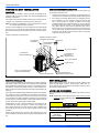
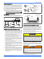
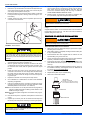
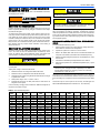
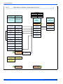
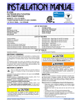
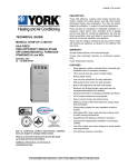
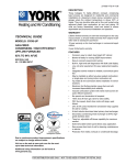
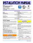
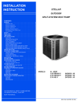
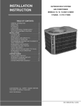
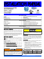
INSTALLATION MANUAL
R-22
OUTDOOR SPLIT-SYSTEM
AIR CONDITIONING
MODELS: 13 SEER
AY018-030 SERIES
1.5 TO 2.5 TONS
LISTED
ISO 9001
Certified Quality
Management System
LIST OF SECTIONS
GENERAL . . . . . . . . . . . . . . . . . . . . . . . . . . . . . . . . . . . . . . . . . . . . . . 1
SAFETY . . . . . . . . . . . . . . . . . . . . . . . . . . . . . . . . . . . . . . . . . . . . . . . . 1
UNIT INSTALLATION . . . . . . . . . . . . . . . . . . . . . . . . . . . . . . . . . . . . . 2
ORIFICE INSTALLATION . . . . . . . . . . . . . . . . . . . . . . . . . . . . . . . . . . 4
INSTALLATIONS REQUIRING AN ADD-ON TXV KIT . . . . . . . . . . . .5
EVACUATION . . . . . . . . . . . . . . . . . . . . . . . . . . . . . . . . . . . . . . . . . . .5
SYSTEM CHARGE . . . . . . . . . . . . . . . . . . . . . . . . . . . . . . . . . . . . . . .5
ELECTRICAL CONNECTIONS . . . . . . . . . . . . . . . . . . . . . . . . . . . . . .6
LIST OF FIGURES
Typical Installation . . . . . . . . . . . . . . . . . . . . . . . . . . . . . . . . . . . . . . . . 2
Oil Trap . . . . . . . . . . . . . . . . . . . . . . . . . . . . . . . . . . . . . . . . . . . . . . . . 3
Installation of Vapor Line . . . . . . . . . . . . . . . . . . . . . . . . . . . . . . . . . . . 3
Underground Installation . . . . . . . . . . . . . . . . . . . . . . . . . . . . . . . . . . . 3
Heat Protection . . . . . . . . . . . . . . . . . . . . . . . . . . . . . . . . . . . . . . . . . . 4
Orifice Installation . . . . . . . . . . . . . . . . . . . . . . . . . . . . . . . . . . . . . . . . . 4
Outdoor Unit Control Box . . . . . . . . . . . . . . . . . . . . . . . . . . . . . . . . . . .6
Typical Field Wiring (Air Handler / Electrical Heat) . . . . . . . . . . . . . . . .6
Thermostat Chart - Single Stage AC with PSC Air Handler . . . . . . . . .7
Thermostat Chart - Single Stage AC with PSC Air Handler . . . . . . . . .8
Thermostat Chart - Single Stage AC with PSC Furnace . . . . . . . . . . .9
Thermostat Chart - Single Stage AC with PSC Furnace . . . . . . . . . .10
LIST OF TABLES
Application Limitations . . . . . . . . . . . . . . . . . . . . . . . . . . . . . . . . . . . . . 1
R-22 Saturated Properties . . . . . . . . . . . . . . . . . . . . . . . . . . . . . . . . . 5
SECTION I: GENERAL
The outdoor units are designed to be connected to a matching indoor
coil with sweat connect lines. Sweat connect units are factory charged
with refrigerant for a matching indoor coil plus 15 feet of field supplied
lines.
The refrigerant charge may need to be changed for some indoor-outdoor unit combinations, elevation differences or total line lengths. Refer
to Application Data covering “General Piping Recommendations and
Refrigerant Line Length” (Part Number 036-61920-001).
SECTION II: SAFETY
This is a safety alert symbol. When you see this symbol on
labels or in manuals, be alert to the potential for personal
injury.
Understand and pay particular attention to the signal words DANGER,
WARNING, or CAUTION.
DANGER indicates an imminently hazardous situation, which, if not
avoided, will result in death or serious injury.
This product must be installed in strict compliance with the
enclosed installation instructions and any applicable local, state,
and national codes including, but not limited to building, electrical,
and mechanical codes.
INSPECTION
As soon as a unit is received, it should be inspected for possible damage during transit. If damage is evident, the extent of the damage
should be noted on the carrier’s delivery receipt. A separate request for
inspection by the carrier’s agent should be made in writing. See Local
Distributor for more information.
LIMITATIONS
The unit should be installed in accordance with all National, State and
Local Safety Codes and the limitations listed below:
1.
WARNING indicates a potentially hazardous situation, which, if not
avoided, could result in death or serious injury.
2.
CAUTION indicates a potentially hazardous situation, which, if not
avoided may result in minor or moderate injury. It is also used to
alert against unsafe practices and hazards involving only property damage.
3.
Limitations for the indoor unit, coil, and appropriate accessories
must also be observed.
The outdoor unit must not be installed with any duct work in the air
stream. The outdoor fan is the propeller type and is not designed
to operate against any additional external static pressure.
The maximum and minimum conditions for operation must be
observed to ensure a system that will give maximum performance
with minimum service.
TABLE 1: Application Limitations
Improper installation may create a condition where the operation of
the product could cause personal injury or property damage.
Improper installation, adjustment, alteration, service or maintenance can cause injury or property damage. Refer to this manual
for assistance or for additional information, consult a qualified contractor, installer or service agency.
Ambient Air Temperature
on Outdoor Coil
Min. DB
50 °F
4.
Max. DB
115 °F
Air Temperature on
Indoor Coil
Min. WB
57 °F
Max. WB
72 °F
The unit should not be operated at outdoor temperatures below
50° F without an approved low ambient operation accessory kit
installed.
347337-UIM-A-0408
347337-UIM-A-0408
SECTION III: UNIT INSTALLATION
ADD-ON REPLACEMENT/RETROFIT
LOCATION
The following steps should be performed in order to insure proper system operation and performance.
Before starting the installation, select and check the suitability of the
location for both the indoor and outdoor unit. Observe all limitations and
clearance requirements.
The outdoor unit must have sufficient clearance for air entrance to the
condenser coil, air discharge, and service access. See Figure 1.
NOTE: For multiple unit installations, units must be spaced a minimum
of 18 inches apart (coil face to coil face).
If the unit is to be installed on a hot sun exposed roof or a black-topped
ground area, the unit should be raised sufficiently above the roof or
ground to avoid taking the accumulated layer of hot air into the outdoor
unit.
1.
Change-out the indoor coil, if required, to an approved R-22 coil/
condensing unit combination with the appropriate metering device.
2.
If the outdoor unit is being replaced due to a compressor burnout,
then installation of a 100% activated alumina suction-line filter
drier in the suction-line is required, in addition to the factory
installed liquid-line drier. Operate the system for 10 hours. Monitor
the suction drier pressure drop. If the pressure drop exceeds 3
psig, replace both the suction-line and liquid-line driers. After a
total of 10 hours run time where the suction-line pressure drop has
not exceeded 3 psig, replace the liquid line drier, and remove the
suction-line drier. Never leave a suction-line drier in the system
longer than 50 hours of run time.
Provide an adequate structural support.
48” OVERHEAD
CLEARANCE
MINIMUM 24” SERVICE ACCESS
CLEARANCE ON ONE SIDE
THERMOSTAT
WEATHERPROOF
DISCONNECT
SWITCH
NEC CLASS 1 WIRING
12” CLEARANCE
AROUND PERIMETER
TO FURNACE OR
AIR HANDLER
TERMINAL BLOCK
NEC CLASS 2 WIRING
TO INDOOR COIL
NOTE:ALL OUTDOOR WIRING
MUST BE WEATHERPROOF.
CONTROL ACCESS PANEL
SEAL OPENING(S) WITH
PERMAGUM OR EQUIVALENT
FIGURE 1: Typical Installation
GROUND INSTALLATION
ROOF INSTALLATION
The unit should be installed on a solid base that is 2” above grade and
will not shift or settle, causing strain on the refrigerant lines and possible
leaks. Maintain the clearances shown in Figure 1 and install the unit in a
level position. The base pad should not come in contact with the foundation or side of the structure because sound may be transmitted to the
residence.
When installing units on a roof, the structure must be capable of supporting the total weight of the unit, including a pad, lintels, rails, etc.,
which should be used to minimize the transmission of sound or vibration into the conditioned space.
The length of the refrigerant tubing between the outdoor unit and indoor
coil should be as short as possible to avoid capacity and efficiency
losses. Excessive spacing of the outdoor unit from the home can result
in the refrigerant lines being restricted by trampling or being punctured
by lawn mowers. Locate the outdoor unit away from bedroom windows
or other rooms where sound might be objectionable.
The air conditioning unit’s copper spun filter/dryer is located on the liquid line.
Adverse effects of snow or sleet accumulating on the outdoor coil can
be eliminated by placing the outdoor unit where the prevailing wind
does not blow across the unit. Trees, shrubs, corners of buildings, and
fences standing off from the coil can reduce capacity loss due to wind
chill effect.
Provide ample clearance from shrubs to allow adequate air to pass
across the outdoor coil without leaves or branches being pulled into the
coil.
2
LIQUID LINE FILTER-DRIER
NOTE: Replacements for the liquid line drier must be exactly the same
as marked on the original factory drier. See Source 1 for O.E.M.
replacement driers.
Failure to do so or using a substitute drier or a granular type may
result in damage to the equipment.
R-22
Filter-Drier
Source 1 Part No.
Apply with Models
029-22156-000
All Models
AY
Johnson Controls Unitary Products
347337-UIM-A-0408
PIPING CONNECTIONS
Sheet Metal Hanger
The outdoor condensing unit must be connected to the indoor evaporator coil using field supplied refrigerant grade (ACR) copper tubing that is
internally clean and dry. Units should be installed only with the tubing
sizes for approved system combinations as specified in tabular data
sheet. The charge given is applicable for total tubing lengths up to 15
feet. See Application Data Part Number 036-61920-000 for installing
tubing of longer lengths and elevation differences.
Incorrect
NOTE: Using a larger than specified line size could result in oil return
problems. Using too small a line will result in loss of capacity
and other problems caused by insufficient refrigerant flow. Slope
horizontal vapor lines at least 1" every 20 feet toward the outdoor unit to facilitate proper oil return.
Correct
OIL TRAPPING
When the outdoor unit is above the indoor coil, oil trapping is necessary.
An oil trap should be provided for every 20 ft. of rise. See Figure 2.
OUTDOOR COIL
Liquid
Line
Tape
Insulated Vapor Line
FIGURE 3: Installation of Vapor Line
TO OUTDOOR UNIT
TO INDOOR COIL
Liquid Line
Insulated
Vapor Line
Cap
PVC
Conduit
10 In.
20 Ft.
FIGURE 4: Underground Installation
INDOOR
COIL
6 In.
20 Ft.
FIGURE 2: Oil Trap
PRECAUTIONS DURING LINE INSTALLATION
1.
Install the lines with as few bends as possible. Care must be taken
not to damage the couplings or kink the tubing. Use clean hard
drawn copper tubing where no appreciable amount of bending
around obstruction is necessary. If soft copper must be used, care
must be taken to avoid sharp bends which may cause a restriction.
PRECAUTIONS DURING BRAZING OF LINES
All outdoor unit and evaporator coil connections are copper-to-copper
and should be brazed with a phosphorous-copper alloy material such
as Silfos-5 or equivalent. DO NOT use soft solder. The outdoor units
have reusable service valves on both the liquid and vapor connections.
The total system refrigerant charge is retained within the outdoor unit
during shipping and installation. The reusable service valves are provided to evacuate and charge per this instruction.
Serious service problems can be avoided by taking adequate precautions to assure an internally clean and dry system.
2.
The lines should be installed so that they will not obstruct service
access to the coil, air handling system, or filter.
3.
Care must also be taken to isolate the refrigerant lines to minimize
noise transmission from the equipment to the structure.
4.
The vapor line must be insulated with a minimum of 1/2" foam rubber insulation (Armaflex or equivalent). Liquid lines that will be
exposed to direct sunlight, high temperatures, or excessive humidity must also be insulated.
5.
Tape and suspend the refrigerant lines as shown. DO NOT allow
tube metal-to-metal contact. See Figure 3.
PRECAUTIONS DURING BRAZING SERVICE VALVE
6.
Use PVC piping as a conduit for all underground installations as
shown in Figure 4. Buried lines should be kept as short as possible
to minimize the build up of liquid refrigerant in the vapor line during
long periods of shutdown
Precautions should be taken to prevent heat damage to service valve
by wrapping a wet rag around it as shown in Figure 5. Also, protect all
painted surfaces, insulation, and plastic base during brazing. After brazing, cool joint with wet rag.
7.
Pack fiberglass insulation and a sealing material such as permagum around refrigerant lines where they penetrate a wall to reduce
vibration and to retain some flexibility.
8.
For systems with total line length exceeding 50 ft., see APPLICATION DATA and worksheet "General Piping Recommendations
and Refrigerant Line Length" for vapor and liquid line sizing, calibration of liquid line pressure loss or gain, determination of vapor
line velocity, elevation limitations, orifice connections, system
charging, traps, etc.
Dry nitrogen should always be supplied through the tubing while it
is being brazed, because the temperature required is high enough
to cause oxidation of the copper unless an inert atmosphere is provided. The flow of dry nitrogen should continue until the joint has
cooled. Always use a pressure regulator and safety valve to insure
that only low pressure dry nitrogen is introduced into the tubing.
Only a small flow is necessary to displace air and prevent oxidation.
This is not a backseating valve. The service access port has a
valve core. Opening or closing valve does not close service access
port.
If the valve stem is backed out past the chamfered retaining wall,
the O-ring can be damaged causing leakage or system pressure
could force the valve stem out of the valve body possibly causing
personal injury.
Valve can be opened by removing the plunger cap and fully inserting a
hex wrench into the stem and backing out counter-clockwise until valve
stem just touches the chamfered retaining wall.
Johnson Controls Unitary Products
3
347337-UIM-A-0408
Connect the refrigerant lines using the following procedure:
1.
Remove the cap and Schrader core from both the liquid and vapor
service valve service ports at the outdoor unit. Connect low pressure nitrogen to the liquid line service port.
2.
Braze the liquid line to the liquid valve at the outdoor unit. Be sure
to wrap the valve body with a wet rag. Allow the nitrogen to continue flowing.
3.
Carefully remove the plugs from the evaporator liquid and vapor
connections at the indoor coil.
12. Release the refrigerant charge into the system. Open both the liquid and vapor valves by removing the plunger cap and with an
allen wrench back out counter-clockwise until valve stem just
touches the chamfered retaining wall. See Page 3 "PRECAUTIONS DURING BRAZING SERVICE VALVE".
13. Replace plunger cap finger tight, then tighten an additional 1/12
turn (1/2 hex flat). Cap must be replaced to prevent leaks.
Never attempt to repair any brazed connections while the system is
under pressure. Personal injury could result.
See "System Charge” section for checking and recording system
charge.
Supplied with the outdoor unit is a Schrader Valve Core and Orifice for
highest sales volume indoor coil. The valve core must be installed in
equalizer fitting of the indoor coil.
SECTION IV: ORIFICE INSTALLATION
Failure to install Schrader Valve Core on orifice applications could
result in total refrigerant loss of the system!
FIGURE 5: Heat Protection
Do not install any coil in a furnace which is to be operated during
the heating season without attaching the refrigerant lines to the coil.
The coil is under 30 to 35 psig inert gas pressure which must be
released to prevent excessive pressure build-up and possible coil
damage.
Install Schrader Valve Core as follows:
1.
Slide indoor coil out of cabinet far enough to gain access to equalizer fitting on the suction line.
2.
After holding charge is completely discharged remove black plastic cap on equalizer fitting.
3.
Install Schrader Valve Core supplied with the outdoor unit into
equalizer fitting using a valve core tool.
4.
Loosen and remove the liquid line fitting from the orifice distributor
assembly. Note that the fitting has right hand threads.
4.
Braze the liquid line to the evaporator liquid connection. Nitrogen
should be flowing through the evaporator coil.
5.
5.
Slide the grommet away from the vapor connection at the indoor
coil. Braze the vapor line to the evaporator vapor connection. After
the connection has cooled, slide the grommet back into original
position.
Install proper size orifice supplied with outdoor unit. Refer to supplied Tabular Data Sheet for specific orifice size and indoor coil
match up.
6.
After orifice is installed reinstall the liquid line to the top of the orifice distributor assembly. Hand tighten and turn an additional 1/8
turn to seal. Do not over tighten fittings.
7.
Leak test system.
6.
Protect the vapor valve with a wet rag and braze the vapor line
connection to the outdoor unit. The nitrogen flow should be exiting
the system from the vapor service port connection. After this connection has cooled, remove the nitrogen source from the liquid fitting service port.
7.
Replace the Schrader core in the liquid and vapor valves.
8.
Go to “SECTION V” or “SECTION IV” for orifice or TXV installation
depending on application.
9.
Leak test all refrigerant piping connections including the service
port flare caps to be sure they are leak tight. DO NOT OVERTIGHTEN (between 40 and 60 inch - lbs. maximum).
8.
Replace black plastic cap on equalizer fitting.
9.
Slide indoor coil back into cabinet.
LIQUID LINE
SWIVEL COUPLING
(This fitting is a right-hand thread,
turn counter-clockwise to remove)
NOTE: Line set and indoor coil can be pressurized to 250 psig with dry
nitrogen and leak tested with a bubble type leak detector. Then
release the nitrogen charge.
NOTE: Do not use the system refrigerant in the outdoor unit to purge or
leak test.
10. Evacuate the vapor line, evaporator, and liquid line to 500 microns
or less.
ORIFICE
DISTRIBUTOR
11. Replace cap on service ports. Do not remove the flare caps from
the service ports except when necessary for servicing the system.
FIGURE 6: Orifice Installation
Do not connect manifold gauges unless trouble is suspected.
Approximately 3/4 ounce of refrigerant will be lost each time a standard manifold gauge is connected.
4
Johnson Controls Unitary Products
347337-UIM-A-0408
SECTION V: INSTALLATIONS REQUIRING
AN ADD-ON TXV KIT
For installations requiring a TXV kit, refer to the Installation Instructions
accompanying the TXV kit.
Refrigerant charging should only be carried out by a qualified air
conditioning contractor.
Schrader valve core MUST NOT be installed with TXV installation.
Poor system performance or system failure could result.
Compressor damage will occur if system is improperly charged. On
new system installations, charge system per tabular data sheet for
the matched coil and follow guidelines in this instruction.
SECTION VI: EVACUATION
It will be necessary to evacuate the system to 500 microns or less. If a
leak is suspected, leak test with dry nitrogen to locate the leak. Repair
the leak and test again.
To verify that the system has no leaks, simply close the valve to the vacuum pump suction to isolate the pump and hold the system under vacuum. Watch the micron gauge for a few minutes. If the micron gauge
indicates a steady and continuous rise, it’s an indication of a leak. If the
gauge shows a rise, then levels off after a few minutes and remains
fairly constant, it’s an indication that the system is leak free but still contains moisture and may require further evacuation if the reading is
above 500 microns.
If a calibrated charging cylinder or accurate weighing device is available, add refrigerant accordingly. Otherwise, model-specific charging
charts are provided on the access panel of the unit. If mix matched TXV
indoor coils are used with these models, the following subcooling charging method must be used. Superheat charging charts are not valid with
TXV equipped systems.
SUBCOOLING CHARGING METHOD - MIXED MATCH
COILS
The recommended subcooling is 10°F
SECTION VII: SYSTEM CHARGE
1.
The factory charge in the outdoor unit includes enough charge for the
unit, a 15 ft. line set, and the smallest indoor coil match-up. Some
indoor coil matches may require additional charge. See tabular data
sheet provided in unit literature packet for charge requirements.
2.
Operate the system for a minimum of 15-20 minutes.
3.
Refer to the tabular data sheet for the recommended airflow and
verify this indoor airflow (it should be about 400 SCFM per ton).
4.
Measure the liquid refrigerant pressure P and temperature T at the
service valve.
5.
Calculate the saturated liquid temperature ST from Table 2.
6.
Subcooling temperature TC = Saturated Temperature (ST) - Liquid
Temp (T).
Do not leave the system open to the atmosphere.
The “TOTAL SYSTEM CHARGE” must be permanently stamped on the
unit data plate.
Total system charge is determined as follows:
1.
Determine outdoor unit charge from tabular data sheet.
2.
Determine indoor coil adjustment from tabular data sheet.
3.
Calculate the line charge using the tabular data sheet if line length
is greater than 15 feet.
4.
Total system charge = item 1 + item 2 + item 3.
5.
Permanently stamp the unit data plate with the total amount of
refrigerant in the system.
Set the system running in the cooling mode by setting the thermostat at least 6°F below the room temperature.
Example: The pressure P and temperature T measured at the liquid service port is 196 psig and 90°F, respectlvely. From Table 2,
the saturated temperature for 196 psig is 100°F. The subcooling
temperature TC = 100°-90°=10°F
Add charge if the calculated subcooling temperature TC in Step 6 is
lower than the recommended level. Remove and recover the refrigerant
if the subcooling TC is higher than the recommended level. See Table
2.
Check flare caps on service ports to be sure they are leak tight. DO
NOT OVERTIGHTEN (between 40 and 60 inch - lbs. maximum).
Use the following charging method whenever additional refrigerant is
required for the system charge.
TABLE 2: R-22 Saturated Properties
Pressure
PSIG
80
82
84
86
88
90
92
94
96
98
100
102
104
106
108
Temp °F
48
49
50
51
52
54
55
56
57
58
59
60
61
62
63
Pressure
PSIG
110
112
114
116
118
120
122
124
126
128
130
132
134
136
138
Temp °F
Johnson Controls Unitary Products
64
65
66
67
68
69
70
71
72
73
74
75
76
77
78
Pressure
PSIG
140
142
144
146
148
150
152
154
156
158
160
162
164
166
168
Temp °F
78
79
80
81
82
83
84
84
85
86
87
88
88
89
90
Pressure
PSIG
170
172
174
176
178
180
182
184
186
188
190
192
194
196
198
Temp °F
91
91
92
93
94
94
95
96
97
97
98
99
99
100
101
Pressure
PSIG
200
202
204
206
208
210
212
214
216
218
220
222
224
226
228
Temp °F
101
102
103
103
104
105
105
106
107
107
108
109
109
110
111
Pressure
PSIG
230
232
234
236
238
240
242
244
246
248
250
252
254
256
258
Temp °F
111
112
112
113
114
114
115
115
116
117
117
118
118
119
119
5
347337-UIM-A-0408
CONTACTOR
IT IS UNLAWFUL TO KNOWINGLY VENT, RELEASE OR DISCHARGE REFRIGERANT INTO THE OPEN AIR DURING
REPAIR, SERVICE, MAINTENANCE OR THE FINAL DISPOSAL
OF THIS UNIT.
WHEN THE SYSTEM IS FUNCTIONING PROPERLY AND THE
OWNER HAS BEEN FULLY INSTRUCTED, SECURE THE
OWNER’S APPROVAL.
GROUND
LUG
LOW
VOLTAGE
BOX
SECTION VIII: ELECTRICAL
CONNECTIONS
GENERAL INFORMATION & GROUNDING
REVERSIBLE HIGH
VOLTAGE CONDUIT PLATE
Check the electrical supply to be sure that it meets the values specified
on the unit nameplate and wiring label.
Power wiring, control (low voltage) wiring, disconnect switches and over
current protection must be supplied by the installer. Wire size should be
sized per NEC requirements.
All field wiring must USE COPPER CONDUCTORS ONLY and be
in accordance with Local, National, Fire, Safety & Electrical Codes.
This unit must be grounded with a separate ground wire in accordance with the above codes.
The complete connection diagram and schematic wiring label is located
on the inside surface of the unit service access panel.
DUAL
RUN/FAN
CAPACITOR
“FINGERED”
BUSHING
FIGURE 7: Outdoor Unit Control Box
FIELD CONNECTIONS CONTROL WIRING
1.
Route low voltage wiring into bottom of control box as shown in
Figure 6. Make low voltage wiring connections inside the low voltage box per Figures 7-9.
2.
The complete connection diagram and schematic wiring label is
located on the inside surface of the unit service access panel.
3.
Replace the corner cover removed in Step 2.
4.
All field wiring to be in accordance with national electrical codes
(NEC) and/or local-city codes.
1.
Install the proper size weatherproof disconnect switch outdoors
and within sight of the unit.
2.
Remove the screws at the top and sides of the corner cover. Slide
corner cover down and remove from unit.
NOTE: A Start Assist Kit is available and recommended for long line set
applications or in areas of known low voltage problems.
5. Mount the thermostat about 5 ft. above the floor, where it will be
exposed to normal room air circulation. Do not place it on an outside wall or where it is exposed to the radiant effect from exposed
glass or appliances, drafts from outside doors or supply air grilles.
3.
Run power wiring from the disconnect switch to the unit.
6.
4.
Route wires from disconnect through power wiring opening provided and into the unit control box as shown in Figure 6.
5.
Install the proper size time-delay fuses or circuit breaker, and
make the power supply connections.
FIELD CONNECTIONS POWER WIRING
Route the 24-volt control wiring (NEC Class 2) from the outdoor
unit to the indoor unit and thermostat.
NOTE: To eliminate erratic operation, seal the hole in the wall at the
thermostat with permagum or equivalent to prevent air drafts
affecting the operation of in the thermostat.
ALL FIELD WIRING TO BE IN ACCORDANCE WITH ELECTRIC CODE (NEC) AND/OR LOCAL CODES
POWER WIRING
208/230-1-60
24 VOLT CONTROL WIRING
MINIMUM 18 GA. WIRE
(NEC CLASS 2)
POWER WIRING
CONTROL WIRING
FACTORY WIRING
FURNACE OR AIR HANDLER TERMINAL BLOCK
C
Y
R
G
W
Y
R
G
W
* TERMINAL W IS ONLY
GND.
LUG
REQUIRED ON SYSTEMS
WITH HEAT.
CONTACTOR
TERMINALS
COIL
CONDENSING UNIT
*
ROOM THERMOSTAT
ALL OUTDOOR WIRING MUST BE WEATHERPROOF. USE COPPER CONDUCTORS ONLY.
FIGURE 8: Typical Field Wiring (Air Handler / Electrical Heat)
6
Johnson Controls Unitary Products
347337-UIM-A-0408
For additional connection diagrams for all UPG equipment refer to “Low Voltage System Wiring” document available online at www.upgnet.com in the
Product Catalog Section.
AC 1A
Single Stage Air Conditioner – PSC Air Handler
ID MODELS
AHP
SHP
MA
THERMOSTAT
SINGLE STAGE
SINGLE STAGE
AIR
AIR CONDITIONER
CONDITIONER
PSC
AIR HANDLER
*PP11C70224
PSC
1
AIR HANDLER CONTROL
SINGLE STAGE
AIR CONDITIONER
COM
24 – Volt Common
C
24 – Volt Common
Y
Full Stage Compressor
Y/Y2
Second or Full
Stage Compressor
Y
Compressor
Compressor
Contactor
RH
24 – Volt Hot
(Heat XFMR)
R
24 – Volt Hot
G
Fan
G
Fan
W2
Second Stage Heat
RC
24 – Volt Hot
(Cool XFMR)
Y1
Single Stage Compressor
O
Reversing Valve
Energized in Cool
X/L
Malfunction Light
W
Full Stage Heat
HM1
Humidistat
W1
First Stage Heat
24VAC Humidifier
(Optional)
24VAC
Electronic Air Cleaner
(Optional)
Clipping Jumper W914 for
electric heat on thermostat
is not necessary
HUM
Humidity Switch
Open on Humidity Rise
HUM OUT
(24 VAC out)
Humidifier
EAC(24 VAC out)
Electronic Air Cleaner
Move HUM STAT
jumper to “YES”
if humidistat is to be used.
Refer to AH documentation
for W1 and W2 electric
heat staging options.
Other
PartPart
Numbers:
Numbers:
SAP = Legacy
265902
159480 = 031-09167
031-09156
2
1
FIGURE 9: Thermostat Chart - Single Stage AC with PSC Air Handler
Johnson Controls Unitary Products
7
347337-UIM-A-0408
AC 1B
Single Stage Air Conditioner – PSC Air Handler
ID MODELS
AHP
SHP
THERMOSTAT
THERMOSTAT
*BN11C00124
*BP11C50124
*BN11C01124
*DP11C40124
*DN11C00124
MA
SINGLE STAGE
AIR
CONDITIONER
PSC
AIR HANDLER
PSC
1
AIR HANDLER CONTROL
SINGLE STAGE
AIR CONDITIONER
C
24 – Volt Common
C
24 – Volt Common
COM
24 – Volt Common
C
24 – Volt Common
Y
Full Stage Compressor
Y
Full Stage Compressor
Y/Y2
Second or Full
Stage Compressor
Y
Compressor Contactor
RH
24 – Volt Hot
(Heat XFMR)
RH
24 – Volt Hot
(Heat XFMR)
R
24 – Volt Hot
G
Fan
G
Fan
G
Fan
W2
Second Stage Heat
RC
24 – Volt Hot
(Cool XFMR)
RC
24 – Volt Hot
(Cool XFMR)
Y1
Single Stage Compressor
O
Reversing Valve
Energized in Cool
X/L
Malfunction Light
W
Full Stage Heat
W
Full Stage Heat
2
External Humidistat
(Optional)
Open on Humidity Rise
Thermostat Installer Setup Selection of GAS/ELEC
1-System Type-must be
switch on thermostat
set to 0
is not necessary
Thermostat Installer Setup
15-Compressor Protection
must be set to 5
2
W1
First Stage Heat
24VAC Humidifier
(Optional)
24VAC
Electronic Air Cleaner
(Optional)
Part Number:
S1-2HU16700124
HUM
Humidity Switch
Open on Humidity Rise
HUM OUT
(24 VAC out)
Humidifier
EAC(24 VAC out)
Electronic Air Cleaner
Move HUM STAT
jumper to “YES”
if humidistat is to be used.
Refer to AH documentation
for W1 and W2 electric
heat staging options.
Other
PartPart
Numbers:
Numbers:
SAP = Legacy
265902
159480 = 031-09167
031-09156
2
1
FIGURE 10: Thermostat Chart - Single Stage AC with PSC Air Handler
8
Johnson Controls Unitary Products
347337-UIM-A-0408
AC 5D
Single Stage Air Conditioner – Single Stage PSC Furnace
ID MODELS
G*(8/9)S
THERMOSTAT
GF(8/9)
G*9F
LF8
L(Y/M)8S
TG(8/9)S
G8C
(G/T)GLS
SINGLE STAGE
PSC
FURNACE
*PP11C70224
SINGLE STAGE PSC
FURNACE
SINGLE STAGE
AIR
CONDITIONER
1
SINGLE
STAGE
SINGLE
STAGE
AIR
CONDITIONER
AIR
CONDITIONER
C
24 – Volt Common
C
24 – Volt Common
Y
Full Stage Compressor
Y/Y2
Full Stage Compressor
YY
Compressor
Compressor
Contactor
RH
24 – Volt Hot
(Heat XFMR)
R
24 – Volt Hot
G
Fan
G
Fan
W
Full Stage Heat
RC
24 – Volt Hot
(Cool XFMR)
W
Full Stage Heat
HM1
Humidistat
24VAC Humidifier
(Optional)
Clipping Jumper W914 for
electric heat on thermostat
is not necessary
Other Part Numbers:
SAP = Legacy
265901 = 031-09166
1
FIGURE 11: Thermostat Chart - Single Stage AC with PSC Furnace
Johnson Controls Unitary Products
9
347337-UIM-A-0408
AC 5E
Single Stage Air Conditioner – Single Stage PSC Furnace
ID MODELS
G*(8/9)S
THERMOSTAT
THERMOSTAT
*BN11C00124
*BP11C50124
*BN11C01124
*DP11C40124
*DN11C00124
GF(8/9)
G*9F
LF8
L(Y/M)8S
G8C
TG(8/9)S
(G/T)GLS
SINGLE STAGE
PSC
FURNACE
SINGLE STAGE PSC
FURNACE
SINGLE STAGE
AIR
CONDITIONER
1
SINGLE STAGE
AIR CONDITIONER
C
24 – Volt Common
C
24 – Volt Common
C
24 – Volt Common
C
24 – Volt Common
Y
Full Stage Compressor
Y
Full Stage Compressor
Y/Y2
Full Stage Compressor
Y
Compressor Contactor
RH
24 – Volt Hot
(Heat XFMR)
RH
24 – Volt Hot
(Heat XFMR)
R
24 – Volt Hot
G
Fan
G
Fan
G
Fan
W
Full Stage Heat
RC
24 – Volt Hot
(Cool XFMR)
RC
24 – Volt Hot
(Cool XFMR)
W
Full Stage Heat
W
Full Stage Heat
2
External Humidistat
(Optional)
Open on Humidity Rise
24VAC Humidifier
(Optional)
Thermostat Installer Setup Selection of GAS/ELEC
1-System Type-must be
switch on thermostat
set to 0
is not necessary
Thermostat Installer Setup
15-Compressor Protection
must be set to 5
2
Part Number:
S1-2HU16700124
Other Part Numbers:
SAP = Legacy
265901 = 031-09166
1
FIGURE 12: Thermostat Chart - Single Stage AC with PSC Furnace
10
Johnson Controls Unitary Products
347337-UIM-A-0408
INDICATIONS OF PROPER OPERATION
Maintenance
Cooling
1.
Dirt should not be allowed to accumulate on the outdoor coils or
other parts in the air circuit. Clean as often as necessary to keep
the unit clean. Use a brush, vacuum cleaner attachment, or other
suitable means.
2.
The outdoor fan motor is permanently lubricated and does not
require periodic oiling.
3.
If the coil needs to be cleaned, it should be washed with Calgon
Coilclean (mix one part Coilclean to seven parts water). Allow
solution to remain on coil for 30 minutes before rinsing with clean
water. Solution should not be permitted to come in contact with
painted surfaces.
4.
Refer to the furnace or air handler instructions for filter and blower
motor maintenance.
5.
The indoor coil drain pan should be inspected and cleaned regularly to prevent odors and assure proper drainage.
1.
The outdoor fan should be running, with warm air being discharged from the top of the unit.
2.
The indoor blower (furnace or air handler) will be operating, discharging cool air from the ducts. Coils or other parts in the air circuit should be cleaned as often as necessary to keep the unit
clean. Use a brush, vacuum cleaner attachment, or other suitable
means.
3.
The vapor line at the outdoor unit will feel cool to the touch.
4.
The liquid line at the outdoor unit will feel warm to the touch.
Instructing the Owner
Assist owner with processing warranty cards. Review Owners Guide
and provide a copy to the owner and guidance on proper operation and
maintenance. Instruct the owner or the operator how to start, stop and
adjust temperature setting.
When applicable, instruct the owner that the compressor is equipped
with a crankcase heater to prevent the migration of refrigerant to the
compressor during the “OFF” cycle. The heater is energized only when
the unit is not running. If the main switch is disconnected for long periods, do not attempt to start the unit until 8 hours after the switch has
been connected. This will allow sufficient time for all liquid refrigerant to
be driven out of the compressor.
The installer should also instruct the owner on proper operation and
maintenance of all other system components.
Johnson Controls Unitary Products
11
NOTES
Subject to change without notice. Printed in U.S.A.
Copyright © 2008 by Johnson Controls, Inc. All rights reserved.
Johnson Controls Unitary Products
5005 York Drive
Norman, OK 7306
347337-UIM-A-0408
Supersedes: 259715-UIM-A-0606