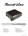
1
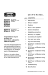
®
How to Install and Operate
the XA2150 Amplifier
Contents
®
L
VE
LE
PO
W
ER
AX
M
HIG
H
IN
PU
F
M
SSST
BA
OO
-B
IN
LP
F
0
OF
T
25
ON
50
LO
W
F
HP
0
25
ER
50
OV
X-
F
HP
L
F
LP
LL
FU
R
PA
S
SO
UT
PU
T
L
R
PR
OT
EC
T
Welcome!
What you're holding in your hands is no ordinary
owner's manual. We've tried to make the instructions
in this book clear and easy to follow.
For your Jensen amplifier to work right, it must be
installed correctly. This manual will show you how to
install your new amplifier like a pro. It's a good idea to
read all of these instructions before you begin the
installation. Most installations are straightforward and
can be handled by a do-it-yourselfer with the right
tools, patience, and the ability to follow instructions.
But, do-it-yourself installation isn't for everyone. If you
still don't feel confident after reading this book,
consider turning the installation job over to someone
better suited to it.
Warranty Service
If your Jensen amplifier should ever require service,
you will need to have the original dated receipt. If you
ever need to return the unit for any reason, always
include the receipt with the product.
Technical Assistance
Features ........................................ 2
Installation ................................... 2
Before You Begin
Installation ..................................... 2
Amplifier Location .......................... 2
Disconnect Battery ........................ 2
• Amplifier Installation Kit ............. 2
Supplies and Tools
Needed .......................................... 3
Routing Wires ................................ 3
• Bigger is Better .......................... 3
Wiring ............................................. 4
Power and Outputs ........................ 4
Power Terminal (BATT +12V) ........ 4
Ground Terminal (GND) ................. 4
Remote Terminal (RMT +12V) ....... 4
Fuses ............................................. 4
Inputs and Controls ....................... 5
Input Wiring.................................... 5
Pass Output ................................... 5
Power Light .................................... 5
Protect Light .................................. 5
Input Level Control ........................ 6
Bass Boost..................................... 6
Crossover ...................................... 6
Speaker Wiring .............................. 7
Testing .......................................... 9
Reconnect Battery ......................... 9
Test Power Wiring .......................... 9
Test Speaker Connections ............ 9
• Dealing with Alternator
Noise .......................................... 9
• Installing in Trunk ..................... 10
• Crimp Connections .................. 10
• Securing Wires ........................ 10
• Speaker and
Power Wires ............................ 10
Troubleshooting ....................... 11
Specifications
and Warranty ............................. 12
For technical assistance with the operation or installation
of the XA2150, call 1-800-323-0221.
5311Eamp.p65
1
4/10/99, 8:13 PM
®
XA2150
Features
The Jensen XA2150 power amplifier is a twochannel 300-watt total system power automotive
amplifier. The XA2150 includes:
• RCA inputs
• High level inputs
• Continuously variable low pass or high
pass crossover
• Bass boost feature
• Remote turn on/off
• Electronic protection circuitry to protect the
amplifier from short circuit, DC offset and
thermal overload
• Unique, super-efficient heat sink design
• 2 x 75 watts RMS per channel (2 x 150
watts peak)
• Pass through connectors for adding other
amps
• 150 watts RMS bridged into a 4 ohm load
• Bridgeable design to direct full power to one
speaker
Audio Amplifiers
Amplification offers two advantages:
• The XA2150 amplifier can make the sound
of your receiver fuller and richer, even at low
volume levels.
• Many automotive receivers provide four to
10 watts at maximum power. At 75 watts
RMS per channel (200 watts bridged), the
XA2150 can be played substantially louder,
permitting the use of more powerful
speakers.
Installation
Before You Begin Installation
Before you begin, you will need tools, supplies
and adapters. It is best to make sure you have
everything you need before you start. There is a
list of supplies and tools on the next page.
Disconnect Battery
Before you begin, always
disconnect the battery
negative terminal.
–
+
Amplifier Location
Important
Allow air circulation around the amplifier.
The XA2150 amplifier’s compact design
allows greater flexibility in mounting. It can be
mounted under a seat or in the trunk.
When selecting a location, remember that
amplifiers generate heat. Select a location
where air can circulate around the amplifier.
Do not cover the XA2150 with carpets or
enclose it behind interior trim panels. Do not
mount the amplifier in an inverted or upside
down configuration. Every installation will be
a bit different based upon vehicle design.
Check all locations and placements carefully
before making any cuts or connections.
Important
If wiring connections are made wrong, the unit
will not operate properly and it could be
damaged. Follow the installation instructions
carefully, or have the installation handled by
an experienced technician.
Professional Tip
Amplifier Installation Kit
Your installation job will be much easier if you
purchase an amplifier installation kit. These
kits often include low-level RCA cables, extra
large power and ground wires, a fuse or circuit
breaker and connector for the battery.
2
5311Eamp.p65
2
4/10/99, 8:13 PM
®
XA2150
Supplies and Tools Needed
Routing Wires
Supplies:
• Speaker wire (12 gauge for subwoofers, 16-18
gauge for other speakers)
• Sheet metal type screws for mounting amplifier
• Electrical tape
• Solderless crimp connectors
• 1/2" thick plywood or particle board to mount
amplifier on
Battery
Battery
Connector
Fuse or
Circuit
Breaker
Tools:
•
•
•
•
•
Flat and Phillips screwdrivers
Wire cutters
Wire strippers
Cordless or standard electric drill and drill bit set
Crimping tool (if using solderless crimp connectors)
• 12-volt test light or digital multimeter
• Wire brush or scraper (to remove paint for a
good ground connection to vehicle)
• Soldering iron and rosin core solder (if you're
going to solder your connections)
Amplifier Installation Kit:
You will need an amplifier installation kit to install
your amp properly because it contains all the
wire and connectors that you will need to hook
up your new amp right the first time. If you want
to purchase these items separately you will need
the following:
• 20-25 feet of 8 gauge wire
• 30 amp fuse or circuit breaker (to be hooked up
at the battery)
• 20 feet of 18 gauge wire for the remote turn-on/
power antenna lead
• RCA cable (for signal input from radio)
– 20 feet for trunk installation
– 12 feet for under-seat installation
• Two 8 gauge ring terminals (one for the battery
connection and the other for the ground connection at the amp). You may need two additional
ring terminals if you are using a circuit breaker at
the battery.
• Two 8 gauge barrel connectors (you may need
these depending on what type of fuse holder you
have)
• Two 8 gauge spade terminals (to hook up power
at the amp)
• Four 12 gauge spade terminals for subwoofers or
16-18 gauge spade terminals for other speaker
connections to amp
• One 18 gauge spade terminal for remote turn-on/
power antenna lead
Grommet
To prevent
damage to
power wire
Receiver
Power Wire
(8 gauge
wire or
larger)
Power Antenna
Turn-on Wire
(18 gauge wire)
RCA Cables
Speakers
Amplifier
Ground Screw
Drill 1/8" hole in
chassis sheet metal
Use the same ground if
using multiple amplifiers
Professional Tip
Bigger is better
Stereo installation dealers sell extra thick
power and speaker wires to ensure best
sound. Look for 8 gauge power wire, especially if you have several amplifiers.
3
5311Eamp.p65
3
4/10/99, 8:14 PM
®
XA2150
Wiring
Power and Outputs
+ 12V
FUSE
RMT
GND
L+
L–
R–
R+
30A
POWER
Remote Terminal (RMT +12V)
Power Terminal (BATT +12V)
Connect directly to the vehicle battery+
terminal with 8 gauge wire (minimum).
+ 12V
RMT
SPEAKER
GND
Connect the radio power antenna lead from
the receiver to the amplifier REMOTE terminal.
This turns the amplifier on whenever the receiver is turned on. If a power antenna lead is
not available, connect this wire to the radio or
accessory fuse.
+ 12V
Battery
Terminal
Adapter
Install as close
to the battery
as possible
RMT
GND
Spade
Connector
Not Supplied
30 amp Fuse
or Circuit Breaker
8 Gauge
Wire
To Battery+
Terminal
Spade
Connector
Butt
Connector
(not supplied)
To Receiver
Power
Antenna Lead
8 Gauge
Wire
Ground Terminal (GND)
Connect to a good chassis ground. The ground
connection should be to clean, unpainted metal
to provide a good electrical connection.
+ 12V
RMT
Fuses
FUSE
Use only one 30 amp
blade-type fuse.
GND
30A
Ring
Connector
Sheet Metal
Screw
(supplied)
Spade
Connector
8 Gauge
Wire
Drill 1/8" hole
in chassis
sheet metal
4
5311Eamp.p65
4
4/10/99, 8:14 PM
®
XA2150
Inputs and Controls
HIGH INPUT
PASS OUTPUT
LOW INPUT
POWER
PROTECT
L
L
R
Input Wiring
R
Pass Output
Inputs may be high level (from the receiver's
speaker) or low level (from special low level
outputs). Low level input is preferred for best
performance.
PASS OUTPUT
L
Important
Use only the low level or high level input, do
not use both at one time.
R
Power Light
Low Level Input
Use a pair of shielded stereo audio cables with
RCA type jacks. Most trunk-mount amplifier
installations require 20-foot RCA cables. Most
under-seat and pickup truck installations use
12-foot cables.
Connect RCA cables from your receiver to the
RCA input jacks on the amplifier.
High Level Input
POWER
The power light comes on when 12
volt power is available at both the
battery +12 volt and RMT wires.
Protect Light
PROTECT
Connect left and right speaker wires coming
from radio to high level input plug as shown.
Use pass through (PASS
OUTPUT) connectors for
adding other amplifiers.
The red protect light comes on
when the amplifier shuts down from
overheating or a short circuit
(speaker failure).
White-Left (+)
White/Black-Left (–)
Gray-Right (+)
Gray/Black-Right (–)
Black (ground)
Radio
L R
L R
+– – +
Splice (as
necessary)
or
HIGH INPUT
LOW INPUT
POWER
L
R
Hi level
input plug
on amp
5
5311Eamp.p65
5
4/10/99, 8:14 PM
®
XA2150
LEVEL
BASSBOOST
Crossover (X-OVER)
Adjust the crossover to accommodate your
chosen installation method.
OFF ON
MIN
MAX
LPF
50
250
HPF
X-OVER
LPF HPF
FULL
• LPF –(low pass filter) only bass
tones go to speakers. Use with
woofers or subwoofer.
X-OVER
• FULL –all tones go to speakers. Use with full-range speakers.
LPF HPF
FULL
• HPF –(high pass filter) blocks
very low tones from the speakers. Use with 6" or smaller
speakers.
LPF
50
250
Input Level Control
The input level control matches the
output of your radio to the input of
the amplifier. After the installation
is complete, make sure the input
MIN MAX
level control on the amp is turned
down all the way (counterclockwise or all the
way to the left). Play a tape or CD (make sure
bass and treble settings or EQ are flat too)
and turn the volume up slowly until you just
start to hear distortion. Now back the volume
down just a bit. On the amp, slowly turn up
the input level control (clockwise or to the
right) until you just start to hear distortion and
back it down a bit. Now your radio and amplifier levels are matched.
LEVEL
Use LPF and HPF to adjust from
50 to 250Hz.
When using your Jensen amplifier
50
250
to run a subwoofer and two fullHPF
range speakers (known as Trimode or three channel operation)
you will need to purchase separate
50
250
high and low pass crossovers from
your local retailer. A pair of high
pass crossovers for your full range speakers
and a low pass filter for the subwoofer. This
will allow the amplifier to work properly when
installing it in Tri-mode. Failure to install
these filters may damage your amplifier and/
or your speakers.
Bass Boost
BASSBOOST
BASS BOOST increases the
volume of bass by up to 6 dB
at 45Hz.
OFF ON
6
5311Eamp.p65
6
4/10/99, 8:14 PM
®
XA2150
Speaker Wiring
2 Speakers
2 Subwoofers
RCA Cables
RCA Cables
2/4Ω
2/4Ω
2/4Ω
L+
L–
R–
R+
L+
2/4Ω
L–
R–
R+
X-OVER
X-OVER
LPF HPF
FULL
LPF HPF
FULL
7
5311Eamp.p65
7
4/10/99, 8:14 PM
®
XA2150
2 Speakers + Subwoofer
Bridged Subwoofer
RCA Cables
RCA Cables
2/4Ω
2/4Ω
4Ω
4Ω
L+
L–
R–
L+
R+
L–
R–
R+
High Pass
Filters
X-OVER
4Ω
minimum
LPF HPF
FULL
Low Pass
Filter
(available at
most car stereo
installation
stores)
X-OVER
LPF HPF
FULL
Important
When running a subwoofer and two full-range
speakers together (Tri-mode operation), high
and low pass filters must be used. Failure to
install these filters will damage your amp and/
or speakers.
8
5311Eamp.p65
8
4/10/99, 8:14 PM
®
XA2150
✓ Testing
Before you finish the installation, you should do the following tests to make sure the wiring is correct
and everything is operating properly.
Reconnect Battery
When wiring is complete,
reconnect the battery
negative terminal.
Professional Tip
Dealing with Alternator Noise
–
+
Test Power Wiring
1. Turn on the receiver but do not turn up
the volume. The amplifier power light
should come on. If not, check the
RMT and +12V wires.
2. Turn up the receiver volume slightly. All
speakers should operate. If not, check
wiring connections at amplifier and
speakers.
The vehicle alternator can cause a “siren”
sound in the speakers that changes with
engine speed. To prevent alternator noise:
• Do not bundle RCA cables with speaker
or power wires
• Do not run speaker wires parallel to
power wires
• If you have more than one amplifier,
connect all ground wires to the same
screw
• Make sure all wires are as short as
possible
• Make sure the receiver black wire has a
good connection to the vehicle chassis
ground
Test Speaker Connections
These tests make sure the speakers are
connected right. If speakers don’t play at all,
one (or both) speaker wires may be disconnected. If the wrong speaker plays (you hear
left speaker when you expect right speaker)
make sure you connected the wires correctly.
Once everything is operating correctly,
reassemble vehicle trim and dashboard.
9
5311Eamp.p65
9
4/10/99, 8:14 PM
®
XA2150
Professional Tip
Professional Tip
Installing in Trunk
Securing Wires
When installing the amplifier in the trunk, run
the power wires along the same path as the
other vehicle wiring. Many cars have insulated
channels for wiring. You will have to remove
the door sill trim and the carpet.
Be proud of your installation! Use wire ties to
bundle wires together when possible. (But
never bundle speaker wires and power wires
together!)
Professional Tip
Crimp Connections
Purchase crimp connectors and crimping
tool. Connectors are color coded.
1. Strip 1/4 inch (6mm) of insulation from
both wires.
2. Insert into connector.
3. Crimp tightly.
You can make permanent splices (using butt
connectors) or select connectors that can be
removed and reinstalled.
1
2
3
Secure loose wires to the vehicle to make
sure they don’t rub or rattle.
Professional Tip
Speaker and Power Wires
Do not run speaker and power wires next to
each other. Power wires can generate a
“siren” sound in the speakers. Run speaker
and power wires on opposite sides of the car.
Strip wire
1/4" (6mm)
10
5311Eamp.p65
10
4/10/99, 8:14 PM
®
XA2150
Troubleshooting
Problem
Possible Cause
Corrective Action
Amplifier does not operate
(power LED not on) when
vehicle and radio are on
No power to +12V terminal
Repair wire or connections
No power to remote wire with radio on
Check connections to radio with test light
Fuse blown
Check fuse
Radio volume needs to be
turned up too high for amp
to work
Input level control (gain control)
adjusted too low
Adjust input level control (gain control)
Radio volume is too sensitive
Input level control adjusted too high
Adjust input level control to lower setting
Sound from only one speaker
Defective speaker
Replace speaker
Poor connections to speaker (wire)
Check connections
Speaker wires shorting together
Separate speaker wires and insulate
RCA input cable defective
Replace cable
Sound distorted
Input level control adjusted too high
Adjust input level control
Blows fuses
Speaker wires shorting together
Separate speaker wires and insulate
Power wires hooked up incorrectly
Check power wire connections
Speakers blown or defective
Check speakers
Radio has poor noise immunity
Disconnect audio inputs to amplifier – if noise disappears
then the radio is at fault
Improper ground connections
Make sure radio and amplifier are grounded to the same point
Loud pop in speakers when
power is turned on or off
Remote wire (blue) not properly
connected
Refer to page 4 for proper installation. If radio does not have a
power antenna lead and you have connected the remote lead to
an ignition source then you may get a “pop” in your speakers.
This is not uncommon. You may have to put a switch in line with
the remote lead to turn the amp on/off manually.
Protect light comes on/
amplifier shuts down
Amp is in thermal protection
Let amp cool down before attempting to turn back on (some
installations may require a fan to keep the amp cool, especially if
you are driving subwoofers with the amp)
Faulty speaker connection and/or
crossover
Check speakers and/or crossovers for loose or bad connections
Low battery voltage
Make sure you are getting between 10.8-15.6 volts to the
amplifier with a digital multimeter measured at the amplifier
Speaker impedance less than 2 ohms
per channel
If you are using 4 ohm speakers you cannot have more than two
speakers wired in parallel per channel Amp will not operate
into 2 ohms bridged
Speaker wires not connected to
speakers properly
Refer to pages 5, 6 and 7 for proper installation
Alternator whine in outputs
(vehicle ignition noise)
No output on channels
Input hooked up incorrectly
Can’t find cause of problem
Contact Jensen Technical Assistance (1-800-323-0221)
11
5311Eamp.p65
11
4/10/99, 8:14 PM
Specifications
XA2150 Amplifier
Power output @ 14.4 VDC, 20-20 kHz ............ (4 ohms) 75 Watts per channel RMS, < 00.08% THD
(2 ohms) 100 Watts per channel RMS, < 00.1% THD
(4 ohms) bridged 200 Watts per channel RMS, < 00.1% THD
Frequency Response .......................................................................................... 20 Hz-20 kHz ± 3 dB
Signal to Noise Ratio @ Rated Power .................................................................................... >100 dB
Channel Separation @ Ref. Power ............................................................................... >65 dB, 1 kHz
THD & IMD @ Ref. Power into 2 ohms ..................................................................................... <0.1%
Speaker Impedance .............................................................................................................. 2-8 ohms
Input Impedance ............................................................................................................... 20 k ohms
Crossover Frequencies ...................................................................................... Low/High: 50-250 Hz
Power Requirement .................................................................. 14.4 VDC (10.8-15.6 VDC allowable)
Fuse Requirements ........................................................................................ 30 amp blade-type fuse
Dimensions ........................................................... 2.25" x 11.125" x 8" (56.5mm x 282mm x 203mm)
Specifications subject to change without notice.
Limited One Year Warranty–USA and Canada
Length of Warranty. This warranty from Recoton Mobile
Electronics shall be in effect for a period of one year from
the date of the first consumer purchase.
If shipment of the product is required, it should be packed
securely. The original dated bill of sale must always be
included with the product as proof of warranty coverage.
Persons Protected. This warranty will be enforceable by
the original owner and any subsequent owners during the
warranty period so long as proof of date of purchase from
an authorized Jensen dealer is presented whenever
warranty service is required.
What We Will Pay For. We will pay for all labor and
material expenses required to repair the product, but you
must pay any labor costs for the removal and/or installation
of the product. If the product is shipped for warranty
service, you must prepay the initial shipping charges, but
Jensen will pay the return shipping charges if the product is
returned to an address inside the USA or Canada.
What is Covered. Except as otherwise specified below,
this warranty covers all defects in material and workmanship in this product. The following are not covered: damage
resulting from accident, misuse, abuse, neglect, product
modification, improper installation, incorrect line voltage,
unauthorized repair or failure to follow instructions supplied
with the product; damage occurring during shipment (claims
must be presented to the carrier); elimination of car static
or other electrical interferences; any product purchased
outside USA or Canada, or on which the serial number
has been defaced, modified or removed.
How You Can Get Service.
U.S. Purchasers. Please telephone Jensen at
1-800-323-4815. We will either inform you of the name
and address of an authorized Jensen repair station which
will service the product or will advise you to send the
product to a factory service center.
Canadian Purchasers. The product should be returned
to the Jensen dealer from whom it was purchased and
such dealer either will service or arrange for service of
the product.
Limitation of Implied or Statutory Warranties and
Conditions. All implied or statutory warranties and
conditions, including warranties or conditions of merchantability, fitness for particular purposes and non-infringement,
are limited in duration to the length of this warranty.
Exclusion of Certain Damages. Jensen’s liability is
limited to the repair or replacement, at our option, of any
defective product and shall not include incidental or
consequential economic damages of any kind.
Some states and/or provinces do not allow limitations on
how long an implied warranty lasts and/or do not allow the
exclusion or limitation of incidental or consequential
damages, so the above limitations and exclusions may not
apply to you.
This warranty gives you specific legal rights, and you may
also have other rights which vary from state to state and
province to province.
®
Recoton Mobile Electronics
A Division of Recoton Audio Corporation
A RECOTON® COMPANY
1090 Emma Oaks Trail
Lake Mary, Florida 32746
©1998 Recoton Audio Corporation
5311Eamp.p65
12
4/10/99, 8:14 PM