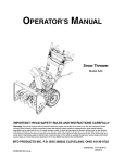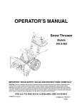
1
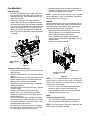
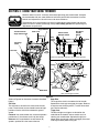
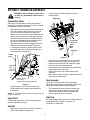
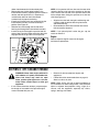
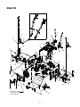
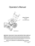
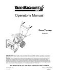
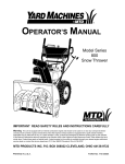
Operator’s Manual
9
Han
d
Op
era
tion
Sin
gle
Ele
ctri
cS
tart
Tw
o
HP
Power Steer Drive
28” Snow Thrower
Model
31AH553G401
Sta
ge
12"
Imp
elle
r
IMPORTANT: Read safety rules and instructions carefully before operating equipment.
Warning: This unit is equipped with an internal combustion engine and should not be used on or near any unimproved forestcovered, brush-covered or grass-covered land unless the engine’s exhaust system is equipped with a spark arrester meeting
applicable local or state laws (if any). If a spark arrester is used, it should be maintained in effective working order by the operator.
In the State of California the above is required by law (Section 4442 of the California Public Resources Code). Other states may have
similar laws. Federal laws apply on federal lands. A spark arrester for the muffler is available through your nearest engine authorized
service dealer or contact the service department, P.O. Box 368022 Cleveland, Ohio 44136-9722.
MTD PRODUCTS INC. P.O. BOX 368022 CLEVELAND, OHIO 44136-9722
PRINTED IN U.S.A.
FORM NO. 770-10028A
(7/99)
TABLE OF CONTENTS
Content
Page
Important Safe Operation Practices................................................................... 3
Assembling Your Snow Thrower ....................................................................... 5
Know Your Snow Thrower ................................................................................. 7
Operating Your Snow Thrower........................................................................... 9
Making Adjustments .......................................................................................... 11
Maintaining Your Snow Thrower ........................................................................ 12
Servicing Your Snow Thrower............................................................................ 15
Off-Season Storage ........................................................................................... 18
TroubleshootingGuide ....................................................................................... 19
Parts List............................................................................................................ 20
FINDING MODEL NUMBER
This Operator’s Manual is an important part of your new snow thrower. It will help you assemble, prepare
and maintain the unit for best performance. Please read and understand what it says.
Before you start assembling your new equipment, please locate the model plate on the
equipment and copy the information from it in the space provided below. The information on
the model plate is very important if you need help from our Customer Support Department or
an authorized dealer.
•
You can locate the model number by looking at the lower frame cover on the rear of your snow
thrower. See page 27. A sample model plate is also explained below. For future reference, please
copy the model number and the serial number of the equipment in the space below.
(Model Number)
(Serial Number)
Copy the model number here:
Copy the serial number here:
MTD PRODUCTS INC
CLEVELAND, OHIO 44136
CALLING CUSTOMER SUPPORT
If you have difficulty assembling this product or have any questions regarding the controls, operation or
maintenance of this unit, please call the Customer Support Department.
Call 1- (330) 220-4MTD (4683) or 1- (800)-800-7310 to reach a Customer Support
representative. Please have your unit’s model number and serial number ready when you
call. See previous section to locate this information. You will be asked to enter the serial
number in order to process your call.
2
SECTION 1: IMPORTANT SAFE OPERATION PRACTICES
This Warning symbol points out important safety instructions which, if not followed, could endanger the
personal safety and/or property of yourself and others. Read and follow all instructions in this manual
before attempting to operate your snow thrower. Failure to comply with these instructions may result in
personal injury. When you see this symbol, heed its warning.
DANGER: Your snow thrower was built to be operated according to the rules for safe operation in
this manual. As with any type of power equipment, carelessness or error on the part of the operator can
result in serious injury. This equipment is capable of amputating hands and feet and throwing objects.
Failure to observe the following safety instructions could result in serious injury or death.
WARNING:
The Engine Exhaust from this product contains chemicals known to the State of
California to cause cancer, birth defects or other reproductive harm.
Training
•
•
•
•
•
Read this operators manual carefully in its entirety
before attempting to assemble or operate this
machine. Be completely familiar with the controls
and the proper use of this machine before operating
it. Keep this manual in a safe place for future and
regular reference and for ordering replacement
parts.
Never allow children under 14 years old to operate
a snow thrower. Children 14 years old and over
should only operate snow thrower under close
parental supervision. Only persons well acquainted
with these rules of safe operation should be allowed
to use your snow thrower.
No one should operate this unit while intoxicated or
while taking medication that impairs the senses or
reactions.
Keep the area of operation clear of all persons,
especially small children and pets.
Exercise caution to avoid slipping or falling,
especially when operating in reverse.
•
•
•
•
•
Operation
•
•
Preparation
•
•
•
•
off any spilled gasoline before starting the engine as
it may cause a fire or explosion.
Use a grounded three wire plug-in for all units with
electric drive motors or electric starting motors.
Adjust collector housing height to clear gravel or
crushed rock surface.
Never attempt to make any adjustments while
engine is running (except where specifically
recommended by manufacturer).
Let engine and machine adjust to outdoor
temperature before starting to clear snow.
Always wear safety glasses or eye shields during
operation or while performing an adjustment or
repair, to protect eyes from foreign objects that may
be thrown from the machine in any direction.
Thoroughly inspect the area where the equipment is
to be used and remove all door mats, sleds, boards,
wires and other foreign objects.
Disengage all clutches and shift into neutral before
starting engine.
Do not operate equipment without wearing
adequate winter outer garments. Do not wear
jewelry, long scarfs or other loose clothing which
could become entangled in moving parts. Wear
footwear which will improve footing on slippery
surfaces.
Before working with gasoline, extinguish all
cigarettes and other sources of ignition. Check the
fuel before starting the engine. Gasoline is an
extremely flammable fuel. Do not fill the gasoline
tank indoors, while the engine is running, or until
engine has been allowed to cool at least two
minutes. Replace gasoline cap securely and wipe
•
•
•
3
Do not put hands or feet near or under rotating
parts. Keep clear of discharge opening and auger at
all times.
Exercise extreme caution when operating on or
crossing gravel drives, walks, or roads. Stay alert
for hidden hazards or traffic. Do not carry
passengers.
After striking a foreign object, stop the engine,
remove wire from spark plug, and thoroughly
inspect the snow thrower for any damage. Repair
the damage before restarting and operating the
snow thrower.
If the snow thrower should start to vibrate
abnormally, stop the engine and check immediately
for the cause. Vibration is generally a warning of
trouble.
Stop engine whenever you leave the operating
position, before unclogging the collector/impeller
housing or discharge guide, and making any
repairs, adjustments, or inspections. Never place
your hand in the discharge openings. Use a stick or
wooden broom handle to unclog the discharge
opening.
•
•
•
•
•
•
•
•
•
•
Take all possible precautions when leaving the unit
unattended. Disengage the collector/impeller, shift
into neutral, stop the engine, and remove the key.
When cleaning, repairing, or inspecting, make
certain collector/impeller and all moving parts have
stopped. Disconnect spark plug wire and keep
away from plug to prevent accidental starting.
Do not run engine indoors, except when starting
engine and transporting snow thrower in or out of
building. Open doors. Exhaust fumes are
dangerous.
Do not clear snow across the face of slopes.
Exercise extreme caution when changing direction
on slopes. Do not attempt to clear steep slopes.
Never operate snow thrower without guards, plates,
or other safety protection devices in place.
Never operate snow thrower near glass enclosure,
automobiles, window wells, drop off, etc., without
proper adjustments of snow thrower discharge
angle. Keep children and pets away.
Do not overload machine capacity by attempting to
clear snow at too fast a rate.
Never operate the machine at high transport
speeds on slippery surfaces. Look behind and use
care when backing.
Never direct discharge at bystanders or allow
anyone in front of unit.
Disengage power to collector/impeller when
transporting or not in use.
•
•
•
Use only attachments and accessories approved by
the manufacturer of snow thrower (such as wheel
weights, counter weights, cabs, etc.).
Never operate the snow thrower without good
visibility or light. Always be sure of your footing and
keep a firm hold on the handles. Walk, never run.
Muffler and engine become hot and can cause a
burn. Do not touch.
Maintenance And Storage
•
•
•
•
•
Check shear bolts, engine mounting bolts, etc., at
frequent intervals for proper tightness to be sure
equipment is in safe working condition.
Never store the machine with fuel in the fuel tank
inside a building where ignition sources are present,
such as hot water and space heaters, clothes
dryers, and the like. Allow engine to cool before
storing in any enclosure.
Always refer to operators manual instructions for
important details if snow thrower is to be stored for
an extended period.
Run machine a few minutes after throwing snow to
prevent freeze up of collector/impeller.
Check clutch controls periodically to verify they
engage and disengage properly and readjust if
necessary. Refer to operators manual for
adjustment instructions.
Your Responsibility
Restrict the use of this power machine to persons who read, understand and follow the warnings and instructions in
this manual and on the machine. For a detailed list of all the labels, see page 27. However, the most important
safety labels are reproduced below:
WARNING
1. STOP ENGINE BEFORE REMOVING
DEBRIS AND SERVICING UNIT
AVOID INJURY FROM
ROTATING AUGER KEEP HANDS, FEET
AND CLOTHING AWAY.
2. KEEP CLEAR OF IMPELLER WHILE
ENGINE IS RUNNING
3. NEVER DIRECT DISCHARGE AT
BYSTANDERS OR WINDOWS OR
ALLOW ANYONE IN FRONT OF
UNIT
4. THOROUGHLY INSPECT THE AREA
WHERE THE EQUIPMENT IS TO BE
USED AND REMOVE ALL DOOR
MATS, SLEDS, BOARDS, WIRES AND
OTHER FOREIGN OBJECTS
5. REFER TO OWNERS MANUAL FOR
FULL INSTRUCTIONS
3396MW
4
DANGER
SECTION 2: ASSEMBLING YOUR SNOW THROWER
NOTE: Reference to right or left side of the snow
thrower in this manual is from behind the unit in the
operating position.
•
IMPORTANT: After assembling, check the adjustments
as instructed on page 6 before operating your snow
thrower. Failure to follow the instructions may cause
damage to the snow thrower and void warranty.
•
Secure the upper handle and lower handle on each
side with two plastic wing nuts, cupped washers
and carriage bolts removed earlier. See Figure 3.
Shift Rod
Connector
Upper
Shift Rod
Remove the lower two plastic wing nuts, cupped
washers and carriage bolts from each side of the
lower handle. See Figure 1.
Lower
Shift Rod
Figure 3
Handle Panel
Lower Handle
•
Slide the shift rod connector down over the end of
the lower shift rod. See Figure 3. Tap the connector
until it locks on the lower shift rod.
NOTE: If the connector is not properly assembled, the
shift rod will pivot and you will not be able to shift gears
or change directions.
Upper Handle
•
Wing Nuts,
Washers
and Bolts
If not already attached, slip the cables that run from
the handle panel to the chute into the cable guide
on top of the engine. See Figure 4.
Cable Guide
Figure 1
•
•
Raise the upper handle assembly until it locks over
the lower handle.
Look at lower rear of snow thrower frame to be sure
both cables are aligned with cable roller guides.
See Figure 2.
Figure 4
•
•
Unwrap the headlight wire which is attached to the
headlight, beneath the handle panel. Wind the
headlight wire around the right handle until excess
slack is removed. See Figure 5.
Plug the wire from the headlight into the wire lead
coming from the right side of the engine,
underneath the fuel tank. See Figure 5.
Alternator Lead
Check cables
on roller guides
Cable Roller
Guides
Lamp Wire
Figure 2
Figure 5
5
Final Adjustments
•
Auger Drive Clutch
•
•
•
To check the adjustment of the auger drive clutch,
push forward on the left hand clutch grip (depress
the rubber bumper). There should be slack in the
cable. See Figure 6.
Release the clutch grip. The cable should be
straight. Make certain you can depress the auger
drive clutch grip against the left handle completely.
If necessary, loosen the hex lock nut and thread the
cable in (for less slack) or out (for more slack) as
necessary. Recheck the adjustment. Tighten the
lock nut against the cable when correct adjustment
is reached.
Recheck the adjustment and repeat adjustment as
necessary. Tighten the lock nut to secure the cable
when correct adjustment is reached.
NOTE: If you are not sure that you have reached
correct adjustment, refer to the Making Adjustments
section of this manual on page 11.
Slide Shoe
The space between the shave plate and the ground can
be adjusted. For close snow removal, place slide shoes
in the low position. Use middle or high position when
area to be cleared is uneven. See Figure 7.
•
•
•
Adjust slide shoes by loosening the two hex nuts
and carriage bolts on each side and moving slide
shoes to desired position. See Figure 7.
Make certain the entire bottom surface of slide
shoe is against the ground to avoid uneven wear on
the slide shoes.
Tighten nuts and bolts securely.
“Z” End
Jam Nut
Auger Control
Cable
Figure 6
Traction Drive Clutch and Shift Lever
•
•
•
•
•
•
•
•
Slide Shoe
Tip the snow thrower forward so that it rests on the
auger housing.
Move the shift lever all the way forward to sixth (6)
position.
With the traction drive lever released, spin the snow
thrower wheels by hand. The wheels should turn;
however, you may feel some resistance.
Engage the traction drive clutch grip. The wheels
should no longer turn.
Now release the traction drive clutch grip, and spin
the wheels again.
Move the shift lever back to the fast reverse
position, then all the way forward again. There
should be no resistance in the shift lever, and the
wheels should turn.
If you face resistance when moving the shift lever
or the snow thrower wheels stop when they should
not, loosen the lock nut on the traction drive cable
and unthread the cable one turn.
If the wheels can still be turned when you engage
the traction drive clutch grip, loosen the same lock
nut again and thread the cable in one turn.
Remove hardware
to adjust
Figure 7
NOTE: It is not recommended that you operate this
snow thrower on gravel as loose gravel can be easily
picked up and thrown by the auger causing an injury or
damage to the snow thrower.
•
If for some reason, you have to operate the snow
thrower on gravel, keep the slide shoe in the
highest position for maximum clearance between
the ground and the shave plate.
NOTE:
Tire Pressure (Pneumatic Tires)
•
The tires are over-inflated for shipping purposes.
Check tire pressure and reduce to 15 to 20 psi.
NOTE: If the tire pressure is not equal in both tires, the
unit may pull to one side or the other.
6
SECTION 3: KNOW YOUR SNOW THROWER
Read this owner’s manual and safety rules before operating your snow thrower. Compare
illustration below with your snow thrower to familiarize yourself with the location of various
controls and adjustments. Save this manual for future reference.
WEAR YOUR
SAFETY GLASSES
The operation of any snow thrower can result in foreign objects being thrown into the eyes,
which can result in severe eye damage. Always wear safety glasses while performing any
adjustments or repairs on it.
FORESIGHT IS BETTER
THAN NO SIGHT
Traction Control/
Auger Control Lock
Auger Control
Shift Lever
Stay Warm
Handles
Switch
Electric Chute
Rotation Switch
Chute Tilt
Control
Stay
Warm
Grips
Stay Warm
Grips
Discharge
Chute
Left
Turn
Trigger
Gas Tank
View of the Handle Panel from the operator’s position
9
Ha
nd
Sin
gle
Op
era
tion
Oil Fill
Muffler
HP
Gas Fill
Primer
Ele
ctri
cS
tart
Tw
oS
tag
e1
2" Im
pell
er
Choke
Starter
Rope
Ignition
Key
Throttle
Control Lever
Auger
Slide Shoe
View of the Engine Controls
Figure 8
Auger Drive
(Refer to Figure 8 for illustration of controls described
below.)
The auger drive clutch is located on the left handle.
Squeeze the clutch grip to engage the augers. Release
to stop the snow throwing action. (Traction drive clutch
must also be released.)
Shift Lever
The shift lever is located in the center of the handle
panel. The shift lever may be moved into one of eight
positions. Use the shift lever to determine ground
speed.
Trigger Lever
The left and right turn triggers are located on the
underside of the handles and are used to assist in
steering your snowthrower. Squeeze the right turn
trigger when turning right and the left trigger (illustrated
in the figure above) when turning left.
Forward: Your snow thrower has six forward speeds—
position one (1) the slowest and six (6) the fastest.
Reverse: Your snow thrower has two reverse (R)
speeds—position R2 is the faster of the two.
7
Traction Drive/Auger Clutch Lock
IMPORTANT: Release the switch once the chute has
The traction drive clutch is located on the right handle.
Squeeze the traction drive clutch to engage the wheel
drive. Release to stop.
completed its rotation cycle in either direction. Failure to
do so can result in damage to the electric chute motor
and/or its drive gear.
This same lever also locks the auger clutch to avoid
interruption of the snow throwing process. If the auger
drive clutch is engaged with the traction drive clutch
engaged, the operator can release the auger drive
clutch (on the left handle) and the augers will remain
engaged. Release the traction drive clutch to stop both
the augers and wheel drive (auger drive clutch must
also be released).
Chute Tilt Control
The distance snow is thrown can be adjusted by
adjusting the angle of the chute assembly. Move the
chute tilt control forward to decrease the distance, and
towards the rear to increase the distance.
Stay Warm Handles Switch
This switch is located on the right side of the snow
thrower dash panel. To activate the Stay Warm
handles, toggle the switch to the right to generate heat
within the handle grips. Toggle the switch to the left to
the OFF position after using the snow thrower.
Headlight
The headlight is on whenever the engine is running.
Safety Ignition Switch
The ignition key must be inserted completely in the
switch before the unit will start. Do not attempt to turn
the key.
NOTE: The Stay Warm grips are a compliment to, not a
substitute for, proper cold weather outerwear for the
operator’s hands. It is recommended that the snow
thrower operator wear gloves/mittens to avoid
extremities of winter while operating this equipment.
Fuel Shut-Off Valve
The fuel shut-off valve, located under the fuel tank,
controls fuel flow from tank. Make sure it is not turned
off before starting the engine.
To Stop Engine
Electric Chute Rotation Switch
CAUTION: If for some reason, the unit starts
accidentally while the operator is getting aquainted with
the controls listed above, stop the engine immediately.
The electric chute-rotation switch is located on the left
side of the snow thrower dash panel.To change the
direction in which discharged snow is thrown, proceed
as follows:
•
•
•
Push the toggle switch to the left to rotate the chute
counter-clockwise.
Push the toggle switch to the right to rotate the
chute clockwise.
8
To stop engine, push the throttle lever all the way
down, or remove the ignition key. Do not turn key.
SECTION 4: OPERATING YOUR SNOW THROWER
Gas and Oil Fill-up
•
Make certain the fuel shut-off valve, if equipped, is
in the open (vertical) position.
• Make certain the auger and drive clutch levers are
in the disengaged (released) position.
• Move throttle control to FAST position.
• Insert ignition key into slot. Make sure it snaps into
place. Do not turn key.
Follow next three steps for electric start only.
Service the engine with gasoline and oil as instructed in
the separate engine manual packed with your snow
thrower. Read instructions carefully.
WARNING: Never fill fuel tank indoors,
with engine running or while engine is hot.
Do not smoke when filling up a fuel tank.
•
•
Rotate choke knob to OFF position.
Connect power cord to switch box on engine. Plug
the other end of power cord into a three-hole,
grounded 120 volt AC receptacle.
• Push starter button to crank the engine. When
engine starts, release the starter button, and move
choke gradually to FULL, and then to OFF position.
If the engine falters, move choke immediately to
FULL position and then gradually move it to OFF
position.
Follow the next four steps for recoil start only:
Tire Pressure
•
•
Tires are over-inflated for shipping purposes.
Reduce the tire pressure to 10-15 p.s.i. for
snowthrower operation. Use pneumatic tires only
on your snowthrower unit.
Tire chains (optional equipment) should be used
whenever extra traction is needed.
Electric Starter
WARNING: The electric starter is
equipped with a three-wire power cord
and three-prong plug, and is designed to
operate on 120 volt AC household current.
It must be properly grounded at all times
to avoid possibility of electric shock
which may be injurious to the operator.
Follow
all
instructions
carefully.
Determine that your house wiring is a
three-wire grounded system. Ask a
licensed electrician if you are not certain.
If your house wiring system is not a threewire grounded system, do not use this
electric starter under any conditions. If
your house wiring system is grounded but
a three-hole receptacle is not available at
the point the starter will normally be used,
one should be installed by a licensed
electrician.
•
•
•
•
•
•
To Stop Engine
•
Run engine for a few minutes before stopping to
help dry off any moisture on the engine.
To avoid possible freeze-up of starter, proceed as
follows.
Electric Starter: Connect power cord to switch
box on engine, then to 120 volt AC receptacle. With
the engine running, push starter button and spin
the starter for several seconds. The unusual sound
made by spinning the starter will not harm engine
or starter. Disconnect the power cord from
receptacle first, and then from switch box.
Recoil Starter: With engine running, pull starter
rope with a rapid, continuous full arm stroke three
or four times. Pulling the starter rope will produce a
loud clattering sound, which is not harmful to the
engine or the starter.
When connecting the power cord, always connect
cord to starter on engine first, then plug the other
end into a three-hole grounded receptacle.
When disconnecting the power cord, always unplug
from the three-hole grounded receptacle first.
To Start Engine
IMPORTANT: If unit shows any sign of motion (drive or
augers) with the clutch grips disengaged, shut engine
off immediately. Readjust as instructed in the “Final
Adjustments” section of the Set-Up Instructions.
•
Rotate choke knob to FULL position. If engine is
already warm, place choke in OFF position instead
of FULL position.
Push primer button two or three times. If engine is
warm, push primer button once only.
Grasp starter handle and pull rope out slowly, until
it pulls slightly harder. Let rope rewind slowly. Pull
starter handle rapidly. Do not allow handle to snap
back. Allow it to rewind slowly while keeping a firm
hold on starter handle. Repeat until engine starts.
As engine warms up and begins to operate evenly,
rotate choke knob slowly to OFF position. If engine
falters, return to FULL choke, then slowly move to
OFF position.
Attach spark plug wire to spark plug. Make certain
that the metal loop on the end of the spark plug wire
(inside the boot) is fastened securely over the metal
tip on the spark plug.
•
9
To stop engine, push the throttle lever all the way
down, or remove the ignition key. Do not turn key.
IMPORTANT: Do not lose the ignition key. Engine will not
•
start without it.
•
•
Disconnect spark plug wire from the spark plug to
prevent accidental starting while equipment is
unattended.
Wipe all snow and moisture from the carburetor
cover in the area of the control levers. Also, move
control levers back and forth several times. Leave
throttle control lever in the STOP or OFF position.
Leave choke control in the FULL choke position.
To Engage Augers
•
To engage augers and start snow throwing action,
squeeze the auger clutch grip against the left
handle. Release to stop the augers (traction drive
clutch grip must also be released).
The auger drive clutch can also be locked so you can
turn the chute crank without interrupting the snow
throwing process. Refer to “Traction Drive/ Auger
Clutch Lock” on page 8.
To Engage Drive
•
•
•
•
With the engine running near top speed, move shift
lever into one of the six FORWARD positions or two
REVERSE positions. Select a speed appropriate
for the snow conditions that exist. Use the slower
speeds until you are familiar with the operation of
the snow thrower.
Squeeze the left hand auger clutch grip against the
handle to engage it.
While the left hand auger clutch grip is engaged,
squeeze the right hand drive clutch grip.
Release the left hand auger clutch grip only. The
interlock mechanism should keep it engaged until
the right hand clutch is released.
Operating Tips
NOTE: Allow the engine to warm up for a few minutes
as the engine will not develop full power until it reaches
operating temperature.
WARNING: Temperature of muffler and
surrounding areas may exceed 150oF.
Avoid these areas.
•
•
NOTE: NEVER move shift lever without first releasing
the drive clutch.
•
For comfort and convenience, turn on the heated
grips switch as needed.
•
To Steer Snow Thrower
The trigger levers are located on the underside of the
handles and are used to steer your snowthrower.
•
NOTE: The drive clutch must be engaged when using
the triggers to steer the snow thrower.
•
•
•
Squeeze both triggers to transport the unit when
the engine is not running.
For most efficient snow removal, remove snow
immediately after it falls.
Discharge snow downwind whenever possible.
Slightly overlap each previous swath. The distance
that snow is being thrown can be adjusted by
altering the angle of the chute assembly. Sharper
the angle, shorter the distance snow is thrown.
Set the slide shoes 1/4" below the scraper bar for
normal usage. The slide shoes may be adjusted
upward for hard-packed snow. Adjust downward
when using on gravel or crushed rock.
Be certain to follow the precautions listed under ‘‘To
Stop Engine’’ to prevent possible freeze-up.
Clean the snow thrower thoroughly after each use.
WARNING: Never attempt to clean chute
or make any adjustments while engine is
running.
To turn right, squeeze the right trigger lever and
guide the snowthrower to the right.
To turn left, squeeze the left trigger lever and guide
the snowthrower to the left.
Starting Instructions at a glance
Snow
Spark
Thrower Plug wire
Drive
Levers
Throttle
Control
Ignition
Key
Choke
Power
Cord
Primer
Starter After starting
Electric
Starter
Connect
Release
Move to
FAST
Push to
snap in
Move to
FULL
Connect
to source
—
Push
button
1. Release button
2. Move Choke to Off
3. Disconnect cord
Recoil
Starter
Connect
Release
Move to
FAST
Push to
snap in
Move to
FULL
—
Prime
Pull
handle
1. Release handle
2. Move Choke to Off.
10
SECTION 5: MAKING ADJUSTMENTS
WARNING: Never attempt to clean chute
or make any adjustments while engine is
running.
•
Place shift lever in sixth (6) position or fastest
forward speed.
Shift Lever
Traction Drive Clutch
Refer to the Final Adjustment section of the Set-Up
Instructions to adjust the traction drive clutch. To check
the adjustment, proceed as follows:
•
•
•
•
With the snow thrower tipped forward (be certain to
drain the gasoline or place plastic film under the
gas cap if the snow thrower has already been
operated), remove the frame cover underneath the
snow thrower by removing six self-tapping screws.
With the traction drive clutch released, there must
be clearance between the friction wheel and the
drive plate in all positions of the shift lever.
With the traction drive clutch engaged, the friction
wheel must contact the drive plate (Figure 20).
If adjustment is necessary, loosen the jam nut on
the traction drive cable and thread the cable in or
out as necessary. See Figure 9.
Handle
Panel
Upper
Shift
Rod
Clutch Rod
Connector
Ferrule
Hairpin
Clip
Lower
Shift
Rod
Shift Arm
Clutch
Grip
Figure 10
•
•
Hex Jam
Nut
(Thread
nut here)
•
•
•
Z Fitting
Cable is straight
but not tight
Chute Assembly
(Viewed from under the handle panel)
The distance snow is thrown can be adjusted by
adjusting the angle of the chute assembly. Refer to the
“Know Your Snow Thrower” section on page 7.
Figure 9
•
Tighten the jam nut to secure the cable when
correct adjustment is reached. Reassemble the
frame cover.
•
NOTE: If you placed plastic under the gas cap, be
certain to remove it.
The remote chute control cables have been preadjusted at the factory. Move the remote chute
lever on the control panel back and forward to
adjust angle of the chute asssembly.
Slide Shoe
Auger Clutch
The space between the shave plate and the ground can
be adjusted. Refer to Figure 7 on page 6 for
instructions on adjustment.
To adjust the auger clutch, refer to Final Adjustment
section of Set-Up Instructions.
Shift Rod
•
Push shift arm assembly down as far as it will go.
Rotate the ferrule up or down on the shift rod as
necessary until the ferrule lines up with the upper
hole in the shift lever. See Figure 10.
Insert ferrule from the left side of the snow thrower
into the upper hole in shift lever.
Reinstall the hairpin clip and the washer. See
Figure 10.
Make certain to check for correct adjustment before
operating the snow thrower.
Remove the hairpin clip and flat washer from the
shift handle under the handle panel.
11
SECTION 6: MAINTAINING YOUR SNOW THROWER
General Recommendations
WARNING: Always stop the engine and
disconnect the spark plug wire before
performing any maintenance or adjustments.
Customer Responsibilities
MAINTENANCE SCHEDULE
ea
ch
Af
us
ter
e
ea
ch
us
Ev
e
er
y2
5h
ou
rs
Ev
er
y5
0h
ou
rs
Be
for
es
tor
ag
e
•
•
•
Be
for
e
•
Lubricate pivot points
PRODUCT
•
Always observe safety rules when performing any
maintenance.
The warranty on this snow thrower does not cover
items that have been subjected to operator abuse
or negligence. To receive full value from the
warranty, operator must maintain the snow thrower
as instructed in this manual.
Some adjustments will have to be made
periodically to maintain your unit properly.
All adjustments in the service and adjustments
Clean snow thrower
Clean shave plate
Clean slide shoes
Check V-belts
Check friction wheel
rubber
Check engine oil
Check spark plug
ENGINE
•
sections of this manual should be checked at least
once each season.
Follow the maintenance schedule given below.
Periodically check all fasteners and make sure
these are tight.
Check muffler
Empty fuel system
* Fill in dates as you complete regular service
Check; service if needed
12
SERVICE DATES*
Carburetor
disconnected, make sure, while reassembling, to
route the cable under the drive shaft and the axle
before reconnecting to the support bracket.
WARNING: If any adjustments are made to
the engine while the engine is running
(e.g. carburetor), keep clear of all moving
parts. Be careful of heated surfaces and
mufflers.
IMPORTANT: Keep all grease and oil off of the rubber
friction wheel and aluminum drive plate.
Gear Box
•
Minor carburetor adjustments may be required to
compensate for differences in fuel temperature, altitude
and load. Refer to the engine manual for instructions.
Lubrication
(See Figure 11.)
The worm gear box has been filled with grease at
the factory. If disassembled for any reason,
lubricate with 1.5 ounces of Shell Alvania grease
EPR00 (part number 737-0168). Before
reassembling, remove old sealant and apply Loctite
5699 or equivalent.
WARNING: Do not overfill the gear box; or
damage to the seals could result. Be sure
the vent plug is free of grease in order to
relieve pressure.
WARNING: Disconnect the spark plug wire
and ground against engine before starting
lubrication or maintenance job on unit.
Wheels
•
Drive and Shifting Mechanism
Oil or spray lubricant into wheel bearings at least
once a season. Remove wheels, clean and coat
axles with a multi-purpose automotive grease.
•
Auger Shaft
•
Lubricate auger shaft at least once a season. Also
lubricate the auger bearings at least once a
season. Remove shear bolts on auger shaft. Oil or
spray lubricant inside shaft.
Engine
Refer to engine manual for all engine lubrication
instructions.
Hex Shaft
•
Lubricate at least once a season or after every 25
hours of operation. Remove rear cover. Lubricate
chains, sprockets, gears, bearings, shafts, and
shifting mechanism at least once a season. Use
engine oil or spray a lubricant. Avoid getting oil on
rubber friction wheel and aluminum drive plate.
Lubricate the hex shaft with Belray 6-in-1 grease
(available at automotive stores, or order by part
number 737-0170) at least once a season or after
every 25 hours of operation. If for any reason, the
transmission was disassembled and the drive cable
WARNING: When following instructions in
separate engine manual for draining oil, be
sure to protect frame by avoiding oil
dripping into transmission parts.
Lube
Lubricate
shift arm
HP
Lube
Lubricate chain,
sprocket,
hex shaft
9
Han
d
Ope
rati
on
* Viewed when unit standing on auger
housing and the drive case removed
Sing
le
9 H Ele
P ct/ric Sta
28"rt Two
Sta
ge
12"
Im
pell
er
Lube
Lube
Figure 11: Lubrication Chart
13
Check Friction Wheel
•
Follow the instructions below to check the condition of
the friction wheel rubber every 25 hours of operation.
•
•
Remove the six self-tapping screws from the frame
cover underneath the snow thrower. See Figure 12.
•
Self-Tapping
Screw
•
Self-Tapping
Screw
Visually inspect the friction wheel rubber for
excessive wear, cracks, or loose fit on the friction
wheel drive hub.
Also engage traction drive control and check if the
friction wheel is making contact with the friction
plate.
If it does not make contact, adjust the traction drive
cable following instructions and recheck the friction
wheel.
Replace friction wheel rubber if necessary. Refer to
instructions on page 17.
Check V-belts
Follow the instructions below to check the condition of
the drive belts every 50 hours of operation.
•
•
Figure 12
14
Remove the plastic belt cover on the front of the
engine by removing two self-tapping screws.
Visually inspect for frayed, cracked, or excessively
worn out belts.
SECTION 7: SERVICING YOUR SNOW THROWER
WARNING: Disconnect spark plug wire and
ground against engine before performing
any repairs or maintenance.
Shave
Plate
Carriage
Bolt
Augers
Auger Housing
The augers are secured to the spiral shaft with two
shear bolts and hex lock nuts. See Figure 13. If you hit
a foreign object or ice jam, the snow thrower is so
designed that the bolts will shear.
•
Hex Nut
Bell
Washer
If the augers do not turn, check to see if the bolts
have sheared and replace if necessary. Two
replacement shear bolts (shown in Figure 13 inset)
and hex lock nuts have been provided with the
snow thrower. Please note that lock nuts cannot be
threaded onto a bolt by hand. This type of nut is
used where vibration occurs. So you will have to
use a set of wrenches to tighten these hardware.
When replacing bolts, spray an oil lubricant into
shaft before inserting new bolts.
Auger
Shave Plate
Carriage Bolt
Figure 14
Hex Lock
Nut
Replacing belt
WARNING: Disconnect the spark plug wire
from the spark plug and ground.
Auger Belts
Shear Bolt
•
Figure 13
Remove the plastic belt cover on the front of the
engine by removing the two self-tapping screws.
See Figure 15.
Shave Plate and Slide Shoes
The shave plate and slide shoes on the bottom of the
snow thrower are subject to wear. They should be
checked periodically and replaced when necessary.
•
•
•
•
•
Engine
Remove the four carriage bolts, Belleville washers
and hex nuts which attach slide shoes to the snow
thrower on two sides. See Figure 14.
Reassemble new slide shoes with the hardware
removed earlier (cupped side of Belleville washer
goes against slide shoes). Make certain the slide
shoes are adjusted to be level.
To remove shave plate, remove slide shoe and the
associated hardware including carriage bolts,
Belleville washers and hex nuts which attach
shave plate to the snow thrower housing. For
location of shave plate and carriage bolts, see
Figure 14.
Reassemble new shave plate, making sure heads
of the carriage bolts are to the inside of the housing.
See Figure 14.
Reinstall slide shoe. Tighten securely.
Self-Tapping
Screw
Belt Cover
Self-Tapping
Screw
Auger Housing
Figure 15
•
15
Remove the three hex nuts and lock washers which
attach the auger housing assembly to the frame
assembly on each side. See Figure 16.
WARNING: Do not attempt to change the
auger belt without the help of an assistant.
It is very important that one person,
standing at the operating position, firmly
hold the snow thrower housing to prevent
it from tipping while the other person
replaces the belt. Failure to comply with
this may result in injury.
Push auger
idler pulley
Figure 18
•
Hex Nut
and
Lock
Washer
•
Figure 16
•
•
Standing in the operating position, lift up on the
handles and pull the frame assembly rearward. The
frame and the housing will separate, and the rear
auger belt will come off the pulley. Maintain control
of the frame assembly while pulling it.
Remove the two belts from the two engine pulleys.
For location of the belts, see Figure 17.
Place new belts on the two auger pulleys making
sure that the front auger belt is under the belt brake.
Route belts under and to the left of the flat idler
pulley. Hold the belts upward in this position.
While lifting up on the handles, bring the frame
assembly close to the auger housing, and place the
two belts on the front and rear engine pulleys. See
Figure 19.
PUSH
PUSH
Remove belt
from pulley
Remove belt
from pulley
Frame
Assembly Auger
Housing
Figure 19
•
WARNING: Push the frame assembly fully
on to the studs.
Figure 17
•
Level the frame assembly and tip the auger
housing forward to align studs with the
corresponding holes on both sides of the frame
assembly.
To remove the front auger drive belt, push the idler
pulley to the left. The belt brake should move
outward. See Figure 18. Lift the front auger drive
belt from the front auger pulley.
NOTE: Use care to avoid pinching the control cable.
•
16
From the frame assembly side, insert six lock
washers and hex nuts on to the studs . Refer to
Figure 16. These pieces of hardware were removed
earlier. Tighten nuts securely.
•
Reinstall the belt cover on the front of the engine
with the two self-tapping screws and flat washers.
Refer to Figure 15.
•
•
Remove six screws from the frame cover
underneath the snow thrower. Refer to Figure 12.
Remove the left wheel from the axle.
NOTE: Make sure that the auger cable is routed in front
of the belt.
Drive Belt
•
•
•
•
•
•
•
Drive
Cover
Drain the gasoline from the snow thrower, or place
a piece of plastic under the gas cap.
Remove the plastic belt cover on the front of the
engine by removing the two self-tapping screws.
Tip the snow thrower up and forward, so that it rests
on the housing.
Remove six self-tapping screws from the frame
cover underneath the snow thrower.
Pull the idler pulley away from the drive belt and
remove the belt from the engine pulley. You will
find the idler pulley in front of the engine and under
the belt cover that you removed earlier.
Working from the underside of the frame, slip belt
between the friction wheel and the friction wheel
disc. See Figure 20. You may have to twist the belt
flat in order to slide it through the clearance
between the friction wheel and the friction wheel
disc. Remove the belt completely.
Replace new belt. Reassemble following the above
instructions in reverse order.
Figure 21
•
Remove the four screws securing the left drive
cover to the frame. Remove the drive cover from
the side of the frame. See Figure 21.
Shift Arm Assembly
Shift Arm
Assembly
Pin
Friction
Wheel
Sprocket
Spacer
Sprocket
Spacer
Pin
Friction
Wheel
Drive Cover
Idler
Pulley
Location
Friction Wheel
Friction
Wheel
Disc
Drive Belt
Location
Figure 20
Figure 22
•
Changing Friction Wheel Rubber
•
•
•
Check the rubber on the friction wheel after 25
hours of operation, and periodically thereafter.
Replace the rubber if any signs of wear or cracking
are found.
Drain the gasoline from the snow thrower, or place
a piece of plastic under the gas cap.
Tip the snow thrower up and forward, so that it rests
on the housing.
•
•
17
Holding the friction wheel assembly as shown in
Figure 22, slide the hex shaft out of the left side of
the unit. The spacer on the right side of the hex
shaft will fall and the sprocket should remain
hanging lose in the chain.
Lift the friction wheel assembly out between the
axle shaft and the drive shaft assemblies.
Remove the six screws from both sides of the
friction wheel assembly. Remove friction wheel
•
•
•
•
rubber from between the friction wheel plate.
Reassemble new friction wheel rubber to the
friction wheel assembly, tightening the six screws in
rotation and with equal force. It is important to
assemble the rubber on the friction wheel
symmetrically for proper functioning.
Insert the pin from the shift arm assembly into the
friction wheel assembly and hold assembly in
position. See Figure 22.
Slide the hex shaft through the left side of the
housing and through the friction wheel assembly.
Insert the hex shaft through the sprocket and the
spacer. See Figure 23. Make certain that the chain
engages both the large and the small sprocket.
NOTE: If the sprocket fell from the snow thrower while
removing the hex shaft, place the sprocket on the hex
shaft. Position the hex hub of the sprocket toward the
friction wheel when sliding the sprocket on to the hex
shaft. See Figure 23.
•
•
Align the hex shaft with the right hand bearing and
carefully guide the left hand bearing into the left
side of the housing.
Reassemble the drive cover with the four screws
that were earlier removed.
NOTE: If you placed plastic under the gas cap, be
certain to remove it.
Engine
Refer to separate engine manual for all engine
maintenance procedures.
Shift Arm Sprocket
Sprocket
Assembly
Spacer
Spacer
Pin
Hex
Shaft
Hex Hub
of Sprocket
Friction
Wheel
Figure 23
SECTION 8: OFF-SEASON STORAGE
WARNING: Never store engine with fuel in
tank indoors or in poorly ventilated areas,
where fuel fumes may reach an open
flame, spark or pilot light as on a furnace,
water heater, clothes dryer or other gas
appliance.
•
•
•
Remove all dirt from exterior of engine and
equipment.
Follow lubrication recommendations on page 13.
Store in a clean, dry area.
NOTE: When storing any type of power equipment in
an unventilated or metal storage shed, care should be
taken to rustproof the equipment. Using a light oil or
silicone, coat the equipment, especially any chains,
springs, bearings and cables.
If unit is to be stored over 30 days, prepare engine
for storage as instructed in the separate engine
manual included with your unit.
18
SECTION 9: TROUBLE SHOOTING GUIDE
Trouble
Possible Cause(s)
Engine fails to start 1.
Corrective Action
Fuel tank empty, or stale fuel.
1.
Blocked fuel line.
Choke not in the ON position
Faulty spark plug.
Safety key not in ignition
switch on engine.
Spark plug wire disconnected.
Primer button not being used
properly.
Fuel shut-off valve closed.
2.
3.
4.
5.
Fill tank with clean, fresh gasoline. Fuel becomes stale
after thirty days.
Clean the fuel line.
Move switch to the ON position
Clean, adjust gap or replace.
Insert the key fully into the switch.
6.
7.
Connect spark plug wire.
Refer to the engine manual.
8.
Open fuel shut-off valve.
Unit running on CHOKE.
Blocked fuel line or stale fuel.
1.
2.
Move the choke lever to OFF position.
Clean the fuel line; fill the tank with clean, fresh gasoline.
3.
Water or dirt in the fuel
system.
3.
Drain the fuel tank and carburetor. Refill with fresh fuel.
Loss of power
1.
2.
Spark plug wire loose.
Gas cap vent hole plugged.
1.
2.
Connect and tighten spark plug wire.
Remove ice and snow from gas cap. Be certain vent hole
is clear.
Excessive
vibration
1.
Loose parts or damaged
auger.
1.
Stop the engine immediately and disconnect the spark
plug wire. Tighten all bolts and nuts. If vibration continues,
have the unit serviced by an authorized service dealer.
Unit fails
to propel itself
1.
Traction control cable in need
of adjustment.
Drive belt loose or damaged.
1.
Adjust traction control cable. Refer to page 11 of this
manual.
Replace drive belt. Refer to page 17 of this manual.
Discharge chute clogged.
1.
Foreign object lodged in
auger.
Auger control cable in need of
adjustment.
Auger belt loose or damaged.
Shear bolt sheared.
2.
Electric chute fails 1.
to turn
2.
Loose electrical connections.
Blown Fuse.
1.
2.
Make sure all connections are tight and fully installed.
Replace with new 5 amps fuse. (Fuse is located under
handle panel near switch connector.)
Electric chute
turns in opposite
direction of the
switch
1.
Switch connector installed
backwards
1.
Unplug the switch connector under the handle panel. Turn
connector 180° and reconnect.
Heated grips are
not creating heat
1.
Loose electrical connections.
1.
2.
Blown fuse.
2.
3.
Faulty Stay Warm grip.
3.
Under the handle panel, check connections from the
handles to the wiring harness.
Replace with new 5 amps fuse under the handle panel
near crank switch connector.
Have the grips checked at an authorized service dealer.
NOTE: If one Stay Warm grip fails, both grips will not
function.
2.
3.
4.
5.
6.
7.
8.
Engine runs erratic 1.
2.
2.
Unit fails
1.
to discharge snow
2.
3.
4.
5.
2.
3.
4.
5.
Stop engine and disconnect spark plug wire. Clean
discharge chute and inside of auger housing.
Stop engine immediately and disconnect spark plug wire.
Remove object from auger.
Adjust auger control cable. Refer to page 11 of this
manual.
Refer to page 15 of this manual.
Replace shear bolt.
NOTE: For repairs beyond the minor adjustments listed above, please contact your local authorized service dealer.
19
SECTION 10: PARTS LIST FOR MODEL 553
5
9
29
39
6
6
1
3
22
20
18
25
30
27
13
22
18
6
18
13
17 14
10
13
18 23
22
16
18 13
24
2
4
7
12
19
22 6
22
35
6
37
22 6
22 13
15
38
21
34
31
11
33
28
28 21 26
8
32
44
33
51
49
56 53
41
48
54
45
55
57
46
43
47
52
42
50
43
20
40
23
36
10
Model 553
Ref. No.
Part No.
1.
2.
3.
4.
5.
6.
05931
684-0065
705-5226
710-0451
710-0459A
710-0604
7.
8.
9.
10.
11.
12.
13.
14.
15.
16.
17.
18.
19.
20.
710-0703
710-0890A
712-0116
712-0324
712-0429
712-0798
712-3010
712-3068
715-0114
731-1379A
732-0611
736-0119
736-0169
736-0174
Description
Ref. No.
Bearing Housing
Impeller Assy. 12” dia.
Chute Reinforcement
Carriage Bolt 5/16-18 x .75” Gr.2
Hex Screw 3/8-24 x 1.5” Gr.5
Hex Washer Head Self-Tapping
Screw 5/16-18 x .62”
Carriage Screw 1/4-20 x .75”
Shear Bolt 5/16-18 x 1.5”
Jam Nut 3/8-24
Hex Lock Nut 1/4-20
Hex Lock Nut 5/16-18
Hex Nut 3/8-16 Gr.2
Hex Nut 5/16-18 Gr.5
Hex Patch Nut 5/16-18
Spiral Pin
Chute Adapter
Extension Spring
Lock Washer
Lock Washer
Wave Washer
21.
22.
23.
24.
25.
26.
27.
28.
29.
30.
31.
32.
33.
736-0188
736-0242
736-0463
737-3007
738-0281
741-0245
741-0309
741-0493A
756-0178
784-5632A
605-5196A
605-5197A
618-0122
34.
35.
36.
37.
38.
39.
40.
41.
42.
43.
44.
45.
46.
47.
48.
49.
50.
51.
52.
53.
54.
55.
56.
784-5582A
710-0451
712-3010
736-0242
784-5580
684-0041C
784-5618
618-0123
618-0124
710-0642
711-0910
714-0161
715-0143
717-0528
717-0526
718-0186
721-0325
721-0327
736-0351
736-0369
736-0445
741-0662
741-0663
57.
737-3000
737-0168
1
2
1.
2.
734-1709
738-0994A
Wheel Assembly: 16” x 4.8”
Axle: .75” dia. x 12.201” Lg.
—
21
Part No.
Description
Flat Washer
Belleville Washer
Flat Washer
Grease
Shoulder Screw
Hex Flange Bearing
Flange Ball Bearing
Flange Bushing
Flat Idler
Auger Idler Arm
Spiral Assembly: RH 28”
Spiral Assembly: LH 28”
Gear Assembly: Auger 28”
(Includes Ref. # 41-56)
Shave Plate: Auger 28”
Carr. Bolt: 5/16-18 x 0.75
Hex Nut: 5/16-18 Gr.5
Belleville Washer
Slide Shoe
Auger Housing Assy. 28”
Bearing Housing
RH Housing
LH Housing
TT Screw, 1/4-20 x .75
Spiral Axle, 28”
Hi-Pro Key, 3/16 x 5/8
Spring Spiral Pin, .25 x 1.25
Worm Gear, 20-tooth
Worm Shaft
Thrust Collar
Grease Plug
Grease Seal
Flat Washer, .76 x 1.5 x .030
Flat Washer, .508 x 1.0 x .020
Flat Washer, .76 x 1.5 x .060
Flange Bearing, .75 x 1.0 x .59
Flange Bearing, .503 ID
x .75 OD
Grease Fitting
Grease (Two Ounces)
Model 553
42
54
11
41
43
55
47
11
47
36
7
57
53
14
9
22
14
32
38 20 32
21 9
26
34
14
20
32 38
35
46
9
18
19
13
24
34
51
40 18
4
17
37 33
3
29
7
31
21
39
6
26
34
34
11
22
25
44
43
9
34 32
30
23
48
5
40
34 45
16
36
49
52
37
33
9
1
8
50
13
10
16
11
27
7
30
9
28
15
11
47
Drive Clutch Cable
routed below axle
and hooked here
36
11
22
14
21
Model 553
Ref. No.
1.
2.
3.
4.
5.
6.
7.
8.
9.
Part No.
618-0043
618-0044
618-0303B
656-0012A
684-0014B
684-0042B
684-0130
684-0131A
710-0599
10.
710-0788
11.
710-1652
12.
13.
14.
15.
16.
17.
18.
19.
20.
21.
22.
23.
24.
25.
26.
27.
28.
711-1267
711-1268
711-1364
712-0711
712-3017
713-0233
713-0374
713-0413
713-0472
714-0104
736-0142
714-0474
716-0102
721-0263
732-0209
732-0264
736-0105
Description
Ref. No.
Dogg Assembly: RH
Dogg Assembly: LH
Shift Assembly: Steerable Drive
Friction Wheel Disc Assy.
Shift Rod Assembly
Bearing
Transmission Frame Assembly
Support Bracket Assembly
Hex Washer Hd. TT Screw 1/4-20 x
0.5”
Hex Washer Hd. TT Screw 1/4-20 x
1.0”
Hex Washer Hd. TT Screw 1/4-20 x
.625”
Drive Shaft
Actuator Shaft
Pin
Jam Nut 3/8-24 Gr.8
Hex Nut: 3/8-16
Chain
Chain
Sprocket: 10T
Sprocket
Cotter Pin
Flat Washer
Cotter Pin
Snap Ring
Adhesive: Loctite
Extension Spring
Extension Spring
Bell Washer
29.
30.
31.
32.
33.
34.
35.
36.
37.
38.
39.
40.
41.
42.
43.
44.
45.
46.
47.
48.
49.
50.
51.
52.
53.
54.
55.
56.
57.
58.
Part No.
736-0160
736-0169
784-5740
736-0351
736-0626
737-0170
737-3007
738-0924
741-1111
741-0598
741-0600
741-0701
746-0897
746-0898
746-0956
748-0190
750-1161
750-1162
756-0625
784-5590
784-5687A
784-5689A
784-5730A
784-5732
784-5733
710-1233
712-0127
725-0157
746-0950
714-0104
Description
Flat Washer
Lock Washer
Retainer Shaft LH: Actuator Drive
Flat Washer
Flat Washer
Lubricant: 6 in 1
Grease
Shoulder Screw
Hex Flange Bearing
Hex Flange Bearing
Ball Bearing
Flange Bushing
Auger Clutch Cable
Drive Clutch Cable
Steering Cable
Spacer
Support Tube: Axle
Spacer
Roller Cable
Shift Bracket
Auger Clutch Cable Guide Bracket
Front Support Guide Bracket
Retainer Shaft RH: Actuator Drive
Frame Cover
Roller Bracket: Drive Cable
Oval C-Sunk Machine Screw
Weld Nut
Cable Tie
Turn Trigger
Cotter Pin
4
1
3
2
Ref. No.
1.
2.
3.
4.
23
Part No.
712-0324
732-0705
736-0173
629-0071
Description
Hex Lock Nut: 1/4-20
Cable Guide
Flat Washer
Extension Cord: 110V, 3-prong
Model 553
7
10
3
11
26
14
17
20
25
2
21
23
23
8
18
3
21
13 23
15
5
1
9
6
12
22
16
4
19
Ref. No.
Part No.
24
Description
Ref. No.
13.
14.
15.
16.
17.
18.
19.
20.
21.
22.
23.
24.
25.
26.
1.
2.
3.
05896A
710-0230
710-0627
4.
5.
6.
710-0654A
710-0696
710-1245
7.
8.
9.
10.
11.
710-1652
710-3005
712-0181
731-1324
732-0710
Idler Bracket
Hex Bolt 1/4-28 x 0.5” Gr.5
Hex Screw w/ Patch: 5/16-24 x
0.75”
Hex Washer HeadTT Sems Screw
Hex Bolt 3/8-24 x .875” Gr.8
Hex Screw w/ Patch: 5/16-24 x
.875” Gr.5
Hex Washer Head TT
Hex Screw: 3/8-16 x 1.0”
Top Lock Jam Nut: 3/8-16
Belt Cover
Extension Spring
12.
736-0242
Bellevile Washer
24
Part No.
736-0247
736-0270
736-0331
736-0505
737-3007
748-0234
748-0360
754-0346
754-0430A
756-0313
756-0569
756-0967
756-0986
756-0987
Description
Flat Washer
Bell Washer
Bell Washer
Flat Washer
Grease
Shoulder Spacer
Adapter Pulley
V-Belt
Belt
Flat Idler
Pulley Half
Auger Pulley
Pulley Half
Pulley Half
Model 553
57
58
57
58
55
65
53
63
67
59
58
66
54
62
60
66
56
58
64
61
31
45
9
5
51
40
46
37
5
2
29 5
8
47
14
13
17
24
5
20
22
10
14
21
3
11
9
18
16
50
40
41
12
4
26
25
31
43
9
1
11
42
27
15
19
35
39
14
35
9
36
48
10
49
38
6
23
52
For
reference
only
7
44
For
reference
only
44
28
30
32
25
Model 553
Ref. No.
1.
2.
3.
4.
5.
Part No.
684-0008A
710-0262
710-0449
710-0788
710-0837
6.
7.
8.
9.
10.
11.
12.
13.
14.
15.
16.
17.
18.
19.
20.
21.
22.
23.
24.
25.
26.
27.
28.
29.
30.
31.
32.
35.
710-0890A
710-3008
711-0677
712-0429
712-3010
714-0104
720-0284
725-1757
736-0242
736-0275
736-0451
747-0620A
747-0621
749-0951
749-0952A
749-0953A
750-0963
618-0419
629-0937
710-0262
710-0451
710-0599
710-0602
710-0805
710-0817
710-0896
710-3008
712-3027
Description
Shift Arm Assembly
Carriage Bolt 5/16-18 x 1.5”
Carriage Bolt 5/16-18 x 2.25”
TT Screw 1/4-20 x 1”
Oval C-Sk. Screw AB #10-16 x
0.625”
Shear Bolt 5/16-18 x 1.5”
Hex Screw 5/16-18 x .75”
Ferrule
Hex Lock Nut 5/16-18
Hex Nut 5/16-18
Cotter Pin
Handle Knob
Heated Grip
Belleville Washer
Flat Washer
Saddle Washer
Shift Rod: Upper
Shift Rod: Lower
Lower Handle
Upper Handle: L Style RH
Upper Handle: L Style LH
Connector: Shift Rod
Gear Assembly: Ring
Electric Harness: Lower
Carriage Bolt: 5/16-18 x 1.5”
Carriage Bolt: 5/16-18 x .75”
TT Screw: 1/4-20 x 0.5”
TT Screw: 5/16-18 x 1”
Hex Screw: 5/16-18 x 1.5”
TT Screw: 5/16-18 x 1.25”
Hex Screw AB: 1/4-14 x 0.625”
Hex Scew: 5/16-18 x .75”
Hex Flange Lock Nut
Ref. No.
36.
37.
38.
39.
40.
41.
42.
43.
44.
45.
46.
47.
48.
49.
50.
51.
52.
53.
26
Part No.
724-0249
725-0157
731-0851A
731-1300A
731-1313C
731-1320
731-2279
736-0159
736-0242
736-0506
746-0896
746-0901
750-1232
782-0599
784-5594
784-5604
629-0936
684-0036
54.
684-0037
55.
56.
57.
58.
59.
60.
61.
62.
63.
64.
65.
66.
67.
710-1003
712-0271
712-0693
716-0398
720-0232
725-1672
725-1755
725-1756
725-1759
726-0152
731-2275
736-0226
747-1136
Description
Electric Motor: Chute Crank
Cable Tie
Chute Flange Keeper
Lower Chute
Cable Guide: Chute Tilt
Upper Chute
Motor Cover: Chute Rotation
5/16 Washer
Belleville Washer
Special Washer
Control Cable
Control Cable
Spacer
Motor Bracket
Cable Bracket
Handle: Chute Tilt
Harness Assembly: Upper
Handle Assembly RH:
Engagement, Black
Handle Assembly LH:
Engagement, Black
Special Hex Screw
Hex Sems Nut: 1/4-20
Hex Nut
Lock Ring: Toggle Switch
Shift Knob
Lamp Housing
Toggle Switch: Double Throw
Toggle Switch: Single Throw
Halogen Lamp: 50W, 12V
Mounting Clamp
Handle Panel
Flat Washer
Headlight Retainer
Model 553: Label Part Numbers
27
MANUFACTURER’S LIMITED WARRANTY FOR:
The limited warranty set forth below is given by MTD
PRODUCTS INC (“MTD”) with respect to new merchandise
purchased and used in the United States, its possessions
and territories.
MTD warrants this product against defects in material and
workmanship for a period of two (2) years commencing on
the date of original purchase and will, at its option, repair or
replace, free of charge, any part found to be defective in
material or workmanship. This limited warranty shall only
apply if this product has been operated and maintained in
accordance with the Operator’s Manual furnished with the
product, and has not been subject to misuse, abuse, commercial use, neglect, accident, improper maintenance,
alteration, vandalism, theft, fire, water or damage because
of other peril or natural disaster. Damage resulting from the
installation or use of any accessory or attachment not
approved by MTD Products Inc. for use with the product(s)
covered by this manual will void your warranty as to any
resulting damages.
Normal wear parts or components thereof are subject to
separate terms as follows: All normal wear part or component failures will be covered on the product for a period of
90 days regardless of cause. After 90 days, but within the
two year period, normal wear part failures will be covered
ONLY IF caused by defects in material or workmanship of
OTHER component parts. Normal wear parts and components include, but are not limited to, belts, blades, blade
adapters, grass bags, rider deck wheels, seats, snow
thrower skid shoes, shave plates and tires. Batteries are
covered by a 90-day limited replacement warranty.
HOW TO OBTAIN SERVICE: Warranty service is available,
WITH PROOF OF PURCHASE THROUGH YOUR LOCAL
AUTHORIZED SERVICE DEALER. To locate the dealer in
your area, please check for a listing in the Yellow Pages or
contact the Customer Service Department of MTD PRODUCTS INC by calling 1-800-800-7310 or writing to P.O. Box
368022, Cleveland, Ohio 44136-9722. No product returned
directly to the factory will be accepted unless prior written
permission has been extended by the Customer Service
Department of MTD PRODUCTS INC.
This limited warranty does not provide coverage in the
following cases:
a. The engine or component parts thereof. These items
carry a separate manufacturer’s warranty. Please refer
to the applicable manufacturer’s warranty on these
items.
b. Routine maintenance items such as lubricants, filters,
blade sharpening and tune-ups, or adjustments such
as brake adjustments, clutch adjustments or deck
adjustments; and normal deterioration of the exterior
finish due to use or exposure.
c. Log splitter pumps, valves and cylinders have a separate one year warranty.
d. MTD does not extend any warranty for products sold
or exported outside of the United States of America,
its possessions and territories, except those sold
through MTD’s authorized channels of export distribution.
No implied warranty, including any implied warranty of
merchantability or fitness for a particular purpose,
applies after the applicable period of express written
warranty above as to the parts as identified. No other
express warranty or guaranty, whether written or oral,
except as mentioned above, given by any person or
entity, including a dealer or retailer, with respect to any
product shall bind MTD. During the period of the Warranty, the exclusive remedy is repair or replacement of
the product as set forth above. (Some states do not
allow limitations on how long an implied warranty lasts, so
the above limitation may not apply to you.)
The provisions as set forth in this Warranty provide the
sole and exclusive remedy arising from the sales. MTD
shall not be liable for incidental or consequential loss
or damages including, without limitation, expenses
incurred for substitute or replacement lawn care services, for transportation or for related expenses, or for
rental expenses to temporarily replace a warranted
product. (Some states do not allow the exclusion or limitation of incidental or consequential damages, so the above
exclusion or limitation may not apply to you.)
In no event shall recovery of any kind be greater than the
amount of the purchase price of the product sold. Alteration
of the safety features of the product shall void this Warranty. You assume the risk and liability for loss, damage, or
injury to you and your property and/or to others and their
property arising out of the use or misuse or inability to use
the product.
This limited warranty shall not extend to anyone other than
the original purchaser, original lessee or the person for
whom it was purchased as a gift.
How State Law Relates to this Warranty: This limited
warranty gives you specific legal rights, and you may also
have other rights which vary from state to state.